The 5C-based architectural Composition Pattern:
lessons learned
from re-developing the iTaSC
framework for constraint-based robot programming
Dominick VANTHIENEN Markus KLOTZB ¨UCHER Herman BRUYNINCKX
Department of Mechanical Engineering, University of Leuven, Belgium
Abstract—The authors are part of a research group that had the opportunity (i) to develop a large software framework (±5 person
year effort), (ii) to use that framework (“iTaSC”) on several dozen research applications in the context of the specification and execution of a wide spectrum of mobile manipulator tasks, (iii) to analyse not only the functionality and the performance of the software but also its readiness for reuse, composition and model-driven code generation, and, finally, (iv) to spend another 5 person years on re-design and refactoring.
This paper presents our major lessons learned, in the form of two best practices that we identified, and are since then bringing into practice in any new software development: (i) the 5C meta model to realise separation of concerns (the concerns being Communication, Computation, Coordination, Configuration, and Composition), and (ii) the Composition Pattern as an architectural meta model supporting the methodological coupling of components developed along the lines of the 5Cs.
These generic results are illustrated, grounded and motivated by what we learned from the huge efforts to refactor the iTaSC software, and are now behind all our other software development efforts, without any exception. In the concrete iTaSC case, the Composition Pattern is applied at three levels of (modelling) hierarchy: application, iTaSC, and task level, each of which consist itself of several components structured in conformance with the pattern.
Index Terms—Software pattern, architecture, composition, robot programming, task specification
1
I
NTRODUCTIONR
OBOTICS has evolved from a single manipulator arm to a broad field of fixed, driving, crawling, diving, sailing and flying robots with many, redundant degrees-of-freedom (DOF). Each of them equipped with a wide range of sensors, from simple encoders to point cloud generating laser scanners.Regular paper – Manuscript received November 14, 2013; revised April 28, 2014.
• This work was supported by the Flemish FWO project G040410N, KU Leuven’s Concerted Research Action GOA/2010/011, KU LeuvenBOF PFV/10/002Center-of-Excellence Optimization in Engineering (OPTEC), and European FP7 projectsRoboHow ICT-288533), BRICS (FP7-ICT-231940),Rosetta (FP7-ICT-230902), Pick-n-Pack (FP7-NMP-311987) andeuRobotics (FP7-ICT-248552). We are extremely grateful for the many constructively critical interactions with our partners in the BRICS, Rosetta and RoboHow projects; they added another two decades of experiences with large software design and development projects, providing ample material for the synthesis of many “best and worst practices”. Further, the authors would like to thank the anonymous reviewers for their insightful comments on the paper, which contributed to the improvement of this work.
• Authors retain copyright to their papers and grant JOSER unlimited rights to publish the paper electronically and in hard copy. Use of the article is permitted as long as the author(s) and the journal are properly acknowledged.
Moreover, more and more different, concurrently active tasks are integrated on these platforms in ever more demanding scenarios, such as human-robot co-manipulation.
One of our research priorities is the development of a methodology to program such complex tasks—i.c. the instan-taneous Task Specification and estimation using Constraints (iTaSC) [1]—and to provide developers with appropriate soft-ware support to facilitate reuse [2]. This paper focuses on what we learned along the way, as “best practices”, to realise such large-scale software frameworks; these insights have been re-applied to the iTaSC software support context, which we use as a concrete application domain in this document, to make the generic, application-independent “best practices” more tangible, and the discussion about its pros and cons more concrete.
The focus of this paper is not on discussing the functionali-tiesoffered by the iTaSC framework or any of the frameworks mentioned in the related work section; nor on discussing their relative merits, but on their software engineering design. The outcome is a set of “best practices” on how to tackle future labour intensive software development efforts, such that they could be developed with less pain, and integrated better with
other frameworks.
One of the major lessons learned by the authors, is that integration should not start at the level of the software code, but at the level of models of the provided functionality. In other words, the essential role of formal Domain Specific Languages (DSLs) will be stressed and illustrated at several occasions in the document. Remark that a transformation between models, and the generation of code from a model does not imply a “one to one” mapping; it can include optimizations based on “reasoning” on the model. A well known example of this principle are software compiler optimizations. In general such “model-to-x” transformations are a far from resolved problem, beyond the scope of this paper.
While this work refrains from introducing “the” best system architectures, it does propose an architectural pattern (or “meta architecture”) that has proven to be a “best practice” to help developers in finding and expressing the (most often rather complex) system architecture that fits best to their application’s particularities.
1.1 The 5Cs
The software pattern introduced in this paper builds on the 5C’s principle of separation of concerns [3], [4] separating the communication, computation, coordination, configuration, and composition aspects in the overall software functionality. This earlier work reflects our insights, or “analysis” of the design problem, while this paper introduces our solution, or “synthesis”, of how to provide constructive guidelines to system and component developers.
The authors consider the 5C’s as their most often proven “best practice” in robotics software development, since it (gradually) emerged during the huge accumulated software development experience (section 2.4), and was applied to dozens and dozens of new software developments. Since two years, it is even the core of a course on Embedded Control Systems for first-year Master students in Mechanical Engineering, where it has proven essential to let them grasp, quickly and thoroughly, the high-level design challenges of a complex system-of-systems.
1.2 Outline and notation
Section2cites the related work and introduces the application domain. Sections3–7elaborate each of the five “5C” concerns, with a sub-section devoted to modelling, one on the implemen-tation, one on discussion and lessons learned, and one on how to compose that concern in a bigger architecture. Section8
states the conclusions of this paper.
The paper emphasizes entity1type names using teletype font, and instance names with italic font; names of events are emphasized using teletype font and begin with e_.
1. Entities, or components, agents, objects, modules, processes, activities. . . The concrete name has no real importance in the context of this paper.
2
R
ELATEDW
ORKThis section gives an overview of related work and introduces the application domain. It further states the experience that led to the formulation of the Composition Pattern.
2.1 Robot Systems Architectures and Frameworks
Different architectures and frameworks have been proposed to create large and complex robot systems, an overview can be found in the book chapter by Kortenkamp and Simmons [5]. This section discusses some relevant and more recent work.
A first set of frameworks use hierarchical (concurrent) flow charts or state machines to create large and complex robot systems [6]. Recent examples include ROSCo [7] and LightRocks [8]. The latter focuses on task specification and will be discussed in section2.2.
Many robotic frameworks start from a multi-tiered archi-tecture [9]. A recent two-tiered architecture, robAPI [10] aims at industrial robot applications. The first tier provides a real-time dataflow, and the second tier provides an object-oriented robotics API making abstraction of the real-time aspects, and dividing an application in actuators, actions, sensors, and state. Another example is the BIP (behavior, Interaction, Priority) framework [11], [12], which has a three-tiered architecture. It provides formal models for the discrete behavior, which allows for Validation and Verification of those parts of the robot task. Recently, cognition-enabled approaches have gained more attention. For example CRAM [13], a light-weight reasoning mechanism that can infer control decisions. It is a two-tiered architecture, merging the planning and sequencing layers of 3T architectures [9]. Another example of a cognition-enabled approach is the formal framework and agent-based software architecture by Doherty et al. [14].
2.2 Application Domain: Task Specification
This subsection introduces the basic primitives of the applica-tion domain—specificaapplica-tion and execuapplica-tion of complex robot tasks—that was chosen in this paper to illustrate the best practices in software development for large-scale robotics software frameworks. This introduction is not meant to be self-contained or exhaustive, hence the reader is referred to the references for further details.
Traditionally, robot programming methods specify the robot motion in either joint space or Cartesian space. In joint space the motion trajectory is directly imposed on the individual robot joints, and is often used for programming fast point-to-point motions. In Cartesian space, for example used for tool trajectory tracking, the robot motion is specified in a compliance frame [15], or task frame [16] (typically either a tool centre point (TCP) frame or a base frame). Besides motion-based control, also joint-specific, Cartesian wrench (i.e. force and torque), and impedance control schemes are often used in practice [17].
This approach has proven its effectiveness for (geometri-cally) simple tasks, however, it scales poorly to more complex tasks that involve multiple frames and multiple partial motion specifications, [16].
Constraint-based programming on the other hand does not consider the robot joints nor the single task frame as the central primitives in the specification. Instead, the core idea is to describe a robot task as a set of constraints (in various frames on the robot, in joint space as wel as in Cartesian or sensor space), and one or more objective functions to optimize. Samson et al. [18] presents this approach in a generic way, and De Schutter et al. [1] were the first to turn these generic ideas into a publicly available software framework. The latter, named instantaneous Task Specification using Constraints (iTaSC), introduces particular sets of auxiliary coordinates to model uncertainty and to express task constraints. These task constraints are defined between object frames defined on robots and objects involved in an application. These object frames have, preferably, semantic meaning in the context of the task, for example the point of a pencil. Decr´e et al. [19] extended the framework to support inequality constraints.
A general iTaSC task is the composition of multiple sub-tasks, involving possible multiple robots, sensors and objects, and at the level of that composite task, weights and/or pri-orities between the sub-tasks can be introduced by the task programmer. This specification is then turned into a numer-ical constrained optimization problem, from which a solver algorithm computes the instantaneously best joint setpoints (e.g., joint velocities or accelerations) for the robot(s) at each moment in time, which are then sent to the lower-level actuator hardware controllers.
The key advantages of the “iTaSC paradigm” are: (i) a systematic workflowto define task constraint expressions [20]; (ii) the composability of constraints, since not only can mul-tiple constraints be combined, but each of them can also be partial, that is, not constraining the full set of degrees-of-freedom (DOF) of the robot system or of the task space; (iii) reusability of constraints, since the (recent) DSL support allows to specify relation between object frames in symbolic form, hence with (potentially) more semantic and hence higher and more context-specific reusability; (iv) derivation of the control solution: the iTaSC methodology systematically evaluates the task constraint expressions at run time and generate setpoints for a low-level controller; (v) modelling of uncertainty: it provides a systematic approach to model and estimate uncertainties.
iTaSC is not the only software framework available for complex robot task specification. Three similar frameworks (developed independently and during overlapping periods in time) are known to the authors:
• TaskNets: Finkemeyer et al. [21] developed a control architecture and a software framework for the execution of Manipulation Primitive nets, including the integration of on-line trajectory generation [22]. Recently Thomas et
al. provided the LightRocks [8] DSL for skill based robot programming.
• The Stack of Tasks (SoT) [23] framework provides a dataflow approach to the “Generalized Inverted Kine-matics” computations required in complex compositions of several sub-tasks for the robot, in which the relative contributions of each sub-task can be prioritized with respect to the others.
• the Stanford Whole-Body Control framework (SWBC) [24] implements a hierarchical control structure, on the basis of full-dynamics “solvers”. Also SWBC allows to establish priorities among several sub-tasks.
The single underlying paradigm of all these frameworks is that they rely on a set of compliance frames or task frames. Each of the task frames represents part of the overall task specification (which we call Tasks in the remainder of this text), and adds a set of objective functions and constraints to a solver that then has to compute the “optimal” solution to the (possibly overconstrained or underconstrained) overall constrained optimization problem.
In contract to SoT and SWBC, iTaSC and TaskNets intro-duce some extra software in their framework, namely Finite State Machines, to specify and execute also the discrete behavior, that is, the the sequencing of particular sets of sub-tasks (each of which specifies a continuous time/space behavior).
2.3 Relation to the paper
All of the frameworks mentioned in section 2 have paid at-tention to the integration challenge, but, invariably, this is still limited to “adding extra functionalities into our own frame-work”, but not (yet) “integration of selected functionalities from different frameworks into the same application”. Hence, the ambition of this paper is to explain how to (re)design software frameworks, such that the latter type of real integra-tion can be supported in a more maintainable way; here, the “maintainability” context is that of independent “third parties”, and not that of the original developers of the framework. “Real integration” also means that the provided functionality can be used as building blocks in any other system architecture than the one(s) used by the original developers.
Many of the architectures discussed in section 2 conform to a certain degree to the architectural Composition Pattern. However, none of these architectures is known to incorporate or separate all aspects of the pattern, explained in following sections, explicitly.
Moreover, the Composition Pattern does not limit the com-position hierarchy to a fixed number of layers or tiers, nor to a hierarchy of “general to specific” layers of abstraction.
2.4 Lessons learned from refactoring the iTaSC framework
As mentioned before, the authors get their “best practice” insights mainly, but by far not exclusively, from the
long-term development efforts of the iTaSC framework, [1], whose functionality is summarized in Sec.2.2.
The first iTaSC software was developed by Ruben Smits [25], influenced heavily by the features available at that time in our other large-scale software framework Orocos [26]. Both frameworks were, in themselves, already improved (and “decoupled”) versions of our previous-generation (too) highly integrated robot specification and control software framework COMRADE that dates back to the early 1990s. [27], [28]. Recently, Vanthienen et al. [29] created a second-generation iTaSC implementation, profiting from the “best practices” presented in this paper; the major difference with the first generation is the higher degree of formalization and structure of the iTaSC paradigm, supported by a formal Domain Specific Language. Hence, a developer can create an iTaSC model of an application (instead of directly having to write the code), and that model is parsed, transformed into structured code templates, and then executed by a running instance of the code framework presented in this paper. The higher degree of formalization, separation of concerns, and the accompany-ing structure, enable developers to reuse tasks specified and implemented before in combination with other tasks to form a new application, and on any robot that can be represented by a kinematic tree. Moreover, it allows reuse on the even more fine-grained level of only the statechart (“Coordination”, that is, the discrete behavior of a task). All this can now happen with much smaller configuration files that have to be changed during the reuse, compared to the first-generation version.
Examples of concrete limitations for reuse, adaptability, and extensibility, encountered in earlier work, which where solved using the “best practices” introduced in this paper, include: (i) conditional statements (if-then-else) in components that in fact do scheduling or coordination of the component, for example combining the procedure to bring a robot to a running state, with the (general applicable) kinematic algo-rithms to calculate end-effector positions; (ii) interfaces that communicate data, which are in fact events; (iii) the coupling of application specific configuration and monitoring with the functional behavior, inside a component.
In summary, the presented “best practices” are grounded in the accumulated software development experiences of several dozen researchers spanning more than 20 years of very focused framework developments, and several generations and types of computational and robotics hardware.
3
C
OMPOSITIONComposition is the first one of the 5C’s to be discussed. It models the structure of the coupling between the entities of the other concerns; those other concerns (Computation, Configuration, Coordination and Communication) model four complementary kinds of behavior in a system. The structural model in the Composition deals with two aspects: on the one hand, it groups entities together in composites, supporting
Fig. 1: Pattern of composition. Each block represents an entity, arrows indicate data communication, double lines indicate event communication, and a line with the lollipop-socket in-dicate event or service providing-requesting. The Composer (red), Coordinator (blue) and Scheduler (yellow) are “singletons” within a Composite Functional Entity (grey) because they all are “master” of the (possible mul-tiple) (Composite) Functional Entities, Monitors (purple) and Configurators (green), at different phases in the composite component’s life cycle. Each Functional
Entity can be (replaced by) a Composite Functional
Entity, which leads to hierarchy of compositions. A hierar-chy with a depth of three is shown in the figure; a darker shade of grey indicates a (Composite) Functional Entity at a deeper depth level within the hierarchy.
hierarchy, and on the other hand, it models the interactions between the system entities. Composition (or “architecture”) is a trade-off between composability, i.e. the property of an entity to be easily reused in a composition, and compositionality, i.e. the property of a composite to have predictable behavior knowing the behavior of its components [4]. To the best of the authors’ knowledge, no scientific insights are known about how to optimize the architecture of complex systems; hence, Composition remains much of an art, while for the other C’s described below, some more concrete design insights and guidelines do exist.
3.1 Modelling
Figure 1 shows the pattern of composition, one of the two major “best practices” presented in this paper (together with the “5C’s”). The pattern forces developers to consider any
composite entity as consisting of following entities:2
• Functional Entities(Computations) deliver the functional, algorithmic part of a system, that is, the continuous time and space behavior. A Functional Entity can be a composite entity in itself, following the same pat-tern of composition. Section4elaborates on (Composite) Functional Entities.
• A Coordinator to select the discrete behavior of the entities within its own level of composition, that is, to determine which continuous behavior each of the Func-tional Entities in the composite must have at each moment in time. Section6 elaborates on Coordinators. • A Scheduler handles the order of execution of the
Func-tional Entities (computations) within the entity (includ-ing access to shared data), required for correct over-all behavior of the composite. Section6 elaborates on Schedulers.
• Functional data Communication handles the data ex-change behavior between Functional Entities, elaborated in Section7. Note that data communication is, in general bi-directional, in contrast to the popular mainstream “publish-subscribe” tradition.
• Event data Communication handles communication be-tween all entities and the Coordinator, elaborated in Section7.
• A Monitor compares the actually received and sent out data with the expected data, and fires events depending on a configurable set of constraint conditions that must be monitored for a robust execution of the composite. Section4 elaborates on Monitors.
• A Configurator configures the entities within a level of composition. Section5elaborates on Configurators. • A Composer constructs a composition by grouping and connecting entities. This section further elaborates on Composers.
The composition pattern is recursively applicable (as sug-gested by Fig.1), with each Functional Entity in each hierarchical level following the same composition structure. This gives the possibility of creating a hierarchy of large numbers of composite entities, without having to learn any new architectural design primitives, or adapt one’s design trade-off insights. In other words, the authors’ “best practice” suggests to use this composite pattern as the smallest architec-tural building block, which is in strong contrast to the more mainstream belief that the single entities (or “component”) themselves are the most appropriate system primitives for composition or reuse. The impact of this difference on overall system architecture can not be overestimated, and hence it is a very important point for discussion and/or review. Again, this “best practice” has grown out, step by step, from the above-mentioned large body of software systems that have been
2. In some cases, it might make sense to eliminate one or more of these entities, but then, at least, the developer has a motivated reason to do so.
built by the authors’ research group, in isolation or in close cooperation with international partners. That means that the role of each of the parts in the pattern is motivated by several concrete use cases, in a multitude of application scenarios and contexts.
One successful, independently created instance of (a large part of) this composition pattern is realised in the RObot Construction Kit(ROCK) [30]. It was the first publicly avail-able software project to introduce what this paper calls the Composer, as a necessary entity within any composite. Its role is to group and connect all other entities, on the basis of a model of the architecture. Its first responsibility is the deployment of the entities within a Composite Functional Entity, when the system is brought alive for the first time. However, the Composer is active throughout the whole life-time of a Composite Functional Entity, and responsible for run-time changes in the system architecture. A Composer as an entity in its own right allows the Coordinator to trigger a (re-)composition of the Composite Functional Entity or a gradual composition, intermittent with configuration steps for the composed entities. This acknowledges the Composer as a real “activity” and not a static data structure.
The interaction between Composer and Coordinator follows a Coordinator-Composer pattern, a speciali-sation of the Coordinator-Configurator pattern in-troduced by Klotzb¨ucher et al. [31]. In the Coordinator-Composerpattern, a Composer holds a set of composition steps. Each composition step has a unique ID and can be im-plementation or software specific. The Coordinator com-mandsthe composition steps to be executed, the Composer executes the commanded composition steps, that is, it is configuring the structural model of the composition; the Configuratorin a composite, on the other hand, is chang-ing the behavior of the composite but not its structure. Of course, changing the composite’s structure most often implies that first a change in the composite’s behavior must be realised, in order to bring the composite to a behavior that allows the restructuring.
This Coordinator commands in the form of rais-ing events, on which a Composer reacts when the event matches a composition step ID. A status event communi-cates success or failure of the composition step back to the Coordinator, allowing a befitting reaction. Section6 de-tails the interaction between the Coordinator, Composer, and Configurator.
The Functional Entities take a special position within the pattern of composition: (i) there can be multiple Functional Entities within a composition, and (ii) a Functional Entity can be a Composite Functional En-tity in itself, following the pattern of composition of Figure1, resulting in a hierarchy of composites.
Functional Entitiestake this special position since they form the core functionality of a system: without them the other entities have no meaning nor use. Moreover, the other
entities exist only because the behavior and interaction struc-ture of multiple Functional Entities need extensive “bookkeeping” support.
The Functional Entities described in Section4 are grouped in a hierarchy of composites, further referred to as levels of composition. A higher level of composition, the parent, consist of a composition of lower level components, the children. Section4.2elaborates on these levels of hierarchy.
The presented hierarchy of composition has the semantic content of a boundary of knowledge. The entities within a Composite Functional Entity only know about the presence of the other entities within that composite. This does not hold for the Functional Entities: each of them should not know about any of the other entities in the composite, since everything that has to be known is already covered in the other entities. Hence, the Functional Entities broadcast their data and events, not having to know who will react or use them. It is the authors’ belief that this pattern represents the most strict decoupling between entities that still results in a manageable and comprehensive entity, composite and system design.
Figure3 gives an example of this concept applied to an example Task in the context of the iTaSC framework. The Coordinatorraises an e_CC_PID_connect event in its ConnectEntitiessub-state. The Composer reacts to this event by creating, amongst others, a connection between the Chif ports of the Functional Entities VKC Cartesian and CC PID. Sections4, 5, and 6 will further elaborate on this example.
3.2 Implementation
Composition as a concept composes entities of all the other 5C concerns; details of the latter will be given in their respective Sections.
The current implementation of Composer is a Lua [32] script using the RTT-Lua extension libraries [33]. The Composer scripts are loaded in an Orocos-Lua component [33]. An Orocos-Lua component provides a Lua based ex-ecution environment for constructing real-time safe robotic domain specific languages. It gives the features of an Orocos component, such as Communication and Configuration infras-tructure (ports, property marshalling) to a Composer.
The RTT-Lua extension libraries provide the software framework specific information to create and connect entities, in this case deploying Orocos components and connecting Orocos ports. As will be elaborated in dedicated sections, all entities will be deployed in an Orocos component.
The implementation provides a boiler plate script for the Composer for the default compositions made in iTaSC (see Section4.2), and this is possible because of the very fixed structural model to which the involved implementations of the entities conform. Future work will create a Domain Specific Language for the Composer in line with the Coordinator DSL [31], Figure3 hints at such an implementation.
The reference iTaSC framework implementation groups code related to a Composite Functional Entity in a ROS package. For example such package contains the C++ code for the Functional Entities and Monitors, rFSM/RTT-Lua rFSM/RTT-Lua scripts for the Coordinators, Configurators, Composersand Schedulers, XML property files for the Configuratorsand references (e.g. ROS dependencies) to leaf composite entities.
3.3 Discussion and lessons learned
In a first implementation the Configurator,
Coordinator and Composer were loaded in a single
Orocos-Lua component. The advantage of this approach was the shared activity (thread) and memory, reducing the need for event communication; also the human factor was important: at that time, we worked in a context where typically one single developer was responsible for most phases in the development process, so it was the easiest solution for this single developer to put all configurations, deployments and coordinations into one single file.
This simple approach turned out to have severe disad-vantages in the longer term: the sharing of activity and memory implicitly also causes the coupling of these entities, because the blocking of an operation in a Coordinator or Composer, causes the thread to block, leaving possible iden-tification and reaction only to the higher level Coordinator. The latter typically can do no more than identify that the whole Composite Functional Entity has stalled. The current separa-tion of the entities as single Orocos components conforms better to the separation of concerns advocated in this paper.
Another “lesson learned” in this context was about the human factor: large configuration files make it extremely difficult for new developers (i) to understand the whole file, and, hence, (ii) to be confident that they understand the implications of whatever small change they would like to make to the configuration file. In practice, this had led to very poor reuse of existing code, and even too close to zero incremental improvement of the existing code.
From the “component” framework point of view, we learned that it is impossible to create something like a generic de-fault script for a Composer, since Orocos-RTT (or ROS, or any other “component” framework) lacks an explicit, let alone formal, model of components and of how they can be composed. However the above-mentioned ROCK project [30], which builds on Orocos-RTT, has made very good steps at bringing in such formal modelling for Orocos components and their composites, via its Syskit sub-project.
From the “task specification” framework point of view, none of the framework mentioned in the Introduction provides hierarchy for their software entities; many do offer hierarchy for their task specification primitives, but this hierarchy has very different purposes. A task specification (in a model-driven engineering context) is a formal description (model) of what
the robot system should do. Hierarchy has been introduced in that context since basically the beginnings (early 80s), in the form of more or less detail in the task description; for example the task of navigating from Room A to Room B in a building is hierarchically decomposed into the subtasks of navigating (i) within Room A from the robot’s current position to the door of Room A with Corridor 1, (ii) through Corridor 1 to Corridor 2, (iii) inside Corridor 2 to the door of Room B, (iv) from the door of Room B to the desired end location inside Room B. And each of these sub-tasks can be hierarchically decomposed in more fine-grained sub-sub-tasks, such as (i) moving the robot arm to the handle of the door in Room A, (ii) grasping the door handle, (iii) turning the door handle crank, (iv) turning the door around its hinge, (v) releasing the handle grasp, (vi) moving the arm in a minimal-width configuration, (vii) moving through the door opening into Corridor 1. Etc. The hierarchy described above is ‘orthogonal’ to the software architecture hierarchy which is the focus of this paper.
4
C
OMPUTATIONComputation (a Functional Entity) delivers the useful functionality of a system, i.e., the algorithmic part of an ap-plication. As mentioned above, applications typically involve
many different Functional Entities.
4.1 Modelling
A task specification application, based on constraint-based programming according to the iTaSC methodology, consists of the following Functional Entities:
• Setpoint generators deliver desired values for the
controllers of a Constraint-Based Program.
Setpoint Generatorscan provide fixed values, but also more complex data structures, or even full trajectory generating or planning functions.
• Sensors deliver feature measurements derived from raw sensor data, e.g., distance information, force-torque data, or point clouds.
• Robots and Objects calculate the state of robots and objects involved in an application based on their kine-matic and dynamic models. Robots have controllable degrees-of-freedom (DOF), whose state is denoted with coordinates q. Unlike Robots, Objects have no con-trollable DOF; their models comprise definitions of object frames as reference frames for state calculations such as the pose or twist between two object frames. Compu-tations by Robots and Objects include forward and inverse kinematics and dynamics solvers, as implemented by for example the Orocos KDL library [34].
• Drivers deliver hardware interfaces for Robots and Objects, communicating proprioceptive information, desired low-level controller setpoints, and sensor or es-timator information. Examples include the Kuka FRI
interface [35] or an interface to a controller provided by the pr2 controller manager on a PR2 robot [36]. • A Scene (or World Model) keeps track of the position of
the robots and objects in the world, and between which object frames tasks are defined. It transforms data to be composable conforming to geometric semantics [37], [38], e.g., common reference frame and point, as well as object and reference object on which these are defined for the sum of poses.
• A Solver calculates the desired values for the low-level robot controllers as the result of the constrained optimization problemthat results from the methodological composition of task constraints and objective functions. Examples include mathematical optimization algorithms such as frequently used weighted-damped least-squares, or more complex algorithms provided by general-purpose numerical solver toolkits, e.g., ACADO [39].
• A Virtual Kinematic Chain (VKC) calculates the state of the task space or feature space defined between object frames of the robots and objects. It uses a kinematic model of this task space using the auxiliary feature frames. In its explicit form it can be regarded as a virtual kinematic chain which state is represented by the feature coordinatesχf (“Chi-f ”). Computations by VKCs include forward and inverse kinematics and dynamics solvers. • A Constraint-Output (CO) calculates the output equation
y = f (χf, q). The output can serve as input for con-trollers, estimators, monitors etc.
• A Constraint-Controller (CC) calculates the control law that enforces a desired setpoint on an out-put, resulting in the desired output in task space, e.g. ˙yd◦ for the velocity resolved case. Examples of
Constraint-Controllers include the commonly
used PID controller or impedance controllers.
• An Estimator observes or estimates the (internal) state of a system, based on a model, and the input and output of the system under observation. Estimators are commonly referred to as state observers in control theory, or an implementation of adaptation in computer science.
The Composition Pattern discussed in Section3 introduces the Monitor as an essential, special Functional Entity. It compares the actual data flow between the Functional Entities to the actual one, and raises an event when a configured set of conditions is met. For example, the Monitor on an Estimator that outputs the uncertainty on an estimated parameter, can raise an event to indicate that the uncertainty has risen above a maximum value; the composite’s Coordinator can then react to that event by, for example. slowing down the current movement of the robot. (Event processing is discussed in detail in Section6.)
Figure3 shows an example of the
Functional Entity. The Coordinator raises an
e_monitor_max_position_error event that triggers
the Monitor to monitor the position error. The Monitor has a connection to the data flow of the Functional
Entity CC PID that outputs this error. The Monitor
raises the e_max_pos_tracking_error_exc event to indicate that the maximum allowed position tracking error has exceeded.
The separation of Functional Entities from their Monitors decouples Functional Entities and application specific monitoring conditions, resulting in higher reusabil-ity. Obviously, Functional Entities should also raise additional events themselves, based on internal monitoring conditions, such as the completion of a certain algorithm or the reaching of a maximum number of iterations.
4.2 Composition of Functional Entities
The following paragraphs describe the levels of composition for the use case of constraint-based optimization. We re-strict ourselves to three levels of composition, Application, Constraint-based program and Task. Higher or lower level composites are definitely possible, for example the higher level of a Mission that incorporates multiple applications, deployed simultaneously or serially on multiple robots. At each of the three levels we focus on, we regard the most important exam-ple of a composite, which also gives its name to the level. This does not limit the other Functional Entities to be composites following the pattern of composition. For example a Sensor can be a composite of a Driver, a Filter, and other algorithms on the sensor data, possibly divided over multiple levels of composition. Or a Constraint-Controller can consist of a composition of atomic controllers for each of the degrees-of-freedom of the output equation. The structure of the Communication, Configuration and Coordination on each level will be discussed in their respectively sections.
• A Task forms a first composite, delivering a set of constraints to the optimization problem that are related to the same task space. In case of the explicit formulation of iTaSC, a Task composes the Virtual Kinematic
Chain (VKC), a Constraint-Controller
(CC), the Constraint-Output (CO), and a
Setpoint Generator as shown in Figure2. This
composite contains all functionality needed to define and execute a task. This Task is however agnostic of its concrete role in the whole application. For example, it is unaware of the role or context of the object frames between which it is acting. That semantic meaning is (or rather, should. . . ) be given by the parent composite. The current discussion limits itself to one entity of each type, however multiple entities can be present to be able to switch between Constraint-Controllers or Setpoint Generators within one Task, or entities can be brought out of the Task composite. This discussion is beyond the scope of the current document.
• A Constraint-based Program forms a second composite, delivering task specification and control on a set of involved robots and objects. This Composite Functional Entity composes all elements related to the Scene graph and how it is used to generate setpoints for the low-level (motor) commands. It composes (“couples”) the Robots and Objects in a Scene, constrained and linked by Tasks which encompasses the task space formulation and resolved by a Solver.
• The Application forms our third composite, compos-ing (“couplcompos-ing”) the Constraint-Based Program with the application-specific “hardware” (Drivers and Sensors), as shown in Figure2. Separating the hard-ware from the program allows developers to reuse the same Constraint-Based Program in simulation or on the real robot by just changing the Driver and Sensors, and offers flexibility with respect to the hardware used (multi-vendor).
As mentioned in Section3, a composition forms a boundary of knowledge. The following example explains this con-cept; the Configurator named iTaSC Configurator of a Constraint-Based Program named iTaSC needs to know which Tasks to configure, and the Coordinator named iTaSC Coordinator needs to know which Tasks to expect events from. The Tasks however present their data on a data flow port, not knowing who is using the data. It is the composition of iTaSC that determines who is listening and re-acting. For example the Monitor named iTaSC Monitor that monitors the data of a specific Task named ApproachObject. In addition to the (functional) data, the ApproachObject also broadcasts events, and it is the iTaSC Coordinator that expects and reacts on events from the ApproachObject.
4.3 Implementation
The model provided above is implementable with various software component frameworks or their combination, such as OpenRTM [41], [42], Orca [43], GenoM [44] or ROS [45]. Strictly speaking, the Composition Pattern requires only the following primitives to be provided by software frameworks: Component, Port, DataFlow, Event, FiniteStateMachine. All these primitives are provided by many frameworks, but no framework provides them all; except for ROS or OpenRTM, when the definition of framework is taken in the broader sense of original framework and the ecosystem that grew around it. However, it is not at all necessary that an implementation of the Composition Pattern has to be realised in one single framework; on the contrary, the ‘best’ implementation will most often consist of a selection of features from different frameworks. Of course, ‘best’ is an application-specific objec-tive function, and sometimes ‘real-time performance’ will be part of that objective function (making the Orocos framework more appropriate than ROS, for example), while another application gives less weight to real-time performance than to the desire to reuse already existing ROS node implementations,
Fig. 2: Detail of the composition of computation (Functional Entities) for the explicit formulation of iTaSC using sysML flow ports [40]. The composition levels are the Application context, the iTaSC program, and the Task specification. Stacked boxes refer to the possibility of having multiple entities of a specific type.
Our reference implementation provides two different ap-proaches to implement Functional Entities. The first and most often used approach is applied throughout the core of the implementation and uses the Orocos component framework for real-time control [26], [46], [47] to provide an infrastructure for Functional Entities.
The model of an Orocos component has three primitives: Operation, Property, and Data Port. That means that in the (semantically rather restricted) context of component frame-works, it is the component that provides the basic unit of com-putational functionality. Data needed for calculations and the resulting data of a component’s calculations is communicated using Data Ports.
The advantages of the Orocos components as Functional Entities include: 1) the real-time capabilities, 2) thread-safe time determinism, 3) lock free inter-component commu-nication in a single process, 4) synchronous and asynchronous communication possibilities, 5) reflection capabilities and in-terfaces to other frameworks such as ROS. Their disadvantage is that most developers (implicitly and incorrectly!) assume that each component has to be deployed in its own operating system process, but this policy of composition introduces many context switches, most of which are functionally super-fluous.
The Orocos component framework does not explicitly pro-vide composite components. However, since the software patterns presented in this paper offer composition by infras-tructure (Section3), this lack of explicit Orocos composite components is not a fundamental problem to the formalization of Functional Entities as composite entities.
In order to ensure modularity and reusability of the compo-nents as instances of Functional Entities, they have to
provide a well defined Data Port interface: what data should be communicated and in which form. (Section 7 elaborates on the communication aspects of these issues.) Therefore the reference implementation offers a template component for each type of Functional Entity, in the form of a C++ class. More specialised components inherit from this template. For example a PID or impedance_control component inherits from the Constraint-Controller template, im-plementing a PID controller and impedance controller respec-tively. Both components are however still general in the sense that their behavior will depend on
• their composition and communication that determines who delivers setpoints and state information,
• their configuration that determines which gains to use, • their coordination that determines when they are active. A component can also serve as an interface to other parts of software or hardware, for example a Driver that interfaces with a KUKA robot over an FRI connection [35].
In addition to Orocos components that inherit from a template, the reference implementation provides a second, more general way of introducing Functional Entities by adding meta-data to an implementation of a Functional Entity. This meta-data models the interface of the Functional Entityand contains the necessary informa-tion for other entities to interact with the entity. Listing1gives an example of meta-data of the Data Ports of a Functional Entityusing the Lua language [32]. It contains an entry in the Lua table for each Data Port by its name with following tags:
• type: the type of the port that defines what general kind of information the port delivers or requests,
• rtt type: the type of the data specific to different plat-forms, in this case Orocos RTT,
• semantics: the (geometric) semantics meaning of data, the importance which will discussed in section 7,
• id: detailed identification of the port, this could refer to for example ROS topic information,
• direction: the direction of the Data Flow with respect to the entity,
• fw: framework in which the entity is implemented, which will define how to interpret the other tags such as the id. The reference implementation uses this meta-data approach for example to provide a Driver for the KUKA Youbot using the existing open-source ROS nodes provided by youbot description. [48].
Listing 1: Example of meta-data 1ports={ my_port_a={rtt_type= '/motion_control_msgs/←-JointVelocities', type='driver', semantics='JointVelocitySemantics(ee,base)', 5 id='/JointVelocitiesCommand', direction='input', fw='ros'}}
Our reference implementation implements Monitors for example using the service plugin feature of Orocos. It allows pluging in extra functionality in an existing Orocos compo-nent. Future work will formulate a DSL for Monitors, as hinted at in the Monitor entity shown in Figure3.
4.4 Discussion and lessons learned
Majority of Functional Entities (computations) in the current implementation are encapsulated in the Orocos components, which mirrors the proposed Functional Entity model. However, this structure of different components with (inter-process) communication is also very rigid with respect to optimization of the computational efficiency. Nevertheless, models can be deployed in different ways. For example, certain Functional Entities could be grouped at run-time, reducing communication needs. An example of such composition can be found in the GenoM project, that makes use of codels [44] as the smallest unit of execution that can be easily composed to larger Functional Entities without inter-process communication, for example using shared memory.
The approach to attach a model to an implementation gives more versatility. The current implementation gives only a limited example of such an approach.
5
C
ONFIGURATIONConfiguration influences the behavior of entities of the other concerns by changing its settings. Examples include control gains and communication buffer sizes.
5.1 Modelling
Configuration is enforced by a Configurator entity, separating it from coordination by the Coordinator-Configurator Pattern [31]. A Configurator holds a set of configurations.
A configuration consists of a set of parameters of another entity that are exposed to be configurable. It has a unique name and can be implementation-, hard- or software specific.
The Coordinator commands the configurations to be loaded in an entity, the Configurator executes the com-manded configuration. A Configurator applies a config-uration with a certain name when receiving an event from the Coordinator with a matching ID. A status event communicates success or failure of the configuration action back to the Coordinator, allowing a befitting reaction.
Figure 3 gives an example of the
Coordinator-Configurator interaction for an example Task
Com-posite Functional Entity. The Coordinator commands a high tracking accuracy of a controller by raising an event e high accuracy control, on which the Configurator re-acts with adapting the gains of the Functional Entity CC PIDto a preset value.
Another example is the configuration of a Monitor, as also shown in figure 3. The Configurator config-ures the Monitor with the concrete error level to re-act on, and the resulting events to raise, in this example e max pos tracking error exc.
The Configurator needs to be configured itself which seems a contradiction at first glance. It is however the hier-archy provided by the composition that allows the configu-ration of the Configurator: The Configurator of the level of composition higher will configure the Functional Entityto which this Configurator belongs to. This con-figuration includes the concon-figuration of this Configurator. For example the Configurator iTaSC Configurator of a
Constraint-Based ProgramiTaSC configures a Task
ApproachObject, hence configuring its Configurator Ap-proachObject Configurator. A bootstrap ensures the configu-ration of the Configurator of the highest level Composite Functional Entity. Section 6 details the bootstrap to bring up the system.
5.2 Implementation
Since the reference implementation mainly uses Orocos, its Property infrastructure is used for configuration. Orocos Prop-erties [47] provide an interface to adapt at run-time parameters that are made publicly available. Services to read and write these properties to XML, RTT-Lua or other formats are available for the Orocos platform. Configuration specified in the iTaSC DSL or deduced from it can be set accordingly.
The Configurator implementation uses the reference implementation of the Coordinator-Configurator pattern in Lua. Its extension with the RTT-Lua libraries provides the
Fig. 3: Example of the interaction of the Coordinator, the Composer, the Configurator, and Functional Entities of an example Task Composite Functional Entity. Dashed arrows indicate how events trigger actions, black arrows indicate how entities act on other entities. Only the parts relevant for the example are shown, the Scheduler and other Functional Entities are left out. Three dots indicate left out parts within an entity.
software framework specific information to configure Orocos components.
As for the Composer, the implementation provides a boiler plate script for the Configurator for the de-fault compositions made in iTaSC. The configuration of the Configurator can load different sets of configuration. For example the configuration of a Configurator of a
Constraint-Controller comprises the loading of the
gains stated in the iTaSC DSL model (the configuration) into the Configurator, which applies the correct set of gains on the instance of the Constraint-Controller on receiving a command from the Coordinator.
5.3 Discussion and lessons learned
As for the Composer detailed in section 3.3, separating the Configurator from the Coordinator, relieves the Coordinator from software platform specific actions and decouples execution and hence failure of Coordinator and Configurator.
6
C
OORDINATIONCoordination determines how the entities of all concerns work together, by selecting in each a certain behavior. It provides the discrete behavior of entities and their composites.
6.1 Modelling
Each Composite Functional Entity has one Coordinator that interacts with entities of other concerns by events. The model of the Coordinator is a rFSM statechart, introduced by Klotzb¨ucher and Bruyninckx [49]. Statecharts have the advantage to be composable, moreover rFSM statecharts are able to satisfy real-time constraints. The extended version of rFSM includes event memory, the use of which will be explained further on.
The model of the Coordinator follows the best practice of pure coordination [49]. Pure Coordinators are event processors, that have determining state based on events and sending out events as only functionality. Pure coordination avoids dependencies on platform specific actions, and avoids blocking invocations of operations. The events originate from the other entities of a Composite Functional Entity or from a Coordinatorof a parent or leaf entity.
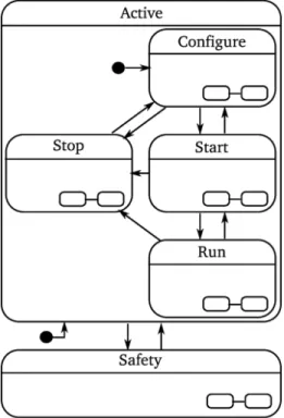
Fig. 4: Life-cycle coordination pattern. The Active state con-sists of a Configure, Start, Run, and Stop state. The Safety state next to the Active state allows transition to this Safety state at highest priority. Each state can be a state machine of its own indicated with the two connected ovals in the right corner of a state. Figure5gives an example of the sub-states. The arrows indicate a state transition which is triggered by an event, the filled black circle indicates an initial connector.
A Coordinator conforms to the life-cycle FSM of a Composite Functional Entity, as represented in figure4. Each of the states of the life-cycle FSM can be a state machine on its own, hence a Coordinator is a hierarchical FSM. The following states make part of the life-cycle FSM:
• The Active state which consists of the Configure, Start, Run and Stop state. This state is the initial state when a Coordinator is brought up, indicated by the initial connector in figure4.
• The Configure state coordinates the composition and con-figuration of the Composite Functional Entity. In the Con-figure state the Coordinator triggers the Composer and the Configurator. The Composer composes the entities of the Composite Functional Entity by creat-ing entities (deployment) and connectcreat-ing communication channels between entities, as explained in section3 and
7. The Configurator loads and executes the configu-ration of all entities of the Composite Functional Entity, following the Coordinator-Configurator pattern [31] as explained in section 5. The Coordinator triggers the Composer and the Configurator inter-mittent, since some steps of the composition need prior
configuration. For example the creation of communica-tion ports of the Scene dependent of the number of Tasks(configuration step), which can only be connected after their creation (composition step). This sub-state is the initial sub-state when a Coordinator is brought up, indicated by the initial connector in figure4. • The Start state coordinates the preparation of the entities
of the Composite Functional Entity for nominal opera-tion. In the Start state the Coordinator triggers the Schedulerto initialize, and Functional Entities to start computation and data exchange.
• The Run state is the state of nominal operation of the Composite Functional Entity. On the one hand, the Coordinator triggers when entering this state the activation of the Scheduler. On the other hand, it influences the run-time behavior of the Composite Functional Entity. This run-time behavior consists of altering the active set and configuration of Functional Entities, based on incoming events fired by for exam-ple the Monitor. For examexam-ple the configuration of the
Constraint-Based Program consists of amongst
others, the set of active tasks, the involved objects and (parts of) robots, and the task weights and priorities. • The Stop state coordinates the termination and destruction
of the entities of a Composite Functional Entity. In this state, the Coordinator triggers the Configurator to do the ‘opposite’ of the actions during the Configure state.
• The Safety state brings the composite state in a safe mode, which does not necessarily correspond with the Stop state. Since the Safety state is located on a higher level in the state machine hierarchy, events triggering a transition to the Safety state will have always priority, independent of the current sub-state within the Active state. For example blocking the motors of a robot in an application in which the robot has to handle dangerous materials, or on the contrary, bringing the robot to gravity compensation mode when working close to humans. As the initial connector indicates, recovering from a Safety state requires a reconfiguration.
The different Coordinators over the different composi-tion levels interact by events, forming a hierarchy of concur-rently executed (hierarchical) FSMsin which the higher level Coordinatorcoordinates the lower level Coordinators. Remark that not all Coordinators need to be in the same state, for example when a new Task is added to an existing Constraint-Based Programin the Run state and needs to go through the life-cycle until the Run state.
The life-cycle FSM takes part in the deployment of the system. A bootstrap brings up the highest level Composer that deploys the Coordinator and communication between them. Further this bootstrap ensures the configuration of the highest level Configurator. The Coordinator brings
up the remainder of the Composite Functional Entity by a coordination of a series of composition and configuration steps, using the Coordinator-Configurator [31] and Coordinator-Composer pattern, explained in section 3
and5.
The advantages of this approach of deployment are (i) the systematic approach to bring up a system, (ii) the reduction of the actual phase of bringing up the system to a ’minimal’ bootstrap, by using the structure of the composition, (iii) the predictability of the deployment procedure and its possible errors.
In addition to the Coordinator, the Scheduler forms part of the coordination. The Scheduler handles the or-der of the computations by the Functional Entities. However it forms not part of the Coordinator, since (i) a Scheduler uses service calls or events, therefore it is not a pure event processor, (ii) a Scheduler forms a periodic (time-triggered) process with respect to the (mostly) aperiodically, event triggered behavior of the Coordinator, (iii) a Scheduler depends on the implementation of the Functional Entities, (iv) a Scheduler must be fast and efficient, and can therefore be optimized using specialized routines. Scheduler and Coordinator are separately triggered by their counterpart at a higher level of composition, hence the Schedulers of each Compos-ite Functional Entity form also a hierarchy of concurrently executed (hierarchical) FSMs. This separation avoids cou-pling of the timing of Scheduler and Coordinator, that could cause delays in the scheduling. For example the
Scheduler iTaSC scheduler of a Constraint-Based
Program iTaSC triggers a Functional Entity Task
that itself is a Composite Functional Entity, this Task should immediately execute the algorithm, hence trigger its own Scheduler Task scheduler and not wait for its own Coordinator Task coordinator to command the Task scheduler to do so. This avoids the situations where 1) the Task coordinator has to react on both an event causing a behavior change and the trigger from the iTaSC scheduler, 2) and the situation where the Task coordinator only reacts on the trigger from the iTaSC scheduler in a next timestep (section 6.2).
6.1.1 Concrete model of the life-cycle FSM
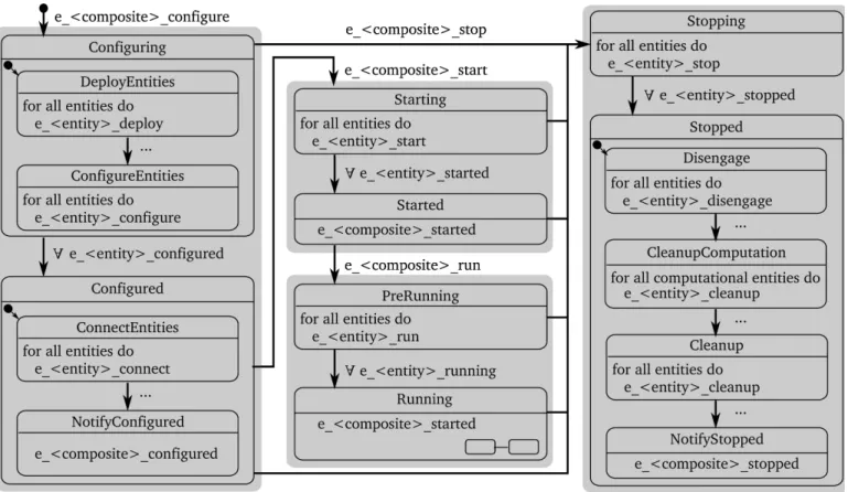
Figure5shows the details of the sub-states of the Active state of the life-cycle FSM. The grey boxes on figure 5 indicate these sub-states: Configure, Start, Run and Stop. They have each two sub-states: one with a name ending on -ing and one with a name ending on -ed, with exception of the Run state which has a PreRunning and a Running sub-state for linguistical reasons.
When in a -ing state, composite entities are coordinated, before triggering the Coordinators of its child entities. When in a -ed state, composite entities are coordinated after the Coordinators of the child entities are triggered but
Fig. 6: Example of the interaction between Coordinators at different levels of composition. The dashed arrows indicate how the raised event triggers a transition.
before the parent Coordinators are notified with an event. The Composite Functional Entity will be further on referred to as the composite.
A parent Coordinator triggers the transition to an -ing state, hence the name of the composite that the
Coordinator belongs to is in the event name. A
Coordinatortransitions from an -ing state to an -ed state when triggered by events from the child Coordinators. Due to this hierarchy the Active sub-states consist of exactly two states.
For example within the Configure state of a
Constraint-Based Program iTaSC that has two
composite child entities: the Tasks ApproachObject
and AvoidObstacle, as shown in figure 6. The
events e_ApproachObject_configured and
e_ApproachObject_configured raised by their
respectively Tasks trigger the transition from the Configuring state of the Constraint-Based Program iTaSC to its Configured state.
Another example is shown in figure3 and was detailed in previous sections.
Transitions that require events from multiple child Coordinatorsrequire the event memory extention of rFSM in order to avoid synchronization problems. An event is in the rFSM model an edge triggered event that lives only at that
Fig. 5: Detail of the Active state of the life-cycle FSM with example events. The arrows indicate a state transition which is triggered by an event, the filled black circle indicates an initial connector. Names starting with ’e ’ denote events. Events next to arrows indicate the events that a state is waiting for to make that transition, events within a state indicate the events sent out by the state. The ∀ symbol denotes that all events of that type need to be raised to make that transition. < entity > denotes a name of an entity within the composite, < composite > denotes the name of the Composite Functional Entity this Coordinatorbelongs to. The grey background denotes the sub-states of the Active state as shown in figure4. Events that trigger the lowest level transitions are replaced by . . . for readability. Also returning transitions such as from PreRunning to Started are left out for readability.
time instant. The event memory extension registers all events that could trigger a transition from the current state, starting from the moment the state was entered. In other words the event memory is cleared with every new state that is entered. The following paragraphs give an overview of the function of each sub-state:
• The Configuring state consists of two sub-states: De-ployEntities and ConfigureEntities. The first triggers the Composer to create the entities within the composite. The Composer will also enable event flow between the entities. The creation of child composite entities consists of the creation of its Coordinator, Configurator, and Composer, similar to the execution of the bootstrap to bring up the root Composite Functional Entity as mentioned in 6.1. A status event from the Composer triggers the transition to the second sub-state. The Con-figureEntities sub-state triggers the Configurators to configure the entities within the composite and the Coordinatorsof child composite entities to transition
to their Configuring state.
• The Configured state consists also of two sub-states: ConnectEntities and NotifyConfigured. The first con-nects the data flow between the entities of the com-posite. This connection is made after the configuration of the child composite entities, since connections can be configuration dependent. The NotifyConfigured sub-state notifies the completion of the configuration step to the Coordinator of the parent Composite Functional Entity.
• The Starting state triggers the Scheduler to initialize, Functional Entitiesto start computation and data exchange, and triggers the Coordinators of child composite entities to transition to their Starting state. • The Started state has as only function the notification to
the Coordinator of the parent Composite Functional Entity.
• The PreRunning state triggers the Coordinators of the child composite entities to transition to the
Pre-Running state. It further triggers the activation of the Scheduler.
• The Running state notifies the Coordinator of the parent Composite Functional Entity and coordinates the run time behavior as explained in section 6.1.
• The Stopping state has as only function the triggering of the Coordinators of child composite entities to go to the Stopping state.
• The Stopped state consists of four sub-states: Disengage, CleanupComputation, Cleanup, and NotifyStopped. The disengage sub-state triggers shutdown procedures, for example locking robot axes. The cleanup phase con-sists of two steps: CleanupComputation and Cleanup. The CleanupComputation state triggers the destruction of Functional Entities, including child composite entities. The Cleanup state triggers the destruction of the other entities within a composite. This distinction of two states allows the Coordinator to react on prob-lems when destroying the Functional Entities for which it needs the other entities within a composite. In the last sub-state, NotifyStopped, the completion of the stopping is notified to the Coordinator of the parent Composite Functional Entity.
The execution of this pattern of coordination requires a model that provides the information of all separate parts and their relations. The iTaSC DSL [29] is an example that provides such a model.
The interaction of Coordinators outlined in previous paragraphs, details interaction in case of the existence of a parent Composite Functional Entity to the composite under consideration. The Coordinator of the root Composite Functional Entity will transition from a -ed to -ing state after completion of the latter, not triggered by an event of a parent Coordinator.
The same structure applies to all entities, also for example to the Driver and its sub-entities that coordinates robot hardware co-operation when composing different hardware.
6.2 Implementation
The iTaSC software framework uses the Lua reference im-plementation of the rFSM DSL for the Coordinator, that conform to the models presented in previous sub-sections. These rFSM models are loaded in an Orocos-Lua component as for the Composer, Configurator and Scheduler, providing Communication and Configuration infrastructure to the entity. This component will be named Supervisor further on.
A Supervisor exposes the events raised within a
Coordinatorto an Orocos port, this port is connected to the other entities within a composite by the Composer. Through other Orocos ports, the Supervisor and hence Coordinator receives events.
The implementation considers two types of events, related to the state machine progression of the Coordinator:
1) common events, which are processed at each update of the Coordinator, 2) priority events, which are processed upon receiving them.
Most events are common events. Priority events are mainly used for 1) timer events, sent out by a periodic Timer to the root Composite Functional Entity, 2) events sent out by a Scheduler to trigger a Functional Entity, or its child Scheduler when that Functional Entity is a composite, 3) events that signal a fatal error, such as an
e_emergency event. Hence a Coordinator is a hybrid
event-triggered and time-triggered system.
The Timer triggers the Scheduler of the root Compos-ite Functional Entity, which triggers his leaf Schedulers, which on their turn trigger their leaf Schedulers etc.
The implementation provides a boiler plate script for the life-cycle FSM, which is a general model and allows ‘plugging in’ the application specific part of the Running sub-state machine. These application specific parts can be developed and saved as separate rFSM models and hence files.
As mentioned in the modelling Section, a Coordinator knows the other entities within a composite, this knowledge is provided by the configuration of the Coordinator, derived for example from the iTaSC DSL model.
The current implementation provides a basic Scheduler, that requests operations on Orocos components in an algorith-mic correct order with respect to the iTaSC concept.
6.3 Discussion and lessons learned
As detailed in previous sections, separating the
Configuratorand Composer from the Coordinator,
leaves the Coordinator with no software platform specific actions, and is hence reusable with any other framework.
Remark that in the proposed life-cycle FSM a state triggers the execution of ‘actions’ by other entities. These actions happen when being in a state, while transitions are light weight event based transitions. This forms a difference with the life cycle FSM of Orocos, where the actions, i.e. the execution of configuration etc., happen in between states. The advantages are that 1) the life-cycle FSM can react on errors when executing these actions, 2) a state of the life-cycle FSM can be divided in sub-FSM to coordinate this transition to the level of desired granularity.
7
C
OMMUNICATIONCommunication relates to the exchange of data [50], [4]. Dif-ferent communication mechanisms are possible, for example data flow, events, and service calls.
7.1 Modelling
The communication follows the commonly used connector design pattern [47], [51] that decouples dataflow between entities by abstracting the locality of the entities. It enforces a

![Fig. 2: Detail of the composition of computation (Functional Entities) for the explicit formulation of iTaSC using sysML flow ports [40]](https://thumb-eu.123doks.com/thumbv2/123dokorg/8065761.123741/9.918.77.844.119.411/composition-computation-functional-entities-explicit-formulation-itasc-using.webp)