2015
Publication Year
2020-03-18T18:02:26Z
Acceptance in OA@INAF
The ASTRI SST-2M prototype for the Cherenkov Telescope Array: opto-mechanical test results
Title
CANESTRARI, Rodolfo; GIRO, Enrico; ANTOLINI, ELISA; Bonnoli, Giacomo; CASCONE, Enrico; et al.
Authors 10.1117/12.2189767 DOI http://hdl.handle.net/20.500.12386/23378 Handle PROCEEDINGS OF SPIE Series 9603 Number
The ASTRI SST-2M prototype for the Cherenkov Telescope Array:
opto-mechanical test results
Rodolfo Canestrari
*a, Enrico Giro
b, Elisa Antolini
c, Giacomo Bonnoli
a, Enrico Cascone
d, Nicola La
Palombara
e, Giuseppe Leto
f, Giovanni Pareschi
a, Salvo Scuderi
f, Luca Stringhetti
e, Claudio Tanci
a,c,
Gino Tosti
cfor the ASTRI Collaboration
gand the CTA Consortium
ha
INAF-Osservatorio Astronomico di Brera – Via Bianchi, 46 23807 Merate (Lc) Italy
bINAF-Osservatorio Astronomico di Padova – Vicolo Osservatorio, 5 35122 Padova (Pd) Italy
c
Università di Perugia – Via A. Pascoli 06123 Perugia (Pg) Italy
d
INAF-Osservatorio Astronomico di Capodimonte – Salita Moiaiello, 16 80131 Napoli (Na) Italy
eINAF-Istituto di Astrofisica Spaziale e Fisica Cosmica di Milano – Via Bassini, 15 20133 Milano
f
INAF-Osservatorio Astrofisico di Catania – Via Santa Sofia 78 95123 Catania (Ct) Italy
ghttp://www.brera.inaf.it/astri/
h
http://www.cta-observatory.org/
ABSTRACT
The Cherenkov Telescope Array (CTA) observatory, with a combination of large-, medium-, and small-size telescopes (LST, MST and SST, respectively), will represent the next generation of imaging atmospheric Cherenkov telescopes. It will explore the very high-energy domain from a few tens of GeV up to few hundreds of TeV with unprecedented sensitivity, angular resolution and imaging resolution.
In this framework, the Italian ASTRI program, led by the Italian National Institute of Astrophysics (INAF), is currently developing a scientific and technological SST dual-mirror end-to-end prototype named ASTRI SST-2M. It is a4-meter class telescope; it adopts an aplanatic, wide-field, double-reflection optical layout in a Schwarzschild-Couder configuration. The ASTRI SST-2M telescope structure and mirrors have been already installed at the INAF observing station at Serra La Nave, on Mt. Etna (Sicily, Italy).
In this contribution we report about the on-site deployment and the latest results on the opto-mechanical performance test conducted soon after the telescope installation.
Keywords: imaging atmospheric Cherenkov telescope, very high-energy gamma-rays, wide-field aplanatic telescope,
CTA, ASTRI, segmented optics
1. INTRODUCTION
Recent advances in Gamma-ray astronomy have shown that the 10 GeV – 100 TeV energy band is crucial to investigate scientific topics such as pulsars and binary systems, blazars, radio-galaxies, the galactic center, pulsar wind nebulae and star-forming galaxies, as well as the physics in extreme conditions. A cost-effective way to perform observations in this band is with ground-based experiments through imaging atmospheric Cherenkov telescopes. Very-high energy photons (and cosmic rays) interact with the Earth atmosphere and generate an e+e- couple. The pair travels faster than light in the
medium and polarizes the molecules of the air. A faint flash of beamed photons in the 300-550 nm wavelength band is emitted at the de-excitation. This phenomenon is known as the Cherenkov effect, which is effective until the energy of
Optics for EUV, X-Ray, and Gamma-Ray Astronomy VII, edited by Stephen L. O'Dell, Giovanni Pareschi, Proc. of SPIE Vol. 9603, 960303 · © 2015 SPIE · CCC code: 0277-786X/15/$18 · doi: 10.1117/12.2189767
Proc. of SPIE Vol. 9603 960303-1
the gamma-rays goes below the threshold for pair production in air. Air Cherenkov telescopes collect the flash of photons using suitable multi-pixel sensors and make morphological analysis of the images.
At present, H.E.S.S. [1], VERITAS [2] and MAGIC [3] are the state of the art of such ground-based experiments. The Cherenkov Telescope Array (CTA) will represent a breakthrough in this field [4].
CTA has the goal of increasing the sensitivity by a factor of 10, to expand the detection bandwidth both in the low- and in the high-energy limits, and improve the angular resolution with respect to the present installations. The CTA observatory is a project involving a worldwide consortium of research Institutes and Universities that will make use of cutting-edge technologies. The observatory will be deployed over two sites, one for each hemisphere, in order to ensure full sky coverage observations. CTA will be composed of telescopes with different sizes. At the CTA southern site, 70 Small Size Telescopes (4 m primary mirror diameter), 25 Medium Size Telescopes (12 m) and 4 Large Size Telescopes (23 m) are envisaged. Additional 24 Schwarzschild-Couder Telescopes (9 m) will be possibly installed to improve the sensitivity at about 1 TeV and to exploit high-precision angular resolution studies. In the northern site, 15 Medium Size Telescopes (12 m) and 4 Large Size Telescopes (23 m) are planned. The Medium Size and the Schwarzschild-Couder telescopes are discussed in [5] and [6].
The Italian National Institute for Astrophysics (INAF) is leading the design and development of an end-to-end telescope prototype for the SST class. This activity is carried out within the ASTRI flagship project funded by the Italian Ministry of Education, University and Research. The follow-up of the ASTRI project consists of the deployment of the first pre-production telescopes on the CTA southern site. This follow up is partially funded also by the Fundação de Amparo à Pesquisa do Estado de São Paulo and by the Department of Science and Technology of the Republic of South Africa. The mini-array will be the seed from which the entire CTA southern site will be deployed.
INAF has committed the electro-mechanical design of the telescope prototype, named ASTRI SST-2M, to BCV progetti (www.bcv.it) and Tomelleri (www.tomelleri.com) companies, while INAF has kept in house the design and the development of optics, mirrors, detector and software. Details on the design are reported in [7], [8] and [9]. The manufacturing of the electro-mechanical structure of the telescope has been awarded to Galbiati group (www.galbiatigroup.it) and EIE group (www.eie.it) companies forming the GEC consortium. Details on the manufacturing are in [10] and [11].
The site of the ASTRI SST-2M opto-mechanical structure is the “M. G. Fracastoro” observing station in Serra La Nave (Sicily, Italy), at about 1735 m a.s.l. [12]. It is in operation since September 2014.
In the following sections we give a short overview of the opto-mechanical solutions implemented (see section 2) and then we report the results from the initial on-site tests (see section 3).
2. THE TELESCOPE DESIGN
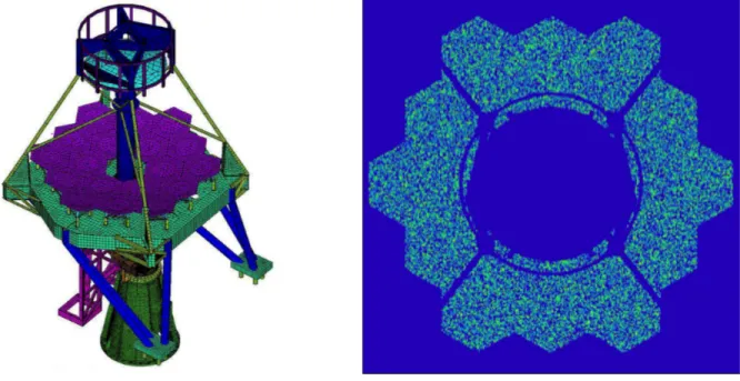
The mechanical design of the ASTRI SST–2M telescope prototype is the outcome of trade-off activities among different configurations. The chosen solution has been further refined and optimized until the results of the analyses met the design specifications. Finite Elements numerical approach (FE Model and FE Analysis) is the design verification tool adopted for the static evaluation of all the telescope structural components. The integrated FE model of the telescope has about 700.000 degrees of freedom. It takes into account also the characteristic of the mechanical components, the mirrors and other devices on board of the telescope (shields, baffle, scientific detector, etc.). An example of the FE model developed within the design phase of the project is shown in the left panel of
Figure 1
. Simple dynamical analyses have also been performed in order to investigate the non-static behavior of the telescope.The dimensioning of the structural components was driven by the CTA project requirements such as the design loads, the optical tolerances, reliability-availability-maintainability-safety criteria and others. Indeed, the structural checks (e.g. winds, earthquakes, etc.) have been performed in accordance with the most updated national and international norms and standards (i.e. Eurocodes, EC machinery directive). The evaluation of the telescope in terms of optical-related performance (vignetting, mis-alignments/mis-orientations of the mirrors) has been computed by means of ray-tracing analysis.
The Eigen-frequencies have a nearly constant behavior with respect to the azimuth axis; the first modes have values in any case higher than 4 Hz. They are a twist around the azimuth axis and tilts around elevation and cross-elevation axes ascribed to the stiffness of the mechanical components. Dynamic behavior on tracking shows stick and slip phenomenon due to the difference between static and dynamic friction on the azimuth bearing. However, the global tracking errors of the order of few arcsec rms also in presence of wind disturbances are well below the specification.
Proc. of SPIE Vol. 9603 960303-2
Concerning optical degradations due to structural performance, we observe that the point spread function remains within the requirement in any observing condition while the obstruction is at most of about 14%. The right panel of
Figure 1
shows the ray-tracing of the ZEMAX configuration implemented for this purpose.
Figure 1: (left) Global finite element model of the ASTRI SST-2M telescope prototype. (right) Evaluation of the obstruction due to
the optical elements and the mechanical structures of the telescope. 2.1 The electro-mechanical configuration
The ASTRI SST-2M telescope structure is primarily made of steel grade S355 material. It has an alt-azimuthal mounting type. The base is a truncated cone with reinforcing ribs to distribute loads. The base interfaces the concrete foundation by means of 24 anchor bolts, earthquake devices and electrical/communication terminals. At the opposite end, the azimuth bearing and main gear are hosted. Inside the base, the azimuth strip encoder with 4 scanning heads, the references for the motion’s limit switches and the cables routing are disposed. A door is available to give access to these devices.
The azimuth fork, one of the main structural elements, is mounted on top of the telescope base together with the azimuth drive system (motors and gear boxes). The drive system has two units that work in master-slave configuration during both slewing and tracking. This operative mode neglects the backlash and guarantees adequate precision during the motion. The fork interfaces the primary mirror cell and the elevation actuator. The support frame for the electrical cabinets, the cable trays and the elevation cable wraps are also hosted on the fork. The fork can rotate around the azimuth axis for 540°.
The cell of the primary mirror is a thick ribbed flat dish of about 4.3 meter in side. It is moved around the elevation axis by a long and stiff linear actuator within the range −5° and +95°. The actuator, manufactured from Servomech company [13], has a single motor with preloaded gearbox. Backlash is completely removed because the telescope is slightly unbalanced about the elevation axis. A rotary absolute encoder is directly coupled to the elevation axis. The dish hosts 18 reflective segments, that compose the primary mirror; the quadrupode, that supports the secondary mirror; and the central tube, that supports the focal plane instrument. The quadrupode has an eccentric symmetry with radial bracings toward the central tube; this solution improves the bending stiffness against gravity deformations introduced by the large secondary mirror.
A triangular prism and a proper arrangement of tapered I-beams compose the cell of the secondary mirror. The triangular prism supports the mirror subsystem itself while the tapered beams provide interfaces toward the quadrupode legs. The cell also has supports the snow shields, windshields and optical baffles.
Proc. of SPIE Vol. 9603 960303-3
Electromecha the telescope Concerning t both azimuth the motor SE available on drill for emer The motion company [14 The telescop accordingly t IP65. The el between 0°C integrated ins The high pow installed. Thi disconnection The high pow The low pow charge to con the servo m data/commun to open the c the other cabi The rendering
anical stow pi in position up the drive syste h and elevation EW CM90S i both axes; mo rgency situatio control, safet ]. The fieldbu pe has two el o IEC 61439 lectrical cabin to 40°C for side the cabine wer cabinet p
is device gua n function, wh wer cabinet als wer cabinet is ntrol and moni minor drives nication. At th circuit also wh inet. g of the ASTR Figure 2 Re
ins are design p to the worst em of the tel n. In azimuth, s used. A bra oreover a sec ons (power cu ty and health us is based on lectrical cabin and EN 60204 nets are therm any environm ets; moreover provides the m arantees the p hich ensures t so hosts drives a complex su itor the telesc
(primary an he entrance of
hen energized RI SST–2M te
endering of the
ned for lockin loading condi escope a solu , the ratio-gea ake (braking t ondary motor uts, drive or so monitoring s EtherCAT sta nets: the high 4-1. Both cab mally controll mental conditio , an anti-cond main power di protection of that the electr s and inverter ubsystem that
ope; the hardw nd secondary f the cabinet a d while the ov elescope proto ASTRI SST-2M ng the telescop itions. Elevati ution based on ar is SEW R97 torque equal r shaft allows oftware failure systems are b andard. h power cabi binets are desig
led. They gua ons. Heating densation resis istribution to the downstre rical circuit is electronics of t hosts a numb ware in charg y mirrors ali a load disconn ver-current pro otype is shown M telescope str pe in parking ion bumpers a n SEW-Eurod 7R57 with the to 5 Nm) wit the driving o es etc.). based on PC/ inet and the gned for outdo arantee norma resistors and stor is present
the entire tel eam circuits s completely d f the motion s ber of device e to power so gnment syste necting switch otection is pro n in
Figure 2
ructure and elec
position. The are also envisa drives compon e motor SEW th automatic of the telescop /PLC solution low power c oor applicatio al operation fans have be opportunely c lescope. At it against over-de-energized f system.
s such as: all ome specific an
em); the har h is installed. I ovided by the
2
. ctro-mechanical ey are designe aged.nents has bee CM71S; whil and manual r pe with the ai n by Beckhof cabinet. They ons with a pro
of the install en opportunel commanded b s entrance a -currents toge for service or the electroni nd auxiliary e rdware in ch It guarantees t circuit break l subsystems ed for locking en adopted for le in elevation release is also id of a battery ff Automation are designed tection degree led equipment ly chosen and by a hygrostat. switch fuse is ether with the r maintenance c hardware in equipment and harge of the the possibility ker installed in g r n o y n d e t d . s e . n d e y n
Proc. of SPIE Vol. 9603 960303-4
0.20 -!_________l 0.1 8 -: -0.16 -:._________:: 0.14 -::_________.`: 0.12 -: o 0.10 -:_________-co D 0.08 -: 0.06 -:._________:: 0.04 -::_________.`: 0.02 -: 0.00 -I---f 0.0 0. I I I .5 1.0 1.5 2?.0 2.5 3.0 Field Angle [°] - - Pixel siz I Ì I 3.5 4.0 4.5 2.2 The opti The ASTRI Schwarzschil [15]. The actu CTA Observa than 4.5 m2 (e plate scale is
Figure 3
. The primary of about 4.3 surfaces have reaches devia respectively. shown in the Each mirror rough positio motors to per the mirror ar encoders prov through CAN The mirrors a processes tha identical mirr Concerning th the mirrors of over a replica together form deposited on presented in this conferen manufacturin telescope prim The secondar bending is gr of the second Figure 3 ical configura SST–2M pro ld-Couder conual layout imp atory. In parti enough to trig about 37.5 m mirror is tasse m. On the con e a concave p ations in terms The focal sur right panel of segment is m on. The suppo rform the fine rea on a whiff vide tip-tilt an Nbus. are manufactu at take advan rors. he primary m f the MAGIC– ation mold. To ming a stiff an the substrate [18] while an ce proceeding ng the entire s mary mirror ar ry mirror com ravity assisted dary mirror are
3: (left) Evolutio
ation
ototype imple nfiguration. V
plemented in icular, the pix gger at 1 − 3 T mm/°. The tren eled in 18 pan ntrary, the sec profile with v
s of peak-to-v face has a sph f
Figure 3
. mounted on aorts are equip e alignment of fletree configu nd piston mot ured adopting ntage by the c mirror, the tech –II telescope, o keep the sha d lightweight e. A detailed n overview of g [19]. This te set of mirrors re reported in mes from a mo d with a propr e reported in [ on of the angul im ements an ap Vassiliev et al the ASTRI SS xel size is 0.1 TeV). The tele nd of the angu nels distribute condary mirro very pronounc valley of PVM herical convex triangular spa pped with two f the mirror. C uration act as tion to the su in both cases concept of rep hnology adopt see [16] and ape, a reinforc sandwich stru description o f the projects t echnology, wi s for CTA. T [20]. onolithic glass rietary proces [21]. ar resolution al mplemented for planatic, wid . firstly propo ST–2M telesc 165°, the large escope has an ular resolution ed on three co or is a large m ced deviations 1 = 27 mm an x profile with acer that also o active actua Concerning the
s support. Thr ubsystem. All s a somewhat plica: the pro ted is the glas
[17]. A glass cing core in alu
ucture. At the of the princip that so far ha ith different im The measurem s plate 19 mm s developed b
long the field of r the ASTRI SS
de field, doub osed the use o cope follows t e field of view equivalent foc n along the fi oronae; they co monolithic ele s from the ge nd PVM2 = 1.3 a radius of cu introduces a ators and one e secondary m ree active actu the active op t similar techn ofile of a ma s cold shaping sheet is bent, uminum hone e end of the po ples over whic ave adopted th mplementatio ment results an m thick that un by the FLABE f view. (right) G ST-2M telescop ble reflection of this solutio the requiremen w is 9.6° and cal length of 2 eld of view is ompose the fu ement of 1.8 m enerating sphe 3 mm, for prim urvature of abo tilt to bring t fixed point. T mirror, a total uators with st ptics devices h nology. Both ster shape is g process rece at room temp eycomb and a olymerization ch the cold-s his technologi ns, is now be nd expected o ndergoes a the EG company Geometrical lay pe. n optical layo on to Cherenk nts for the SS the effective 2150 mm with s shown in the ull aperture of m in diameter ere. In fact, th mary and seco
out 1060 mm. the mirror seg The actuators of 9 points di tepper motors have drives co are made in g copied to pr ently develop perature, by va second glass n a high reflect haping proce ical solution i eing adopted a optical perfor ermal bending (www.flabeg
yout of the optic
out known as kov telescopes ST array of the area is larger h F# = 0.5; the e left panel of f the telescope r. Both optica he asphericity ondary mirrors . The layout is gment into its s have stepper istributed over s and absolute ommunicating glass applying roduce severa ed for making acuum suction skin are glued tive coating is ss is based is s presented in as baseline for rmance of the g process. The .com). Details cal design s s e r e f e l y s s s r r e g g l g n d s s n r e e s
Proc. of SPIE Vol. 9603 960303-5
*<...'t
41-3. THE ON-SITE INSTALLATION AND PRELIMINARY TESTS RESULTS
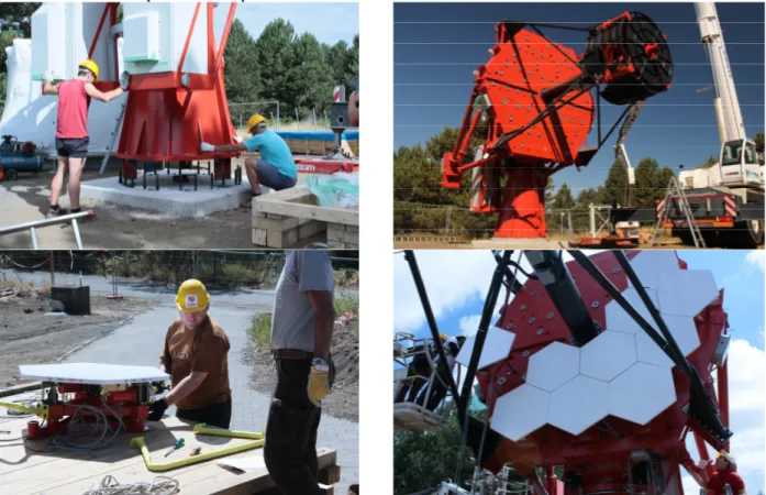
3.1 The telescope installation
Figure 4
shows the main phases of the ASTRI SST-2M prototype on-site installation.The assembly of the telescope has begun on August 22nd 2014 with the positioning of the mount assembly on the
foundations (see
Figure 4
top-left panel): the base, the fork and the electrical cabinets were pre-assembled at the factory, packed and shipped. Grouting has been concurrently executed. The perpendicularity has been measured by means of a spirit level with 2 arcsec resolution. The alignment tilt error is below 20 arcsec with respect to the gravity vector. The tensioning of the anchor bolts has been performed in two separate steps by means of a hydraulic jack up to the design value of 230 kN. The remaining structural parts of the telescope (the primary mirror dish, the quadrupode, the secondary mirror cell and the counterweights) have been installed, as per assembly plan, in the subsequent 5 days (seeFigure 4
top-right panel).The second phase was devoted to mirrors installation. Each segment of the primary mirror has been integrated to its active support structure and, using proper handling tools (see Figure 4 bottom-left panel), installed on the telescope (see Figure 4 bottom-right panel) as per procedure. Two days were necessary to complete the installation of the 18 segments of the primary mirror.
Three high-skilled mechanical technicians, one crane operator and an engineer coordinating the activities have carried out the opto-mechanical installation in about 10 days. The main supporting equipment was a mobile crane for lifting and positioning of the structural elements and a cherry picker to bring the technicians in place.
At last, the electrical routing and cabling of the entire telescope and auxiliary subsystems have been done. Two technicians and an engineer coordinating the activities have completed the work in 10 additional days.
At the end, the first complete integration on field of the ASTRI SST-2M prototype took more or less 30 days, including the materials on-site acceptance and inspection.
Figure 4: Highlights of the telescope opto-mechanical on-site installation. (top-left) Positioning and alignment of the mount assembly
on the foundation (top-right) Completion of the telescope structure (bottom-left) Primary mirror segments and active optical support integration (bottom-right) Primary mirror installation.
Proc. of SPIE Vol. 9603 960303-6
O
> É
ASTRI SST -2M azimuth movement - open loop
400 É 200 - Actual velocity Commanded position - Position error o 0.0 °n E 2.0 u 20 40 60 80 100 120 140 160 180 Time [s]
r
0.0 8 -0.5 7,-1.0 ó é -1.5i
-2.0 ,L -2.5 100 80 60 4 40 20 0 °_ 4 0ASTRI SST -2M elevation movement - open loop
4-Actual velocity - Actual position Commanded postion - Position error i i i i i i i i i i i 0 5 10 15 20 25 30 35 40 45 50 55 60 Time [s]
3.2 Electro-mechanical and opto-mechanical tests
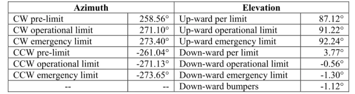
The electro-mechanical tests consist in a series of functional tests to assess the low level performance of the telescope. Tests concern for instance the electrical functionality of all the limit switches as well as their intervention on the telescope motion (interlock chain), the maximum velocities and accelerations achievable, the braking range upon emergency stop, the motors torque bias, the stow pins insertion and extraction, the axes motion range amplitude, the emergency movement, the telescope Eigen frequencies, the power consumption and the duration of the telescope control and safety subsystems under UPS.
To evaluate the axes motion a dedicated test has been performed. The telescope has been commanded to perform a full run at its maximum velocity until the limit switches intervention. The telescope shows a wide operation range both on azimuth and elevation. The total usable run during observation is 542.23° in azimuth and 91.78° in elevation. The chain of switches to limit the motion range is formed by a pre-limit to slow down the velocity, an operational limit and an emergency limit. Each axis has two chains, one for each direction of the motion. A summary of the positions of intervention of the limit switches is reported in Table 1.
During this test it has been possible to verify also the maximum velocities of the axes and the open-loop positioning error during the run. Figure 5 shows the axis performance moving at maximum velocity achieved (red slim line), the full motion range (actual in red and commanded in black) and the positioning error during the run (orange line) for both axes. The telescope is able to reach 4.5°/s in azimuth in such a way to complete a full turn in less than 80 s. Elevation reaches 2°/s and hence completes its run in less than 45 sec. The motion shows also a good positioning precision despite the open-loop configuration. In fact, the azimuth error is limited to about 2 arcmin while the elevation error remains below ±3.5 arcmin.
Table 1: Limit switches intervention position for the clock-wise (CW) and counter clock-wise (CCW) azimuth directions and for
zenith (up-ward) and horizon (down-ward) elevation directions.
Azimuth Elevation
CW pre-limit 258.56° Up-ward per limit 87.12° CW operational limit 271.10° Up-ward operational limit 91.22° CW emergency limit 273.40° Up-ward emergency limit 92.24° CCW pre-limit -261.04° Down-ward per limit 3.77° CCW operational limit -271.13° Down-ward operational limit -0.56° CCW emergency limit -273.65° Down-ward emergency limit -1.30°
-- -- Down-ward bumpers -1.12°
Figure 5: Full range movement for azimuth (left) and elevation (right) axes. The plots show the maximum velocities achieved (red
slim line on top), the motion range (red and black lines) and the positioning errors during the run (orange line).
Proc. of SPIE Vol. 9603 960303-7
ASTRI SST -2M azimuth emergency stop responce
É
á 180.0 -_
- Emergency stop -button release
179.5 = 179.0- 178.5-178.0-E E 177.5 Q -177.0 =
Max angular stroke: 2.5° in 0.85s
-176.5- ï I I i I 30 31 32 33 34 Time [s] 35 36 37 2.0 1.5 > 1.0 0.5 0.0 > w 21.20- 21.15-,. 21.10-ó 21.05-ó 21.00-a c 20.95-Á 20.90-> 20.8520.80 -20.75 14.5
ASTRI SST -2M elevation emergency stop responce
- Emergency stop- button release Max angular stroke: 0.38" in 0.39s
15.0 15.5 Time [s] 16.0 16.5 1400 1200 3 1000 800 $ 600 3
i
400 200ASTRI SST -2M power consumption during slewing - Phase 1 - Phase 2 - Phase 3 10 15 20 25 30 35 40 45 50 Time [s] 440 400 360 3 320 280 240 ó 200 160
i
120 80 40 gASTRI SST -2M power consumption during tracking - Phase 1 - Phase 2 - Phase 3 1-144 0 50 100 150 200 250 300 350 400 450 500 550 600 Time [s]
The emergency movement is done by means of an electrical drill connected to a second shaft of both axes motors. A test was performed in order to evaluate the maximum velocities achievable and hence the maximum time needed to park the telescope in case of an emergency situation that implies a failure of the motion control system. During the test, the motion of each axis has been verified on both directions. The results show a maximum velocity of 1.5°/s for the azimuth axis and 0.4°/s for the elevation. Less than 4 minutes are needed to drive the telescope to its parking position with the emergency toolkit.
The emergency braking range has been evaluated after the push of the red safety button during a fast slewing movement. The test has been repeated for both axes. The test results are shown in Figure 6. In azimuth the telescope brakes in 2.3° within 0.61° then few oscillations are triggered. These oscillations have a maximum amplitude of 0.2° and are completely dumped within 4 s. Similarly, in elevation the telescope brakes in 0.37° within 0.34° then few oscillations are also triggered. These oscillations have a maximum amplitude of 0.01° and are completely dumped in less than 1.5 s. An estimation of the power consumption of the telescope has been also verified both during a fast slewing and during tracking. Figure 7 shows the cumulative consumption (of each phase of the power supply of the telescope) for the motors and drives system, the motion control and the safety units. The telescope requests a peak of power of about 3.8 kW during the fast slewing while it keeps its consumption to about 0.5 kW during the tracking phase.
Figure 6: Behavior of the telescope upon an emergency stop. After the emergency-stop button intervention the telescope motion gets
a complete stop within1 s for both axis. Oscillations are triggered and quickly dumped. (left) Azimuth axis. (right) Elevation axis.
Figure 7: Power consumption of the ASTRI SST-2M telescope during a fast slewing (left) and tracking (right) operation.
Proc. of SPIE Vol. 9603 960303-8
ASTRI SST -2M azimuth tracking - close loop 0.2 0.1 -0.0 -41.--0.1
0.2 269.5 -c 269.0 -o -(7) -o 268.5-+, E á 268.0 267.5 -- Actual trajectory - - - Commanded trajectory- Tracking error: - average = 3 arcsec - rms = 5.5 arcsec
14 00
0 100 200 300 400 500 600
Time [s]
ASTRI SST -2M elevation tracking - close loop 0.4 -0.2 0.0 0.2 -0.4 37.0 -C
°
36.5-,
o aó
J36.0 -> a w 35.535.0 -0 WA - Actual trajectory - - - Commanded trajectory- Tracking error: - average = -3.5 aresec - rms = 11.5 aresec
100 200 300 400 500 600
Time [s]
The opto-mechanical performance has been evaluated in terms of positioning and tracking errors. Concerning the tracking errors, the trajectory’s coordinates generated by the telescope motion controller and the actual position of the telescope retrieved by the encoders reading during the run have been acquired. The tracking error has been evaluated as the rms differences of the two trajectories. The test has been repeated for a number of trajectories at different azimuth and elevation positions. A typical behavior is shown in Figure 8; the tracking error is of the order of 5.5 arcsec in azimuth and 11.5 arcsec in elevation over 10 minutes run.
Figure 8: Tracking error test. The telescope has been commanded to follow a number of trajectories. The commanded and actual
paths (encoders reading) have been recorded (red and black dashed lines). The difference between the two (green line) is the tracking error: (left) azimuth tracking error and (right) elevation tracking error.
Proc. of SPIE Vol. 9603 960303-9
850 mrr ioo 95 90 85 80 75 70
Primary mirror reflectivity: AI +Si02(130nm)
Weighted average; each mirror segment - Total average; 81300-sso7 = 87.1%
Theoretical profile 200 300 400 500 600 Wavelenght [nm] 700 800 100 95 90 T ? 85 d d 80 75 70
Seconday mirror reflectivity: AI +Si02(150nm)
Weighted average "A" Weighted average "B" Weighted average "C" Weighted average "D"
- Total average; R(soo-su, = 85.1% - - Theorical profile
200 300 400 500 600 Wavelenght [nm]
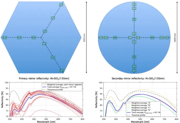
700 800 Optical tests so far performed at the telescope have concerned the monitoring of the eventual reflectivity degradation underwent by the primary and secondary mirrors coatings.
Local specular reflectivity has been measured with a spectrophotometer from Filmetrics, model F20-UVX equipped with an additional lamp model LS-DT2 Tungsten-Halogen and a CP-1 contact probe. Reflectance measurements have been taken in the spectral range 200-1700 nm and after 6 months of environmental ageing (winter season). Each segment of the primary mirror has been sampled over 9 points distributed on its surface. Instead, the secondary mirror was measured over 36 points. The measurement positions for both mirrors are shown in the top row of Figure 9. The bottom row shows the typical specular reflectivity curves measured at the telescope. Some differences with respect to the nominal profiles (black dashed lines are the simulated reflectivity curves) are detected. These can be ascribed both to deficiencies of deposition process and ageing due to environmental conditions. In any case, both coatings respect the reflectivity requirement imposed by the project.
Figure 9: Results of the reflectivity monitoring after 6 months of on-site ageing. (top-left) Measuring points on the primary mirror
segments. (top-right) Measuring points on the secondary mirror. (bottom-left) Typical reflectivity curves for the primary mirror. (bottom-right) Typical reflectivity curves for the secondary mirror.
4. CONCLUSIONS
This paper presents the on-site assembling and preliminary tests results of the ASTRI SST-2M telescope, prototype of the Small Size class of Telescopes with a Dual-mirror configuration for the Cherenkov Telescope Array.
The structural and mechanical designs of the telescope have been committed to experienced companies in the field of astronomical instrumentation. Same for the manufacturing of the electro-mechanical structure; it has been subcontracted to a consortium of top-level Italian companies.
Proc. of SPIE Vol. 9603 960303-10
All the structural and mechanical components of the telescope have been manufactured and preassembled on factory during the timeframe of February-August 2014. Shipping to the installation site was done in few days in August of the same year. The full assembly, including also the electrical cabling and the mirror installation, has been carried out in about three weeks of work between August and September 2014. The telescope structure has been officially inaugurated on September the 24th.
Movement (including axes close-loop tuning), safety and operation procedures have been developed and debugged during the following months as well as a number of electrical issues have been addressed.
Some tests involving the main functionalities of the telescope have been started. Preliminary results are reported in this proceeding. Even if some important tests have not yet been performed (such as the Eigen frequencies evaluation) the commissioning activities completed up to now yield a very positive behavior of the telescope. All the functionalities tested such as maximum axes range, maximum velocity, emergency braking range and emergency velocity movement are well within the requirements. Power consumption is inside the allocated budget and tracking accuracy seems well below the requirement with a good match with respect to the dynamic simulations.
Further tests and commissioning activities are ongoing and will last a few months.
ACKNOWLEDGMENTS
This work was partially supported by the ASTRI “Flagship Project" financed by the Italian Ministry of Education, University, and Research (MIUR) and led by the Italian National Institute of Astrophysics (INAF). We acknowledge partial support by the MIUR Bando PRIN 2009 and TeChe.it 2014 Special Grants. We also acknowledge support from the Brazilian Funding Agency FAPESP (Grant 2013/10559-5) and from the South African Department of Science and Technology through Funding Agreement 0227/2014 for the South African Gamma-Ray Astronomy Programme.
We gratefully acknowledge support from the agencies and organizations listed under Funding Agencies at this website:
http://www.cta-observatory.org/.
We also acknowledge the valuable collaboration of the consortium GEC composed by the companies EIE Group and Galbiati Group.
REFERENCES
[1] Hoffmann, W., et al., “The high energy stereoscopic system (HESS) project”, Contribution to AIP 515, 1999 [2] Holder, J., et al., “Status of the VERITAS Observatory”, Contribution to AIP 1085, 2008
[3] Ferenc, D., et al., “The MAGIC gamma-ray observatory”, NIM-A, 553, 274-281, 2005 [4] Acharya, B. S., et al., “Introducing the CTA concept”, Astroparticle Physics, 43, 3-18, 2013
[5] Oakes L., et al., “Results and developments from the 12m Davies-Cotton MST prototype for CTA”, this conference 9603-5 (2015)
[6] Rousselle J., et al., “Towards the construction of a medium size prototype Schwarzschild-Couder telescope for CTA”, this conference 9603-4 (2015)
[7] Canestrari R., et al., “The ASTRI SST-2M prototype for the next generation of Cherenkov telescopes: structure and mirrors,” Proceeding SPIE 8861, 886102 (2013)
[8] Catalano O., et al., “The camera of the ASTRI SST-2M prototype for the Cherenkov Telescope Array”, Proceeding SPIE 9147, 91470D (2014)
[9] Tosti, G., et al., “The ASTRI/CTA mini-array software system”, Proceeding SPIE 9152, 915204 (2014)
[10] Marchiori G., et al., “The ASTRI SST-2M prototype for the next generation of Cherenkov Telescope Array: prototype technologies, goals, and strategies for the future SST,” Proceeding SPIE 9145, 91450L (2014) [11] Canestrari R., et al., “The ASTRI SST-2M prototype for the Cherenkov Telescope Array: manufacturing of the
structure and the mirrors”, Proceeding SPIE 9145, 91450M (2014)
[12] Maccarone, M.C., et al., “The Site of the ASTRI SST-2M Telescope Prototype”, Proceeding 33rd ICRC , 0110
(2013)
[13] www.servomech.it
Proc. of SPIE Vol. 9603 960303-11
[14] www.beckhoff.com
[15] Vassiliev V., Fegan S. and Brousseau P., “Wide field aplanatic two-mirror telescopes for ground-based γ-ray astronomy”, Astroparticle Physics, 28, pages 10-27 (2007).
[16] Vernani D., et al., “Development of cold-slumping glass mirrors for imaging Cherenkov telescopes”, Proceeding SPIE 7018, 70180W (2008)
[17] Pareschi G., et al., “Glass mirrors by cold slumping to cover 100 m2 of the MAGIC II Cherenkov telescope
reflecting surface”, Proceeding SPIE 7018, 70180V (2008)
[18] Canestrari R., et al., “Cold-shaping of thin glass foils as novel method for mirrors processing. From the basic concepts to mass production of mirrors,” Optical Engineering, 52-5, 051204-1 (2013)
[19] Canestrari R., et al., “An overview on mirrors for Cherenkov telescopes manufactured by glass cold-shaping technology”, this conference 9603-1 (2015)
[20] Sironi G., et al., “ASTRI SST-2M Cherenkov Telescope Array prototype: M1 characterization”, this conference 9603-3 (2015)
[21] Rodeghiero G., et al., “Qualification and testing of a large hot slumped secondary mirror for Schwarszchild-Couder Imaging Air Cherenkov Telescopes”, submitted to PASP, 2015
Proc. of SPIE Vol. 9603 960303-12