Politecnico di Milano Scuola di Ingegneria dell’Informazione
Polo territoriale di Como Master of Science in Computer Engineering
An Indoor Localization system for gated
model village
Supervisor: Prof. Fabio Salice
Assistant Supervisor: M.Sc. Andrea Masciadri
Master Graduation Thesis by: Fabrizio Danese Student Id. number: 858449
. . . It means no worries For the rest of your days It’s our problem-free philosophy Hakuna Matata! . . .
Sommario
La popolazione mondiale sta invecchiando rapidamente e, con l’avanzare dell’et`a, la probabilit`a di soffrire di un lieve deterioramento cognitivo aumenta esponenzialmente. L’innovativo centro di assistenza sanitaria “Il Paese Ritrovato”, il primo gated model village per persone affette dal morbo di Alzheimer, `e un evento rivoluzionario nello scenario di cura a lungo termine dei disturbi cognitivi; il progetto mira a creare un am-biente libero in cui gli abitanti possano vivere in tranquillit`a e costantemente stimolati da terapie mediche e dalle interazioni sociali. Al fine di preservare l’indipendenza degli abitanti, il numero di Assistenti `e stato ridotto e ogni terapia `e resa non invadente e perfettamente integrata con la normale attivit`a quotidiana del villaggio.
Considerando la dimensione della struttura, la libert`a non convenzionale dei pazienti e la quantit`a limitata di risorse umane a disposizione, le attivit`a degli assis-tenti devono essere semplificate attraverso l’uso di un sistema tecnologico sviluppato appositamente per la supervisione della struttura.
Questa tesi illustra un sistema di localizzazione specificamente progettato per essere applicato in “Il Paese Ritrovato”, inaugurato il 28 febbraio 2018 a Monza, in Italia. Gli abitanti sono dotati di un braccialetto in plastica, stampato in 3D, contenente un beacon in grado di inviare continuamente pacchetti di dati con protocollo iBeacon, che vengono raccolti tramite l’uso di dispositivi Bluetooth Low Energy collegati in una rete locale. Il sistema valuta la perdita del segnale ricevuto e corregge la posizione stimata con un’analisi della scena che tiene conto dei possibili percorsi all’interno della struttura al fine di evitare errori per cui il segnale sembra aver attraversato la parete.
Le informazioni sulla localizzazione possono essere visualizzate su un’applicazione mobile appositamente progettata per supportare gli operatori sanitari durante il loro turno lavorativo.
Abstract
The world population is rapidly aging and, with the elder age, the probability of suffering from mild cognitive impairment increases exponentially. The highly innovative health-care facility “Il Paese Ritrovato”, the first Italian gated model village for people affected by Alzheimer’s disease, is a breakthrough event in the longterm care scenario of cognitive impairments; it aims to create an open environment in which the inhabitants could freely live and getting constantly stimulated by medical therapies and social interactions. In order to preserve the independence of the inhabitants, the number of caregivers has been reduced and every therapy needs to be non intrusive and perfectly blended with the regular daily activity of the village.
Considering the dimension of the structure, the unconventional freedom of the patients and the limited amount of human resources, the activities of the caregivers have to be simplified through the use of a system developed specifically for the supervision of the structure.
This thesis illustrates a localization system specifically designed to be applied in “Il Paese Ritrovato”, inaugurated on February 28th in Monza, Italy. The inhabitants are provided with a 3D-printable bracelet containing an iBeacon broadcasting data packets that are collected through the use of a Bluetooth Low Energy devices connected in a local network. The system evaluates the path-loss of the received signal and corrects the estimated position with a scene analysis that takes into account the possible pathway inside the facility in order to avoid the wall-crossing phenomena.
Localization information can be displayed on a mobile application that is specifically designed for support the caregivers during their working shift.
Acknowledgments
I would like to express my gratitude to Professor Fabio Salice for entrusting me with such a delicate job: Helping others. It was a great honor to collaborate with the Assistive Technology Group in order to create a system that is able to help someone like the caregivers in Monza and their assisted with Alzheimer’s.
Thanks to Andrea Masciadri, for putting the S to a sincere friendship that I hope will lay the foundations for an endless and fruitful collaboration.
Thanks to Emanuele De Bernardi, Stefano Gorla, Federico Bianchi and Fabio Veronese for the inspiration, the tea break, the listening, the help with the English, the support and the infinite patience that you all have demonstrated to me during this months of forced cohabitation in your office. Thanks for creating such a strong connection and great atmosphere in the team.
Thanks to my friends of the Mani team: Andrea, Alessandro, Alberto, Samuele, Nino, Tino, Giuseppe, Gabri and, of course, Manan Tariq. I was very lucky to share this great adventure called PoliMi with you and i know that, at the very end of this journey, the laughs, the fights and the hours spent in the study room are something that i will remember for the times to come. Without you this years would have been inevitably tougher.
Thanks to Francesca Tentori, you believed in me even when I was the one who can’t even struggle to believe in myself. And for that I will be eternally grateful my dear friend.
Thanks to my Family, your sacrifices and your support have been vital for me during this year.
it is for me to contain, in these few lines, all the affection and all the admiration I have for you. Since I know you my life has changed and, although I cannot know what the future holds for us, I can only swear that I will do everything to stay by your side, to support you as you did with me in these difficult months. I strongly believe that together we can accomplish such wonderful achievements. I love you.
Special thanks to Dopa, Xdf, Max, Zambo, Mario, Insa, Luigilda, Viola, Hasyl, Zilioli, Larde, Sandro and all of the other Ghosts of the guild! I managed to maintain my sanity during these last years of university only thanks to our Raids and our thoughtless evenings. We are the best and I am so proud to play with all of you.
Thanks to all the friends near and far who help me and that brought me here. I strongly believe that you all played a very important role in the events of my life and all the difficulties that we faced together seems very little and insignificant when compared to our great friendship.
Contents
Sommario v
Abstract vii
Acknowledgments ix
1 Introduction 1
1.1 Alzheimer and Dementia . . . 2
1.2 Problem definition . . . 6
1.3 Thesis contribution . . . 7
1.4 Thesis structure . . . 8
2 State of the art 9 2.1 Localization system taxonomy . . . 9
2.1.1 Range . . . 9 2.1.2 Typology . . . 11 2.1.3 Technology . . . 12 2.1.4 Estimated Parameters . . . 13 2.2 Parameters estimation . . . 13 2.2.1 Signal strength . . . 14 2.2.2 Angle . . . 14 2.2.3 Distance . . . 15 2.3 Localization methodology . . . 18 2.3.1 Angle . . . 18 2.3.2 Distance . . . 19 2.3.3 Signal strength . . . 21
3 System architecture 23 3.1 Beacon . . . 23 3.2 Antenna . . . 25 3.3 Server . . . 26 3.4 Mobile App . . . 28 4 System description 31 4.1 System configuration . . . 32 4.1.1 Device configuration . . . 32
4.1.2 Fixed Station configuration . . . 34
4.1.3 User configuration . . . 39
4.1.4 Profile configuration . . . 41
4.2 Functioning of the system . . . 42
4.3 System usage . . . 44
List of Figures
1.1 Percentage of population aged 60 years or over . . . 2
1.2 Projected number of people of 65 and older . . . 3
1.3 Difference in caregiving between Alzheimer’s and older people . . . . 5
1.4 Cost of health care in United States, 2017 . . . 5
2.1 Localization systems taxonomy . . . 10
2.2 Estimated parameters taxonomy . . . 14
2.3 Time Difference of Arrival . . . 16
2.4 Round Trip Time . . . 17
2.5 Taxonomy of Localization methodology . . . 18
2.6 Triangulation methodology . . . 19
2.7 Trilateration methodology . . . 20
3.1 Localization system architecture . . . 24
3.2 Mobile Application . . . 28
4.1 Device configuration . . . 33
4.2 Manual configuration of the antenna . . . 34
4.3 Disposition of the FS on the map . . . 35
4.4 Routes connection . . . 36
4.5 Coupling of the FS . . . 37
4.6 Sequence diagram of coupling request . . . 38
4.7 Comparison of radius parameter between FSs . . . 38
4.8 FS description . . . 39
4.9 User - Tag association . . . 40
4.10 Tags in realtime detection . . . 41
4.12 Nodes graph of the system . . . 43
4.13 Mobile Application - Tracking map . . . 46
4.14 Mobile Application - Notification . . . 47
List of Tables
1.1 ADL and IADL category . . . 4
3.1 Data advertisement of iBeacon . . . 25
3.2 Raspberry Pi power source . . . 26
Chapter 1
Introduction
The increased longevity and declined fertility rate of the industrialized countries have been shifting the age distribution of population towards more and more elder ages. This shift will continue to dangerously accelerate and, according to the United Nation forecast[1], in 2030 the number of people older than 60 years old will grow to 1.4 billions worldwide (as shown in Figure 1.1). The projection for 2050 shows an increment to more than double of the 2017 size of the selected age group, reaching an increment of 116%, surpassing the number of adolescent and youth aged.
According to an estimated census of Alzheimer disease in the United States[2], age is the most relevant and greatest risk factor for developing Alzheimer Dementia (AD) with a distribution of 3% of people from 65 to 74 years old, 17% from 75 to 84, and 32% from people older than 85 years old. In the US, only in 2015, more than 15 million family members provided an estimated 18.2 billion hours of care to people with Alzheimer’s or other dementias with an estimated cost of more than $230 billion. Health care for people affected from Alzheimer Dementia (AD) provided from hospitals, daycare centers and private structures is one of the biggest and substantial cost letting the Alzheimer disease to be one of the costliest condition for our society[3]. The total payments in 2017 for United States national health care, long-term care, and hospice services for people of 65 years old with dementia are estimated to be $259 billion[4].
Figure 1.1: Percentage of population aged 60 years or over by region, from 1980 to 2050 as reported in “Alzheimer’s disease facts and figures”[4].
1.1
Alzheimer and Dementia
Alzheimer disease is a neurodegenerative disorder characterized by cognitive decline, impaired performance of activities of daily living, and behavioral and psychiatric signs and symptoms, and it constitutes the most common cause of dementia[5, 6]. Dementia is a syndrome characterized by a group of symptoms like difficulties with memory, problem-solving, language impairments and other compromised cognitive skills that affects the regular and everyday activities of a person. This symptoms appears when the neurons, nerve cells responsible for the cognitive functions, starts to progressively deteriorate; in Alzheimer disease even other neurons, like those that allows a person to perform basic functions such as walk or swallow, could be engaged by the disease and permanently destroyed. During the final stages, the language is reduced to simple sentences or few words leading eventually to a complete loss of verbal language skills. Despite this reduced ability of speak, some people can often still understand and return emotional signals. Apathy and fatigue are the most common symptoms. People with Alzheimer’s disease will eventually not be able to independently perform even the simpler task; muscle mass and mobility deteriorate to the point where they are
1.1 Alzheimer and Dementia 3
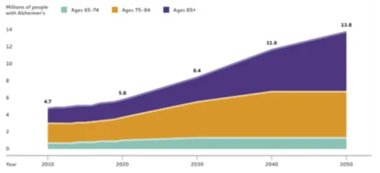
Figure 1.2: Projected number of people of 65 and older
Projected number of people age 65 and older in the U.S. population with Alzheimer’s dementia 2010 to 2050[4]
bound to bed and unable to feed themselves. The cause of death is usually an external factor, such as an infection or pneumonia.
At the start of the progression of the neuronal degeneration, the brain tries to compensate and contrast this derivation letting the patient to continue to live as normal but, as soon as the damage spreads and more neuronal areas starts to fall the brain compensation can no longer sustain the changes and the subtle cognitive decline will be exposed. This state, called mild cognitive impairment (MCI), is common in people older than 65 years old and the 38% of the MCI cases will develop a Dementia or Alzheimer Dementia (AD) in 1-5 years.
Alzheimer disease affects 4.5 million of Americans, by mid-century, the number of living people with Alzheimer dementia in the United States is projected to grow to more than 10 million, reported in the “Alzheimer’s disease in the US Population census”[7], as shown in Figure 1.2, this drastic growth will require a major effort by individuals who can attends to another person’s health needs, usually called Caregivers.
Caregiving often includes assistance with one or more activities of daily living (ADL) which are the actions of the everyday life, what people normally do in daily living including any activity, such as feeding themselves, bathing, dressing, working, and leisure. The caregiver also needs significant ability in performing instrumental activities of daily living (IADL), which requires more advanced level in all performance areas. IADL generally requires use of executive functions, social skills, and more complex environmental interaction than ADLs like take care of others or pet’s; child
Table 1.1: ADL and IADL category
ADL IADL
Functional mobility Care of others Self-feeding Care of pets Eating(Swallowing) Child rearing
Dressing Communication management
Personal hygiene Community mobility Grooming Financial management
Bathing Health management
Toilet hygiene Religious observance Sexual activity Safety maintenance
Sleep/rest Shopping
Personal device care Meal preparation and clean up
rearing; communication management such as telephones or mails; digital assistants or driving[8].
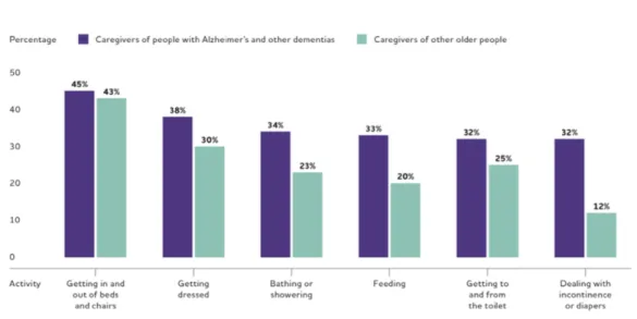
The Figure 1.3 shows how an individual affected from AD or other type of dementia will require more assistance from the caregivers with respect to regular elderly people and this will directly traduce into more costs, time and long-term daily care.
The personality of patients undergoes through several changes as a result of the brain degeneration; they can become confused, suspicious, depressed, fearful or anxious. They may be easily upset at home, at work, with friends or in places where they are out of their comfort zones. According to Elbert et Al.[9], this changes could affect how to perform the ADLs in ways that can be very difficult to tolerate for family members becoming one of the most challenging to take care of. This slowly but constant deviation of behavior with respect to the usual one is defined as behavioral drift.
As symptoms spread and grow in gravity, the required care can result into an increased emotional stress and depression for the caregivers, new or badly-escalated latent problems and, at the end, depleted income and finances due in part to disruptions in employment and payment for additional service of health care. As shown in Figure 1.4 on page 5 the cost for health care for the treatment of Alzheimer disease for people over 65 years old is over than $ 250 Billion in the United States during the 2017.
1.1 Alzheimer and Dementia 5
Figure 1.3: Difference in caregiving between Alzheimer’s and older people
Proportion of caregivers of people with Alzheimer’s or other dementias versus caregivers of other older people who provide help with specific activities of daily living, United States,
2015. Data from “National Alliance for Caregiving and AARP” [10].
Figure 1.4: Cost of care by payment sources for Americans with AD of more than 65 years old.
“Other” payment sources include private insurance, health maintenance organizations, other managed care organizations and uncompensated care[4].
Total cost: $ 259 Billion [B]
51% 17% 22% 11% $ 131 B Medicare $ 44 B Medicaid $ 56 B Out of pocket $ 28 B Other
1.2
Problem definition
Since there is no cure from dementia, the ultimate goal of the care provided by caregivers is to extend as much as possible the maintenance of cognitive abilities, to decelerate the progression of neuronal degeneration and, through a series of specific daily activities, to encourage the development of a natural brain compensation. Keeping the patients active with daily activities is therefore a prerequisite of the long term treatment centers, thus, in order to create a stimulating environment, that is also able to accommodate people and make them feel at home, it is required to design a new type of health care infrastructure.
Yvonne Van Amerongen, one of the six founders of the gated model village of Hogeway, explains how the idea was born[11]:
“It was 1992 and Hogewey was being run as an ordinary care home: wards, common rooms where 20 people sat watching TV, doing nothing, waiting for medication, for meals. It wasn’t living. It was a kind of dying. This isn’t how I’d like to spend my last days, how I’d wish my father to
spend his last days. ”
Hogeway is the first village in the world exclusively designed as a pioneering care facility for people affected by dementia, located in the city of Weesp, Netherlands. As a gated model village, Hogeway is a self-contained community where inhabitants can freely walk and interact with each other in wide open spaces; every structure of the facilities is specifically created to meet their needs, freeing the inhabitants to the burden of feeling slaves of the disease[12].
The service offered by the doctors is hidden from the sight of guests and inhabitants due to the fact that every caregiver is blended with the daily living of the village. Behind shop assistants, hairdressers or bartenders are concealed, even if without their regular white coat, professional caregivers that are ready to assist the guests and to help in the process of correcting behavioral drifts.
Health care facilities like the mentioned Hogway necessitate to have the minor number of caregivers as possible, in order to maintain the independent life of the inhabitant; thus they need to implement specific technological systems to support and simplify the activities of caregivers and to achieve the safety of the inhabitants. Considering the dimension of the facility, the unconventional freedom of the patients and the limited amount of human resources, the activities of the caregivers have to be
1.3 Thesis contribution 7
simplified through the use of a system developed specifically for the supervision of the structure
Moreover, a constant monitoring may be useful to obtain a complete analysis comprising of medical data resulting from clinical exams (e.g. electrical activity of the heart, blood pressure, oxygen saturation), medical history and also an extremely accurate description of the activities performed as a daily routine. To ensure a complete picture of daily activities, it is also necessary to trace the social interactions among the inhabitants to better understand how the mental processes of communication and collaboration between individuals evolve in order to find anomalies or sudden changes in personality and habits.
1.3
Thesis contribution
The aim of this thesis is the design and implementation of a Localization Indoor System capable of tracking the position of the inhabitants in “ Il Paese Ritrovato”, the gated model village in Monza[13] through the use of a special bracelet able to emit a unique identifier via Bluetooth signal. Bluetooth receivers are installed in all the rooms and significant point of interest in the village such as the garden, hairdresser, cinema or the church; the antenna is capable of reading the unique identifier that the bracelet constantly sends in order to collect the position of the inhabitants.
The caregivers of the facilities could not be able to constantly monitoring every patient by sight due to the fact that inhabitants can freely walk inside the village thus the system is able to identify the exiting path and notify the caregivers when someone eventually approach towards the exit points of the facility.
The system collect data related to position that can lead to analysis the “attendance” of the environments and points of interest in the village, social interactions between people and the count of daily movement; essential data that can be use to define behavioral drift and to provide a better support for the medical therapies.
It is possible to highlight some of the main component of the system:
• Bluetooth Bracelet: Is a 3D-printable plastic bracelet that contains a Bluetooth Transmitter that uses the iBeacon protocol, devoleped by Apple[14]. iBeacon is based on Bluetooth low energy capable of transmit a universally unique identifier picked up by a compatible antenna.
data. Each antenna is installed and connected via wired Ethernet into the network of the facility to transmit the position data to the Localization Server. • Localizaiton Server: All the acquired positions are sent to the server where they
can be stored and analyzed. The server is also responsible for the maintenance of the notification system that can generate a specific notify in order to support the care of a specific patient.
1.4
Thesis structure
Next chapters are structured as follows:
Chapter 2 shows the state of the art of the common methodologies used in Localization Systems.
Chapter 3 describes the architecture of the system and the main hardware compo-nents used in the experimental phase.
Chapter 4 describes how the localization system works. All the phases necessary to the configuration of the system.
Chapter 5 summarizes the results obtained and explains some possible future developments for the system.
Chapter 2
State of the art
Localization is the process that determines physical position (with respect to some coordinate system) or symbolic location of an object or human being.
In this chapter is presented the State of the Art for what concerns Localization Systems focusing on Local Positioning Systems.
In the following sections is presented the general taxonomy of Localization Sys-tems, the techniques necessary to the parameters estimation and the localization methodologies used for compute the target’s position.
2.1
Localization system taxonomy
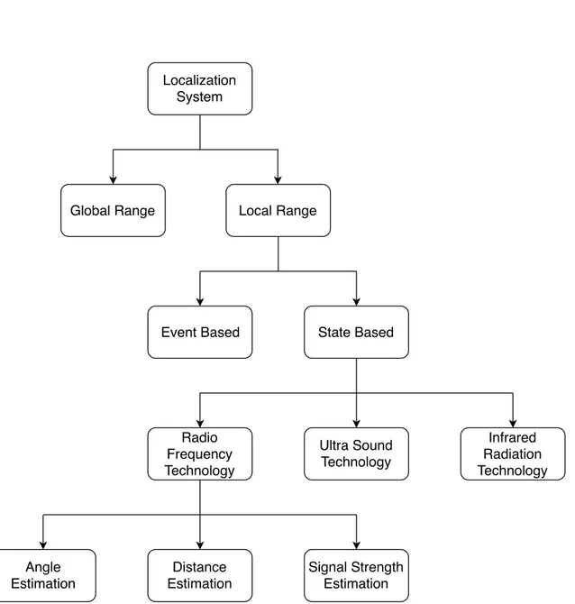
The Localization Systems can be divided into several categories according to the taxonomy shown in Figure 2.1. The first classification is focused on the operative range of the Localization System and can be divided into two categories: Global Positioning System (GPS) and Local Positioning Systems (LPS).
2.1.1
Range
The Localization Systems can be divided according to the environment in which they operate:
• Global: the Localization Systems that work in a global range are called Global Positioning Systems and are used in a wide range of applications like transport, navigation and assistance to guide, synchronization of telecommunications net-works, and geodetic survey. GPS is particularly suitable in outdoor positioning
Localization System
Global Range Local Range
Event Based State Based
Radio Frequency Technology Ultra Sound Technology Infrared Radiation Technology Angle Estimation Distance Estimation Signal Strength Estimation
Figure 2.1: The classification refers only to the type of systems that was considered in this thesis.
2.1 Localization system taxonomy 11
but the performance dramatically decreases in urban environments, due to walls and buildings, and in underground environments where the satellites signal is too weak to cross the obstacles making the system ineligible for indoor situations. The GPS concept is based on the known position of GPS specialized satellites. The satellites have a daily time synchronization with each other in order to mantain the clock precision. GPS satellites continuously transmit data about their current time and position. A receiver monitors multiple satellites and solves equations to determine the precise position of the receiver and its deviation from true time.
• Local: the Localization Systems that can be used in a local range are called Local Positioning Systems. LPS is particularly focused on estimating a target’s position in a closed and well-defined environment, thus it needs to have a set of fixed receivers which have a limited range, hence requiring the receiver to be near to these. These receivers are scattered around the localization space in order to create a set of reference positions that can also be used to provide a precise position inside a closed facility like shopping malls, hospitals, airports or university campuses. The development of an LPS needs to take into account a complex set of challenges such as the creation of small devices able to track the targets without line of sight due to the presence of obstacles like trees, mountains,walls or doors.
Considering the main topic of this thesis, the following sections are focused on the classification of the Local Positioning Systems.
2.1.2
Typology
The Local Positioning Systems (LPS) can be divided into two different types accord-ing to their capability of triggeraccord-ing some actions after the receivaccord-ing of an external activating event or their capability of acquiring precise information that can describe the environment. The first system is called Event Based while the latter is called State Based :
• Event based: defined as Localization Systems that can manage actions that, if accomplished, lead to a change in the target position. An Event Based system estimates the current position of a target based on its last determined position,
and incrementing that position based on the characteristic of the triggering event. Event based systems provide very accurate directional information, but one of the main disadvantages is that the inaccuracy of the process is cumulative, so the error in the estimated position grows with every iteration. The reason is that the new positions are computed entirely from the previous state of the measure.
• State based: defined as localization systems that use receiver devices able to scan the area in order to acquire information that can describe the surrounding environment. The collected data represents the condition of the system in that specific moment and a variation of this condition determines a change in the state of the system. This change is considered as a change of the target’s position while different sequential changes can be considered as a movement.
The following section, according to the goal of this thesis, is focused on the State Based LPSs that can exploit different technologies.
2.1.3
Technology
The State based positioning system can be classified by the technology that can be used in order to retrieve information:
• Ultrasound (US) is a technology inspired by the bats echolocation and operates in the low frequency band; ultrasound signals are used to find the position of emitter targets. The ultrasound signal has several advantages such as a slow propagation speed, a negligible penetration in walls and a low cost of the transducers. The accuracy achieved by ultrasound is typically of a few centimetres. Ultrasound localization systems suffer from interference of other ultrasound waves or the reflection propagated from the collision with materials like metal. For example, SNoW Bat developed by Baunach et al. [15] is a US system optimized for fast and precise localizations.
• Infrared radiation (IR) is a technology with an infrared spectral region that has been used in various ways for detection or tracking of objects or persons. System based on IR use line of sight communication between transmitter and receiver, with immunity to interference from source lights. The device can be small and portable, but an IR based localization system has some
2.2 Parameters estimation 13
disadvantages such as interference from the fluorescent light or the sunlight, expensive hardware and maintenance cost. Commercially available IR tracking systems such as Optotrak[16] and Firefly[17] mainly target medical and motion capture applications
• Radio frequency (RF) is a technology used due to some specific characteristic of the radio waves such as the ability to penetrate through obstacles like buildings, walls or human bodies.
Radio waves are a type of electromagnetic radiation with wavelengths in the electromagnetic spectrum longer than infrared light and they are generated by radio transmitters and received by radio receivers. RF based systems have a larger coverage area and need less hardware comparing to other systems (e.g the IR works only with a clear line of sight between emitter and receiver). The following section is focused on the specific parameters that need to be estimated by Radio Frequency Localization Systems in order to find a target’s position.
2.1.4
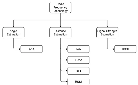
Estimated Parameters
Regarding the radio frequency based localization systems, it is possible to classify them according to the type of parameters they must estimate in order to localize the target. This parameters are the Angle, the Distance, and the Signal Strength:
• Angle: defined as the geometric angle between the propagation direction of an incident wave from the transmitter, and one other reference direction of the receiver, which is called orientation. This Localization System uses a complex set of antennas in order to estimate the angle of the received signals.
• Distance: defined as the numerical values of how far apart the emitters and the receivers are. The receivers need to have a fixed and well known position inside the localization space in order to accurately estimate the distance. • Signal Strength: defined as the received power output of the transmitters.
2.2
Parameters estimation
The estimation technique that can be used in Radio Frequency LPS in order to estimate the parameters for the positioning procedure can be classified, according to
Radio Frequency Technology Angle Estimation Distance Estimation Signal Strength Estimation AoA ToA RTT RSSI RSSI TDoA
Figure 2.2: Classification of the estimated parameters for State Based Local Positioning System, using Radio Frequency technology.
the parameters estimation, as shown in Figure 2.2.
The following sections are focused on the estimation techniques that are used to evaluate the parameters of: Angle, Distance and Signal Strength
2.2.1
Signal strength
The Received Signal Strength Indicator (RSSI) is a measurement of the power of a received radio signal, is expressed in dB-millivolts per meter (dBmV /m) and the values are typically in the range between -100 for a low signal level and 0 for a hight signal level. For very low-power systems, such as beacons or mobile phones, the signal strength is expressed in decibels above a fixed reference level of one milliwatt (dBm).
2.2.2
Angle
The estimation of the angle requires to compare the direction of the signal by two or more sensors that use directional antennas, which are able to radiate or receive power in specific directions. These receivers have increased performance and are less influenced by interference from unwanted signal sources because they can adopt an interpolation of the Lines of Bearings (LoBs). All the approaches for measuring
2.2 Parameters estimation 15
bearings provide, for each transmitter, a LoB respect to transmitter own axis and require multiple sensor array elements, which can increase the cost and the size of the device. The term bearing refers to an angle measurement with respect to another object.
Angle based Local Positioning Systems have their defects due to the fact that accuracy strongly depends on the possibility of correctly reading the neighboring emitting nodes and thus, gain a correct line of bearing.
Angle of Arrival: is defined by Peng et Al.[18] as the technique that estimates the angle between the propagation direction of an incident wave and one other reference direction. Orientation is represented in degrees in a clockwise oriented direction from a reference position that can be the geographical or the magnetic North. When the orientation is 0◦ or pointing to the North, the AOA is absolute, otherwise, relative.
2.2.3
Distance
Estimating the distance between the transmitter and the receiver can be done in several ways, taking into account the propagation time of the signal or the RSSI.
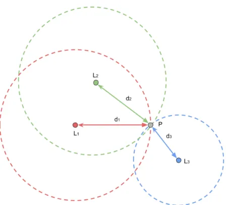
• Time of Arrival (ToA): is based on the accurate synchronization of the arrival time of a signal transmitted from a source to several receivers. In ToA, the signal needs to be tagged with a timestamp related to the instant time in which it is transmitted; The receiver computes the distance between itself and the transmitting source using the transmission delay and the speed of the signal. ToA method requires a greater knowledge of the transmission start times, thus all receiving sensors and the transmitting beacons are accurately synchronized with a precise and unique time source. ToA is one of the most accurate distance estimation because it can easily filter the multipath effect due to the significantly importance of the timestamp[19]. The time based systems require a precise time source used for synchronization of the devices time and also require an additional server for the computation of the time delay.
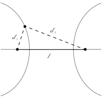
• Time Difference of Arrival (TDoA) is a time based methodology that is different from the ToA because it doesn’t require the time source of synchro-nization between the sensors and, also, remove the transmission of the start time from the emitters [20]. A TDoA based system needs to have at least two
d
1d
2l
Figure 2.3: The δd = d2 − d1 can be computed with the difference time of arrival of
the two signal. This produce an hyperbolic curve on the localization space.
emitters with fixed position, and a receiver that needs to be able to tag the signal with a timestamp, that represent the receiving time of the data. Once the signal is received at two reference points, the difference in arrival time can be used to calculate the difference in distances δd between the target and the two reference points:
δd = c × δt
where c is the speed of light and δt is the difference in arrival times at each reference point. In two dimensions, this leads to the following equation :
δd = d2− d1 =
p
(x2− x2) − (y2− y2) −
p
(x1− x2) − (y1 − y2)
where (x1, y1) and (x2, y2) are the known positions of the receivers and (x, y)
is the position of the target. Using nonlinear regression, this equation can be converted to the form of a hyperbola which is defined as the geometric locus of the points of the plane such that the difference in distances from two fixed points is constant.
2.2 Parameters estimation 17
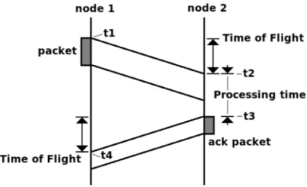
Figure 2.4: Computation of the flight time from node 1 to node 2 and backwards. Measure the time of flight path of the signal from transmitter to receiver and backwards.
• Round Trip Time (RTT): is a time based methodology that estimates the dis-tance by computing the time of flight of the signal traveling from the transmitter to sensors, and then the backward path as shown in Figure 2.4, where:
RoundT ripT ime(RT T ) = 2 × timeof f light
distance = RT T
2 × c =
(t4− t1) − (t3− t2)
2 × c
RTT uses only one node to record the transmitting and arrival times removing the disadvantages of the ToA to have the synchronized time source requirements for the sensors. One of the drawbacks of this estimation is range measurements to multiple devices that need to be carried out consecutively which may cause latencies for applications where devices move quickly.
• Proximity: is the RSSI-based estimation technique that exploits the attenuation of the signal strength with the travelled distance to estimate the distances separating the emitters from the receivers. These techniques exhibit favourable properties with respect to power consumption, size, and cost. Nevertheless, it is important to highlight that distance estimation using RSSI can be really challenging, since the measurements of signals’ powers could be significantly altered by the presence of additive noise, multi-path fading, shadowing, and other interferences. The Friis transmission equation is a formula used to calculate the ratio between the power received by an antenna and the transmitted power
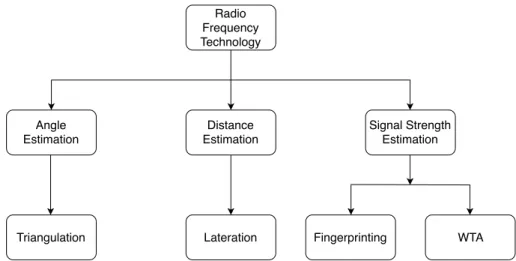
Radio Frequency Technology Angle Estimation Distance Estimation Signal Strength Estimation
Triangulation Lateration Fingerprinting WTA
Figure 2.5: Classification of the main localization methodologies that can be used in order to compute the position of a target. Each methodology requires different set of estimated parameters.
giving a certain distance between the two sensors.
Pr =
Pt× (Gt× Gr) × c2
4πRf2
Where Pr is the received power, Pt is the transmitted power, Gt and Gr are the
transmitted and received gains of the antennas, which represents the directivity and electrical efficiency. f is the frequency of the signal, c is the speed of the light and R is the distance between transmitter and receiver.
2.3
Localization methodology
To acquire the estimated parameters of the radio frequency based LPS is possible to adopt a series of methodologies in order to compute the exact position of the target. The Figure 2.5 shown the division of the localization methodologies by the estimated parameters they require.
2.3.1
Angle
The methodology that computes the position of the target from the estimated angle is called Triangulation and it uses the geometric properties of triangles. Triangulation based methods are techniques that determine the Angle of Arrival (AoA) of a signal
2.3 Localization methodology 19
Figure 2.6: The triangulation method uses the angle between the lines of bearings and the orientation of the receivers in order to estimate the position of the target as reported by Zahid et Al[19].
emitted by an unknown source and received by multiple base stations. The purpose is to find the angle between the Lines of Bearing (LoBs) and the reference orientation of a fixed source. The term bearing refers to an angle measurement with respect to another object as shown in Figure 2.6.
2.3.2
Distance
The methodology that computes the position of the target from the estimated distance is called Lateration; it is the process of determining absolute or relative locations of points by measurement of distances, using the geometry of triangles or circles as shown in Figure 2.7. The absolute distance between the transmitter and the receiver produces a circle in the localization space; the intersection between three or more curves produces the exact position of the target.
Unlike measurements of absolute distance, multilateration computes the exact position within an hyperbolic curves and requires multiple measurements: a second measurement taken to a different pair of stations will produce a second curve, which intersects with the first. When the two curves are compared, a small number of possible locations are revealed, producing the position of the target.
Figure 2.7: The Trilateration method uses the distance between the unknown transmit-ter to multiple receivers in order to estimate the position. The target is positioned on the circumference of the circles, in particular the exact position is in the intersection point of the three circles.
2.3 Localization methodology 21
2.3.3
Signal strength
There are two localization methodologies that compute the target’s position through the use of the signal strength indicator:
• Fingerprinting is a localization methodology that takes place after the installa-tion of the fixed transmitting elements in the environment, such as Wi-Fi access points, Bluetooth Low Energy beacons, or LED lighting fixtures. Fingerprinting requires to record the measurement of the signal characteristics, such as received signal strength indicator (RSSI). Often a grid system is used where the grid line spacing is 1.5 or 3 meters and readings are taken at each grid line intersection point.
This information is stored in the fingerprint database. Each entry in the database is a mapping between a location and a position fingerprint. In the case of a large facility, multiple receiving source can be simultaneously used in the different parts of the facility. Once the fingerprint database has been established, when users run the indoor positioning system, the readings taken by the user’s receiver are compared to the antecedently stored readings in the fingerprint database, and compared in order to determine the user’s position. In most facilities, it is not feasible to utilize pure signal triangulation only, due to the various types of interference that can occur with each technology, such as signal reflection, and attenuation of signals by structural elements of the facility.
Because facilities change and evolve over time, it is important to determine the intervals at which facility fingerprinting will have to be repeated.
• WTA: is a “Winner Takes All” methodology and is one of the simplest po-sitioning methods to implement. It provides a symbolic and relative location information while determines the position of the target by it’s cell of origin (CoO). When the system detects the signal, it simply computes the position on top of the antenna that receives the strongest signal which represent the CoO of the signal. The RSSI can be pre-processed with a filtering method, since it can help in smoothing the target’s position, reducing the estimation error. The accuracy of the CoO approach is strongly related to the density of antennas and the deployment path spreads across the facility. When low cost is a priority over accuracy, localization using signal strength and distance measurements are the most used.
Chapter 3
System architecture
The localization system designed for “Il Paese Ritrovato” is composed by Bluetooth antennas that act as receivers of the information broadcasted by Bluetooth beacons; the received data are sent to a central Web Server which is in charge of the estimation of the position with a RSSI distance detection methodology for each beacon.
The caregiver needs to be able to observe the inhabitant positions and to receive alert notifications or requests for assistance from other colleague in dangerous situations. The computed localization data are requested from the mobile app via HTTP message to the Web Server. In order to collect valid and specific information about the position of each inhabitant without violating the privacy of the user, a non invasive system is required. The Figure 3.1 shown the main component of the architecture which are Bluetooth beacon transmitter, Bluetooth receiver, central web server, and the mobile app.
This chapter provides a description of the hardware and software solutions that have been selected to design the system.
3.1
Beacon
The beacon is a Bluetooth based device which trasmits in the iBeacon[14] format; it consists in a Bluetooth source transmitter that can be unequivocally identified through a unique ID code. An iBeacon constantly advertises a packet of informations, as shown in the Table 3.1, that contains:
• Universally unique identifier (UUID): is the unique code that is assigned to a beacon; it is used to identify a common characteristic of the beacons, like
Antenna
Antenna
Server
Data
Bluetooth LAN Ethernet Internet
. . .
Beacons
Antennas
Server
Mobile App
Figure 3.1: The system is divided into four main component: Bluetooth beacon, Bluetooth receiver, web server, and mobile app
the producer or the owner;
• Major: is a number that is assigned to iBeacons, in order to create a group of beacons that are working in the same operative area such as the same floor or building;
• Minor: is a number that unequivocally identifies of the beacon within its group of work.
In order to customize the emitted packets, it is possible to change the values by using a dedicated mobile application that also allows to set the transmission frequency and the power of the emitted signal; changes of this two parameters affect the battery life. For example, transmitting a packet with a period of 100ms (Apple iBeacon preset) with the default power of transmission, an iBeacon has an expected battery life up to 28 weeks. The power of the transmitted signal can be configured in a range from -100 to 0 dBm and, when an antenna receives a data packet from a beacon, the measure of the RSSI is forwarded to the server in order to estimate the position of the target.
Since the RSSI is a value that can be attenuated by the water of human bodies, the beacon needs to be carefully positioned on the inhabitants in order to avoid signal distortion and guarantee a significant signal for the positioning system. Beacons can be powered using coin cell batteries hence, they are small enough to be encapsulated
3.2 Antenna 25 Table 3.1: The UUID, major and minor values provide the identifying information for the iBeacon. Generally speaking, this information is hierarchical in nature with the major and minor fields allowing for subdivision.
Provided by Apple [14]
Field Size Description
UUID 16 bytes Can be define by the developer.
Major 2 bytes Can be used to define larger group of iBeacon. Minor 2 bytes Can be used to further define a subset of a group.
inside a plastic bracelet that can be attached on the wrist of the inhabitants. The selected bracelet for the initial sperimental phase of the project is 3D-printed in plastic, which means it cannot alter the Bluetooth signal and the presence on the wrist is non intrusive as can be inside the clothes. Another possible solution, currently under evaluation by the “La Meridiana cooperative”, is the possibility of sewing a beacon within clothes or attach it under the shoes.
3.2
Antenna
The system relies on a set of antennas that measure the strength of the received Bluetooth signal emitted by the beacons; this indicator (i.e, RSSI) relates the distance between the emitter and the receiver, providing an estimation of the position.
The localization algorithm, used by the system, requires to send the RSSI to a Web Server which is in charge of the estimation of the beacon’s position. Therefore, the antennas need to be Bluetooth Low Energy (BLE) compatible in order to scan the environment and to host computational power for pre-processing the data before forwarding it to the server.
Raspberry Pi[21] is a credit card-sized computer which can be used in electronics projects that has a built-in Bluetooth module based on BLE, WiFi module, USB and Ethernet ports. This computer is a low-cost solution that can be used as an antenna, and in order to map the facility, it can be easily positioned in the counter top of each inhabitant room, receiving and collecting information broadcasted by the iBeacons.
As shown in Table 3.2 and Table 3.3, the Raspberry Pi is a low-power device that can be powered through Power over Ethernet (POE) allowing the appliance to be powered using the same cable that connects it to the Ethernet data network of the central server.
Table 3.2: The Raspberry Pi used as antenna for the system is the Pi 3 Model B. The table shows the required power source[21].
Recommended PSU current capacity
Maximum total USB current draw
Typical bare-board active current
consumption
Voltage
2.5A 1.2A 400mA 5V
Table 3.3: The Raspberry Pi used as antennas for the system is the Pi 3 Model B. The table shows the power consumption of the board during boot, idle and stress[21].
Case Average Value Max value
Boot 0.35A 0.75A
Stress 0.85A 1.34A
Idle 0.30A
-The antenna hosts a Web Server that is implemented with Flask [22], a framework that is used to design and implement web applications including web services, web resources and web APIs. Flask provides standard way to deploy web applications and aims to automate the common activities performed by web server applications. It does not require particular tools or libraries but it supports extensions that can be perfectly implemented as if it were built inside the framework itself. Extensions exist for object-relational mappers, form validation, upload handling and several common tools and are updated far more regularly than the core Flask program[22]. Flask is available in Python, a flexible high-level programming language that implements a dynamic type environment and automatic memory management; it aims to achieve an highly readable code giving a strong significant to white spaces and adopting the off-side rules for the indentation of the lines. Finally, Python provides Flask as an installable package from the community making the code development easier.
Each antenna of the system has been carefully arranged in order to map the entire facility. Each apartment is equipped with several Raspberry Pi3, concealed under the roof, placed in the private rooms, in the corridors and in the common areas such as the kitchen or the living room.
3.3
Server
The server is the central node of the positioning system and it collects the information sent from the antennas. It is connected to the same LAN of the Bluetooth receivers
3.3 Server 27
via Ethernet port and it runs the localization algorithm that estimates the position of each Bluetooth beacon in the structure. It runs a web server implemented in Flask that allows the reception of localization data packets from the antennas trough an HTTP message. This data are permanently stored inside an SQL database managed by Flask migration and Flask SQL alchemy that is a Python SQL toolkit and Object Relational Mapper (ORM) that provides to the application developers a full suite of well known enterprise-level persistence patterns, designed for efficient and high-performing database access, adapted into a simple and Pythonic domain language[22]. The ORM technique allows to store data and data-management tasks with an object-oriented approach that can be non-scalar values. For example The Implemen-tation of the storage function are usually wrapped in an API in the programming language in order to expose methods that interact with the data storage in a simpler way.
The following code execute a query written in SQL using a database engine: Algorithm 1 SQL query
1: sql = ”SELECT *FROM persons WHERE id = 10”
2: cmd = new DbCommand(connection, sql)
3: res = cmd.Execute()
4: name = res[0][’NAME’]
In contrast, the following code uses an ORM API function to query the data: Algorithm 2 ORM query
1: p = repository.GetPerson(10)
2: name = p.getFirstName()
The framework exposes filtering and querying functionality, allowing subsets of the storage base to be accessed and modified. The code below queries for people in the database whose ID value is ’10’: The stored information are computed by a Python Algorithm 3 ORM filtering options
1: p = Person.Get(Person.Properties.Id == 10)
algorithm that use the Proximity methodology, which estimate the position of the target on top on the antenna with the highest measurement of RSSI.
Figure 3.2: The tag displayed on a map in the mobile application.
3.4
Mobile App
The mobile application is a primary support for the work of the caregivers, at the beginning of each work shift, the operator logs in the application and selects his/her daily work tasks and immediately be notified on the position of patients that are assigned to him/her. The mobile application is the only tool that can be used by caregivers to have access to the positioning system. It is implemented using an open-source development kit for mobile application, created by Google,[23] called Flutter [23]. Flutter aims to craft beautiful and high-quality native apps thanks to the flexibility of the widgets used to built the interfaces. Flutter’s widgets incorporate all the mobile platform differences features such as scrolling, navigation, icons, and fonts to provide full native performances on both iOS and Android. The Flutter foundation library provides basic classes, tools and functions that can be used to
3.4 Mobile App 29
implement the communication with the engine of the framework; it is written in Dart, a general-purpose programming language used to build web server and mobile applications for the Internet of Things devices. It uses an object-oriented approach with a C-like syntax that can transcompile into Javascript if it is needed. The server sends the localization data informations for each inhabitant to the mobile phone as HTTP messages and the mobile application displays the position of the resident on a map as shown in the Figure 3.2.
The mobile application is deployed on the mobile phone of the caregivers, provided by “Il Paese Ritrovato”; this smartphone displays the personal and clinical data of the inhabitants and allows the operator to send alert notifications to other caregivers in order to receive assistance.
Chapter 4
System description
The positioning system aims primarily at ensuring safety and welfare and reducing caregiver responsibilities by tracking the inhabitants position and providing daily behavior and social interaction during their activity routines to the caregiver. In order to obtain this information, the system is designed to autonomously work in a non-invasive way, and it does not require any interaction from the caregivers. The inhabitants of “Il Paese Ritrovato” are not able to perceive the existence of a system that constantly tracks their movements and profiles their activities and social interactions. The eventual abnormal behavior of the habitants is immediately notified to the responsible caregivers via the mobile application that represents the only possible interface between the caregivers and the system. The main idea is that the localization system needs to have a minimal impact on the life of inhabitants.
The RSSI distance detection methodology is used to estimate the location of the target on top on the position of the Bluetooth source that emits the strongest signal, hence, the target is a Bluetooth enabled receiver that measure the signal and acquire its RSSI, which is an indicator of the strength.
The implemented localization system, however, uses a reverse approach in which the mobile targets are iBeacons, which constantly emits a unique identifier, while the antennas are the fixed receivers, correctly arranged in the environment in order to map the facility.
4.1
System configuration
The configuration of the system requires an initial definition of the physical structure of the environments. The operation allows the division of the facility into one or more smaller section called areas; each of this zones have a particular meaning inside the life of the village and can be seen as place of aggregation and social interaction with therapeutic purposes. Their main characteristics are name and description; an example of area can be a church, a supermarket, a garden or a theater. Each area of the village can be subsequently divided into smaller sections which are called subareas; they are highly focused on the aspects of the activity which they can host. The subdivision can be intended as a geometric or surface division, such as a building that can have one subarea for every floor. Each subarea is characterized by a name and a description and can contain one or more antennas disposed with the purpose to geometrically map the entire surface of the subarea. Subareas can also contain rooms which can be assigned to the residents of the village. It is required to upload, inside a subarea, an explicative image in which the antennas can be positioned; this image is used by the system to localize the tags and to display their corresponding positions on the map. Example of subareas are the first floor of the facility, the changing room of the gym or the hobby modeling shop inside the supermarket.
A second phase consists in the configuration of the antennas which are called as devices when they are connected via Ethernet port to the LAN of the facility.
In the last phase it is possible to insert users in the system and to assign them a specific profile (e.g. a profile for the caregiver’s role corresponds to a role shift allocation to an apartment).
4.1.1
Device configuration
The registration of an antenna as a device of the system can take place in any moment during the regular activities of the localization system and can be resolved as an automatic or a manual configuration.
Automatic configuration It is a well-defined procedure that can be divided into two subsequent tasks:
1. Device acquisition: the admin of the system can start the antenna configuration mode on the server that enables the broadcast transmission of a packet via User
4.1 System configuration 33
Figure 4.1: In the central web server of the system there is a special tab for the devices configuration.
Data Protocol (UDP) that expose the server IP to all of the Bluetooth antennas of the LAN network.
The antenna configuration mode needs to be stopped when the last antenna installed in the environment has been correctly identified and configured into the system. If this mode is not stopped, the acknowledge packets will be contentiously sent through the network causing a decreased performance of the server and of the LAN network itself.
2. Device registration: when an antenna boots on for the first time, it starts to scan the LAN network in order to acquire the identification packet from the server. This packet contains all the relevant information about the server, and since the antenna is aware of the server IP address, it is possible to start the registration procedure. The antenna sends a registration request to the server through an HTTP request; the server generates an id device that will be the unique identifier of the antenna inside the system. The device registration phase needs to be repeated for each antenna that wants to be connected to the system. Since the system needs to work with a large number of devices used to map the multitude of POIs in the facility, it can be difficult to manually configure the antennas during the first configuration, therefore it is possible to execute this automatic procedure in any moment of the life time of the system in order to configure new
Figure 4.2: In the antenna web server it is possible to set the server IP and request a manual registration with the underlined command.
devices.
Manual configuration Each antenna that is powered and connected to the LAN network exposes a Web Interface that allows an hand-operated configuration in which it is possible to manually send a registration request to the server.
The first thing to do for achieving a manual configuration is to set the IP address of the central server of the localization system as shown in Figure 4.2. This manual configuration doesn’t require the activation of the antenna configuration mode on the central server and can be done in any moment during the regular activities of the system. The central server responds with an HTTP message that contains the new Id device for the antenna.
The device list of the system, shown in Figure 4.1 is composed by all the antennas that are allowed to send data to the central server. If an antenna is not registered in the system, the data sent are always discarded by the server.
4.1.2
Fixed Station configuration
The Fixed Station (FS) represents a spot on the map of the facility at which it is associated a physical device in order to acquire localization data for that particular point as shown in Figure 4.3. They have a name which is a human readable description of the FS and they can be assigned to rooms and subareas of the facility.
The position of the FS is fixed and dragged inside the subarea map by the admin, that can also connect them with each other in order to create a graph structure that represents all of the possible pathways inside the facility. The node of the graph are the FSs while the arcs are called routes as shown in Figure 4.4.
4.1 System configuration 35
Figure 4.3: The admin can arrange the position of the FS by a drag and drop tool on the central web server of the system. Every FS is a Point of Interest of the village.
• Room FS: they are positioned in the bedroom of each resident, it requires a strong accuracy in order to avoid false positive situation in which an habitant is wrongly located inside a room. For this reason, the radius of the room FS is set to be minor than the one of the adjacent corridor FS.
• Corridor FS: they are placed in corridors and pathways of the facility. They represent the need to geometrically map places that do not have a particular meaning of positioning and that can be considered as obligatory steps to move from one point of interest to another. If they are connected to room FS they need to have a bigger radius in order to give a significantly relevance to the localization data they sent.
• virtual fence FS: they are positioned alongside the exit points, they represent the last localization source of the village after which the tag can be considered escaped from the facility. They need to be as accurate as possible in order to avoid a generation of false alerts, if they are approached by inhabitants, the localization data they sent becomes a priority for the central server. It is impossible to connect a virtual fence FS with a room FS due to the different
Figure 4.4: The routes can connect one or more FS witch each other in order to create a dense node graph that is used to reduce the cross-walking phenomena of the target’s signal.
4.1 System configuration 37 coupled.png
Figure 4.5: All of the FS must be coupled with a device in order to allow their transmission of localization data packets.
purpose and the different generation of localization data.
The association between the device and the FS is called coupling request and is performed by the admin of the system as shown in Figure 4.5. The server sends an HTTP message to the selected device and authorizes it to transmit location data as shown in Figure 4.6 It is possible to couple only one device at a time. During the coupling request it is possible to set the radius ( Figure 4.8) parameter for the device that influence the data which are sent from that specific FS; this particular parameter is used to enlarge or reduce the operative area of the antenna and, thus, affects the value of RSSI of the tags that lies in the area.
The caregivers of “Il Paese Ritrovato” believe that the presence of people in rooms can be a good indicator for the analysis of behavioral model and social interaction, thus increasing the radius of the corridor FS, for example, decreases the probability that the patient is mistakenly positioned in the room if its actual position is in the corridor (Figure 4.7).
The FSs of the system can have an identification name that represent a human readable identification of Point of Interest (PoI) since it is not used by any operator,
Couple FS
Admin Server Device
[idDevice := NULL] ALT
Id FS
200: OK
Figure 4.6: The coupling request, started from the admin, is designed to associate a specif FS with a device of the system.
Figure 4.7: The Corridor FS needs to have a stronger radius parameter than the Room FS in order to reduce the probability of mistakenly localize the target inside a room.
4.1 System configuration 39
Figure 4.8: The FSs have a property called radius which allow the admin to define their operative area.
its only purpose is to help the admins during the configuration phase.
4.1.3
User configuration
The Admin of the system has access to the user list which is a comprehensive list of all the actors that can actively or passively receive a benefit from the system functionalities. Each user can have an associated Tag which represent the Bluetooth beacon that constantly transmit informations; the Tag is always associated to one user, most of the time to an inhabitant, and it represents the person that needs to be localized inside the village (Figure 4.9). Tag can be intended as a representation, inside the system, of the Bluetooth iBeacon 3D printable bracelet that are in use at “Il Paese Ritrovato” (Figure 4.10), it is assumed that the user does not remove the
beacon from the bracelet due to the light weight and the non invasive property. The Admin has the responsibility to assign to the users one of the following
Figure 4.9: The Tag can be associated with a User, in particular a Resident, in order to allow the system to localize that specific inhabitant.
categories:
• Admin: it is the manager of the system, it has access to the configuration panel of the system; it can add or delete areas, subareas, FSs, rooms and, also, other users from the system; it is in charge of the registration of new devices.
• Supervisor : it is the chief of the operator users. It associates Tag to users and it is responsible for the creation and the maintenance of the profiles, the most important part for the active use of the localization system.
• Operator : it is in charge of the village; it is the caregiver of the habitants and it uses the mobile application of the localization system in order to use the system and to monitor the position of the inhabitants for which they are responsible. • Resident : it is the inhabitant of the village; it does not need to interact with
the system in order to gain beneficial effects.
It has an associated Tag that is used inside the system as the logical identity that needs to be localized inside the facility.
The resident user, even if it does not have the authorization to enter the system, has a username and password attributes in preparation for future uses that may be requested by the village.
During the very first configuration of the system, only a pre-scripted user is available as the only Admin of the system. Every other Admin, who will be created
4.1 System configuration 41
Figure 4.10: The realtime tab of the central web server shows the detected Tags inside the operative area of the antennas.
Figure 4.11: The profile is composed by a group of people with some common characteristics and represent a working shift for the operator that are going to take care of that specific group during that day.
after the first one, will not be able to modify or delete the first user of the system (the original Admin).
4.1.4
Profile configuration
The residents of the facility are to many to be handled by the small number of caregivers, hence, they need to be divided into smaller groups in order to be better manageable. A profile can represent a group of users, created by the supervisor as shown in Figure 4.11, that lives in the same district of the village; in this way the operator can easily monitor the situation of a specific part of the village, havin a constant update on the status of those people in order to assess their position and movement.
The supervisor provides to the inhabitants of the village a multitude of physical and intellectual activities in order to stimulate the brain and to slow down the decay of their cognitive abilities thus, there are psychologists, personal trainers, social workers and many other professional caregivers who can share their proficiency and skill in order to provide a better support to the activity of daily living.
share common interests, but also schedules, behaviors or that have same particular needs and therefore it is possible to delineate a common profile for this residents that is not strictly correlated to the place in which they live in.
The profile is not only assigned to residents, in order to classify their characteristics, but is also assigned to operators that are responsible for that particular characteristics, so it is possible to associate the caregivers to the inhabitant which they care for. For example, it is possible to have a profile that represents a living district with residents and the relative operators or a profile that represents the same district during the night shift with different operators and the same residents.
The profile list is created by the supervisor at any moment; the supervisor can assign the users in order to create a group which has meaning within a well-defined context like the shift of the operator or common activities. Other examples of profiles are first floor night shift, first floor morning shift, second floor women, morning gym class, psychomotor for district A, garden class for district B.
4.2
Functioning of the system
Upon arrival at the residence each inhabitant is provided with a 3D-printable bracelet containing an iBeacon technology Bluetooth device. The inhabitants that will be hosted in the structure are all affected with early-stage Alzheimer’s disease, thus they are able to perform normal daily activities independently. Therefore, each resident is aware of being localized during the whole stay in the structure. The localization is made possible thanks to the creation of a fit network of receivers carefully arranged in the environment.
These antennas are responsible to intercept the beacon messages broadcasted by the beacons; the strength of the received packet - Received Signal Strength Indicator (RSSI) - is subsequently used by the system to estimate the position of the patients. The antennas continuously scan the environment in order to acquire the unique code that identify the Bluetooth beacons, the measurement of the RSSI is preprocessed for each tag with an application of a median filter for noise reduction. The filtering time window of this preprocessing phase can be set by using a threshold determined during the configuration of the device.
The resulting data is periodically transmitted to the central web server via an HTTP request containing the following message:
![Figure 1.1: Percentage of population aged 60 years or over by region, from 1980 to 2050 as reported in “Alzheimer’s disease facts and figures”[4].](https://thumb-eu.123doks.com/thumbv2/123dokorg/7505522.104810/18.892.145.662.212.547/figure-percentage-population-region-reported-alzheimer-disease-figures.webp)
![Figure 2.6: The triangulation method uses the angle between the lines of bearings and the orientation of the receivers in order to estimate the position of the target as reported by Zahid et Al[19].](https://thumb-eu.123doks.com/thumbv2/123dokorg/7505522.104810/35.892.270.669.206.509/figure-triangulation-bearings-orientation-receivers-estimate-position-reported.webp)