SCIENTIFIC ARDUINO PROGRAMMING
Arduino programming for scientists
A free addendum to ”Scientific Programming”
GIOVANNI ORGANTINI
Sapienza Universit`a di Roma & INFN–Sez. di Roma
Contents
zero Introduction 5
zero.1 What is Arduino?. . . 6
zero.2 What this booklet is intended for . . . 7
zero.3 How to use this booklet . . . 7
zero.4 Supporting this work . . . 7
due How Arduino works 9 due.1 Arduino basic architecture . . . 9
due.2 Program development . . . 11
due.3 Using Arduino on Linux . . . 13
tre Arduino basic programming 15 tre.1 The first Arduino sketch . . . 15
tre.2 I/O with Arduino . . . 16
tre.3 Showing data . . . 18
quattro Program execution control 19 quattro.1 The selection structure . . . 19
quattro.2 The iteration structure . . . 20
sei Saving data 23 sei.1 Using Serial communications. . . 23
sei.2 Connecting to the Internet . . . 27
sei.2.1 Configuring the Ethernet shield . . . 28
sei.2.2 Using the Ethernet shield to collect data . . . 30
sei.3 Using an SD card . . . 34
sette Arduino specific functions 37 sette.1 Setting up pins . . . 37
sette.2 Writing and reading digital pins . . . 38
sette.3 timing . . . 42
sette.4 Analog pins . . . 42
otto Measuring with Arduino 45 otto.1 Voltages . . . 45
otto.2 Distances . . . 50
otto.3 Temperature. . . 54
otto.4 Light . . . 56
otto.5 Magnetic field . . . 57
1
scientific arduino programming – Vers. March 4, 2016
© 2015 Giovanni Organtini, Sapienza Universit`a di Roma & INFN–Sez. di Roma
This work is licensed under a Creative Commons Attribution– NonCommercial–NoDerivs 3.0 Unported License. You can find all the details about this license onwww.creativecommons.orgfor details. You are free to copy, distribute and transmit this work. You must attribute the work as a work of Giovanni Organtini ([email protected]), who does not endorse you or your use of this work. You may not use this work for commercial purposes. You may not alter, transform, or build upon this work. You can support the development of this manual by making a donation onPayPalusing the e–mail [email protected].
This work was partly supported byFarnell Element14who kindly provided some of the parts described in the text.
Contacts:
Prof. Giovanni Organtini Sapienza Universit`a di Roma Dip.to di Fisica
P.le Aldo Moro, 2 00185 ROMA (Italy)
Tel: +39 06 4991 4329 Fax: +39 06 4453 829 e–mail:[email protected]
Technical note
This book has been written usingLATEX, an open source, high–quality typesetting ap-plication. Schematics have been realised usingfritzing, an open source application to draw electronics schemas.
Arduinoitself is an open source initiative. We strongly support this kind of projects, not only because their open nature makes them inexpensive, but mainly because the open standard guarantee a very high quality of the tools (they can be contributed by thousands of developers) and mostly because they provide a formidable tool for learning. We invite you too to support the open initiatives you use: you can do that in a variety of ways. You can, for example, donate money to the developers, to recognise their effort, or you may prefer to buy products from those who make them available to anyone as open source projects. That is the case of Arduino, for example. You can certainly find
Arduinoclones that are cheaper than those you can get from theArduinoofficial store, or from other official stores of legal Arduino–compatible boards, but saving few dollars does not help much, in fact. On the other hand you create a damage to those who are trying to change the standard business model based on hiding information and patents. As you can read on theArduinowebsite, you can download and use their reference designs and ”you are free to use and adapt [those designs] for your own needs without asking permission or paying a fee”. We believe this is really a revolutionary paradigm with respect to the commonly adopted one, that is suitable to increase dramatically both knowledge and welfare all around the world.
Chapter zero
Introduction
This paper is an introduction to Arduino programmingfor students who learned C on ”Scientific Programming” by L.M. Barone, E. Marinari, G. Organtini and F. Ricci– Tersenghi [1], edited by World Scientific (or its italian counterpart ”Programmazione Scientifica” edited by Pearson). ”Scientific Programming” is an innovative textbook on computer programming thought for science students, who does not care about writing Hello World! on a screen, but are interested in using a computer as a tool to do science. Chapter 0 of ”Scientific Programming” is about how computing and programming is important for a scientist. Chapter 1 is about information representation (there is no need for a Chapter uno here, since information is represented exactly in the same way onArduinoboards).
One of the authors of ”Scientific Programming” (Giovanni Organtini), started to teach
Arduinoprogramming in his course about computing and programming for physicists, being theArduinoboard a great resource for physicists and engineers. As well as in the case of C++ he wrote these notes in the style of [1], keeping the same chapter structure and a very similar style. In this booklet, chapters have the same numbering of [1], except the numbering is given in italian, as a tribute to the italian origin of theArduinoboard, invented by Massimo Banzi and his colleagues in Ivrea (TO), Italy1. Each chapter uses notions that can be learned in the corresponding chapter in [1]. In fact,Arduinocan be programmed in C++ language, but at a very basic level it can be thought as a dialect of the C language, sharing mostly the same syntax. You can learn some basics of C++ reading another free addendum to ”Scientific Programming”, by the same author, available on the Scientific Programming website. However, you can obtain good results just knowing some C language: the chosen language for ”Scientific Programming”. For these reasons, some chapter number is missing: the corresponding content is exactly the same of [1].
Students wishing to learn someArduinoprogramming without owning a copy of [1] shall not be scared: those students should not have too much difficulties in learning how to write programs forArduinoif they are able to write C programs.
1The nameArduinocomes from their haunt in Ivrea: a pub called after the name of an ancient king
of Ivrea whose name was Arduino.
6 CHAPTER ZERO. INTRODUCTION
zero.1
What is Arduino?
Arduinois an inexpensive, commercially available electronic board with a microcontroller and some I/O capabilities. It exists in various versions, that share the same, simple pro-gramming language. The huge success ofArduino, with respect to other microcontroller boards, was due to the fact that both hardware and software were released as Open Source projects: you can read, study and even expand its capabilities both in terms of software as well as in terms of hardware. All the information are shared under the
Creative Commons Attribution-ShareAlike 3.0 License.
You can useArduinofor many different purposes: from teaching to home automation1,
from scientific purposes to commercially available devices, as well as to have fun (you can be surprised about the many ways in which people useArduino). Thanks to its very simple interface to I/O ports you can control many different devices, both digital and analogical. For example, you can measure voltages using analog inputs or drive a DC motor using a digital output port. You can as well switch on and off an LED or a relay using digital output ports and transmit/receive data to/from more complex devices such as GSM boards. The job of (at least a large part of) physicists is to measure something:
Arduinois then a very useful tool both to control measuring apparata or as a device to take measurements by itself (for many purposes it can be accurate enough to replace professional, and expensive, instruments).
The design ofArduinoboards is such that its form factor is (almost) independent on theArduino version. The first Arduinoboards used a microcontroller whose chip took a somewhat large space; nowadays the same chip is available in a much smaller form factor, however the size and the shape of the Arduino board is still the same (and in fact there is plenty of free space on it). That choice has one big advantage: third party manufacturers can easily design, produce and sell boards that extend the functionalities of any Arduino, and users can easily connect them to it. In fact, those board, called
shields have a set of pins that just plug into the corresponding pins on the Arduino
board and no specific electrical connection is needed to make them work. You can buy, for few bucks, boards designed to provide Internet or GSM connectivity, GPS capabilities, stepper motor control and much more.
UsingArduino, anyone with a very basic knowledge of some elementary electronics is able to build complex electronic devices effortlessly: the complexities of the electronics are translated into software, hence even people not used to work with analog and digital devices such as diodes, transistors, operational amplifiers, integrated circuits, logic ports, etc., can realise interesting projects. Tutorials can easily be found on the Internet for various tasks: given the Open Source nature of the project, people are encouraged to share their projects with others so anyone can benefit of other’s experience.
1The author, for example, built a device able to switch on and off home appliances remotely just
ZERO.2. WHAT THIS BOOKLET IS INTENDED FOR 7
zero.2
What this booklet is intended for
Scientific Programming aims to fast, precise, efficient and complex computation. All of these characteristics are addressed in our previous publications [1] [2].
This booklet is intended as an introduction toArduinoprogramming from the point of view of the microcontroller programming. It does not include details about hardware if not strictly needed. It is not even a collection ofArduinoprojects: those provided are just meant as examples.
zero.3
How to use this booklet
As stated in the introduction of the chapter, this booklet cannot be considered complete and consistent by itself. It must be used at least in conjunction with another book teaching scientific programming in C. The best, of course, is [1], since this booklet is modeled upon it and is using the same chapter structure.
The way in which this booklet can be used depends wether or not you already knows C or not. If you don’t, study the C language using [1]. As soon as you study a given chapter, look for the corresponding chapter in this publication, read it and make the proposed exercises.
If you already know C, proceeds with this book, after refreshing your mind having a look to the corresponding chapters on [1], to recall the numerical techniques or language details involved.
Please also consider that this is an experiment. Any comment concerning the content of the present publication will be greatly appreciated. You can communicate with us via e–mail writing [email protected].
zero.4
Supporting this work
You can support the development of this manual by making a donation onPayPalusing the e–mail [email protected](but not if you are a student of mine, at least until you have successfully passed your exams).
In particular, details about projects specific for physicists will be added in future, upon reception of a reasonable amount of donations. We are, in fact, using donations, to buy new devices to be tested. Once tested, programming details will be added to this book.
Donations are intended to support the development of this publication, then we con-sider donations to be fair in the range 1–5 euros (5 euros already being a big donation), not more.
If you are a teacher you can be interested in using Arduinoin your school to make physics experiments in lab. Designing scientific experiments to be done withArduinois the main topic of this manual. Donations will make more and more affordable experiments
8 CHAPTER ZERO. INTRODUCTION
to appear on this publication. Your pupils may want to learn aboutArduinoanyway. You can support this work collecting donations among your students and making a unique payment. Consider the possibility to print and sell the printed manual to your student as a tool for raising some funding for your lab: you can do that, according to the license, provided that you are a non–commercial entity.
All donors will be included in a mailing list and notified as soon as a new, improved version of the manual is made public. Of course, there is no need to donate more than once: if you were included in the mailing list you stay there forever, unless you ask to be removed.
If you make a donation, we only collect your e–mail address. The only purpose is to notify you when a new version of this document will be made public. We will not share any information about you with others. You are free to ask to be removed from our list at any time, just by sending us an e–mail [email protected].
Chapter due
How Arduino works
Chapter 2 of ”Scientific Programming” is about computer architecture and programming languages. In this chapter we provide a brief description of theArduinoboard, from the point of view of its architecture as a computer. You need to understand how a computer works and what is intended for terms like machine language, high–level programming language, compiler, etc..Arduinois in fact a computer much like the one described on Chapter 2 of [1]. Before reading this chapter, it is advisable to review the content of that chapter of [1], if you can.
Whenever we mention anArduinoboard, we always refer to theArduinoUNO: the most widely used version of it. There are other versions ofArduinoboards that differ for the size of the memory, the microcontroller used on board, the number and the type of the I/O ports and other capabilities, or the form factor. However, all of them share the same first principles.
due.1
Arduino basic architecture
The core of theArduinoboard is a microcontroller chip known as theATmega328. The Atmega328 is in fact an 8 bit computer just as the one described in the first chapters of [1]: once switched on, its CPU loads a byte from a predefined memory location and interpret it as a statement. What follows is interpreted according to the content of such a byte. Contrary to the computers to which you are familiar with, the ATmega328 does not run any operating system: the usage of the resources is completely under the control of the programmer. You cannot rely on the operating system to prevent wrong memory usage, overflows, underflows and any other error. Moreover, that CPU can only run one task at the same time (you may remember that this is true for all the CPU’s, however the operating system distribute the operation time to various tasks in such a way you have the impression that many programs run at the same time on your computer).
A fresh Arduino has an empty memory, hence the first byte loaded by the CPU correspond to the statement nop: no operation. Before using Arduinoyou must then load its memory with an executable program, i.e. a sequence of bits, the first of which
10 CHAPTER DUE. HOW ARDUINO WORKS
is interpreted as a statement and executed. If the statement needs parameters to be executed, they are taken from the following bytes in the memory. Once the execution of a statement has been completed, the CPU loads the successive byte in the memory and interprets it as well as a statement. If you switch off yourArduino, the memory is not lost. The sequence of bytes loaded into it are kept in a non–volatile memory, such that when you switch it on again, the program starts again from its beginning.
The timing for CPU operation is provided by a 16 MHz clock, while the power can be provided through a dedicated power jack as well as through its USB interface (see below). For operation,Arduinorequires an input voltage between 7 and 12 V (voltage regulation is provided on board, so you just need an inexpensive power supply for that). On board, both a 5 V and a 3.3 V regulated output are provided to the user, too, from which you can drive a maximum current of 50 mA.
Arduinomemory is of three types: a flash memory, where the program is stored, of 32 kB; a static random access memory (SRAM) of 2 kB, where the CPU stores and manipulates the variables used in the program; and an erasable read only memory (EEP-ROM) of 1 kB where the programmer can store data that must survive the switch off (as the flash memory, where the program is stored). Compared to modern computers, who often bear as much as few GB, a total of 35 kB seems ridiculous, but in fact it is enough for most purposes. Because of the lack of an operating system, the memory usage is under your own responsibility: if you run out of memory or you try to access a non existing memory location, your program may behave strangely and it is very difficult to debug it. You must always keep the number of variables under control in your program. The ATmega328 CPU is connected to 14 I/O digital pins (numbered from 0 to 13), 6 analog inputs and a USB port. A digital pin is an electrical connection that can have two logical states: 1 and 0, or true and false or, as in theArduinojargon, LOW and HIGH. When put to LOW, the corresponding pin is at the ground potential: if you measure the voltage between the ground and the pin you get zero. If the pin is set to HIGH the voltage between the pin and the ground is 5 V.
Pins 0 and 1 are used for serial transmission and reception: on those line theArduino
board can communicate with shields on it using a serial protocol. Serial protocols are communication protocols in which each bit is transmitted/received one after the other. Pins 2 and 3 can also be used as interrupts. An interrupt is an electrical signal that interrupts the current CPU program upon the occurrence of a given event. Interrupts exists also on computer’s CPU’s1. Once an interrupt is detected, the CPU saves its
state in the memory and abandon the execution of the program, jumping to execute the
interrupt handler: a short and fast piece of software needed to serve the interrupt.
Upon completion, the CPU resumes the status it had before serving the interrupt and restart the execution of the program.
Pins 3, 5, 6, 9, 10 and 11 are PWM (Pulse Width Modulation) pins (labelled with a 1For example, on computers running Windows, pressing the Ctrl-Alt-Del key combination,
gener-ates an interrupt (a software interrupt) and all tasks are suspended until the interrupt handler (the task manager) is finished.
DUE.2. PROGRAM DEVELOPMENT 11
Figure due.1 Arduino UNO as it appears on the front and back side of the board. Note the map of Italy on the back side.
~) and provide also some analog capabilities (see Chaptersette). Correspondingly, their memory counterparts contains values between 0 and 255.
Pin 13 is also connected to an LED on board. When the pin is LOW the LED is off, while if the pin is HIGH the LED is on.
Besides standard use as digital I/O ports, pins 10, 11, 12 and 13 provide a mean to communicate with external peripherals.
Analog inputs are labelled A0 through A5: each of them provides a resolution of 10 bits, i.e. they convert any voltage from 0 to 5 V to a number between 0 and 1023 that can be accessed in the memory.
All the systems are mounted on a board whose size is 60.6× 53.4 mm2 and weights
as low as 25 g (Fig.due.1).
The board also carry a USB A/B connector through which you can connect it to a computer for communications. The USB connection also provides power to Arduino
when connected to a computer, so that you don’t need an external power supply.
due.2
Program development
A program for an Arduino is, as any other program for a CPU, a sequence of bits in
machine language. In order to make the life of a programmer easier, the Arduino team
has provided a high–level programming language, a compiler and a communication tool to deploy the machine code on theArduinomemory.
All those tools are included in an IDE (Integrated Development Environment) freely available on the Arduino website for download: identify the version needed for your preferred operating system and install it. It appears, as many computer applications, as a tool with a menu and some windows. One of those windows is used to edit the program, called a sketch inArduinojargon. Sketches are written in C++, but you can think them as C programs, since the basic syntax is exactly the same.
12 CHAPTER DUE. HOW ARDUINO WORKS
Figure due.2 The Arduino IDE appears as a window in which you can type the text of the program, called sketch.
You can compile your sketch within the Arduino IDE (Fig. due.2) clicking on the
verify button at the top left corner of the window: the compilation process translates each C++ statement in the sketch into one or more machine language statements for the Atmega328 processor. Once compiled, the executable sketch can be transferred into theArduino memory through the USB cable, upon clicking on the upload button . You may need to select the appropriate port from the menu, if there are more than one available. A transfer always trigger the invocation of the compiler, first. The sketch execution starts as soon as the transfer finish.
More capabilities are added to the basic language by means of external libraries provided by the Arduino team or third parties. Libraries can be included in the executable code, acting on the appropriate menu item. If needed, adding a library, automatically
DUE.3. USING ARDUINO ON LINUX 13
adds lines on the sketch to inform the compiler about the syntax of the new statements provided by the library.
due.3
Using Arduino on Linux
Few versions of Linux (such asUbuntu) are designed for not very experienced end users. Other versions, such asScientific Linux, however, are not: they are supposed to be used by people expert enough to understand some internals of the operating system. If you are reading this book, you probably are a scientist (or at least you aim to become a scientist) and most probably you are using a version of Linux not so user friendly1. In this case
you may miss some needed component.
In order to use theArduino IDEon Linux, you need to make sure you have the Java
Development Kit or JDK. Only after having it installed you can run the arduino
script included in the bundle. Search for jdk or openjdk in the packages available for your distribution. For example, in systems using yum for package management:
yum s e a r c h yum
You will get something like:
[ o r g a n t i n @ p c 1 ~] $ yum s e a r c h jdk L o a d e d p l u g i n s : refresh - p a c k a g e k i t , s e c u r i t y = = = = = = = = = = = = = = = = = = = = = = = = = = = = = = = = = = = = = = = = = = = = = = = N / S M a t c h e d : jdk = java -1.6.0 - o p e n j d k . x 8 6 _ 6 4 : O p e n J D K R u n t i m e E n v i r o n m e n t java -1.6.0 - openjdk - d e m o . x 8 6 _ 6 4 : O p e n J D K D e m o s java -1.6.0 - openjdk - d e v e l . x 8 6 _ 6 4 : O p e n J D K D e v e l o p m e n t E n v i r o n m e n t java -1.6.0 - openjdk - j a v a d o c . x 8 6 _ 6 4 : O p e n J D K API D o c u m e n t a t i o n ...
Then, to install:
yum i n s t a l l java -1.6.0 - o p e n j d k
When you run the IDE, it may happen that many error messages appear on the terminal, complaining you have no permission to create locks. That’s why normally Linux prevent standard users to write on places where the system stores important information for its working. You can either run the IDE as root, or better you can, as root, give yourself the rights to write in the proper place. TheArduinoIDE needs write permission on /var/lock. To give them you can use the system command chmod in a shell running in a terminal:
c h m o d o + rwx / var / l o c k
1In italics, since there is nothing friendly in hiding details to users: this is what is usually intended
14 CHAPTER DUE. HOW ARDUINO WORKS
It means change file mode for file /var/lock such that others (not in the group of the super user) (o) should be given (+) permissions to read (r), write (w) and execute (x) that directory (executing a directory makes it possible to cd to it).
On most Linux distributions USB devices are created as soon as you plug the cable into a USB slot. Connecting an Arduino to your computer using the USB cable may then result in the creation of a device called /dev/ttyACM0 or so, or /dev/ttyUSB0 or so. These devices are needed for the communication betweenArduinoand the computer and must be properly set. In the IDE menu you can see the available ports in the Tools/Port menu item. The port in use must have the right permissions, too. If you can’t connect to any port, you may alter permissions (still as root) with
c h m o d o + rw / dev / t t y A C M 0
There is no need to set the x permission in this case. If the device is deleted when you disconnect yourArduino, each time you reconnect it you must set permissions again. A possible workaround, in this case, is to include the user under which you run the Arduino IDE, in the same group of the device (usually dialout). You can check what are the owner and the group to which the device belongs using the Linux terminal with the command
ls - l / dev / t t y A C M 0
You should see something like
crw - rw - - - - 1 r o o t d i a l o u t 31 , 2 Jan 5 1 4 : 1 0 / dev / t t y A C M 0
that means that /dev/ttyACM0 is a character device (c) belonging to user root of the dialout group. The owner and any other user in the same group have read and write permissions. Others have no rights (the last group of three dashes: ---). If you want to be able to read and write from/to this device, you must belong to the dialout group. You can add a user username to another group using the system command
u s e r m o d - a - G d i a l o u t u s e r n a m e
This way, each time you plug yourArduinoto your computer, the device is created on the fly and you can seamlessly use it, belonging to the group authorised to read/write from/to it.
Chapter tre
Arduino basic programming
In Chapter 3 of ”Scientific Programming” we teach how to write a very basic program able to make something interesting for a scientist. In this chapter we illustrate how to write a very basic sketch forArduinousing its IDE. In this chapter no usage of I/O ports is made, but for the USB connection. The syntax of theArduinolanguage is exactly the same of the C–language syntax, hence we are not going to discuss it. We concentrate on the particular aspects of theArduinolanguage, in which you can use all the concepts you learnt about C programming: variables, operators, statements, types, constants, etc..
tre.1
The first Arduino sketch
The Arduino language does not need a starting point as in C–language, where you are forced to define the main program. Indeed, when the program starts, it loads what is called an object in Object Oriented Programming OOP [2] into the memory. Objects in OOP belong to classes. For each object of the same class a state is defined as a set of attributes or members that can be thought as variables, being represented as a collection of data of various types in the memory. The state of an object can be manipulated by methods: a collection of statements intended to perform a given oper-ation to alter or provide the state of the object. If you are not familiar with OOP, you can think to the state as a collection of variables and to the methods as a collection of functions.
Here we assume you are familiar with the C language learnt on [1], so we adopt a slightly incorrect language to describe how a sketch is organised, that however is con-sistent with the notions given in the corresponding chapter on [1] and works quite well, even if not formally correct.
AnArduinosketch is self contained in one file in which, contrary to the C–language, you need to define at least two blocks of statements: one called setup() and another called loop(). Variables to be shared between the two blocks must be defined outside them, as if they were global variables1.
1In fact they are not: they are the members of the object loaded into the memory at start. As such, 15
16 CHAPTER TRE. ARDUINO BASIC PROGRAMMING
As soon as the program starts, the statements collected within the setup() block are executed: they are intended to initialise the content of the variables at start as well as to configure theArduino ports behaviour. Once the execution of the setup() block is finished,Arduinostarts executing statements in the loop() block. After execution those statements are executed again forever (hence the name loop).
1 vo i d s e t u p () { 2 ... 3 } 4 5 vo i d l o o p () { 6 ... 7 }
Listing tre.1 An Arduino basic sketch.
Both the setup() and loop() blocks are defined as void blocks, i.e. they do not re-turn anything (see Listing tre.1). You can use standard preprocessor directives such as #define, #ifdef, #ifndef, #endif, etc. In particular, we strongly encourage you to define constants as preprocessor symbols (not as variables, since they eat the SRAM memory).
tre.2
I/O with Arduino
Arduinodoes not have a port to connect to a screen, nor to a keyboard: they are not needed on this type of devices. I/O pins illustrated in Chapterdueare meant to provide some input and output capabilities to some electronic devices: in practice you can only read and write voltages to that ports. There is no I/O like the one you are used to in computer programming, however in some cases it is useful to read some message on screen (e.g. during the debugging phase).
In order to makeArduinodisplay some text message or to provide some input from the keyboard you can connect the board to a computer via the USB cable. Messages are displayed on a dedicated window called the serial monitor. Such an interface is not intended for complex functions, and has a very basic behaviour, even more basic than terminals. You can activate a serial monitor by selecting the corresponding item in the main menu of the IDE. At start, the serial monitor may behave strangely, showing (apparently) random characters. Those characters are those remained in the serial buffer flushed to the monitor when connected.
Text I/O capabilities are provided through the serial communication using the USB cable, hence there is no printf statement in the language. Instead, there is an object called Serial providing methods to read and write to the serial line. You can think to these methods as statements in C language, whose name contains a dot.
TRE.2. I/O WITH ARDUINO 17
If you want to print a text message on the serial monitor window, you can use the Serial.print() statement, whose syntax is
S e r i a l . p r i n t ( < message >};
where <message> is a variable or a constant. The way in which the content of the message is displayed depends on its type. For example, writing
int i = 67;
S e r i a l . p r i n t (" the v a l u e of i is "); S e r i a l . p r i n t ( i );
S e r i a l . p r i n t ("\ n ");
makes the text the value of i is 67 appear on the serial monitor window. The first Serial.print statement1 contains a string constant as a parameter (specified by the characters " surrounding the text) and it is written as such. The second one contains an integer variables, whose content is read from memory and represented as a standard integer number on the screen. The last statement adds a newline character (note that it can be written even as Serial.print(’\n’), being \n a single character) after 67. You can print a text message ending with a newline also using the Serial.println statement that automatically adds a newline character at the end of the message as in
int i = 67;
S e r i a l . p r i n t (" the v a l u e of i is "); S e r i a l . p r i n t l n ( i );
In order to configure the speed of the serial communication, you need to setup the communication parameter before starting using the channel. To this purpose, use the Serial.begin(9600); statement, where 9 600 is the communication speed in bauds (a unit of speed in telecommunications). Such a speed can be any number among a range documented on theArduinowebsite, depending on your hardware. Usually 9 600 works well with any relatively modern computer.
Laboratory tre.1 I/O with Arduino
Write a sketch with few variables of various type and write its value on the serial monitor using the various forms of the Serial.x state-ments. Try putting the statements within the setup() block and within the loop() block and observe what happens in the two cases. Note that Serial.print tries to get the type of variable to represent it in the right way. For example, if ch is a character variable, try to print c and c+1: the results are different. Why? How would you write the character that comes after a given one in the ASCII table?
1Remember we are adopting an incorrect language here: Serial.print is not a statement, but a
18 CHAPTER TRE. ARDUINO BASIC PROGRAMMING
The Serial.read() statement returns the first byte available in the input buffer. Its usage is quite more complex with respect to scanf and is not described here (you must be familiar with the selection structure, first). On the other hand, its usage is not so frequent inArduinoprogramming and is not so important as on computers.
tre.3
Showing data
DespiteArduinodoes not have a screen, you can connect some display to it. There are few options for this: either you use an LCD display, or a TFT shield, i.e. a shield with a Thin Film Transistor LCD. Plain LCD displays can show up to four lines of text or so, while with a TFT shield you can display data with high resolution (typical resolutions are 160× 128 pixels and 240 × 320 pixels). They exist both in black and white and in colour versions and few models have also touch features.
TFT and LCD programming is not discussed in this version of this document: they will be available when we will reach the amount of donations needed to buy the corresponding hardware. SeeChapter zeroabout how to donate.
Chapter quattro
Program execution control
Chapter 4 of ”Scientific Programming” is devoted to the illustration of the structures used to control the program execution flow (logic management). Logic management on
Arduinois exactly the same as for C. There is no exception with respect to the C language structures. This chapter, then, is devoted to applications specific toArduino.
quattro.1
The selection structure
The selection structure is useful to test whether there are characters waiting to be read in a serial communication or not. Before using the I/O statements on the serial monitor you must be sure that the connection is up and running. Remember that there is no operating system onArduinotaking care of the resources usage, hence you can successfully compile and run a sketch trying to use serial communication, but it can behave in an unpredictable way if the communication channel does not exist and is configured properly.
The statement Serial.available() returns true if there are characters waiting to be read on the serial line, false otherwise. In order to test if characters are ready to be read from the line you can use something like
S e r i a l . b e g i n ( 9 6 0 0 ) ; ... if ( S e r i a l . a v a i l a b l e ()) { c h a r c = S e r i a l . r e a d (); S e r i a l . p r i n t ( c ); } ...
With Serial.read() you can only read one character: there is no equivalent of scanf(str, "%s") statement in the Arduino language.
20 CHAPTER QUATTRO. PROGRAM EXECUTION CONTROL
quattro.2
The iteration structure
The iteration structure, too, can be very useful in Arduino programming. Besides the usages to which you are familiar with, a quite frequent usage of the iteration structure can be found inArduinosketches and, in particular, in the loop() block. As stated in Chaptertre, the statements in the loop() block are repeatedly called in an infinite loop. If you need the sketch to stop completely its execution, you need to setup an infinite empty loop:
w h i l e (1) { // do n o t h i n g }
Another usage is to wait for characters on the serial line and build strings from those characters, like in c h a r ch = N U L L ; c h a r str [ 2 5 5 ] = { 0 } ; int i = 0; w h i l e ( ch != '\ n ') { if ( S e r i a l . a v a i l a b l e ()) { ch = S e r i a l . r e a d (); str [ i ++] = ch ; } }
In the code above, we define an array of characters whose elements are set to NULL. Then, we start reading characters from the serial line, as soon as they become available (Serial.available()). Once read using Serial.read(), characters are added to the string str, assigning the corresponding element in the array. The index of the next element (i) is updated and the loop is continued until the last read character is a newline.
Laboratory quattro.1 A better control of the serial monitor
Modify the sketch you wrote in Chapter tre to include control of serial communication availability. Each time you deploy a new sketch to Arduino, the serial monitor is closed, being the communication channel used to transmit the executable code to the Arduino flash memory. Before writing to the serial channel, check that someone is connected to it. To do so, you can write a loop in which you control the availability of characters to be read on the serial line: leave the loop, if so. Opening the serial monitor, the sketch should be blocked, waiting for characters to appear on the serial line. Send at least one character to it (just pressing the enter button is enough), then either discard the character or show it, and exit from the loop, continuing the execution of the sketch.
QUATTRO.2. THE ITERATION STRUCTURE 21
Laboratory quattro.2 Controlling the execution of the loop()
Define a variable whose value is set to zero at the beginning. The variable must be incremented at each execution stage (every time the loop() function is called. Show the value of the variable in the serial monitor. Use a for loop to change the value of another variable whose value is set to zero at the beginning of each loop() invocation and is incremented at each step for a number at your choice. Write both the number of times the loop() function is called and the value of that variable.
Use an iteration structure to change the way in which the loop() block is executed. In particular try avoiding it to be called more than one, two or ten times.
Chapter sei
Saving data
Pointers are illustrated in Chapter 6 of ”Scientific Programming”. Besides other uses, pointers are used to make data persistent in files. If you are using Arduino to take data in a physics lab or for any other application requiring data logging, you need some persistent storage, i.e. a way to, at least, write data into a file to be retrieved offline for analysis.
There are several ways to achieve the task: for example, one can transmit these data via Internet to some server who takes care of getting the data over the communication protocol and store them on disk; if you can write a program working as a client over a serial communication channel, you can send data over this channel using the Serial.xxx family of statements described in Chapters tre and quattro; another way consists of writing data directly fromArduinoto some external storage attached to it.
sei.1
Using Serial communications
Arduinouses serial communication to exchange data with a computer both when deploy-ing the executable program into its memory, as well as when usdeploy-ing the serial monitor tool. Of course, one can exploit this ability to write a program on a computer that sends/reads characters over the serial line to exchange data withArduino.
In principle serial communication is very easy: on the Arduino side just use the Serial.xxx functions, while the computer sees the serial channel as a file from which you can read characters using binary read/write functions (see Chapter 6 of [1]). How-ever, using a serial line requires some initial configuration that may sound difficult to beginners. Despite this textbook is focused onArduino programming, we include here few information about how to write a program on a computer to be used in conjunction withArduinoto establish a serial connection.
To fully understand the program, one need to know about bitwise operators, illus-trated in Chapter 14 of ”Scientific Programming” and about struct, the topic of Chap-ter 9. However, some copy and paste programming is acceptable even for a scientist, if at least the first principles are understood.
24 CHAPTER SEI. SAVING DATA
A serial communication implies to connect to the serial port: this is done using the open statement in C as in
int fd = o p e n ( s e r i a l p o r t , O _ R D W R | O _ N O N B L O C K );
where serial port is a string containing the filename corresponding to the port (on Linux, it is something like /dev/ttyACM0 or /dev/ttyUSB0, while on MAC OS X is something like /dev/tty.usbmodem1421). The O RDWR and O NONBLOCK constants are defined in fcntl.h, as open. The | character is a bitwise OR operator: it essentially perform the sum of the two values represented by the constants. Browse the fcntl.h file on your system to get their values. On our system, we found
# d e f i n e O _ R D W R 0 x 0 0 0 2 # d e f i n e O _ N O N B L O C K 0 x 0 0 0 4
The 0x characters preceding the values indicate that the values are expressed as hex-adecimal numbers (being bot less than 16 they coincide with decimal ones). The result of O RDWR | O NONBLOCK operation is 6 (0x0006 in hexadecimal), since the bitwise OR op-erator returns the sum of the operands expressed in binary, hence 0010 + 0100 = 0110. O RDWR is needed to open the file (the port) in both read and write mode, while O NONBLOCK tells the system that the open statement should return after connection without waiting for data becoming available on the port.
Serial ports can be configured to run at different speed (e.g. 9 600 baud). The speed is contained in a struct and can be set for input and output as
s t r u c t t e r m i o s t o p t i o n s ; ...
c f s e t i s p e e d (& t o p t i o n s , 9 6 0 0 ) ; c f s e t o s p e e d (& t o p t i o n s , 9 6 0 0 ) ;
where options is a struct called termios (the operator & returns the address of the struct) and 9 600 is the chosen speed. As shown on Chapter 14 of ”Scientific Program-ming”, a struct is a sort of complex variable. You can think about it as a composite variable whose components are ordinary variables or other struct variables. Each single component can be addressed as the name of the struct and the name of the component separated by a dot ., as in options.c ispeed, an unsigned long integer containing the port speed expressed in baud. Both the functions and the definition of the struct are in termios.h.
Once called, the functions above fill the struct with standard values, that can be modified acting on each struct component. There are many options to configure, but their full description goes beyond the scope of this book. Often, the default configuration of the port works well and most of the type you just need to disable the canonical mode flag. In canonical mode, devices provide data in form of strings terminated by a newline character (i.e., line by line). If you want to read single characters from the line you must disable the canonical mode with
SEI.1. USING SERIAL COMMUNICATIONS 25
c lflag is the component of termios defined as an unsigned long integer. It represents a binary coded set of flags (bits that can be either 1 or 0). ICANON is a constant, while the ~ character is a bitwise NOT operator. The &= operator combines a bitwise AND with an assignment operator. Indeed, what happens here is that the CPU reads the current content of toptions.c lflag and perform a bitwise AND operation between this value and ICANON; the result of this operation is in turn assigned to toptions.c lflag. In practice, toptions.c lflag is set (its value is 1) if canonical mode is active, 0 otherwise. According to the description given above, to put back the port in canonical mode, it is enough to be sure that the corresponding bit is 1, then
t o p t i o n s . c _ l f l a g |= I C A N O N ;
that performs a bitwise OR operation between the current value of toptions.c lflag and ICANON. Once toptions.c lflag has been assigned properly, its value should be transferred to the port with
t c s e t a t t r ( fd , TCSANOW , & t o p t i o n s );
Here, fd is the file descriptor returned by the open statement, TCSANOW a flag that instruct the port to change its properties immediately and &toptions is the address of the struct containing the actual configuration of the port.
1 # i n c l u d e < s t d i o . h > 2 # i n c l u d e < f c n t l . h > // n e e d e d for o p e n 3 # i n c l u d e < t e r m i o s . h > // t e r m i o s d e f i n i t i o n 4 # i n c l u d e < u n i s t d . h > // n e e d e d for r e a d 5 6 int m a i n () { 7 s t r u c t t e r m i o s t o p t i o n s ; 8 int fd ; 9 10 fd = o p e n ("/ dev / tty . u s b m o d e m 1 4 2 1 " , O _ R D W R | O _ N O N B L O C K ); 11 12 c f s e t i s p e e d (& t o p t i o n s , 9 6 0 0 ) ; 13 c f s e t o s p e e d (& t o p t i o n s , 9 6 0 0 ) ; 14 15 t o p t i o n s . c _ l f l a g &= ~ I C A N O N ; 16 t c s e t a t t r ( fd , TCSANOW , & t o p t i o n s ); 17 18 c h a r ch ; 19 c h a r buf [ 2 5 5 ] = { 0 } ; 20 w h i l e (1) { 21 int i =0; 22 do { 23 int n = r e a d ( fd , & ch , 1); 24 if ( n > 0) { 25 buf [ i ++] = ch ;
26 CHAPTER SEI. SAVING DATA 26 } 27 } w h i l e ( ch != '\ r ' && i < 2 5 5 ) ; 28 29 buf [ i ] = 0; // n u l l t e r m i n a t e the s t r i n g 30 p r i n t f ("% s " , buf ); 31 } 32 }
Listing sei.1 A program to read single characters from the serial line. The program prints each line received from Arduino on the screen.
You are now ready to read whatArduinowrites on the port according to your config-uration. A complete program to read data from Arduinois shown in Listingsei.1. The program read the serial line character by character. A line ends with a carriage return
\r. Listingsei.2provides an example on how to use canonical mode, instead.
1 # i n c l u d e < s t d i o . h > 2 # i n c l u d e < f c n t l . h > // n e e d e d for o p e n 3 # i n c l u d e < t e r m i o s . h > // t e r m i o s d e f i n i t i o n 4 # i n c l u d e < u n i s t d . h > // n e e d e d for r e a d 5 6 int m a i n () { 7 s t r u c t t e r m i o s t o p t i o n s ; 8 int fd ; 9 10 fd = o p e n ("/ dev / tty . u s b m o d e m 1 4 2 1 " , O _ R D W R | O _ N O N B L O C K ); 11 12 c f s e t i s p e e d (& t o p t i o n s , 9 6 0 0 ) ; 13 c f s e t o s p e e d (& t o p t i o n s , 9 6 0 0 ) ; 14 15 t o p t i o n s . c _ l f l a g |= I C A N O N ; 16 t c s e t a t t r ( fd , TCSANOW , & t o p t i o n s ); 17 18 c h a r buf [ 2 5 5 ] = { 0 } ; 19 w h i l e (1) { 20 int i =0; 21 int n = r e a d ( fd , buf , 2 5 5 ) ; 22 if ( n > 0) { 23 p r i n t f ("% s " , buf ); 24 } 25 } 26 }
Listing sei.2 A program to read text lines from the serial line. The program prints each line received from Arduino on the screen.
SEI.2. CONNECTING TO THE INTERNET 27
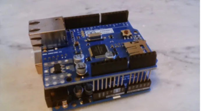
Figure sei.1 The Arduino Ethernet shield is a board that plugs on top of an Arduino board. This shield has an RJ45 connector to connect it to a plug via an RJ45 cord and a SD card slot. There exists shields with WiFi capabilities.
examples they are equivalent, since we assume thatArduinois writing text lines ended with a newline to the serial line.
Data read from the serial line can then be saved on your computer running the programs described above, for offline analysis. Using files on computers is the topic of Chapter 6 of ”Scientific Programming”.
sei.2
Connecting to the Internet
When collecting data, you may want to send these data over the Internet to be visualised and stored for future use. Data visualisation and storage is then demanded to a server connected to the Internet, receiving data from an Internet connected Arduino. Hence all the processing needed to render, visualise and store the data on disk is taken by the server and requires some standard programming skill (not necessarily in C: in most case you may want to use Java, Perl, Python or something similar). This side of the problem is out of the scope of this publication and is not covered here.
Of course yourArduino must be able to collect these data and send them over the Internet. For this you need what is called anEthernet shield: an Arduino shield able to communicate with other devices using the Internet protocols.
Ethernet shields exist in a number of flavours: some of them have an RJ45 connector to plug them to the Internet by means of a cable, some other have WiFi capabilities. Usually they carry an SD slot on board to host a SD card, too.
28 CHAPTER SEI. SAVING DATA
There exist also Arduino boards with Internet capabilities on board, such as the
Arduino YUN.
sei.2.1
Configuring the Ethernet shield
In order for any device to connect to the Internet, the device must acquire a unique identity on the network: the IP address. The IP address (IP stands for Internet Protocol) of a device is a unique identifier composed, in the IPv4 version of the standard, the most commonly used, of four bytes, each of which can have a value between 0 and 255. Few of them are reserved internationally and, in particular, subnetworks whose first two bytes are 192 and 168 are non–routable, i.e. packets sent over such a network cannot go beyond an Internet switch. In other words they can only reach those devices on the same physical network. Thats why devices in a home network usually have IP addresses like 192.168.x.y. The IP address of a device can be statically or dynamically assigned to it. In the first case, the device administrator tells the device its IP address: in this case the address is going to remains the same with time forever. A device not having a static IP address can ask for an IP address to any computer on the same network running as a DHCP
server (Dynamic Host Configuration Protocol). Depending on the configuration of the
server, available IP addresses can be assigned to the device randomly or based on the device identity.
Every physical device, in fact, brings a unique MAC (Media Access Control) address: a set of six bytes, usually expressed in the hexadecimal notation, as 5e:a4:18:f0:8a:f6. The MAC address is broadcasted over the network so that a DHCP server can choose if the request must be ignored, served using a randomly chosen address or with a fixed address. Having an IP address in not enough for a device to communicate with other devices: data packets must reach a special device, called the gateway, that knows how to send data to the recipient. The gateway, too, must be assigned an IP address and its address must be known to the devices aiming to communicate with others.
IP addresses can be associated to strings composed of a host name and a domain
name. All devices on the same network shares the same domain name, while host names
are unique. A DNS (Domain Name System) is a device able to associate the IP address of any other device to its host name.
The last piece of information needed to setup a network device is the subnet mask. This is a rather technical element, but we can think of it as a way to identify the range of addresses a device can reach directly through a gateway. It is usually in the form of an IP address (but it is not, it is a mask) and often equal to 255.255.255.0, meaning that all the devices on the same network share the first three bytes of their IP address.
We now have all the ingredients to connect our Arduinoto the network: first of all plug the Ethernet shield to the Arduino board (see Figuresei.2), then connect the shield to your router using an RJ45 cable. In order to configure the device you must know the MAC address of your shield (you can find it printed on the box or you can just invent it, provided it is unique in your network). Consider the excerpt of Arduino in Listingsei.3
SEI.2. CONNECTING TO THE INTERNET 29
Figure sei.2 An Arduino board with an Ethernet shield mounted on it.
1 # i n c l u d e < E t h e r n e t . h > 2 # i n c l u d e < SPI . h > 3
4 by t e m a c A d d r [] = {0 x5e , 0 xa4 , 0 x18 , 0 xf0 , 0 x8a , 0 xf6 }; 5 I P A d d r e s s a r d u i n o I P (192 , 168 , 1 , 6 7 ) ; 6 I P A d d r e s s d n s I P (192 , 168 , 1 , 2 5 4 ) ; 7 I P A d d r e s s g a t e w a y I P (192 , 168 , 1 , 2 5 4 ) ; 8 I P A d d r e s s s u b n e t I P (255 , 255 , 255 , 0); 9 10 vo i d s e t u p () { 11 E t h e r n e t . b e g i n ( mac , a r d u i n o I P , dnsIP , g a t e w a y I P , s u b n e t I P ); 12 }
Listing sei.3 Ethernet shield configuration.
Including Ethernet.h and SPI.h is mandatory: the files contain the definition of the classes used in the sketch. The MAC address is defined as an array of bytes, each of which is represented as a pair of hexadecimal digits (thanks to the 0x preceding each number). The IP addresses of the shield, the DNS and the gateway is given as an object of class IPAddress, as well as the subnet mask. The object constructor takes four arguments that represent the four bytes of the address. Our Arduino will acquire the IP address 192.168.1.67, in a network whose gateways address is 192.168.1.254; the gateway works also as the DNS in this case, while the subnetwork is restricted to those devices having an IP address like 192.168.1.x.
The Ethernet.begin(mac, arduinoIP, dnsIP, gatewayIP, subnetIP) call does the job: it configures the Ethernet shield as above (and, of course, it does that in the setup() method).
In many tutorials you can easily find a much simpler configuration, that reads as shown in Listingsei.4.
30 CHAPTER SEI. SAVING DATA
1 # i n c l u d e < E t h e r n e t . h > 2 # i n c l u d e < SPI . h > 3
4 by t e mac [] = {0 x5e , 0 xa4 , 0 x18 , 0 xf0 , 0 x8a , 0 xf6 }; 5
6 vo i d s e t u p () {
7 E t h e r n e t . b e g i n ( mac ); 8 }
Listing sei.4 Simple Ethernet shield configuration.
In this case the Ethernet shield acquires a dynamic IP address from a DHCP server on the network. In fact the begin() method of the Ethernet class exists in many variants (it is said to be polymorphic). To many novices the last sketch may appear much more convenient: its simpler and shorter and does not require the knowledge of too many parameters. However, the length of the source code has mostly nothing to do with the size of the sketch in the Arduino memory.
This happens because what is stored in the Arduino memory is not the sketch as you can see here, but the sketch in machine language. Microprocessors work using electrical signals representing data and instructions [1]. Because an electrical device can be easily found in two states (e.g. on/off), information (data and instructions) is represented as binary strings. A program for a microprocessor is then a long sequence of bits 0 and 1, not a flow of characters. The characters you write in the editor are translated into corresponding sequences of bits by the compiler (automatically invoked before uploading the sketch or when you click on the Verify button of the Arduino IDE). It is this long sequence of bits that is uploaded on the Arduino memory, not your sketch.
It happens that, in order for the shield to ask for an IP address to a DHCP server, the number of operations to perform is much larger with respect to those needed to assign manually all the parameters. As a result, the compiled program in the two cases is very different in size: the first sketch takes 2 634 bytes in memory, once added an empty loop() method; the latter takes 10 424 bytes! Its about a factor 4 more space!
The memory space of an Arduino is precious, since it is not so large: as a result you may prefer the apparently longer sketch of the first example to the second one.
sei.2.2
Using the Ethernet shield to collect data
Suppose you want to perform the following calorimetry experiment: take a resistor and wrap it in a waterproof material; then connect its leads to a voltage generator and make current flow through it. If R is the resistance of the device and V the voltage across its leads, the Ohms Law states that the current flowing is I = V /R. The resistor dissipates heat, because of the Joules effect, as W = RI2, where W is the amount of energy per
unit time. If you plunge the resistor into water, the energy released by the resistor causes the heating of the water and you expect that the temperature of the water raises linearly with time (see also Sectionotto.3about temperature measurements).
SEI.2. CONNECTING TO THE INTERNET 31
You can perform this experiment using anLM35connected to an Arduino to measure the water temperature versus time (the sensor leads must be made waterproof, of course, e.g. using some heat-shrink tubing). An Ethernet shield can then be used to send data to a computer.
Lets start looking at the Arduino sketch, shown in Listingsei.5.
1 # i n c l u d e < E t h e r n e t . h > 2 # i n c l u d e < SPI . h > 3 4 # d e f i n e P O R T 5 0 0 0 5 # d e f i n e L M 3 5 P I N A0 6
7 by t e mac [] = {0 x5e , 0 xa4 , 0 x18 , 0 xf0 , 0 x8a , 0 xf6 }; 8 I P A d d r e s s a r d u i n o I P (192 , 168 , 1 , 6 7 ) ; 9 I P A d d r e s s d n s I P (192 , 168 , 1 , 1); 10 I P A d d r e s s g a t e w a y I P (192 , 168 , 1 , 1); 11 I P A d d r e s s s u b n e t I P (255 , 255 , 255 , 0); 12 13 E t h e r n e t S e r v e r s e r v e r ( P O R T ); 14 b o o l e a n n o t Y e t C o n n e c t e d ; 15 16 vo i d s e t u p () { 17 E t h e r n e t . b e g i n ( mac , a r d u i n o I P , dnsIP , g a t e w a y I P , s u b n e t I P ); 18 n o t Y e t C o n n e c t e d = t r u e ; 19 } 20 21 vo i d l o o p () { 22 int i = 0; 23 E t h e r n e t C l i e n t c l i e n t = s e r v e r . a v a i l a b l e (); 24 if ( c l i e n t ) { 25 if ( n o t Y e t C o n n e c t e d ) { 26 c l i e n t . p r i n t l n (" W e l c o m e ! " ) ; 27 n o t Y e t C o n n e c t e d = f a l s e ; 28 } 29 if ( c l i e n t . a v a i l a b l e ()) { 30 u n s i g n e d l o n g now = m i l l i s (); 31 int l m 3 5 = a n a l o g R e a d ( L M 3 5 P I N ); 32 now += m i l l i s (); 33 d o u b l e T = 5 0 0 0 . * l m 3 5 / 1 0 2 4 0 . ; 34 s e r v e r . p r i n t ( 0 . 5 * now ); 35 s e r v e r . p r i n t (" "); 36 s e r v e r . p r i n t l n ( T ); 37 } 38 } 39 }
Listing sei.5 Arduino sketch to collect temperature data and send them over the In-ternet.
32 CHAPTER SEI. SAVING DATA
The first include directives are needed to use the Ethernet shield. Then we define two symbols: PORT is used to send data over the Internet, LM35PIN represents the Arduino pin to which the LM35 sensor is connected (A0 in the example).
Besides the addresses used to configure the Ethernet shield, as described in the pre-vious section, a number of data members are defined: in particular, the EthernetServer object called server is instantiated (i.e. created), listening on port PORT. This creates an object in theArduinomemory that connects to the Internet and waits for signals on the given port, represented as an integer (5 000 in the example).
The setup() method just initialise variables and configure the Ethernet shield. The most interesting part is in the loop() method. Here we instantiate an object called client belonging to the class EthernetClient. Such an object is returned by the server object that continuously polls the port to which is connected. If no client is connected, the server returns NULL. Then, as soon as client is found to be not NULL, and available for communication, we can send and receive data to/from it.
Before sending data we must get them: first of all we obtain the current time as the number of milliseconds elapsed since the beginning of the execution of the sketch (we dont care about the absolute time of the event). This time is returned by the function millis() and is represented as an unsigned long integer, i.e. a binary code of 32 bits. With 32 bits, the highest number that can be represented is 232− 1 = 4 294 967 295. Dividing this
number by 86 400 (the number of seconds in a day) and by 1 000 we get about 50: this is the number of days during which the millis() function can work without reaching the overflow condition. In other words, there is plenty of time to perform our experiment.
Then we get the reading from the LM35 sensor using analogRead and measure the time again. Averaging the last measured time with the one previously measured provides a better estimate of the time of reading. Note that, in between, we just read raw data, in such a way we minimise the time spent in data acquisition and obtain the time with as much precision as possible. Computing the temperature in degrees is made after getting the time: the analog pin reading is a 10 bits binary number: its highest value (1 024) corresponds to an input of 5 V, i.e. 5 000 mV. The actual temperature, in Celsius, can be obtained reading the output voltage of the LM35 in mV divided by 10.
To transmit data to a remote client, its enough to call the print1 method of the server object. We then print the time reading, a blank and the actual temperature in Celsius. Without any delay in the loop(), the sketch will read temperatures at a rate of one measurement every few milliseconds (quite fast, indeed). Of course, for an experiment like this, there is no need to obtain data with such a high rate, but there are cases in which data rate must be high.
In order to collect those data on a computer you need an Internet client that connects to theArduinoport 5 000, writes some data on that port to announce it (knock,
knock) and waits for data. An example of such a program in C language is shown in
Listingsei.6.
SEI.2. CONNECTING TO THE INTERNET 33 1 # i n c l u d e < s t d i o . h > 2 # i n c l u d e < s t r i n g . h > 3 # i n c l u d e < a r p a / i n e t . h > 4 5 # d e f i n e P O R T 5 0 0 0 6 # d e f i n e A D D R E S S " 1 9 2 . 1 6 8 . 1 . 6 7 " 7 8 int m a i n () { 9 int len ; 10 int i ; 11 12 /* c r e a t e s o c k e t */ 13 int s o c k = s o c k e t ( A F _ I N E T , S O C K _ S T R E A M , 0); 14 if ( s o c k <= 0) { 15 p r i n t f (" Can ' t c r e a t e s o c k e t . E r r o r "); 16 r e t u r n -1; 17 } 18 19 s t r u c t s o c k a d d r _ i n s ; 20 s e r v e r . s i n _ a d d r . s _ a d d r = i n e t _ a d d r ( A D D R E S S ); 21 s e r v e r . s i n _ f a m i l y = A F _ I N E T ; 22 s e r v e r . s i n _ p o r t = h t o n s ( P O R T ); 23 24 /* c o n n e c t */ 25 if ( c o n n e c t ( s o c k , ( s t r u c t s o c k a d d r *)& s , s i z e o f ( s )) < 0) { 26 p r i n t f (" can ' t c o n n e c t to the s e r v e r . E r r o r "); 27 r e t u r n -1; 28 } 29 30 p r i n t f (" C O N N E C T E D : hit r e t u r n to s t a r t DAQ \ n "); 31 32 c h a r m e s s a g e [ 2 5 5 ] ; 33 s c a n f ("% s " , m e s s a g e ); 34 s e n d ( sock , message , s t r l e n ( m e s s a g e ) , 0); 35 36 /* r e a d */ 37 w h i l e (1) { 38 u n s i g n e d c h a r c ; 39 r e c v ( sock , & c , s i z e o f ( u n s i g n e d c h a r ) , 0); 40 p r i n t f ("% c " , c ); 41 } 42 43 r e t u r n 0; 44 }
34 CHAPTER SEI. SAVING DATA
Briefly, we first create a so-called socket to make a connection between the client (run-ning on a computer) and the server (on theArduino). A socket works like a FILE in C language and is represented by an integer. It is create by the socket() function to which we must pass three arguments: the so–called communication domain, select-ing the protocol family to be used for communication (AF INET, a symbol defined in sys/socket.h that in turn is included in arpa/inet.h, selects the most commonly used IP protocol); the socket type (SOCK STREAM is a full–duplex byte stream socket, i.e. a socket through which bytes can pass is both ways) and the specific protocol in the selected family (only protocol 0 exists).
We must then connect the socket to the same port to which the server is listening at: this is done with the connect() function, whose parameters are
• the integer representing the socket;
• a structure of type socked describing the socket type and protocol family, properly formatted using functions like inet addr and tons;
• the size, in bytes, of the socket structure (it may change for different types of sockets).
Once connected, with scanf we just read a string (just a newline is enough) from the keyboard and send it to the server. This way the server answer and data acquisition can start. Data sent from the server are read with the recv function (one character at a time, in the example). The recv function takes, as parameters, the socket from which data are expected, the address of the variable on which data have to be stored in memory, the size of the latter and a flag (a combination of bits used to tell the function how to behave in special cases: this is usually set to zero).
In the above example the reading loop lasts forever (while (1)) and just print the received characters on screen. You can, of course, write data on a file until some event happens (e.g. key pressed, maximum number of data received, etc.).
sei.3
Using an SD card
Another possibility to store data persistently is to log them on an SD card. You can then retrieve data offline when data taking is over. Data can be stored in text files on an SD card. There are severalArduinoshields with an SD card reader on board; you may also find cheap SD card readers to be connected to yourArduinoboard.
Upon loading headers SPI.h and SD.h, to have access to the SD card you need to initialise it with
int r e s u l t = SD . b e g i n ()
If result is true, files can be created as
F i l e f = SD . o p e n (" f i l e n a m e . txt " , F I L E _ W R I T E );
where filename.txt is the file name. You can then write characters on file f using
SEI.3. USING AN SD CARD 35
or its print variant without the newline character at the end. Close the file using
Chapter sette
Arduino specific functions
Functions is the topic of Chapter 7 of ”Scientific Programming”. Arduino functions work exactly as in C language. In fact, they are not exactly functions, but rather methods of the main class. However, they resembles and behave exactly as a function in C and we treat them as such. As in C, functions have access to all global variables (i.e. variables defined out of their scope, but not within the scope of another function), while variables declared within their body are local to them.
The setup() and loop() blocks seen above are in fact functions admitting zero parameters. The first is called at the beginning of the execution cycle, while the second is repeatedly called as long asArduinoremains on.
Most of the specific usages of an Arduinois performed through dedicated functions provided by the IDE itself. In this chapter we illustrate few of them.
sette.1
Setting up pins
In order to tellArduinohow to treat a digital pin, it is mandatory to set each of them as an input pin or an output pin. The latter is a pin to which you can assign a value and, correspondingly, you get a voltage on the pin. An input pin is a pin to which you connect an electrical signal, whose value can be read in the sketch.
The behaviour of a pin depends on its mode that can be of two types: INPUT and OUTPUT with obvious meaning. To set a pin as an input pin you can use (usually in the setup() function),
p i n M o d e ( pin , I N P U T );
where pin is an integer constant or variable whose value ranges from 0 to 13, indicating the address of the pin. Pins correspond to connectors on theArduinoboard numbered accordingly. You can then connect any electrical signal whose amplitude is within 5 V to pin number pin. A call to the reading function (see below) allows you to measure such value.
Conversely, to set a pin as an output one, you use 37
38 CHAPTER SETTE. ARDUINO SPECIFIC FUNCTIONS
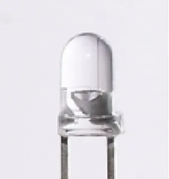
Figure sette.1 To tell which lead of the LED is the cathode look through its body: the thickest lead is the cathode (on the right in this picture). The picture has been taken fromWikipedia.
p i n M o d e ( pin , O U T P U T );
You can then set the state of this pin via software.
sette.2
Writing and reading digital pins
All pins can be used as digital pins, admitting only two values: HIGH and LOW. Some pin is available as analog pins (pins 3, 5, 6, 9, 10 and 11). When used as digital pins, output pins provide a signal of either 0 or 5 V, according to their state. To set a digital pin state you can use
d i g i t a l W r i t e ( pin , H I G H );
or
d i g i t a l W r i t e ( pin , LOW );
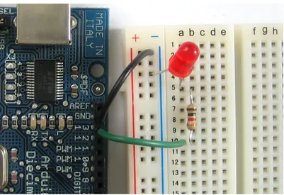
In the latter case you can find 0 V on the corresponding connector on theArduinoboard, while in the opposite case, you can find 5 V. With a digital pin, then, you can power on and off any device requiring a voltage of 5 V (or less, if you can divide the voltage by an appropriate circuit). For example, you can switch on and off an LED. Just connect the anode of the LED to the pin and its cathode to the ground (see Fig.sette.1). Upon execution of the statement digitalWrite(pin, HIGH); the LED switches on brightly. The brightness of the LED depends on the current flowing through it. Depending on the color, LED’s require a current of 15–20 mA to produce light. The current I flowing through a passive circuit element like the LED is given by the Ohm’s Law:
I =V