J. Anat. (2008) 213, pp183–193 doi: 10.1111/j.1469-7580.2008.00932.x
Blackwell Publishing Ltd
A model of the intracortical vascular system of long bones
and of its organization: an experimental study in rabbit
femur and tibia
Ugo E. Pazzaglia, Giovanni Bonaspetti, Federico Ranchetti and Pierfrancesco Bettinsoli
Clinica Ortopedica Università di Brescia, Spedali Civili di Brescia, ItalyAbstract
The vascular anatomy of the cortical bone and the canal system are highly correlated, and the former has an important bearing on shape and microscopic lamellar structure, as it is established in the progression of the remodelling process. The classical description of a longitudinal system of canals (Havers’) connected by the transversal Volkmann’s canals is the generally acknowledged model of the structural organization of the cortex. However, it is remarkably difficult to study the circulation inside the compact bone in detail owing to its hard, calcified matrix, and the methods thus far applied have represented either the bone morphology and the architecture of the canal system or the injected vessel network. In the present study, the intracortical vessel network was injected with black China ink and evidenced by transillumination of full-thickness, decalcified hemicortices. By making use of the depth of field of the microscope objective, the three-dimensional architecture of the network was highlighted and the morphometry of vessel size measurements and a classification of the network nodes according to the number of arms was made possible. These observations were integrated with data obtained by routine histology on decalcified sections relevant to the con-nections of the intracortical canal system with the outer environment, with regard to the direction of advancement of new canals and with regard to the mode of formation of the system nodes. The formation of the intracortical vessels network involved two processes: the incorporation of the periosteal network and osteonal remodelling, the latter occurring through the advancement of cutting cones followed by their own vascular loop and by concentric lamellar apposition. The two systems could be distinguished by the diameter of the vessels (the former were sig-nificantly larger) and by the network architecture (the former convoluted, and the latter longitudinally orientated and straight). Longitudinal vessels could form branches or create connections with the periosteal derived vessels that occasionally meet on the line of their advancement. They were observed entering from either inside the cortex from the metaphyses or from the endosteal surface of the marrow cavity. The combined observations from different methods of study documented a model of intracortical canal and vessel networks formed by two initially independent systems: one derived from the external, periosteal vessels, and one from metaphyseal and marrow vessels. Connections between the two were established with the advancing of cutting cones from the extremities of the diaphysis. Analysis of the system architecture and the modalities of its progressive organization suggested that the direction of advance-ment of a forming canal does not necessarily correspond to the final blood flow direction of its central vessel.
Key words bone architecture; bone remodelling; cortical bone; Haversian System.
Introduction
The growth in length of tubular bones occurs at the extremities where the metaphyseal growth plates are located. The cortex is formed at the lower level of the
metaphysis as a result of an intense remodelling activity of the more peripheral metaphyseal trabeculae, which reduces the outer perimeter of the metaphysis and aggregates the compact structure of the diaphyseal cylinder (Ham, 1957). As the structural organization of the compact, diaphyseal bone is driven by the progression of the vessels through unities known as ‘cutting cones’ (Shenk & Willenegger, 1964, 1967), the transition zone from the metaphysis to the diaphysis has a key role in understanding the patterns and modes of organization of the intracortical canal system and its related vessel network.
In the early phases of bone development the metaphyses are supplied by diaphyseal medullary arteries. However, in
Correspondence
Prof. Ugo E. Pazzaglia, Clinica Ortopedica Università di Brescia, Spedali Civili di Brescia, P. le Spedali Civili, 1 – 25123 Brescia, Italy. T: +390303995401; F: +39030397365;
Accepted for publication 8 April 2008 Article published online 8 July 2008
Intracortical vascular system of long bones, U. E. Pazzaglia et al. 184
subsequent phases metaphyseal vessels are acquired peripher-ally and at the end of growth the metaphyses are supplied by metaphyseal arteries alone (Brookes & Revell, 1998).
In a previous study, a reticular network pattern was observed in the part of the shaft near the metaphysis, while a prevailing longitudinal course of vessels was evident in the mid-shaft (Pazzaglia et al. 2007). The longitudinal polarization of calcified cartilage columns present in the upper and lower parts of the diaphysis and derived from the calcified cartilage intercolumnar septa of the growth plate were assumed as a possible, primary factor determining the direction of secondary osteonal remodelling inside the shaft (Pazzaglia et al. 2007).
It is remarkably difficult to investigate the circulation inside the compact bone thoroughly, owing to its hard, calcified matrix, and methods of study so far applied have represented either the bone morphology and the architecture of the canal system (Cohen & Harris, 1958; Smith, 1959; Vasciaveo & Batoli, 1961; Albu et al. 1973) or the injected vessel network (Brookes, 1961; Brookes & Lloyd, 1961; Hert & Hladíková, 1961; Trias & Fery, 1979; Marotti et al. 1980). SEM studies employing the cast corrosion technique have given a three-dimensional representation of the long bone vascular pattern with its main systems: the diaphyseal nutrient vessels, the outer periosteal network, the metaphyseal vessels and the low-pressure system of the bone marrow (Draenert & Draenert, 1980; Othani et al. 1982; Skawina et al. 1994). However, as it is difficult to perfuse the cortex with resin, it has, to date, been impossible to apply this method to a detailed study of the intracortical vessel network.
A modification to the method of studying the injected intracortical vascular network, which utilizes full-thickness, unstained hemicortex, made it possible to highlight the three-dimensional architecture of the network and to improve morphometry with regard to vessel size measure-ments and classification of the network nodes. Other information relevant to the connection of the intracortical vessel system to the outer environment, such as the direction of the advancement of new canals and the mode of formation of the system nodes, was obtained by routine histology on decalcified sections.
In the present study, aspects derived from histomorphology were integrated with the direct observation of the injected intracortical vessels in order to understand better the structural pattern of the system and the dynamics of its development. Better knowledge of the cortical bone structure and of the factors controlling its organization may also have an impact on our understanding of several clinical aspects such as the repair process of fractures, bone necrosis and osteoporosis.
Materials and methods
The study was carried out on the femurs and tibias of eight male New Zealand white rabbits (Stefano Morini, S. Polo d’Enza, Reggio Emilia, Italy), weighing between 3.0 and 3.5 kg and
approximately 8 months of age. The animals were housed in individual cages with food and water available ad libitum and kept in an animal house at a constant temperature of 22 °C with a 12-h light–dark cycle. All efforts were made to minimize animal suffering and the number of animals used. The experimental procedures were approved by the Italian Health Ministry.
To inject the vascular tree of the lower limbs all rabbits were anaesthetized with ketamine hydrochloride (Imagel) and xylazine (Rompum); the aorta and cava vein were exposed through a midline abdominal incision and a 1.5-mm catheter was inserted between the diaphragm and the origin of the renal arteries in a proximal to distal direction. The artery was then tightly fastened with two knots around the catheter and a slow continuous infusion of an heparinized saline solution was performed through the cannulated artery; the cava vein was then clamped with Klammer forceps and 300 mL of black China ink/water solution (60%) was injected with a hand syringe at a pressure of 150–200 mm of mercury until the lower limbs were completely perfused. High pressure in the extra-cortical, vascular tree was necessary to balance the difference of resistance to perfusion between extra-and intra-cortical vessel networks. However, no distension on vessels was produced in the intra-cortical sector. Just prior to China ink injection the rabbits were killed with an overdose of the anaesthetic.
The skin of the limbs was excised and both femurs and tibias were dissected from soft tissues, fixed in neutral formalin (10%) and decalcified in Osteosoft (Merk Sharp & Dome) at 37 °C for 2 months.
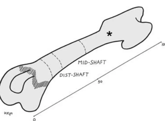
The left femurs and tibias were cut with a blade in a plane perpendicular to the major axis of the bone at mid-length. The proximal part of the femurs and the distal of the tibias were discarded, and the remaining part of the bone was further parted by cutting out the epiphyses and part of the metaphyses (with a section approximately 2 mm below the growth plate cartilage) (Fig. 1). Two cylinders 1.0 cm high were obtained from the extremities of these specimens, the first including part of the metaphysis and the adjoining diaphysis, marked as dist/prox-shaft, the second corresponding to the mid-diaphysis, marked as mid-shaft (Fig. 1).
The cylinders corresponding to dist/prox-shaft and mid-shaft were split in the mid-frontal plane into a ventral and dorsal half. The marrow and periosteal soft tissue were eliminated with a scalpel and the cylinders were cleared with a passage in 40% (w/ v) hydrogen peroxide solution in water for 24 h and stored in 2% formalin solution until microscopic observation. These specimens of the full-thickness cortex were then left to air dry for 3 min, and before losing their plasticity, they were pressed flat between two glass slides tightly secured at the extremities with adhesive tape. The flattened specimens had the shape of a quadrilateral approxi-mately 3 cm long and the other two sides measured 1.4 and 1.2 cm in the femur and 1.2 and 0.7 cm in the tibia. Part of the anterior tuberosity of the tibia was cut out to allow the flattening of the specimen between the two glass slides. The dorsal hemi-cortex was observed unstained in a bright field with an Olympus BX 51 microscope, with objectives Plan N 4× and uPlan FL N 10×. Utilizing the full depth of field of the latter objective and focusing on different planes of the thick cortex it was possible to make a multiplanar analysis of the spatial disposition of the vessels in a limited volume of the cortex. Digital images were captured with a Colorview IIIu video camera mounted on the microscope. The tissue specimens were then removed from the glass slides, stored again in the formalin solution and left available for further examination.
Intracortical vascular system of long bones, U. E. Pazzaglia et al. 185
The right distal femurs and proximal tibias were cut transversely following the same procedure as for the left side bones. These specimens were embedded in a block of paraffin and serial sections were cut with the microtome in the plane perpendicular to the long axis of the bone. They were stained with haematoxylin-eosin and the best (without technical artefacts) 20 slides representative of all the levels of the cylinder were selected for morphometry.
The remaining part of the diaphysis between the two cylinders was used to prepare longitudinal sections, which, together with transverse sections, were observed with an Olympus BX 51 microscope in a bright field, in polarized light and in phase contrast.
Morphometry
In each serial, transverse section of the right femur and tibia specimens corresponding to the dist/prox-shaft and the mid-shaft, the outer and inner perimeters and the cortical area were calculated utilizing the software Cell (Soft Imaging System GmbH, Munster, Germany). The number of vascular canals was counted and expressed as a function of the cortical area (n/mm). In the same way, the number of vascular canal openings on the inner and outer surface of the cortex was counted and expressed as a function of the inner and outer perimeter of the bone, respectively (n/mm). The values of these parameters for each rabbit femur and tibia were the mean of 20 serial slides. The dorsal hemi-shaft cortices corresponding to dist/prox-shaft and mid-shaft of the left femurs and tibias were used to emphasize the injected vessel network. By using the Plan N 4× objective (enlargement 40×) a general view of the pattern of vessels was obtained and by utilizing the full depth of field of the uPlan FL N 10× objective (enlargement 100×) it was possible to focus different planes of the same field and to capture the corresponding images, which were traced on transparent paper and used for a multiplanar analysis of the vessel network. Four images of the same field were used: the distance between each of them was about one-quarter of the depth of field of the objective (16 μm).
At the two extremities of each specimen two bands of 0.5 cm corresponding to distal/proximal-shaft (the wider side) and to mid-shaft (the narrower side) were selected. In these sectors a screen grid was superimposed to the slide, whose square-mesh net served as a mask to select ten microscopical fields at a 100× en-largement in such a way that they were regularly distributed on the whole surface of the sector examined. Two parameters in each field were assessed:
1 The diameter of the injected vessels measured with the software Cell, according to the following criteria:
a. individual vessels were identified as the tract between two adjoining bifurcations, between a bifurcation and the field margin or where the vessel became out of focus;
b. the largest diameter of the tract was measured and assigned to that vessel;
c. in mid-shaft two sub-groups of vessels were distinguished: those with a longitudinal direction (straight) and those orientated in all the other planes (convoluted).
2 The number of nodes of the vessel network present in each field (n/field); they were further distinguished according to the number of arms for each node (3 arms = bifurcation, 4 arms = trifurcation, 5 arms) and expressed as a percentage of the total number of nodes. These parameters were examined independently by two observers; inter-observer and intra-observer precision in the count of nodes and their type was expressed as the coefficient of variation (CV) of repeated measurements given on a percentage basis: the former was 11%, the latter 8 and 5%, respectively.
The mean value of the parameters assessed in each field was calculated. The values for each rabbit femur and tibia were the mean of ten fields for each bone.
Statistical analysis
On 40 serial, transverse sections for each femur and tibia the canal density between dist/prox-shaft and mid-shaft was compared with a paired Student’s t-test.
With regard to the surface opening densities the following sectors were compared via Student’s t-test:
1 endosteal versus periosteal surface of the mid-shaft,
2 endosteal mid-shaft versus endosteal dist/prox-shaft surface, and
3 endosteal mid-shaft versus endosteal + periosteal dist/prox-shaft surface.
In our multiplanar analysis of the vessel network the same test was used to compare the mean diameter of straight and convoluted vessels in ten random fields of the mid-shaft and ten of the dist/ prox-shaft of each femur and tibia. The means of eight femurs and tibias are reported in Tables 1 and 2.
The density of the network nodes was compared between dist/ prox-shaft and mid-shaft of the femurs and tibias by using the Student’s t-test, whereas the frequency analysis of each node type (expressed as a percentage of the total number of nodes) was performed with Pearson’s chi-square test.
Results
The injected vessel network in full-thickness, dorsal hemi-cortices at low magnification (40×) allowed the reticular pattern of the distal/proximal-shaft of the femurs and tibias to be distinguished from the longitudinal pattern of the mid-shaft of both bones (Fig. 2A,B). At an increased magnification the former showed no prevalence of loop size in any of the orthogonal planes, and the vessels had a more convoluted course and a lower number of network nodes than at a 40 × enlargement, since many intersections at the low-power observation proved to be optical artefacts resulting from the superimposition of different planes (Fig. 3). Straight, injected vessels with a diameter of about
Fig. 1 Scheme of the femur illustrating the section planes and the references for mid-shaft and distal-shaft levels (*proximal shaft).
Intracortical vascular system of long bones, U. E. Pazzaglia et al. 186
80–100 μm were occasionally observed inside the network of convoluted vessels (Fig. 4). These vessels represented the injected vascular loop of an advancing cutting cone.
The corresponding mid-shaft observations showed vessels with a straight and longitudinal direction while others, connecting the latter, showed a convoluted course similar to those of the dist/prox-shaft (Fig. 5).
The mean diameter of straight mid-shaft vessels was significantly greater than that of convoluted vessels at the same level of the diaphysis. When comparing mid-shaft convoluted vessels with those of the dist/prox-shaft, the mean diameter of the former was significantly higher in femurs but not in tibias.
Network node density was significantly higher in dist/ prox-shaft than in mid-shaft of both femurs and tibias. Another peculiarity was that in the mid-shafts all the observed intersections of the network had the format of nodes with three or four arms, while in dist/prox-shaft five arm nodes were observed as well (Table 1).
Standard histology revealed two different mechanisms of formation of the diaphyseal vascular network:
1 The first was the incorporation of the periosteal net-work of vessels lying on the outer surface of the bone (Fig. 6A) inside the layers of parallel lamellae laid down by the periosteum. One or, less frequently, two paired vessels of size between 10 and 20 μm have been observed to become incorporated in the same lacuna. These vessels have a thin wall formed by endothelial cells with no evidence of a concentric lamellar pattern (Fig. 6B). Their three-dimensional design reproduces the periosteal network from which they are derived (Fig. 6C). The latter is evenly distributed on the smooth surface of the diaphysis and the openings through which the vessels enter the cortex have a regular and rounded or oval perimeter and measure between 10 and 20 μm.
2 The second was the well-known osteonal pattern with the central vessel surrounded by its own system of con-centric lamellae. Among these, the completely structured
osteons (CSOs) had a central vascular space of about 10 μm and the actually structuring osteons (ASOs) showed a large range of sizes of 200 μm or more, decreasing progressively to the size of CSOs. The cutting cones had a polarized structure with osteoclasts located on the advancing front and vessels following at short distance behind. In trans-verse sections it was possible to observe an arteriole accompanied by one or more venules (Fig. 7A). The direc-tion of advancement and bifurcadirec-tion of tunnels appeared to be determined by the positioning of individual osteo-clasts with their ruffled border in contact with the bone matrix: if osteoclasts remain close together a single tunnel is dug, whereas if they diverge a bifurcation is formed (Fig. 7B).
An unusual aspect has been occasionally documented by the direct observation of the injected vessel network with the vessel turning in a circular motion and closing a loop at a short distance from a bifurcation (Fig. 7C). This figure could represent either the vascular loop of an advancing cutting cone or the vessel inside a canal that has reversed its longitudinal direction by 180°.
The intracortical canal system was evenly distributed within the mass of the cortex at different levels, but the density of the canals was significantly higher in mid-shaft of both femur and tibia (Table 2).
Connection of the intracortical canal system to the extra-cortical environment was investigated by surface observation of hemicortex specimens and by histology utilizing either mid-sagittal or transverse sections. Openings of approximately 10–20 μm and a sharp and regular edge were scattered on the periosteal surface of the shaft, corresponding to the points of entry of the periosteal vessels (Fig. 8A,B).
Other openings of larger size with a connective–vascular tissue in continuity with the marrow network were observed on the endosteal surface of the shaft (Fig. 8C). Occasionally, some of these were observed to be under-going formation with osteoclasts attacking the cortex with a
Fig. 2 (A) The reticular aspect of the vessel network in distal/prox-shaft of femur and tibia. (B) The longitudinal arrangement of vessels in the mid-shaft. Unstained hemicortex (bar = 500 μm).
Intracortical vascular system of long bones, U. E. Pazzaglia et al. 187
clear indication of an out to in direction of advancement of the new canal.
At the level of the dist/prox-shaft on both the periosteal and the endosteal surfaces, elongated and highly irregular openings (clefts), through which the metaphyseal vessels entered the cortex, were present.
Comparing the density of surface openings there were no significant differences between the periosteal and
endosteal surfaces at the level of the mid-shaft, nor were there differences between the endosteal surface of the mid-shaft and that of the dist/prox-shaft. The total density of openings in dist/prox-shaft (outer + inner surfaces) was significantly higher than that of the mid-shaft endosteal surface (Table 2).
Indications of the original direction of advancement of CSOs was drawn by the observation of blind ends and by the lamellar organization around bifurcations: the direction of advancement was from the single canal towards its branches, given that, after parting, they maintained a common, concentric lamellar system for a certain distance, which then developed into two independent osteons. There were osteons that had either proximal or distal advancement directions.
In all diaphyses the most proximal and distal part of the cortical bone, even at a considerable distance from the growth plate, included longitudinal columns of calcified cartilage. The osteons ran parallel to these columns and in transverse sections they were close to each other (Fig. 9A,B).
Discussion
The study of bone intracortical circulation is difficult for several reasons. The first reason is technical, as the vessel network is incorporated inside the hard mass of cortical bone so that decalcification is required in order to apply standard histological methods. However, this also limits the injection procedures as only low-viscosity solutions can perfuse the network of the thin, cortical vessels. The second reason is that the spatial organization of the system is gradually established during the course of bone growth, and even when the final shape and size are reached it is continuously modified by the remodelling process. Therefore,
Fig. 3 Multiplanar analysis of the dist/prox-shaft network of the femur based on the same area focused on different planes. The distance between the two images displayed is about two-thirds of the depth of field of the objective (about 12 μm). Unstained hemicortex (bar = 200 μm).
Fig. 4 An actually structuring osteon advancing among the periosteal-derived vessel network of the femur distal-shaft; connection between the two systems is established when the cutting cone of the straight canal intersects a convoluted canal. Unstained hemicortex (bar = 100 μm).
Intracortical vascular system of long bones, U. E. Pazzaglia et al. 188
Fig. 5 Multiplanar analysis of the mid-shaft network of the femur based on the same area focused on different planes. The distance between the two images displayed is about two-thirds of the depth of field of the objective. Unstained hemicortex (bar = 200 μm).
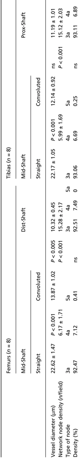
Table 1
Mean diameter of straight and convoluted vessels of mid-shaft and distal/proximal-shaft. Mean frequency of network nodes and pe
rcentage distribution of each type of node
Femurs ( n = 8) Tibias ( n = 8) Mid-Shaft Dist-Shaft Mid-Shaft Prox-Shaft Straight Convoluted Straight Convoluted Vessel diameter ( μ m) 22.62 ± 1.47 P < 0.001 13.87 ± 1.02 P < 0.005 10.32 ± 0.45 22.17 ± 1.05 P < 0.001 12.14 ± 0.92 ns 11.19 ± 1.01
Network node density (
n /field) 6.17 ± 1.71 P < 0.001 15.28 ± 2.17 5.99 ± 1.69 P < 0.001 15.12 ± 2.03 Type of node 3a 4a 5a 3a 4a 5a 3a 4a 5a 3a 4a 5a Density (%) 92.47 7.12 0.41 ns 92.51 7.49 0 93.06 6.69 0.25 ns 93.11 6.89 0
Intracortical vascular system of long bones, U. E. Pazzaglia et al. 189
Fig. 6 (A) Incorporation of periosteal vessels lying on the outer surface of the diaphysis by peripheral lamellar apposition. Haematoxylin-eosin stain (bar = 200 μm). (B) Same field in polarized light, showing the absence of a system of concentric lamellae around the already incorporated vessel (arrow). Haematoxylin-eosin stain (bar = 200 μm). (C) Panoramic view of the outer periosteal network of vessels on the antero-medial surface of the tibia (*). The intracortical network is derived from this surface network. Unstained shaft (1.5×).
Fig. 7 (A) Transverse section of an actually structuring osteon forming a tunnel of about 250 mm; it contains a central arteriole and two capillaries with a thin endothelial wall. Osteoblasts are present in the lower zone of the canal surface (between arrows), but no complete concentric lamellar system is yet evident. Haematoxylin-eosin stain (bar = 50 μm). (B) Longitudinal section of the cortex showing an actually structuring osteon with osteoclasts at the head of the cutting cone diverging to form a bifurcation. Haematoxylin-eosin stain (bar = 50 μm). (C) Vessel turning in a circle and closing a loop at short distance from a bifurcation (arrow). Unstained hemicortex (bar = 200 μm).
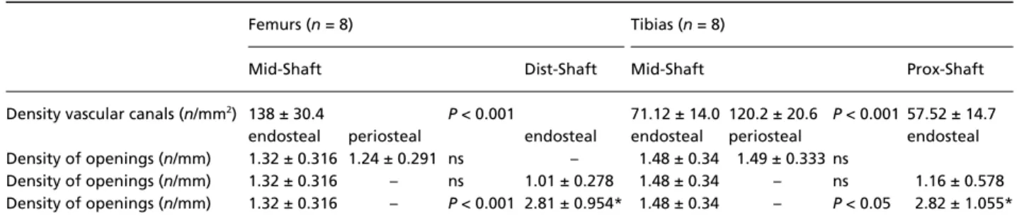
Table 2 Mean density of intracortical canals and outer environment connections at different levels of the shaft
Femurs (n = 8) Tibias (n = 8)
Mid-Shaft Dist-Shaft Mid-Shaft Prox-Shaft
Density vascular canals (n/mm2) 138 ± 30.4 P < 0.001 71.12 ± 14.0 120.2 ± 20.6 P < 0.001 57.52 ± 14.7
endosteal periosteal endosteal endosteal periosteal endosteal Density of openings (n/mm) 1.32 ± 0.316 1.24 ± 0.291 ns – 1.48 ± 0.34 1.49 ± 0.333 ns
Density of openings (n/mm) 1.32 ± 0.316 – ns 1.01 ± 0.278 1.48 ± 0.34 – ns 1.16 ± 0.578 Density of openings (n/mm) 1.32 ± 0.316 – P < 0.001 2.81 ± 0.954* 1.48 ± 0.34 – P < 0.05 2.82 ± 1.055* *In the columns of dist/prox-shaft the boxes marked by asterisks correspond to the sum of endosteal and periosteal openings.
Fig. 8 (A) Openings on the periosteal surface corresponding to the points of entry of the periosteal vessels. Unstained hemicortex (bar = 100 μm). (B) Detail of an opening with the injected vessel inside. Unstained hemicortex (bar = 50 μm). (C) Transverse section of the mid-shaft documenting the vascular connection between the intracortical network and marrow on the endosteal surface (arrowheads). Haematoxylin-eosin stain (bar = 200 μm).
Intracortical vascular system of long bones, U. E. Pazzaglia et al. 190
the dynamics of these processes must be considered even for a description of the morphology of the system.
In the present study a single age group of 8-month-old rabbits was used. As animals of this age are still growing, and the primary structural organization of the cortical bone occurs between the metaphysis and the shaft, it was possible to obtain a morphological representation of the develop-ment of the canal and vessel network systems in long bones that is valid for the entire period of growth, even without the experimental application of different age groups.
An improved resolution and three-dimensional imaging of the long bone vascular system was obtained by combining corrosion casting with scanning electron microscopy (Draenert & Draenert, 1980; Othani et al. 1982; Draenert, 1983). However, observations by these authors were limited to the main nutrient vessels passing through the cortex and the extra-cortical systems as it has not yet been possible to inject the fine intracortical network with a resin satisfactorily. Only Skawina et al. (1994) showed corrosion casts of the connections between the marrow sinusoids and the cortical vessels. However, the latter were limited to the surface layer.
It has also been documented that three-dimensional morphometry applied to microvascular corrosion castings allows more accurate dimensional and angular measurements than two-dimensional images (Minnich & Lametschwandtner, 2006). However, as with the studies above, this type of study has not yet found an application to intracortical vessels owing to problems with resin injection and perfusion of the fine capillary.
To highlight the architecture of the vessel system, combined observations from the application of different light microscopy methods of study provided a more detailed description of the intracortical system and of its mode of organization.
The black China ink injection method, as applied here, gave a sufficiently good view of the vessel network of the cortical bone and emphasized the reticular pattern of the most proximal and distal parts of the diaphysis in comparison
with the prevailing longitudinal arrangement of the vessels in the mid-shaft (Pazzaglia et al. 2007). However, repre-sentation of the vessel network on a two-dimensional plane is influenced by a projectional bias. This is due to the fact that many crossings of vessels lying on different planes appear as network nodes, while in three-dimensional space they do not correspond to a real confluence of vessels. The same problem is present with all the methods of study that utilize injected contrast dyes and thick sections or full bones (Brookes & Revell, 1998; Minnich et al. 1999; Minnich & Lametschwandtner, 2006).
Using the full depth of field of the microscope objective on a full-thickness hemicortex at an enlargement of 100× it was possible to increase the definition of the injected vessels and to improve two-dimensional measurement of vessel size (but not with the accuracy of three-dimensional morphometry in scanning electron microscopy (Minnich et al. 1999). More importantly, in a light microscopy study, it was possible to discriminate true network nodes from optical artefacts, which allowed a multiplanar representation of the network in a sufficiently large field of observation. Its application also made it possible to differentiate con-voluted vessels of the dist/prox-shaft and mid-shaft from straight vessels (not only on the basis of their shape, but also size), and to classify the types of network nodes in relation to the number of arms.
Histology further supported the presence of two types of vessels and documented the origin of the smaller, convoluted vessels from the external periosteal network (Morgan, 1959). They were progressively incorporated inside the cortex during perimetric growth of the diaphysis and maintained the original random arrangement. As the process of incorporation is slow, standard histological slides gave a static view of periosteal vessels at different depth levels from the bone surface. In experimental con-ditions where periosteal apposition was enhanced (i.e. medullary canal reaming or cementing) it was possible to document via vessel injection and tetracycline labelling
Fig. 9 (A) In longitudinal section osteons run parallel to calcified cartilage columns of distal/proximal shaft (asterisks). Haematoxylin-eosin stain (bar = 100 μm). (B) In transverse section the structured osteon (asterisk) has advanced along the line of a calcified cartilage column, whose remnants are evident at the periphery of the osteon (arrowheads). Haematoxylin-eosin stain (bar = 100 μm).
Intracortical vascular system of long bones, U. E. Pazzaglia et al. 191
techniques the dynamics of the periosteal network incorpora-tion (Hammersen & Seidemann, 1964). The present study provides evidence that around these vessels there is no concentric lamellar organization and this observation supports the mechanism of vessel incorporation described earlier.
Straight vessels have a different origin: their structure, direction and the surrounding lamellar organization follows the advancing cutting cones and represents, with regard to the mode of formation, a vascular system completely independent from the periosteal lamellae.
However, connections between the two systems are established early: during their advancement the cutting cones destroy a certain volume of bone matrix, which includes endosteal- and periosteal-derived lamellae as well as, during the progress of remodelling, older osteons. The perio-steally derived canals network, which find themselves on the trajectory of the advancing cutting cone, open in the tunnel of the new osteon and a connection between the periosteal convoluted vessel and the central vascular axis of the forming osteon is formed (Fig. 10A). According to this model the convoluted vessels of the mid-shaft connecting straight central vessels of the osteonal system (Volk-mann’s) are derived from the periosteal vascular system. The intracortical network of convoluted vessels has a random architecture which reproduces the design of several layers of the periosteal surface network progressively
incorporated inside the cortex. By contrast, the osteonal vessel system shows a well-defined polarization with vessels running along the major axis of the bone. In this context it may be relevant to discuss where these vessels enter the cortical bone and the factors determining their direction.
The total density of network nodes and the frequency distribution of node types did not show any significant difference between dist/prox-shaft and mid-shaft. This result is not in contrast with the hypothesized mechanism of connection formation between the periosteal-derived and the osteonal system in the course of remodelling. Indeed, if a cutting cone is supposed to destroy the canals and the relative nodes of the periosteal-derived system
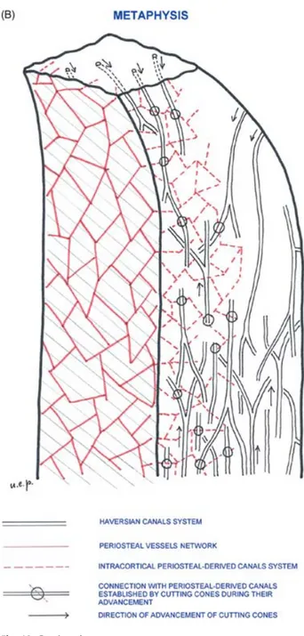
Fig. 10 (A) Scheme illustrating the modality of connection between the periosteal-derived canal system and the Haversian system. Four levels of the periosteal-derived canal network have been represented with a square-mesh net of different colours and projected on the horizontal plane. It has been assumed that the cutting cones advance along a direction perpendicular to this plane. There are three possible intersections: (A) the cutting cone does not intersect any periosteal derived canal at any level; (B) it intersects a canal at one level; and (C) it intersects a canal at two levels. The probability of intersection in this model depends on the relative position of the advancing cutting cone and the periosteal-derived canal network, but also on the sizes of the net meshes and the density of cutting cones. (B) Three-dimensional organization of the intracortical canal system in the process of growth and development of a long bone.
Intracortical vascular system of long bones, U. E. Pazzaglia et al. 192
which lies on its advancement front, then new connections (nodes) would be established by the vessels of the periosteal-derived system, which would then open inside the new tunnel.
The regular openings observed on the periosteal surface corresponded to the orifices through which the intracortical, periosteal-derived vessels are connected with the surface network.
The cutting cone vessels entered the cortex through elongated and more irregular openings (clefts) scattered on the endosteal surface of the medullary canal up to the sub-metaphyseal part of the diaphysis and, at this level, also on the outer periphery of the metaphysis. No open-ings of this type were observed on the periosteal surface of the diaphysis. The comparison between the density of surface vascular openings at different levels of the shaft revealed that the main source of straight intracortical vessels (Havers’ system) were the extremities of the diaphysis, where the cortex is formed by compaction of metaphyseal trabeculae and apposition of surface lamellae. These findings are in agreement with the observations of micro-angiographic studies of long bone vascular organization, which describe a large number of metaphyseal arteries, known as Hunter’s vascular circle, entering the bone at this level (Hammersen, 1981; Pazzaglia et al. 1997).
Vessels entering the cortex from the marrow cavity at the level of the mid-shaft were supposed to have an out to in direction, as suggested by the observation of osteoclasts initiating a new canal on the endosteal surface. However, it cannot be excluded that a cutting cone from the inner cortex could occasionally open outside the cortex in the medullary canal.
Bifurcations of the osteonal system vessels were frequently observed and analysis of the lamellar organization provided evidence of the direction of the cutting cone advancement, as well as the presence of blind ends (Rogers & Gladstone, 1950; Cohen & Harris, 1958; Shenk & Willenegger, 1967). Given that in the same diaphysis bifurcations and blind ends were observed to be orientated either proximally or distally it is possible to suggest that the polarization of new osteons is correlated with their point of origin: those starting from the proximal metaphysis are distally directed while those from the distal metaphysis have the opposite direction. This pattern of organization could explain the higher canal density of the mid-shaft compared with the distal or proximal shaft.
Canal openings of the endosteal mid-shaft may be old metaphyseal entrance points of vessels which came down towards the mid-diaphysis following length growth of the bone, or they may represent new canals starting from the marrow vessels. The latter can be proximally or distally directed or form a T bifurcation with branches in both directions.
The line of advancement of the forming osteons was determined by the osteoclast at the head of the cutting
cone, and it is possible to explain their straight course via the presence of the columns of calcified cartilage in the dist/prox shaft or in the central part of the diaphysis by the columnar arrangement of the interosteonic breccia (Pazzaglia et al. 2007). This model of the intracortical canal network is shown schematically in Fig. 10B and is in agreement with the morphology and the branching pat-tern obtained by micro-CT three-dimensional reconstruc-tions of the canals system in cortical bone (Cooper et al. 2003, 2006).
The intracortical vessel network was normally found to reproduce the design of the canal system, even if it cannot be excluded that some canals are free of vessels, as sealed osteons were occasionally observed.
It remains uncertain if the blood flow maintains the direction that characterized the advancement of the cutting cone. The morphological methods used here are not applicable to investigate blood flow haemodynamics. However, there was a clear difference between the ASOs with a cutting cone at the head and CSOs. The former were large enough to contain a vascular loop with an afferent vessel (an arteriole) and one or more vessels with a thin endothelial wall, suggesting an efferent blood flow through the latter. CSOs, which have a much smaller central canal, are almost completely filled by an endothelial-walled vessel with only a thin gap between the vessel wall and the innermost lamella. In this case, it is impossible to comment on the flow direction inside the vessel.
These observations support the concept that the vessel system is modulated in the course of osteon formation and that when the latter has completed its structure the number of vessels inside is usually reduced to one. At this point, the flow direction inside the specific osteon depends on the connections of the network and the pressure gradient between afferent and efferent vessels. Owing to the fact that in CSOs no vessels with a muscle tunica are present, the pressure gradient is determined by the arterioles afferent to the cortex at different levels (metaphyseal, periosteal and medullary branches of the principal nutrient artery) and by the negative pressure of the drainage pathways.
Knowledge of the normal microcirculation of the dia-physeal cortex and its response to fracture (Rhinelander, 1968) have significantly influenced the mode of treatment of the latter and the design of orthopaedic devices. Our observations here highlight the pattern of intracortical organization and document the key role of the vessel system. Other pathologies, such as bone necrosis and osteoporosis, could benefit from the increased knowledge regarding cortical bone organization.
References
Albu I, Georgia R, Stoica E, Giurgiu T, Pop V (1973) Le sistème des canaux de la couche compacte diaphysaire des os longs chez l’homme. Acta Anat84, 43 – 51.
Intracortical vascular system of long bones, U. E. Pazzaglia et al. 193
Brookes M (1961) A new concept of capillary circulation in bone
cortex. Lancet20, 1078 –1081.
Brookes M, Lloyd EG (1961) Marrow vascularization and
estrogen-induced endosteal bone formation in mice. J Anat95, 220 – 228.
Brookes M, Revell WJ (1998) Blood Supply of Bone. Scientific
Aspects. London: Springer Verlag.
Cohen J, Harris WH (1958) The three-dimensional anatomy of
haversian systems. J Bone Joint Surg (Am)40A, 419 – 434.
Cooper DML, Turinsky AL, Sensen CW, Hallgrimson B (2003)
Quantitative 3D analysis of the canal network in cortical bone by micro-computed tomography. Anat Rec (part B)274B, 169 – 179.
Cooper DML, Thomas CDL, Clement JG, Hallgrimsson B (2006)
Three-dimensional microcomputer tomography imaging of basic multicellular unit-related resorption spaces in human cortical bone. Anat Rec288A, 806 – 816.
Draenert K (1983) Studying bone regeneration with the scanning electron miscroscope. Scan Electron Microsc P + 1, 247–254. Draenert K, Draenert Y (1980) The vascular system of bone marrow.
Scan Electron Microsc 4, 113 –22.
Ham AW (1957) Histology. Philadelphia: J.B. Lippincott Co. Hammersen F (1981) Anordnung und Musterbildung der terminalen
Strombahnen der Periostes. Morphologie und Funktion der
Hüfte, Histo-Morph Bewegungsapp 1, 53–63.
Hammersen F, Seidemann I (1964) Ein Beitrag zur Angioarchitektonik der Knochenhaut. Arch Orthopäd Unfall-Chirur 56, 617–633. Hert J, Hladíková J (1961) Die Gefässversorgung des Haversschen
Knochens. Acta Anat 45, 344 –361.
Marotti G, Zambonin Zallone A (1980) Changes in the vascular network during the formation of haversian systems. Acta Anat 106, 84 –100.
Minnich B, Lametschwandtner A (2006) Lengths measurements in microvascular corrosion castings: two-dimensional versus three-dimensional morphometry. Scanning 22, 173–177.
Minnich B, Leeb H, Bernroider EWN, Lametschwandtner A (1999) Three-dimensional morphometry in scanning electron microscopy: a technique for accurate dimensional and angular measurements of microstructures. J Microsc 195, 23–33.
Morgan JD (1959) Blood supply of growing rabbit’s tibia. J Bone Joint Surg 41B, 185–203.
Othani O, Gannon B, Ohtsuka A, Murakami T (1982) The micro-vasculature of bone and especially of bone marrow as studies by scanning electron microscopy of vascular casts. A review. Scan
Electron Microsc I, 427–34.
Pazzaglia UE, Andrini L, Di Nucci A (1997) The reaction to nailing or cementing of the femur in rats. A microangiographic and fluorescence study. Int Orthop 21, 267–273.
Pazzaglia UE, Bonaspetti G, Rodella LF, Ranchetti F, Azzola F (2007) Design, morphometry and development of the secondary osteonal system in the femoral shaft of the rabbit. J Anat 211, 303 –312.
Rhinelander FW (1968) The normal microcirculation of diaphyseal cortex and its response to fracture. J Bone Joint Surg 50A, 784 –800. Rogers WH, Gladstone H (1950) Vascular foramina and arterial supply of the distal end of the femur. J Bone Joint Surg 32A, 867–874.
Shenk R, Willenegger H (1964) Zur Histologie der primären Knochenheilung. Langenbecks Arch Chir 308, 440 – 452. Shenk R, Willenegger H (1967) Morphological findings in primary
fracture healing. Symp Biol Hung 7, 75– 86.
Skawina A, Litwin JA, Gorczyca J, Miodonski AJ (1994) The vascular system of human fetal long bones: a scanning electron microscope study of corrosion casts. J Anat 185, 369 –376.
Smith JW (1959) Collagen fibre patterns in mammalian bone. J Anat, 94, 329 –344.
Trias A, Fery A (1979) Cortical circulation of long bones. J Bone Joint Surg 61-A, 1052–1059.
Vasciaveo F, Batoli E (1961) Vascular channels and resorption cavities in tha long bone cortex of the bovine bone. Acta Anat 47, 1–2.