CAMPUS DI CESENA
INGEGNERIA DELL’ENERGIA ELETTRICA E DELL’INFORMAZIONE
“GUGLIELMO MARCONI”
CORSO DI LAUREA MAGISTRALE IN INGEGNERIA BIOMEDICA
FINITE ELEMENT STUDY OF
FRACTURED MANDIBLE IN HUMAN
AND SHEEP
Tesi in:
Meccanica dei Tessuti Biologici LM
Relatore
Prof. Ing. Luca Cristofolini
Correlatori
Presentata da
Vincenzo Orassi
Prof. Dr. Sara Checa Esteban
Dr. Med. Dent. Carsten Rendenbach
III Sessione
Contents
Sommario ... 4 Abstract ... 6 INTRODUCTION ... 8 1.1 Clinical Motivation ... 8 1.2 Background ... 101.2.1 Anatomy of human mandible ... 10
1.2.2 Human masticatory system ... 11
1.2.3 Anatomy of sheep mandible ... 16
1.2.4 Sheep masticatory system ... 16
1.2.5 Etiopathogenesis of mandibular trauma ... 18
1.2.6 Fracture healing ... 19
1.2.7 Mandibular fracture management ... 20
1.2.8 Plating Systems: Nonlocking versus Locking Plates ... 22
1.2.9 Limitations of current treatments ... 24
1.2.10 Magnesium in bone healing ... 25
1.3 State of art ... 26
1.4 Aim ... 29
MATERIALS AND METHODS ... 30
2.1 Mandibular Geometry ... 30
2.1.1 Segmentation ... 31
2.1.2 Meshing process ... 32
2.2 Finite element model of human and sheep healthy mandible ... 34
2.2.1 Material properties ... 34
2
2.2.3 Loads ... 36
2.3 Finite element model of human ad sheep plate-fixated fractured mandible . 41 2.3.1 Modeling fractured mandible ... 41
2.3.2 Modeling Plate Fixation ... 42
2.3.3 Material properties in the fractured mandible ... 44
2.3.4 Meshing process ... 44
2.3.4 Constrains ... 45
RESULTS ... 46
3.1 Mechanical behaviour of human and sheep mandible under clenching loading ... 47
3.2 Fractured sheep mandible stabilized with miniplates ... 50
3.2.1 Strain Distribution within the fracture gap ... 50
3.2.2 Von Mises stress distribution in the fixations systems ... 52
3.3 Fractured human mandible stabilized with miniplates ... 55
3.3.1 Strain Distribution within the fracture gap ... 55
3.3.2 Von Mises stress distribution in the fixations systems ... 56
DISCUSSION ... 60
4
Sommario
Introduzione. L'osteosintesi è uno dei soggetti più discussi e studiati nella letteratura
ortopedica. Le fratture mandibolari sono una delle principali cause di lesione facciale e il loro impatto sulla vita del paziente può portare a conseguenze gravi, compromettendo la masticazione, l’uso della parola e l'estetica facciale. Gli attuali trattamenti per fratture semplici della mandibola includono l'uso di dispositive di tipo load-sharing, quali mini-placche e viti in titanio, che hanno il ruolo di fissare le estremità della frattura e ripristinare la continuità facciale. I sistemi di fissaggio mirano in definitiva a generare delle deformazioni meccaniche ottimali all'interno della regione della frattura, con lo scopo di promuovere il processo di guarigione dell'osso. Tuttavia, non vi è una chiara comprensione dell'influenza della stabilità di tali sistemi sulla biomeccanica delle fratture mandibolari stabilizzate, in particolare quando si utilizzano biomateriali diversi dal titanio. Lo scopo di questo studio è quello di indagare la risposta biomeccanica della mandibola fratturata usando delle tradizionali mini-placche in titanio e sistemi di fissaggio alternativi realizzati in lega di magnesio. In prospettiva di future valutazioni precliniche di questi nuovi dispositivi, sono studiati sia modelli mandibolari umani che ovini.
Materiali e metodi. Modelli 3D agli elementi finiti (FE) di mandibola umana e di
pecora sono stati ricostruiti a partire da scansioni realizzate mediante tomografia computerizzata a fascio conico (CBCT). Sono state riprodotte anche le geometrie 3D CAD di viti 2.0 e mini-placche a 4 fori 2.0 (con spessori di 1 mm e 1.5 mm), sulla base di modelli attualmente disponibili in commercio. Per lo studio in condizioni patologiche, sono state simulate delle fratture semplici, in entrambi i modelli, nella regione del corpo mandibolare e per il fissaggio sono state applicate due mini-placche parallele. Quindi, diverse proprietà meccaniche sono state
5
assegnate all'osso corticale e trabecolare, alla regione della frattura ed ai dispositivi di fissaggio (lega di titanio Ti-6Al-4V versus lega di magnesio WE43). Infine, sono stati applicati carichi e condizioni al contorno per simulare una specifica situazione di serramento dentale.
Risultati. Le deformazioni meccaniche all'interno della mandibola sana sono
risultate simili nella pecora e nell'uomo: è stata determinata una risposta approssimativamente simmetrica e sono state riscontrate deformazioni più elevate nelle regioni del collo condilare. In entrambi i modelli, una frattura patologica ha portato ad un aumento delle deformazioni meccaniche all'interno della regione di guarigione a causa delle ridotte proprietà meccaniche. Inoltre, nella mandibola ovina, le deformazioni hanno subito una diminuzione nelle fratture fissate con placche più spesse, mentre si è osservato un loro aumento nella mandibola umana. Per quanto concerne mini-placche e viti, le tensioni von Mises più elevate sono state riscontrate nelle regioni centrali delle mini-placche, in corrispondenza della linea di frattura, e nella testa delle viti. È stato generalmente osservato una diminuzione delle tensioni von Mises al ridurre della rigidezza del materiale oppure all’aumentare dello spessore delle mini-placche.
Discussione. I modelli FE sviluppati in questo studio sono stati utilizzati per studiare
l'effetto dei dispositivi di fissaggio nel trattamento di fratture mandibolari semplici. Abbiamo determinato che i livelli dei segnali meccanici sotto i quali la guarigione ossea ha luogo nella mandibola sono molto più bassi di quelli riscontrati nelle ossa lunghe. Inoltre, è stato dimostrato che le mini-placche in lega di magnesio forniscono sufficiente stabilità meccanica iniziale per il trattamento di fratture semplici. Gli studi futuri si concentreranno sulla simulazione di nuovi modelli di frattura e di grandi difetti mandibolari, inoltre, saranno valutate strategie alternative per superare i limiti degli attuali trattamenti mandibolari.
Abstract
Introduction. Osteosynthesis is one of the most discussed and investigated subjects
in the orthopaedic literature. Mandible fractures are reported as one of the main causes of facial injury and their impact on patient life may bring serious consequences, compromising masticatory function, speech and facial aesthetics. Current treatments for mandibular simple fractures include the use of load-sharing devices such as titanium miniplates and screws, which have the role of fixing the fracture ends and restore the facial continuity. Fixation systems ultimately aim to generate the optimum mechanical strains within the fracture region, which will promote the bone healing process. However, there is not a clear understanding of the influence of fixation stability on the biomechanics of stabilized mandibular fractures, particularly when using biomaterials different from titanium. The aim of this study is to investigate the biomechanical response of fractured mandible using traditional titanium miniplates and alternative fixation systems made of magnesium alloys. With a view on future preclinical evaluation of these new devices, both human and sheep models are investigated.
Materials and Methods. 3D finite element (FE) models of human and sheep
mandible were reconstructed from Cone-Beam Computer Tomography (CBCT) scans. 3D CAD geometries of screws 2.0 and 4-hole miniplates 2.0 (with 1 mm and 1.5 mm thickness), were also reproduced according to one of the commercially available designs. In the pathological condition, a fracture gap was simulated in both models in the body region and fixed with two parallel miniplates. Then, different material properties were assigned to the cortical and trabecular bone, fracture gap and to the fixation devices (Ti-6Al-4V titanium alloy versus WE43 magnesium alloy). Finally, loads and boundary conditions were applied to simulate a clenching task.
7
Results. Mechanical strains within the healthy mandible were similar in sheep and
human: an approximately symmetrical response was determined and highest strains were predicted in the condylar neck regions. In both models, a pathological fracture led to an increase of mechanical strains within the healing region due to reduced mechanical properties. Moreover, in the sheep mandible, strains decreased with thicker plates, while an increase was observed in the human mandible. Regarding miniplates and screws, highest von Mises stresses were found in the middle regions of the miniplates spanning the fracture gap and in the screws head. It was generally observed a decrease of von Mises stresses when reducing material stiffness or increasing miniplates thickness.
Discussion. The FE models developed in this study were used to investigate the
effect of fixation devices in the treatment of simple mandibular fractures. With this project, we determined that the levels of mechanical signals under which bone healing takes place in the mandible are much lower than those in long bones. In addition, magnesium alloy miniplates were proved to give enough initial mechanical stability for the treatment of simple fractures. Future studies will focus on the simulation of new fracture patterns and large mandibular defects and, in this latter case, on the evaluation of alternative strategies to overcome the limitations of current mandibular treatments.
8
1.
INTRODUCTION
1.1 Clinical Motivation
The management of fractures to the maxillofacial complex remains a challenge for oral and maxillofacial surgeons. Particularly, mandible fractures are a common form of facial injury and have been reported as accounting for 36% to 59% of all maxillofacial fractures [1] [2].
A fracture of mandibular bone compromises the masticatory function, speech and facial aesthetics. Therefore, an early mobilization in mandibular reconstruction aims to restore facial form and function, repairing mandibular continuity and muscle attachments. AO internal fixation systems and miniplates osteosynthesis are the current standard for mandibular fractures treatment. The ideal plate-screw system must provide enough strength to the functional loads inside the mandible, at the same time promoting fracture healing.
Titanium plates have been used for more than two decades for internal rigid fixation of mandible fractures. One of the major disputes concerns the need of a second surgery to remove asymptomatic plates. In fact, a titanium plate is intended to assist the bone healing process and it becomes a nonfunctional implant once the latter is completed. Although there is no actual evidence of a harmful effect and it is not possible to state with certainty that it has no consequences on the tissues and it is often preferable to leave it in situ to avoid a second surgery. However, the presence of a plate may cause a stress-shielding effect on the underlying bone [3]. In addition, it generates artifact during CT and MRI scan that may compromise the image quality, creating difficulties in interpretation with serious consequences especially in patients with cancer.
9
Therefore, new fixation systems using biodegradable biomaterials have been investigated as an alternative to titanium. Surely one of the most promising is magnesium, which is resorbable, it has osteogenic properties, it is less stiff than titanium and it does not interfere with diagnostic imaging.
So far, the influence of fixation stability on the biomechanics of stabilized mandibular fractures remains partially unknown, especially in case of biomaterials different from titanium. In the past, the effect of magnesium fixation on mandible fractures has been mainly investigated on smaller animals, like mice or rats. However, there is a need for a large animal model to facilitate preclinical evaluation of surgical and mechanical treatments being sheep a valid candidate for many reasons [4]:
• the size of the mandible is comparable to humans, making them suited to surgical procedures;
• they are genetically closer to human than rodents and mice;
• they usually receive an ethical approval easier than domestic pets and non-human primates;
• they require a relatively low economical effort.
Against this background, in this study sheep has been chosen as a large animal model in order to investigate the mechanical behavior of new magnesium fixation systems and to compare the achieved results to that obtained in the computational model of human mandible.
10
1.2 Background
1.2.1 Anatomy of human mandible
The mandible, or lower jaw, is the largest and strongest bone in human face [5]. It consists of two different regions (Figure 1.1) [6]: 1) the body, a curved, U-shaped horizontal portion; 2) the ramus, perpendicular to the body, which units with it at the gonial angle. Moreover, two processes extend in the upper part of the ramus. The coronoid process is a thin, triangular eminence, and the condylar process, thicker than the coronoid, which consists of mandibular condyle and the neck.
The condyle articulates to the temporal bone of the skull through the temporomandibular joint (TMJ). The articular surfaces are highly incongruent, therefore this allows for a large amount of motion, however sacrificing stability of the joint.
The mechanical function of mandibular bone is determined by its structure and material properties. In fact, bone is a dynamic tissue, which constantly undergoes resorption and remodeling processes [7], adapting its microstructure to loads and deformation stimuli. Mandible, like most human bones, is divided into an external
11
cortical bone and an internal cancellous tissue. The geometric distribution of these tissues depends on the mechanical stresses inside the structure. In fact, due to the presence of teeth, trabecular bone thickens forming the alveolar process, which supports tooth sockets. Moreover, the outer cortex of the body has an average thickness of 3.3 mm [8], which offers a good anchorage for screws application. Under the third molar, cortical bone is thicker at the lower border, behind the third molar it is stronger at the upper border (Figure 1.2). Such distribution translates into regional variations of elastic properties for human dentate mandible [9].
1.2.2 Human masticatory system
The human masticatory system is an example of kinematically and mechanically indeterminate system [10]. Mandibular movements are guided by the TMJ articular surfaces (Figure 1.3), one located on the temporal bone of the skull and the other one on the ovoid condylar head of the mandible. They are separated by a cartilaginous articular disk, which reduces the joint incongruity and increases stability by enlarging the contact area. Due to their construction, the two joints allow movements with six degrees of freedom.
12
In fact, masticatory muscles may have different activation patterns, which make the system redundant since they are able to influence more than one degree of freedom [11]. One of the reasons for this is that they must adapt constantly to different texture of food between the teeth.
The main muscles of mastication include masseter, temporalis, medial pterygoid, lateral pterygoid, digastricus, geniohyoid and mylohyoid (Figure 1.4) [12] [13]. From the anatomical point of view, they can be divided into mouth opening and mouth closing muscle groups. Digastricus, geniohyoid and mylohyoid belong to the first group and are characterized by relatively small physiological cross-sectional areas (PCSAs). Applying small forces and supported by gravity, they are able to abduct the mandible at high velocity. Mouth closing group is composed by muscles with larger PCSAs, necessary to generate high forces against maxilla during chewing. Masseter, temporalis and medial pterygoid are mostly involved in vertical displacement, while lateral pterygoid governs lateral movements of the jaw by alternate protruding of the mandible on each side. Furthermore, masticatory muscles help to maintain condyles stability, preventing dislocation and loading of non-articular tissues.
13
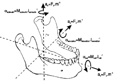
Lower jaw movements result from contraction of masticatory muscles. Each muscle applies a force, defined by magnitude, point of application and direction. The effects of muscular forces are the translation of the lower jaw along its line of action and the rotation about an axis normal to it, passing through the jaw’s center of gravity (Figure 1.5) [10]. However, the lines of action depend on the position of the lower jaw with respect to the skull, causing continuous changes in the forces and torques.
Figure 1.4 – Mouth closing masticatory muscles.
Figure 1.5 – Six degrees of freedom for jaw movement. Where: a=accelerations, F=forces, m=mass, α=angular accelerations, M=torques, I= moments of inertia.
14
Optimum isometric forces produced by muscles during contraction are proportional to its physiological cross-sectional area (PCSA) [14], according to the following law:
𝐹 = 𝐴 ∗ 𝐾 ∗ 𝑃𝐶𝑆𝐴
Where F is the muscular force [N], A is the percentage of activated fibers [%] and K is the musculoskeletal constant [N/cm²].
PCSA is the area of muscular cross-section perpendicular to fibers, generally at its largest point. It differs from the anatomical cross-sectional area (ACSA), which is the area of the cross-section of a muscle perpendicular to its longitudinal axis (Figure 1.6) [15].
PCSA is calculated as [17]:
PCSA =Muscle Volume
Fiber length
The constant K was obtained from a great variety of experimental animals and it seems to be constant for mammalian species. Its value ranges from 30 to 40 N of tension per square centimeter of PCSA [18].
ACSA
PCSA
Figure 1.6 – Difference between anatomical cross-sectional area and physiological cross-sectional area [16].
15
In addition to active elements, jaw movements are also controlled by passive structures, which resist to movements along one or more degree of freedom generating reaction forces. Passive elements include articular surfaces and ligaments, muscles, teeth and food [10].
During loading, the TMJs transfer reaction forces to mandibular condyles. Since the articular disk deformation is independent on loading direction [11], one can suppose these reaction forces are directed perpendicular to articular surfaces. For instance, in case of a static biting task, the condyles may be considered bounded in all the six degrees of freedom. Also articular ligaments contributes to increase joints stability, generating tensile forces when condyles move away from articular surface.
The second passive component is represented by muscles. It is known that total tension developed by a skeletal muscle is described by a length-tension relation similar to the one in Figure 1.7 [17]. Thus, total tension is the sum of two contributes: active tension, that is the amount of tension generated during contraction, and passive tension, that indicates the tension of unstimulated muscle at different lengths. Passive forces of the closing muscles are responsible of mandible deceleration at the end of jaw opening during mastication.
Other passive elements to consider are teeth and bolus, which directly influence jaw movements when upper and lower teeth come into contact, with or without food. Due to muscles and TMJs forces, the associated reaction forces are directed
16
vertically downwards [10]. The combination of active and passive components generates always bilaterally symmetrical condylar reaction forces [19].
1.2.3 Anatomy of sheep mandible
Preclinical trials are essential to the development of scientific technologies. Thus, in this study, sheep was chosen as a large animal model to perform preclinical trials for fracture treatments.
Like other mammals, sheep mandible is divided into zones, according to local functional activity. The mandibular body extends from angular regions to the symphysis, the alveolar process contains the teeth and the two rami that include the coronoid process, particularly pronounced, and the condyles. Unlike humans, sheep symphysis is a movable joint, thus the two parts of body region are partially fused together and are able to rotate around their own long axis (Figure 1.8).
1.2.4 Sheep masticatory system
Sheep dentition is divided into three tooth classes: molars and premolars, inserted into the alveolar processes in the body, and incisors, supported by alveolar bone in symphysis. Upper incisors are totally absent and a long edentulous region, called diastema, stretches between the anterior teeth and the cheek teeth. As herbivores, teeth morphology is associated to the feeding strategy [21]. Sheep
Temporalis Medial Pterygoid Masseter Lateral Pterygoid Digastricus Geniohyoid Mylohyoid
17
mastication is linked to a cutting process, characterized by compression followed by shearing movements. Flattened molars with ridges (Figure 1.9) are the results of the great intake of plant material, rich in cellulose, which requires a long processing.
Muscle involved in mastication are the same seen in humans, with differences in muscular attachments and proportions [22]. Three powerful jaw adductors are typically recognized: temporalis, masseter and medial pterygoid. Temporalis muscle pulls the mandible posteriorly during closing. The masseter may be divided into superficial masseter, responsible for pulling the mandible anteriorly while deep masseter posteriorly. The medial pterygoid has a similar effect of superficial masseter with an extra rotation movement of the two body regions in opposite directions. Another muscular force is given by the lateral pterygoid muscle that pulls the condyle anteriorly and medially. Less strong muscular forces come from the digastric and geniohyoid, involved in the opening movements, pulling down and back the mandible.
Rotational movements predominate in carnivores, where the joints act like a hinge (Figure 1.10a). On the contrary, masticatory movements in herbivores are predominantly translational [23] (Figure 1.10b), thus articular surfaces are flat, forming a track in the direction of movement. When mandible closes in sheep, condyles move posteriorly and the movement ends with the power stroke, during which mandible moves anteriorly and medially back to the midline. It is observed indeed in mammals that chewing occurs on one side (working side) at time.
18
Omnivores like humans present a combination of both rotational and translational movements.
1.2.5 Etiopathogenesis of mandibular trauma
The majority of the injuries around the world present the same etiologies (physical assault, motor vehicle collision, fall, sporting injury, etc). However, many studies have shown different distribution of such etiologies, based on the geographical area. For instance, in India more than 72% of trauma are due to vehicle accidents [24] or in Texas, Gutta et al. [25] observed that 80% of the fractures are caused by physical assaults. Other studies focus on other parameters such age, gender or drug intake.
The combination of all these outcomes represent fundamental aspects that can help surgeons to identify the most common patterns of injury. Morris et al. [26] observed that the most common anatomic sites of mandibular fracture are the angle with 27% and the symphysis with 21.3%. They also linked the fracture mechanism, based on the velocity of the hit, to the anatomic site.
19
These data show the importance of both, anatomical and biomechanical aspects, in mandibular fractures. For example, fractures to the parasymphysis are very common in case of blunt trauma impact, as the bone is weaker due to the presence in this area of canine long roots and mental foramen. Similar conditions apply to the angle of the mandible, in which the unerupted wisdom teeth reduce the mechanical strength of the bone.
1.2.6 Fracture healing
It is known that bone is one of the few tissues that can heal without forming a fibrous scar [7]. Following the initial trauma, fracture healing takes place by two possible ways: direct (or primary) healing and indirect (or secondary) healing [27].
The former occurs when the osteons of the fracture ends are in direct contact, allowing the bridging without callus formation. The latter is the most common pathway of fracture healing and it results from the mechanical instability of the fracture, characterized by resorption of fracture ends and callus formation. However, too much motion can result in delayed healing or non-union. In both cases, it usually takes from few months to years, before complete healing is achieved.
Therefore, for bone healing to be successful, two key factors must be taken into consideration:
20
• adequate blood supply, essential to hematoma formation and carrier of BMPs and growth factors [28].
• stable fixation, to start the healing process and eventually callus formation. Callus bone is extremely fragile and an excessive motion of fracture ends leads to breakage of it. However, micromovements can stimulate bone ingrowth [29]. Consequently, a balance between rigidity of osteosynthesis implants and interfragmentary movements must be found.
1.2.7 Mandibular fracture management
The goals of treatment of lower jaw fractures are: • Restoration of occlusion
• Recovery of function • Acceptable aesthetic
The gold standard for mandibular fractures management is the Open Reduction Internal Fixation (ORIF), developed by AO Foundation. First, it involves the exposure of broken bone and its consequent reduction, preventing bony fragments displacement. Next, an internal fixation device is placed on the bone, usually screws and plates made of titanium alloy Ti-6Al-4V, which shows an excellent resistance to corrosion and high biocompatibility as well as good mechanical strength [30].
Optimal osteosynthesis requires that:
• plates and screws must guarantee a stable fixation, withstanding stresses due to tensile and torsional forces applied to the bone.
• plates must be easily adaptable to bone surface, to ensure perfect anatomical reduction and to restore dental occlusion.
• plates must have minimum impact on the fracture site.
• screws must have an appropriate dimension for the thickness of the cortex. • as much as stability, preserving blood flow is another essential preventive
21
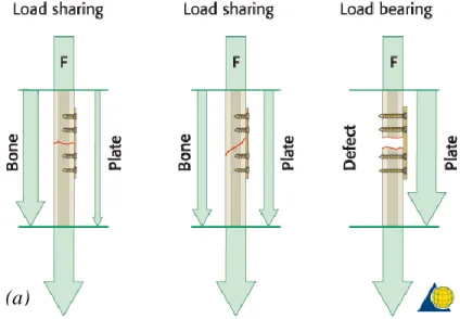
There are two general categories of fracture fixation: load-bearing osteosynthesis (Figure 1.11a) and load-sharing osteosynthesis (Figure 1.11b) [31] [32].
In the former, also known as rigid fixation, stabilization is made by splinting and the plate bears 100% of functional loads at the fracture site. The device must provide enough rigid fixation of the fracture ends, in order to create a suitable environment for the healing process. It is recommended in case of comminuted, pathologic, infected or defect fractures. Load-bearing plates include reconstruction plates, both locking and non-locking, and bicortical screws to guarantee maximal fixation, with ideally three or four screws placed on each side of the fracture. Disadvantages of this technique may include a stress-shielding effect on the underlying bone, in which the much stiffer metal plate protects bone from stress, gradually reducing its density.
In load-sharing osteosynthesis, the device shares approximately half of functional loads with bone. Stability is created by frictional resistance between the fracture ends and the plate. However, bony buttressing is not enough at the fracture site to allow the use of these plates with defect fractures or comminuted fractures.
(a) (b)
Figure 1.11 – (a) In a load-sharing situation, bone assumes most of the functional load; (b) treatment of a defect fracture, in which the osteosynthesis assumes all the masticatory loads.
22
1.2.8 Plating Systems: Nonlocking versus Locking Plates
Main types of plates used in mandibular fracture fixations are [32]: • Mandible plates 2.0 (conventional or nonlocking systems) • Locking plates 2.0
• Reconstruction plates (locking systems)
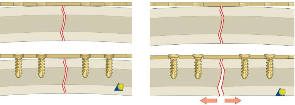
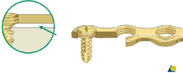
where the number following the name of the plate represents the screw diameter. While the application of reconstruction plates is based on load-bearing principles, the other two types of plates are representative of load-sharing osteosynthesis. Mandible plates 2.0 include systems of different lengths and shape (Figure 1.2), but they can only be used in combination with nonlocking screws. Miniplates, introduced by Michelet [33] and further developed by Champy [8], fall into this category and are referred to plates with a thickness lower than 1.5 mm. Since they are designed to be used with monocortical screws, miniplates are an example of load-sharing osteosynthesis. The nonlocking system requires they must be perfectly adapted to the underlying bone (Figure 1.12), otherwise segments alignment may be altered, i.e. loss of reduction, and a change in the occlusal relationship can occur [32].
According to AO’s principle, stability is one of the aims of osteosynthesis devices. Using nonlocking plates, a stable fixation is reached when the head of the screw compresses the fixation plate to the bone. However, as shown in Figure 1.13, having a precisely adapted plate may bring to a malreduction of the fracture.
23
Moreover, resorption of the cortex adjacent to the plate occurs due to stress-shielding effect.
Ideally, the system remains stable until the fracture is healed. However, if the plate does not perfectly adhere to the bone, the healing process may be slower than the cortex resorption and it may result in unstable fixation.
To overcome the need of an intimate contact between plate and bone and consequently the problem of fracture displacement, locking screw and locking plate systems have been introduced (Figure 1.14) [34].
Locking plate and screw systems have several other advantages over the conventional systems. First, no screw loosening occurs because the screw head is locked to the plate, even if, for example, the screw is inserted into the fracture gap. This results in decreased inflammatory complications and infection incidence due to loosening of the screws. Moreover, without a perfect adhesion, tightening of the screws will draw the bone segments toward the plate without altering the reduction.
24
Another possible advantage in locking systems is that, since plates are not compressed to bone surface, cortical bone perfusion is not compromised as much as in conventional plates, promoting in this way the healing process.
However, though locking plates have been shown to provide more stable fixation than conventional systems, they are still far from being the perfect treatment modality. Indeed, they have the same complication rates as nonlocking plates and their cost is significantly higher. Hence, miniplates remain a good option for treatment of mandibular fracture, since plate breakage occurs very rarely [35] and they are cheaper and readily available compared to other fixation systems.
1.2.9 Limitations of current treatments
The use of rigid or semi-rigid internal fixation may provide stabilization for bone graft in the area of continuity defects, with advantages that include good control of bone positioning to promote the healing process and immediate recovery of jaw function. However, current treatments showed some disadvantages and complications in mandibular reconstruction.
One of the main problems is the composition of plates and screws, made in titanium alloy Ti-6Al-4V. Despite their high biocompatibility, corrosion resistance and mechanical strength, titanium plates may induce a “stress-shielding effect” in the bony tissue [36]. This complication happens when fixation systems have a higher modulus of elasticity than the underlying bone. Titanium Young’s modulus is about 110 GPa [37], respectively one and order and two orders of magnitude higher than mandibular cortical bone and cancellous bone [38] [9].
25
Due to high rigidity, implanted plates protect bone from physiological stress, decreasing bone strength and compromising, in this way, implant stability. Another main limitation it is that titanium is not a biodegradable material which can be a big disadvantage when the hardware needs to be removed due to postoperative complications. Surgical removal of fixation devices may be challenging in case of hardware failure and when the bony tissue surrounds implanted plates and screws.
Moreover, the presence of metal implants may affect considerably postoperative image quality of both MRI and CT (Figure 1.15) [39]. The generated artifacts obstruct the bone and the other tissues from being visualized, causing a great disadvantage in case of pathologies that need a frequent monitoring, e.g. cancer.
Artifacts volume depend on the size, shape, composition and position of the implants with respect to the X-ray beams and magnetic fields of CT and MRI scanners respectively. Since titanium is a non-ferromagnetic material, Ti-implants should not have an influence on MR images. However, artifacts are always present due to traces of ferromagnetic iron in the titanium [40].
1.2.10 Magnesium in bone healing
Magnesium and its alloys represent a promising biomaterial for the fabrication of biodegradable osteosynthesis devices. In fact, since magnesium is naturally present in the human body, it is highly biocompatible and it is a promoter of the healing processes and osteogenesis [41] [42]. It is hypothesized that the corroding
26
magnesium enhances local bone regrowth through electrical stimulation of osteoblasts and supporting osteoconduction. Besides osteogenic properties, magnesium is a good candidate also for its antibacterial properties and mechanical properties, comparable with those of cortical bone, that provide enough stability and concurrently reducing stress-shielding effect.
First reported use of magnesium bone implants dates back to 1932, with Lambotte study [43]. It is known that, in biological fluids, magnesium corrosion follows two different cathodic reactions, one involved into Mg releasing, which promotes osteogenesis and anti-inflammatory response, and the other one responsible of hydrogen ions release [44]. The latter is often associated with gangrene of nearby tissues and requires a high blood flow to rapidly remove the excess gas. Moreover, in the last decades, other materials were preferred to magnesium also due to its high resorption rate (0.40 ± 0.04 mm/year [45]) that led to implant instability. Nowadays, magnesium alloys, in particular WE43 alloys, have gained renovated interest thanks to new coating techniques, grain refinement and the use of magnesium in combination with other elements. Since WE3 is a slow-rate corroding alloy, hydrogen bubbles may be easily removed by blood flow [46]. Moreover, Levorova et al. [47] made a comparative material study between Ti-6Al-4V and degradable WE43 screws. They observed that Mg screws improved bone regrowth in the first six to eight weeks of bone healing compare with titanium screws. However, lack of stability happens in WE43 screws after 12 weeks, versus the 48 weeks of PDLA for example [48], proving that more research about Mg implants must be done.
1.3 State of art
In order to comprehensively define and understand physical phenomena, most of them are studied and described using Partial Differential Equations (PDEs). Numerical solutions of PDEs can be obtained through different techniques and the most common one is the Finite Element Method (FEM). The Finite Element Analysis (FEA) simulates complex processes using FEM, providing an
27
approximation of the solution of the real problem, since it converts, under certain conditions, the PDEs system into an algebraic equation system [49].
In biomechanics and particularly in the study of bone regeneration, the FEA is a powerful tool to understand how bony tissue responds to mechanical stimuli. Performing a FEA means subdividing the analyzed structure into a large number of small elements of finite dimensions, all linked together and forming the “mesh”. Under certain loading and boundary conditions, in static situation, it is possible to determine stress and strain patterns inside the tissue and, consequently, to improve its behavioral knowledge.
Several studies used FEA to estimate the mechanical behavior of human mandible in healthy conditions. Korioth et al. [50] [51] developed one of the first 3D models of human dentate mandible for a complete characterization of different clenching tasks, for a given set of muscles, bite forces and joint forces. Commisso et al. [52] focused on the stress pattern inside the TMJ and the influence of lateral pterygoid muscle on lateral movements.
In the last decade, research was more focused on the analysis of the mandible in pathological conditions, which includes fractures, large defects, osteotomies and alveolar atrophy, and on the FEA of fixation systems used for their treatment. For example, Vajgel et al. [53] created a 3D model of an atrophic mandible with a simple fracture in the body region. They applied a reconstruction plate 2.0 to the fracture site and simulated three different thicknesses to find the best treatment strategy (Figure 1.16).
28
Other studies used finite element models to predict the failure location of an implant [54] or to compare the mechanical response of custom and optimized plates [56] and scaffolds [57] in case of segmental defects.
Several studies have investigated the mechanical behavior of human mandible using the FEA. However, just two cases of FE model of sheep mandible were found in literature. De Jongh et al. [58] used the first 2D finite element model of the lower jaw of domestic sheep to calculate the stress distribution, in a situation of maximum bite force, and to correlate it to the shape of the mandible. More recently, Li et al. [59] designed and applied a unilateral distraction device to the diastema of the sheep and used FEA to evaluate if the new stress distribution due to distraction osteogenesis could generate new bone in the defect (Figure 1.17).
To date, there is no study applying the FEA to the sheep mandible in healthy conditions or investigating the effect of different fixation systems on fracture healing in sheep mandible. This project proposes to fill this gap, laying the basis for using sheep as a large animal model also in future studies.
29
1.4 Aim
The general aim of this work was to investigate the mechanical conditions in fractured mandible, treated with fixation systems made of traditional titanium alloy and new magnesium alloy.
More specifically, I aimed to:
• compare strain distributions in human and sheep mandible, in order to understand if sheep may be a good candidate for preclinical testing of the new devices;
• study strain distributions within the mandibular fracture, to determine the level of mechanical strains under which healing takes place and how it is influence by fixation device properties (plate thickness and plate material properties).
• study stress distributions within the fixation systems, to evaluate the potential of magnesium alloy for the treatment of mandibular fractures.
30
2.
MATERIALS AND METHODS
In this project, Finite Element Analysis (FEA) was performed to investigate the biomechanical behaviour of load-sharing fixation systems in fractured mandible, with different design parameters. To achieve this purpose, 3D finite element models of human and sheep mandibles were developed to study stress and strain patterns in healthy and pathological conditions. Specifically, a simple fracture in the body region was simulated in both models and treated with 4-hole miniplates 2.0, according to AO’s guidelines.
Two parameters were modified during the analysis in fractured mandible: implants biomaterial and thickness of the plates. Due to the renewed interest in magnesium alloys for clinical applications, the objective of the study was to assess if WE43 alloy may be an alternative to titanium alloys fixation systems, despite the inferior mechanical properties. Therefore, stress and strain distributions induced at the fracture site were compared in WE43 fixation devices and Ti-6Al-4V traditional implants, at two different miniplate thicknesses (1 mm and 1.5 mm).
The mandible models were created in commercial software AMIRA and the same volumetric mesh was used for healthy and fractured mandible in human and sheep. The design and positioning of the implants were performed in Solidworks, while Abaqus was used to assembly the components and to execute the FEA.
2.1 Mandibular Geometry
The bone geometries used for the project belong to a 60-year-old woman and to an 18-month-old sheep of the species Ovis aries, both in healthy condition.
Cone-31
beam computed tomography (CBCT) scans of the human and sheep head were used for the model creation. CBCT has been introduced in the past decades and widely used in dentomaxillofacial imaging due to the significantly smaller dose of ionizing radiation for a head scan (dozens of μSv) compared to CT (from hundreds to thousands of μSv), although it implies a reduced spatial resolution [59] [60].
2.1.1 Segmentation
The DICOM images resulting from the scans were imported into the software AMIRA, which first allowed the 3D visualization of the images. By thresholding, it was possible to differentiate between hard and soft tissues based on the grey-scale values of the images (Figure 2.1). In fact, the brightness of the pixels is correlated to the mineralization of the tissue, with hard mineralized bone associated to lighter pixels and soft tissues to darker ones. AMIRA automatically generates a histogram based on grey-scale value distribution, which was used to select a threshold value to separate the skull from the surrounding tissues, compromising between noise reduction and accuracy of bone selection.
32
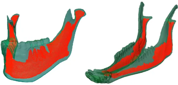
Next, a combination of automatic and manual segmentation tools was used to extrapolate the mandible and to differentiate the mineralized tissue into cortical and trabecular bone (Figure 2.2).
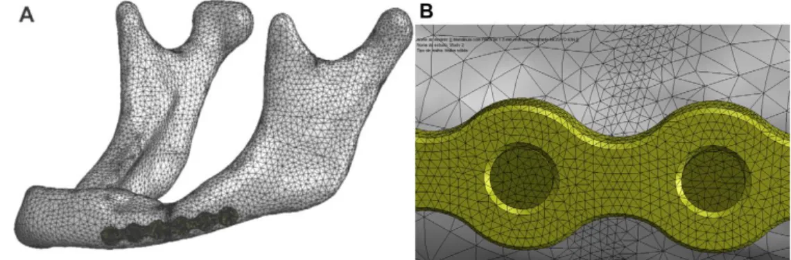
2.1.2 Meshing process
The final goal of geometry reconstruction was the generation of a volumetric mesh of the bony tissues, which could be exported to Abaqus, a software for FEA. The first step was to create surfaces of cortical and cancellous bone based on the LabelVoxel module of Amira, obtained after the segmentation process. During this phase, smoothing of the asperities and removal of the artefacts were performed. Since the obtained surfaces consisted of a high number of triangular faces, in order to reduce the computational burden, surface simplification and remeshing were performed.
Before launching the FE mesh generation, any intersections and bad orientations of the remeshed surfaces were fixed. Moreover, the triangle quality and aspect
Figure 2.2 – Segmented bone geometry of (a) human mandible and (b) sheep mandible, where cortical bone is shown in green and trabecular bone in red.
33
ratio were improved, by modifying the triangles manually or with automatic tools until their values were inferior to 25 or 10, respectively.
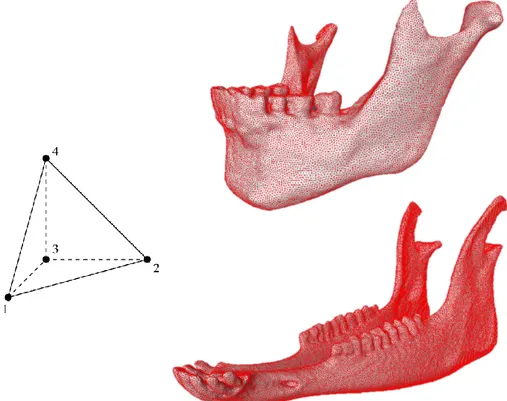
Only after these criteria were respected, the volumetric mesh of cortical and trabecular bone was generated using the TetraGen function in AMIRA (Figure 2.3). AMIRA then creates a linear mesh, composed by four-node tetrahedral elements (C3D4), stiffer than quadratic elements, which can be used in structural calculations if their number is sufficiently high [61]. In this study, human mandible was meshed in 884,361 tetrahedrons and the sheep mandible in 1,044,604 tetrahedrons. This very high number of elements made a convergence test unnecessary, since previous studies with similar tetrahedral FE meshes of human mandibles showed that a reasonable accuracy can be reached with a much smaller number of elements (<100,000) [62] [63].
At the end of the meshing process, the generated grid was saved as INP file and exported to Abaqus for the finite element analysis.
34
2.2 Finite element model of human and sheep healthy mandible
The INP file was imported into Abaqus as an orphan mesh, meaning that it has no associated geometry and re-meshing or mesh refinement is not possible. Moreover, the mandible was imported as a model, preserving in this way the information about the elements associated to the two materials defined in Amira. 2.2.1 Material properties
After geometry reconstruction, different material properties were assigned to the cortical bone, trabecular bone, miniplates and screws. Although the Young’s module of mandibular cortical bone is known to have an orthotropic distribution with regional variations [9], to simplify the numerical simulations (and according to the level of detail required), all materials were considered isotropic, homogeneous and linear elastic (as referred from previous researches [64] [65]). For cortical and cancellous bone in the human mandible, a great variability of Young’s module values and Poisson’s ratios were observed in the literature. This may be due to the hypothesis at the base of the experimental testing, sample damage, different pick-up locations or different hydration states [66]. The values used in this study were obtained from Ayali et al. [64], in agreement to the range found in other experimental studies [9] [66].
Due to a lack of information in the literature about bone tissues properties in sheep mandible, material properties in this study are based on the work of Li et al. [67], in which these parameters were calculated using the relationship between Hounsfield Units (HU) values of CT, apparent density and Young’s module.
Young’s modulus (MPa) Poisson’s ratio
Human cortical bone 14,800 0.30
Human trabecular bone 1,850 0.30
Sheep cortical bone 15,750 0.30
Sheep trabecular bone 300 0.30
35 2.2.2 Boundary Conditions
Boundary conditions (BCs) were applied to the contact regions between the upper jaw and the skull. In order to distribute the BCs on all the nodes of a surface, they were applied to a reference point, defined on these surfaces, and kinematic coupling constrains were used to link the motion of the reference point to the motion of the nodes.
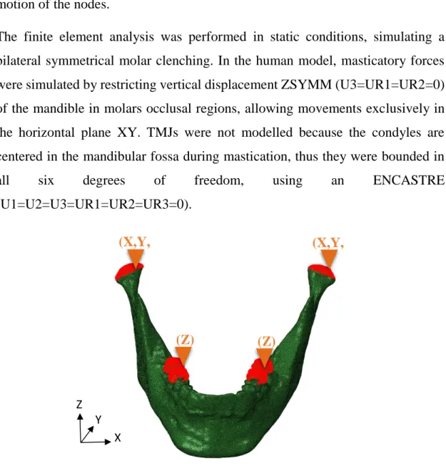
The finite element analysis was performed in static conditions, simulating a bilateral symmetrical molar clenching. In the human model, masticatory forces were simulated by restricting vertical displacement ZSYMM (U3=UR1=UR2=0) of the mandible in molars occlusal regions, allowing movements exclusively in the horizontal plane XY. TMJs were not modelled because the condyles are centered in the mandibular fossa during mastication, thus they were bounded in
all six degrees of freedom, using an ENCASTRE
(U1=U2=U3=UR1=UR2=UR3=0).
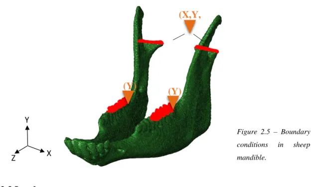
Likewise, in the sheep model the same strategy was adopted, however a new datum system was created, since the head of the sheep was not aligned to the anatomical planes during the CBCT scan. Hence, the boundary conditions were referred to the relative datum system shown in Figure 2.5 and the vertical
Figure 2.4 – Boundary conditions in human mandible.
(X,Y, Z) (X,Y, Z) (Z) (Z) X Y Z
36
displacement at the molars was restricted along the vertical direction YSYMM (U2=UR1=UR3=0), while the condyles were assumed fixed as an encastre.
2.2.3 Loads
Loading conditions in both mandibles were simulated through the application of specific force vectors for each closing muscle used during mastication. As vectors, forces are defined by their magnitude and direction and the resultant vector, given by the sum of all the forces, represents the bite force produced in the occlusal region.
In human, maximum force magnitudes were taken from Nelson [14] (Table 2.2), whose work is based on the Physiological Cross-Sectional Areas (PCSAs) of jaw muscles found by Weijs et al. [15] [17].
HUMAN Maximum Muscle Force (N)
SM 190.4 DM 81.6 AT 158.0 MT 95.6 PT 75.60 MPt 174.8 LPt 66.9
Table 2.2 – Maximum muscular forces in human mandible.
X Y Z Figure 2.5 – Boundary conditions in sheep mandible. (X,Y, Z) (Y) (Y)
37
Seven muscular groups were identified as responsible for closing movements: superficial masseter (SM), deep masseter (DM), anterior temporalis (AT), medial temporalis (MT), posterior temporalis (PT), medial pterygoid (MPt), lateral inferior pterygoid (LPt).
In sheep, since no data were found in the literature, muscular forces were obtained using the same approach used by Nelson. In order to calculate the PCSA of jaw muscles, firstly an MRI scan was performed on the same sheep head used for the initial CBCT scan. By importing the DICOM images into Amira, it was possible to operate a segmentation of the different muscular groups (Figure 2.6) and to extract their volumes and maximum fiber lengths to calculate the PCSAs. The poor resolution of the MRI did not allow segmentation of the temporalis muscle (TEMP) in the three groups, as in the human model. Subsequently, PCSAs were multiplied by the musculoskeletal constant of 40 N/cm², which is valid for all mammals [14].
However, in human, the forces normally applied to the mandible are much smaller than the maximum bite force, which ranges 500-700 N in the molars [68]. Moreover, they can vary drastically with the type of food that is being chewed [20]. For instance, Koyhama et al. [69] reported a range of force between 50 and
Figure 2.6 – (a) Lateral view and (b) internal view of sheep muscles, reconstructed from an MRI: superficial masseter in blue, deep masseter in light blue, temporalis in green, medial pterygoid in
38
150 N according to food hardness. To study the mechanical behaviour of human mandible, a resultant force of approximately 100 N was simulated at the occlusion surface, reducing the muscular forces to 25% (Table 2.4). The same percentage was used to model the forces in the sheep mandible (Table 2.5).
SHEEP Muscle Volume (cm³) Fiber Length
(cm)
Maximum Muscle Force (N) SM 87.1 13.0 267.4 DM 12.4 4.0 124.9 TEMP 40.8 10.8 151.5 MPt 42.80 11.52 148.48 LPt 4.70 3.35 56.19
HUMAN Applied Muscle Force (N)
SM 47.6 DM 20.4 AT 39.5 MT 23.9 PT 18.9 MPt 43.7 LPt 16.7
SHEEP Applied Muscle Force (N)
SM 66.8
DM 31.2
TEMP 37.9
MPt 37.1
LPt 14.1
Table 2.3 – Maximum muscular forces in sheep mandible.
Table 2.4 – Applied muscular forces in human mandible.
39
Force directions were obtained considering the muscular attachments in the lower jaw and in the skull. In human, the location and extension of the surfaces of muscular attachments were qualitatively reproduced based on literature [50] [70]. In sheep, the lack of data required an anatomical dissection of the sheep head in order to identify the attachments and the direction of the muscular fibers.
Once the muscular anatomic regions were clarified, whole human and sheep skulls were segmented in Amira and exported to ABAQUS. It was then possible to create the reference points associated to the muscular attachment on the mandible and skull. Using these coordinates (Figure 2.7), referred to the global datum systems, the directions of force vectors were finally obtained (Table 2.6 and Table 2.7).
HUMAN Left Side Right Side
x y z x y z SM 0,13 -0,54 0,83 -0,13 -0,54 0,83 DM 0,44 -0,02 0,90 -0,44 -0,02 0,90 AT 0,19 0,21 0,96 -0,19 0,21 0,96 MT 0,37 0,37 0,85 -0,37 0,37 0,85 PT -0,31 -0,06 0,95 0,31 -0,06 0,95 MPt 0,06 0,07 0,99 -0,06 0,07 0,99 LPt -0,71 -0,49 -0,50 0,71 -0,49 -0,50
Figure 2.7 – Direction of the force of superficial masseter in sheep.
40
The force vectors were applied to the bone at the corresponding muscular attachments, defined as surfaces in Abaqus. In human, the relative extensions of the attachments were obtained from literature [50] [70] (Figure 2.8a), while for the sheep model they were deduced from anatomical dissection and MRI scan (Figure 2.8b).
SHEEP Left Side Right Side
x y z x y z SM -0,93 0,30 -0,22 -0,89 0,41 -0,22 DM -0,81 -0,27 0,52 -0,37 0,67 0,68 TEMP 0,23 0,02 0,97 0,17 -0,25 0,95 MPt -0,66 0,75 0,11 -0,99 -0,10 0,03 LPt -0,14 0,50 -0,85 -0,34 -0,15 -0,93
Figure 2.8 – Muscular attachments in (a) human mandible and (b) sheep mandible. SM DM LPt MPt TEMP SM DM LPt MPt PT MT AT
Table 2.7 – Coordinates of force vectors in sheep mandible, referred to the datum system of the CT images.
41
2.3 Finite element model of human ad sheep plate-fixated fractured
mandible
2.3.1 Modeling fractured mandible
In the human, the fracture was between the premolar and the first molar in the left side of the mandible, while in the sheep it was simulated between the first and the second molar in the left side, for space reasons.
The fracture lines were simulated in Abaqus by defining an element set on the orphan mesh of the mandibles (Figure 2.9). Three measurements of the distance between the fracture ends were taken at the top, middle and bottom part of the mandibles. The average fracture depth was 1.6 mm in human and 1.5 mm in sheep.
42 2.3.2 Modeling Plate Fixation
2.3.2.1 Geometry
Geometry construction of fixation systems was based on the design of commercially available devices and performed using the 3D-CAD software SolidWorks.
The 4-hole miniplates 2.0 were designed with two different thicknesses (1.0 and 1.5 mm), while the screws were modelled in a simplified version without threading, with the diameter of 2.0 mm according to the plate type (Figure 2.10).
2.3.2.2 Positioning on the mandible
The positioning procedure of the fixation systems was similar for both models. First the fracture sites in the body regions were defined as described above. Following AO’s guidelines [32], two miniplates were applied to the bone, since this approach been shown to provide higher stability than a single plate. The superior border plate was positioned on the ideal line of osteosynthesis based on Champy’s principles [8], while the inferior border plate was placed at the base of the mandibular body, both parallel to the mandibular canal.
To position the fixation systems on the mandible, the surfaces of the latter were exported from Amira (as STL files) and then imported into Solidworks as solids. Here, the pre-designed plates were first slightly bent and twisted in order to adapt
(a) (b) Figure 2.10 – (a) 4-hole miniplate 2.0 and (b) screw 2.0.
43
them to the irregular surface of the bone before inserting four screws into each plate (Figure 2.11).
Next, the 3D assembly was positioned in good contact to the mandibular surface (Figure 2.12), as required for conventional (nonlocking) systems.
Figure 2.11 – Assembly of miniplate and screw.
44
The fixation systems assembly was then exported from Solidworks (as STEP files) and imported as separated parts into Abaqus. Since the global datum system of the mandible imported from Amira and the assembly from Solidworks are the same, the latter maintains the position defined in Solidworks.
2.3.3 Material properties in the fractured mandible
To simulate the fractures in the body regions, the mesh elements inside the fracture gap were considered to have the mechanical behaviour of granulation tissue (Table 2.8), since they were assumed to represent the initial phase of the inflammatory response [71].
Concerning the implants, two different metallic materials were assigned to the miniplates and screws: titanium alloy Ti-6Al-4V and magnesium alloy WE43. Considering the reduced stiffness of WE43 alloy, the miniplates were designed in the thickness of 1 mm (standard) and 1.5 mm (increased cross-sectional area). Material properties were taken from the MatWeb [72] online database and are reported in Table 2.8.
2.3.4 Meshing process
In Abaqus, the fixation devices were meshed using 10-node quadratic tetrahedrons (C3D10) (Figure 2.13). The same seed density was defined for all the screws, while smaller seeds were required for the plates due to the more complex geometry and to the previous handling, necessary to adapt them to the bone surface.
Young’s modulus (MPa) Poisson’s ratio Fracture gap
(Granulation tissue) 1 0.30
Ti-6Al-4V 11,0000 0.34
WE43 44,000 0.27
45 2.3.4 Constrains
In order to fix the plates to the bone tissue, tie constrains were applied between screws, bone and plates. This type of constrain allows to fuse together two regions, to have no relative motion between them, even though the meshes created on the surfaces of the regions may be dissimilar.
In this study, a tie constrain was applied between a geometry set created from the screws and a node set, which included all the nodes of the orphan mesh of the bone. A second tie constrain was used to fix the head of the screws to the holes of the miniplates. It was applied between the same geometry set of the screws defined in the previous step and the holes surfaces of the miniplates, as shown in Figure 2.14. Since Abaqus’s guidelines [23] suggest, in tie constrains, to choose as master surface the stiffer and less densely meshed part, the screws were in both cases selected as master, while bone and plates as slave.
Figure 2.13 – Ten node tetrahedral element (C3D10) used to mesh the fixation devices.
46
3.
RESULTS
In this thesis, Finite Element Analysis (FEA) was used to investigate:
• differences in the mechanical behaviour between human and sheep mandible under clenching loading in healthy conditions;
• the mechanical conditions within a human mandible fracture stabilized using miniplates with different thicknesses and materials
• differences in the mechanical conditions within a fracture in human and sheep mandible;
• the risk of fixation failure for different materials and fixation design configurations.
In the fractured model, eight scenarios with different biomaterials and miniplate thicknesses were simulated, as shown in Table 3.1.
Biomaterial Miniplate Thickness (mm) Abbreviations
Human mandible Titanium alloy Ti-6Al-4V 1 H-T-1 1.5 H-T-1.5 Magnesium alloy WE43 1 H-W-1 1.5 H-W-1.5 Sheep mandible Titanium alloy Ti-6Al-4V 1 S-T-1 1.5 S-T-1.5 Magnesium alloy WE43 1 S-W-1 1.5 S-W-1.5
47
3.1 Mechanical behaviour of human and sheep mandible under
clenching loading
The results of the analysis allowed us to evaluate how the muscular forces affect the internal strain distribution in human and sheep mandible.
First, the reaction forces (RF) at the reference points constrained to the molar regions were calculated in order to obtain the magnitude of the applied bite forces (Table 3.2).
However, in this study the main interest was to analyse the strain distribution within the bone. Our results showed that the clenching loading conditions brought the mandible bone into compression, both in human and sheep.
It was observed that the strain distribution in the intact mandible was essentially symmetrical. The results show that the highest minimum principal strains were located, in both mandibles, on the anterior and posterior areas of the condylar neck (Fig. 3.1). Under clenching loading conditions, we determined very small deformations in the angle region, both in human and sheep. In the body regions, strains in the range of 100 με were predicted in both the human and sheep mandible. In the sheep mandible, lower strains of 30 με were also predicted anteriorly, in the diastema.
Reaction force left side (N) Reaction force right side (N)
Human 100 105
Sheep 102 92.7
48
49
50
3.2 Fractured sheep mandible stabilized with miniplates
3.2.1 Strain Distribution within the fracture gap
The von Mises stress is used to predict yielding of materials under complex loading. In this thesis, von Mises stress was calculated inside the miniplates and screws as an indicator of the mechanical performance of the various fixation systems, during molar clenching.
A cross-sectional view of the strain distribution inside the bone tissue at the fracture site is reported in Figure 3.4. As in the previous case, the fracture gap was subdivided into three regions: inferior part (IP), middle part (MP), crestal part (CP) and mean values were obtained considering the local and global strains. As shown in Table 3.3, the most compressed regions were the inferior and crestal part, with the highest absolute values of strains in the former. The middle part, where the plates are located, showed values lower than the average in the total gap. Regarding the fixation systems, mean strain values in the fracture gap ranged between 400-500 με. The fracture treated with magnesium implants was subjected to greater strain than fractures treated with titanium implants, with mean strains 0.02% and 0.07% higher in 1 mm and 1.5 mm thick miniplates, respectively. Moreover, the thicker the plates, the lower the strains. The maximum strain value of 819 με was reported at the inferior part in S-W-1, while the minimum of 331 με was found at the middle part in S-T-1.5.
51
S-Ti-1 S-Ti-1.5 S-W-1 S-W-1.5
Inferior Part Middle Part Crestal Part Total gap S-T-1 -8.31E-04 -3.87E-04 -7.56E-04 -5.52E-04
S-T-1.5 -6.89E-04 -3.31E-04* -6.28E-04 -4.64E-04
S-W-1 -8.89E-04 ͯ -3.99E-04 -7.78E-04 -5.76E-04
S-W-1.5 -8.19E-04 -3.76E-04 -7.22E-04 -5.36E-04
Figure 3.4 – Minimum principal strain distribution within the fracture gap.
Table 3.3 – Mean values of strain distribution within the fracture gap, with (*) min value and ( ͯ ) max value.
CP
MP
52
3.2.2 Von Mises stress distribution in the fixations systems
3.2.2.1 Von Mises stress in the miniplates
High concentration of stresses was observed at the constrained regions between plates and screws. The maximum von Mises stresses in all cases did not exceed the yield strength of the titanium and magnesium alloys (Figure 3.5).
The stress patterns in both miniplates was observed. As in the human mandible, higher concentrations were found in the area between the second and third hole in sheep.
S-Ti-1 S-Ti-1.5
S-W-1 S-W-1.5
Figure 3.5 – Von Mises stress distribution in top miniplate (A) and bottom miniplate (B).
A B A B A B A B
53
A magnification of the central region of the miniplates B is shown in Figure 3.6. Peak von Mises stresses were not symmetric with respect to the fracture line. In particular, highest values were observed in titanium rather than magnesium and in the thinner plates.
S-Ti-1 S-Ti-1.5
S-W-1 S-W-1.5
In general, miniplates A were subjected to slightly higher stress (Figure 3.7). Peak von Mises stresses were observed in the titanium plates.
S-Ti-1 S-Ti-1.5
S-W-1
S-W-1.5
Figure 3.6 – Peak Von Mises stress in the central region of bottom miniplates.
B B B B A A A A
54
3.2.2.2 Von Mises stress in the screws
The maximum screw stresses were situated in the region of the head, where screws and plates are constrained (Figure 3.8). The peak von Mises stress was located in the bottom miniplates for all the cases and, in particular, at the screw n. 7 for the 1 mm thick plates and at screw n. 6 for the 1.5 mm thick plates. The reported values were far less than the yield strength of the used biomaterials. At the same thickness, slightly higher values were shown in titanium screws compared to magnesium screws. Likewise, higher stresses were present into the screws used in combination with 1.5 mm thick plates.
S-Ti-1 S-Ti-1.5
S-W-1 S-W-1.5
Figure 3.8 – Von Mises stress distribution within the screws.
1
5 6 7 8 2 3
55
3.3 Fractured human mandible stabilized with miniplates
3.3.1 Strain Distribution within the fracture gap
The fracture gap was mainly under compression with higher strains in the most crestal region (Fig. 3.9). Mean strain values were in the range between 1500 and 2500 με for the different plate configurations investigated (Table 3.4). In the most crestal region, mean strain values were in the range between 4000 and 6500 με (Table 3.4). Interestingly, thinner plates led to lower mechanical strains within the fracture gap, both for titanium and magnesium plates (Table 3.4). Magnesium plates let to higher mechanical strains within the fracture gap compared with titanium plates (Table 3.4), with mean strains 0.06% higher.
H-Ti-1 H-Ti-1.5 H-W-1 H-W-1.5
Figure 3.9 – Minimum principal strain distribution within the fracture gap.
CP
MP