ABSTRACT
The present research study is focusing on the evaluation of the integrated membrane system which merges the membrane contactor technology such as gas-liquid membrane contactors (GLMC) and membrane distillation /crystallization (MD/MDC) with the conventional pressure-driven membrane operations such as micrfiltration/ultrafiltration (MF/UF), nanofiltration (NF) and reverses osmosis (RO) within the logic of Process Intensification (PI) strategies in order to redesign the desalination plants to be cheaper, safer and sustainable. The importance of applying the PI strategies in the desalination industry is presented in chapter 1. In addition, this chapter gives the research project objectives and activities.
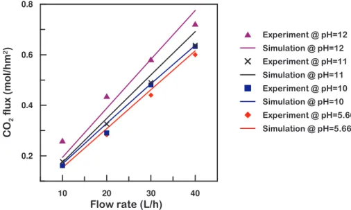
The optimization and the feasibility of using the GLMC in the proposed integrated membrane system were discussed in chapter 2. Simulation model for the GLMC was implemented by computer and the results were verified by experimental tests. The results showed that there was a good agreement between the simulation and experimental results with less than 10% differences. In terms of CO2 transfer rate, the results showed that higher transfer rates were obtained
at higher liquid flow rates and higher pH values due to lower mass transfer resistance and higher reaction rates, respectively. The feasibly study showed that using GLMC is more economically feasible since the cost of the NaOH used in the GLMC after reacting with CO2 to produce Na2CO3 was less than the cost of
using Na2CO3 directly from the market in order to precipitate Ca+2 as CaCO3.
Moreover, the GLMC will contribute to the reduction of CO2 emission from
desalination plants and reduce their environmental impact.
Since so far there are no membrane modules especially made for MD, the aim of this study was to provide optimization guidelines for materials and methods for using MD in desalination. Therefore, in chapter 3, comprehensive theoretical analysis have been carried out and simulation model was developed to describe the mass flux and heat efficiency in MD processes considering transport phenomena, membrane structural properties and most sensitive process parameters, with the aim to investigate the effects of the membrane properties on the MD performance and to set some criterions to optimize these properties in order to obtain the best performance. Experimental tests were conducted in order to validate the results obtained by the computer simulation and the results showed that the computer simulations were able to estimate the MD performance with errors not exceeding 5%. The results showed that an increase of the temperature gradient resulted in the enhancement of both transmembrane flux and thermal efficiency. On the other hand, feed concentration had low effects in flux reduction even at high values close to saturation which contribute to only 30-50% flux reduction. This makes the MD
process attractive technique for seawater desalination especially when integrated with RO in the logic of the ZLD concept and satisfying the process intensification goals. The investigation of the effects of membrane properties confirmed that better MD performance was achieved when using polymeric membranes characterized by low thermal conductivity (flux and thermal efficiency declined by 26% and 50%, respectively, when increasing thermal conductivity from 0.1 to 0.5 W/m K), lower thickness (increasing the membrane thickness from 0.25 to 1.55 mm resulted in a flux decay of about 70% without a significant improvement in thermal efficiency), and high porosity. The investigation of the complex correlations between physico-chemical properties of the membrane and MD performance confirms the need for a customized hardware, i.e. high porosity hydrophobic membranes with appropriate thickness and made by low-heat conductive polymers in order to reduce the amount of wasted energy.
The basic mechanisms and kinetics of crystallization were considered in chapter 4 in order to accomplish the modeling and simulation for the membrane crystallizers. The computer simulation of the MDC was similar to the one of the MD presented in chapter 3 with addition of crystallization kinetics calculation. The simulation model was used in parallel with the experimental tests in order to improve the design and performance of the crystallizers. The results showed that it was possible to obtain NaCl crystals from the NF retentate at a good quality and narrow crystal size distribution (CSD). The effects of the concentration polarization in the transmembrane flux were very limited; however, there was an unexpected flux decline after the formation of the crystals in the system. This was due to the deposition of the salts crystals on the membrane surface which caused pore blockage and hence flux drop. The design improvement of the MDC suggested to introduce another opening at the bottom of the crystallizer tank for removing crystals, and to install a filter in the suction side of the feed pump in order to avoid crystals for recirculation inside the membrane module with the feed.
Exergy analysis, economical investigation and sensitivity study were carried out in chapter 5 to evaluate the feasibility of the integrated membrane system. The exergy analysis showed that the highest work input was for the plant which involved the pressure-driven membranes UF-NF-RO due to the high pumping and pressurizing energy requirement especially in NF and RO pumps. On the other hand, the highest heat energy input was associated with the membrane distillation plant as a stand alone process. The exergy efficiency was generally higher in case of pressure-driven operations than thermal processes. In addition, the performance of plants with energy and heat recovery systems was always better than the ones without energy and heat recovery systems.
Economical study and cost evaluation for several configurations showed that the lowest total water costs were 0.51 and 0.29 $/m3 when using UF-RO
plant with energy recovery system for seawater and brackish water desalination, respectively. In case of the integrated system which contained both pressure and thermal processes, the best combination was obtained when using the pressure-driven membranes combined with a membrane crystallization unit operating on the NF concentrated stream and a membrane distillation unit operating on the RO brine stream. The total water cost in this case was 1.27 $/m3 and 1.10 $/m3
for seawater and brackish water, respectively. Moreover, the combination of membrane crystallization units is very attractive especially if the salt crystals produced by the crystallization process are considered. This means that the desalination plant will produce both water and salt crystals. In this case, the price of the salts can cover the whole expenses of the desalination process. Besides, the problems related to brine disposal were minimized when using the integrated membrane system.
The sensitivity analysis revealed that the pressure-driven membrane operations were very sensitive to the feed concentration and the cost of electricity. On the other hand, MD processes were not sensitive to the variation on the feed concentration or the electricity costs. The most sensitive parameter in the total water cost of the MD plant was the cost of steam which contributed to values as high as high as 11.4% in case of MD without heat recovery system. The best tolerance to the variation of these parameters was obtained when using the integrated membrane system of pressure-driven membranes and MD/MDC processes.
The realization of the semi-pilot plant of the integrated membrane system was covered in chapter 6. The semi-pilot plant of the integrated membrane system was designed and assembled based on the results obtained by the computer simulations and the preliminary experiments done for each unit individually in the previous chapters. It consisted of UF-NF-RO as the pressure-driven membrane operations with the GLMC for Ca+2 precipitation and an MDC
unit which can be operated as an MD or as a membrane crystallizer. The semi-pilot desalination plant of the integrated membrane system was operated using synthetic and real seawater in order to confirm the performance and process stability. The transmembrane flux was stable during the operation. The MDC was able to produce salt crystals from the NF retentate and the RO brine streams. The CSD of the crystals obtained by the MDC operating on the RO brine showed sharper distribution trends than the ones obtained from the MDC when operating on the NF retentate. In addition, the MD unit was operated as a stand-alone desalination process using real seawater and the results showed that it was stable and the membrane did not loss its hydrophobicity during the operation.
SOMMARIO
Il presente studio è incentrato sulla valutazione del sistema integrato a membrana in cui la tecnologia dei contattori a membrana (tipo i contattori gas-liquido (GLMC) e la distillazione/cristallizzazione a membrana (MD/MDC)) viene combinata con le operazioni convenzionali a membrana indotti dalla pressione (come la microfiltrazione/ultrafiltrazione (MF/UF), nanofiltrazione (NF) e l’osmosi inversa (RO)) nella logica della Intensificazione del Processo (PI) al fine di ridisegnare gli impianti di desalinazione per essere più convenienti, sicuri e sostenibili. L'importanza di applicare le strategie del PI nella dissalazione industriale è presentata nel capitolo 1 del presente lavoro. Questo capitolo fornisce inoltre gli obiettivi e le attività del progetto di ricerca.
L'ottimizzazione e la possibilità di utilizzare i GLMC nel proposto sistema integrato a membrana sono stati discussi nel capitolo 2. La simulazione del GLMC è stato effettuato tramite calcolatore e i risultati sono stati verificati tramite prove sperimentali. I risultati hanno dimostrato che vi è stato buon accordo tra la simulazione e risultati sperimentali con differenze inferiori al 10%. In termini di velocità di trasferimento di CO2, i risultati ottenuti hanno mostrato che le velocità
più elevate si hanno per portate di liquido alte e ad alti valori di pH a causa, rispettivamente, della minore resistenza al trasferimento di materia e alla maggiore velocità di reazione. Lo studio condotto ha mostrato che l'uso del GLMC è più economicamente conveniente in quanto, il costo per l’NaOH da utilizzare nel GLMC per produrre Na2CO3 è inferiore al costo che si avrebbe se l’Na2CO3 fosse acquistato
tal quale dal mercato. Inoltre, il GLMC contribuirà alla riduzione delle emissioni di CO2 dagli impianti di desalinazione e ridurrà il loro impatto ambientale.
Poiché finora non vi sono moduli a membrana appositamente realizzati per la MD, l'obiettivo di questo studio era quello di fornire le linee guida per l'ottimizzazione dei materiali e dei metodi per utilizzare la MD nella dissalazione. Pertanto, nel capitolo 3, sono state effettuate approfondite analisi teoriche ed è stato inoltre sviluppato un modello di simulazione per descrivere il flusso di materia e l’efficienza termica nel processo di MD considerando i fenomeni di trasporto, le proprietà strutturali della membrana e i parametri più sensibili del processo, con l'obiettivo di indagare gli effetti delle proprietà della membrana sul rendimento del processo di MD e di fissare alcuni criteri per ottimizzare queste proprietà al fine di ottenere le migliori prestazioni. Prove sperimentali sono state condotte al fine di convalidare i risultati ottenuti tramite la simulazione al computer ed i risultati hanno mostrato che le simulazioni al computer sono state in grado di stimare il rendimento della MD con errori non superiori al 5%. I risultati hanno dimostrato che un aumento del gradiente di temperatura ha portato all’accrescimento sia del flusso transmembrana che dell’efficienza termica. D'altro canto, la concentrazione dell’alimentazione ha un effetto inferiore sulla riduzione del flusso anche a valori elevati vicino alla saturazione, e contribuiscono a solo il 30-50% di riduzione di flusso. Questo rende il processo di MD una tecnica interessante per la dissalazione
dell’acqua di mare, in particolare quando integrata con la RO nella logica del ZLD per soddisfare gli obiettivi della Intensificazione del Processo. L'indagine degli effetti delle proprietà della membrana hanno confermato che la MD mostra un migliore rendimento quando si utilizzano membrane polimeriche caratterizzate da una bassa conducibilità termica (flusso ed efficienza termica sono diminuiti, rispettivamente, del 26% e 50%, quando la conducibilità termica aumenta da 0,1 a 0,5 W/m K), da un più basso spessore (aumentando lo spessore della membrana da 0,25 a 1,55 millimetri si ha un decadimento di flusso di circa il 70% senza un significativo miglioramento nel rendimento termico), e da alta porosità. L'analisi delle complesse relazioni tra le proprietà fisico-chimiche della membrana e le prestazioni della MD conferma la necessità di realizzare membrane caratterizzate da un ben preciso hardware, vale a dire membrane idrofobe ad alta porosità con spessore adeguato e costruite con polimeri caratterizzati da coefficienti di conduttività bassi al fine di ridurre la quantità di energia dissipata.
I meccanismi di base e le cinetiche di cristallizzazione sono state prese in considerazione nel capitolo 4, al fine di realizzare la modellazione e la simulazione dei cristallizzatori a membrana. La simulazione al computer del MDC è stata simile a quella della MD presentata nel capitolo 3 con l'aggiunta del calcolo delle cinetiche di cristallizzazione. Il modello di simulazione è stato utilizzato in parallelo con le prove sperimentali al fine di migliorare la progettazione e l'esecuzione dei cristallizzatori. I risultati hanno mostrato che era possibile ottenere cristalli di NaCl di buona qualità dal retentato della NF e distribuzione delle dimensioni dei cristalli (CSD) strette. Gli effetti della polarizzazione per concentrazione nel flusso transmembrana sono stati molto limitati; tuttavia, vi è stato un inatteso calo del flusso dopo la formazione di cristalli nel sistema. Ciò è dovuto alla deposizione di cristalli sulla superficie della membrana che ha causato il blocco dei pori e, quindi, la caduta del flusso. Per migliorare il MDC si è pensato di introdurre un altra apertura al fondo del serbatoio di cristallizzazione per la rimozione di cristalli, e di installare un filtro nel lato di aspirazione della pompa di alimentazione, al fine di evitare il ricircolo dei cristalli all'interno del modulo a membrana con l’alimentazione.
L’analisi exergetica, l’indagine economica e lo studio di sensitività sono stati effettuati nel capitolo 5 per valutare la fattibilità del sistema integrato a membrana. L’analisi exergetica ha mostrato che il maggiore lavoro in ingresso si aveva nell’impianto con le unità di UF-NF-RO a causa degli elevati consumi energetici delle pompe, soprattutto per la NF e RO. D'altro canto, il maggiore consumo termico si ha nell'impianto con la sola unità di distillazione a membrana. L’efficienza exergetica era generalmente più elevata nel caso di operazioni a membrana indotti dalla pressione di quella dei processi termici. In aggiunta, le prestazioni degli impianti con sistemi di recupero di energia e di calore erano sempre migliori di quelli senza sistemi di recupero.
L’analisi economica e la valutazione dei costi per diverse configurazioni ha mostrato che i più bassi costi totali dell’acqua erano 0,51 e 0,29 $/m3 quando si
utilizza l’impianto UF-RO con sistema di recupero di energia per la dissalazione dell’acqua salina e salmastra, rispettivamente. Nel caso del sistema integrato che conteneva contemporaneamente processi termici e indotti dalla pressione, la migliore combinazione è stata ottenuta quando si utilizza i processi a membrane indotti dalla pressione con cristallizzatore a membrana operante sul concentrato della NF e distillazione a membrana operante su quello della RO. Il costo totale dell’acqua in questo caso è stato $ 1,27/m3 e $ 1,10/m3 per acqua di mare e
salmastra, rispettivamente. Inoltre, la combinazione di unità di cristallizzazione a membrana è molto interessante, soprattutto se vengono considerati i cristalli prodotti dal processo di cristallizzazione. Ciò significa che l'impianto di dissalazione produrrà sia acqua che cristalli. In questo caso, il prezzo dei sali può coprire le spese di tutto il processo di desalinizzazione. Inoltre, i problemi legati allo smaltimento del brine sono stati ridotti al minimo quando si utilizza il sistema integrato a membrana. L'analisi di sensitività ha rivelato che, le operazioni a membrana indotte dalla pressione sono molto sensibili alla concentrazione dell’alimentazione e al costo dell’elettricità, cosa che invece non accade nel caso della MD. Il costo totale dell'acqua nell’impianto MD è risultato essere invece molto sensibile al variare del costo del vapore, che rappresenta l’11.4% del costo totale nel caso in cui la MD opera senza sistema di recupero del calore. Una minore sensibilità alla variazione di questi parametri è stata ottenuta quando si utilizza il sistema integrato con unità a membrana indotte dalla pressione e processi MD/MDC.
La realizzazione dell’impianto semi-pilota del sistema integrato di membrana è stato descritto nel capitolo 6. Tale impianto è stato progettato e assemblato sulla base dei risultati ottenuti dalle simulazioni al computer e dai preliminari esperimenti eseguiti singolarmente in ciascuna unità e descritti nei capitoli precedenti. Esso è consistito da UF-NF-RO come processi a membrana indotti dalla pressione assieme a unità di GLMC, per la precipitazione del Ca+2, e di MDC da utilizzare come MD o
come cristallizzazione a membrana. L’impianto semi-pilota integrato di dissalazione, è stato utilizzato sia con acqua di mare sintetica che reale, al fine di confermare le prestazioni e la stabilità del processo. Il flusso transmembrana è rimasto stabile durante il funzionamento. Il MDC è stato in grado di produrre sali dal retentato della NF e della RO. La CSD dei cristalli ottenuti dalla operazione di MDC sul retentato della RO ha mostrato distribuzioni più strette di quelle ottenute sottoponendo a cristallizzazione il retentato della NF. Inoltre, la MD è stata anche utilizzata da sola, ovvero come processo unico, per la dissalzione dell’acqua di mare reale ed i risultati hanno mostrato che essa è rimasta stabile e cha la membrana non ha subito perdite di idrofobicità durante l'operazione.
CONTENTS
Page
LIST OF TABLES x
LIST OF FIGURES xii
CHAPTER 1 PROCESS INTENSIFICATION FOR DESALINATION 1
1.1 Process intensification (PI). . . 2
1.2 The role of membrane science and technology in satisfying the PI targets. . . 4
1.3 Application of membrane technology and PI in desalination . . . 5
1.3.1 Integrated pressure-driven membranes system . . . 7
1.3.2 Innovative membrane contactors technology and their potential of integration. . . 9
1.4 Objectives . . . 12
1.5 Project description. . . 12
1.6 Potential for practical applications. . . 16
CHAPTER 2 GAS-LIQUID MEMBRANE CONTACTORS 19 2.1 Objectives . . . 20
2.2 Introduction. . . 21
2.3 Membrane wetting and prevention . . . 24
2.4 Mass transfer in membrane contactors . . . 25
2.4.1 Mass transfer coefficients. . . 27
2.4.2 Mass transfer with chemical reaction . . . 30
2.5 Simulation procedure . . . 35
2.6 Experimental tests . . . 36
2.7 Results and discussion . . . 37
2.8 Feasibility study. . . 43
2.9 Conclusions. . . 44
CHAPTER 3 MEMBRANE DISTILLATION 47 3.1 Introduction. . . 48
3.2 Theoretical Background . . . 51
3.2.1 Mass transfer . . . 51
3.2.2 Heat transfer. . . 57
3.2.3 Correction for shell side flow distribution . . . 62
3.3 Simulation procedure . . . 63
3.4 Experimental section. . . 68
3.5 Results and discussion. . . 70
3.5.1 Correction for randomly packed hollow fiber bundles . . . 70
3.5.2 Effects of the operating conditions. . . 72
3.5.3 Effects of the membrane physical properties. . . 77
CHAPTER 4 MEMBRANE CRYSTALLIZATION 86
4.1 Introduction. . . 87
4.1.1 Conventional Crystallizers . . . 87
4.1.2 Membrane Distillation Crystallization. . . 89
4.2 Thermodynamic approach . . . 90
4.2.1 Nucleation rate. . . 91
4.2.2 Growth rate. . . 94
4.2.3 Crystal Size Distribution (CSD) . . . 95
4.2.4 Membrane Distillation/Crystallization Kinetics. . . 96
4.3 Computer simulation procedure. . . 98
4.4 Experimental Apparatus. . . 99
4.5 Experimental procedure . . . 100
4.6 Results and discussion . . . 101
4.6.1 Test run using an initial feed concentration of original NF retentate. . 101
4.6.2 Test run using an initial feed concentration of 8 times of NF retentate 102 4.6.3 Test run using an initial feed concentration of 9 times of NF retentate 104 4.6.4 Crystal size distribution (CSD) . . . 106
4.7 Conclusions. . . 108
4.8 The crystallizer design improvements. . . 108
CHAPTER 5 ECONOMIC ASPECTS, EXERGY ANALYSIS AND SENSITIVITY STUDY 111 5.1 Introduction. . . 112
5.2 Technology choice and cost influencing factors . . . 114
5.3 Energy and Exergy analysis . . . 119
5.3.1 Exergy calculations . . . 120
5.4 Results and discussion . . . 121
5.4.1 Energy and exergy evaluation . . . 121
I) Pressure-driven membrane operations . . . 122
II) Membrane Distillation/Crystallization (MDC) processes. . . 130
III) Integration of pressure-driven membranes with membrane distillation/crystallization processes . . . 134
5.4.2 Economical aspects and cost evaluation. . . 143
5.4.3 Sensitivity study . . . 149
i) Water recovery (Yield) . . . 149
ii) Temperature optimization in MD. . . 153
iii) Feed water concentration . . . 154
iv) Membrane cost. . . 158
v) Electricity cost. . . 160
vi) Steam cost . . . 163
vii) Membrane life. . . 164
CHAPTER 6 REALIZATION OF THE SEMI-PILOT PLANT OF THE
INTEGRATED MEMBRANE SYSTEM 169
6.1 The UF pretreatment unit. . . 170
6.2 The NF/RO plant. . . 171
6.3 The MD/MDC plant . . . 172
6.4 Semi-pilot plant experimental tests. . . 174
6.4.1 MDC operation on NF concentrate. . . 174
6.4.2 MDC operation on RO brine. . . 176
6.5 Conclusions. . . 182
PROSPECTIVE APPLICATIONS AND RESEARCH ASPECTS 183 APPENDICES 184 APPENDIX 1 PROGRAMMING CODE OF GLMC SIMULATION . . . 184
APPENDIX 2 PROGRAMMING CODE OF MD SIMULATION . . . 186
APPENDIX 3 PROGRAMMING CODE OF MC SIMULATION . . . 193
LIST OF CONTRIBUTIONS. . . 198
LIST OF TABLES
Page
Table 2.1 Typical values of breakthrough pressure for membranes with
different pore size 25
Table 2.2 Summary of correlation for estimating individual mass transfer
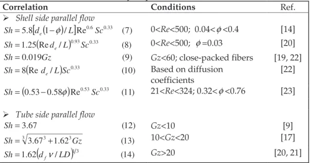
coefficients for hydrophobic hollow fiber modules 28 Table 3.1 Commonly used empirical correlations for calculating heat
transfer coefficient 59
Table 3.2 Values of water activity in NaCl-H2O solutions at different
molality (data at 294K) 68
Table 3.3 MD modules characteristics and membrane properties 69 Table 3.4 Flux and temperature profiles alongside MD020CP2N and
MD080CO2N modules 72
Table 4.1 The main specifications of the membrane modules 99 Table 4.2 Composition of NF retentate and MDC feeds 101 Table 4.3 Operating conditions (simulation only) 101 Table 4.4 Operating conditions using 8 times of NF retentate 102 Table 4.5 Operating conditions using 9 times of NF retentate 104 Table 5.1 The technical operational boundaries of different desalination 115
Table 5.2TheOmani Gulf seawater compositions 122
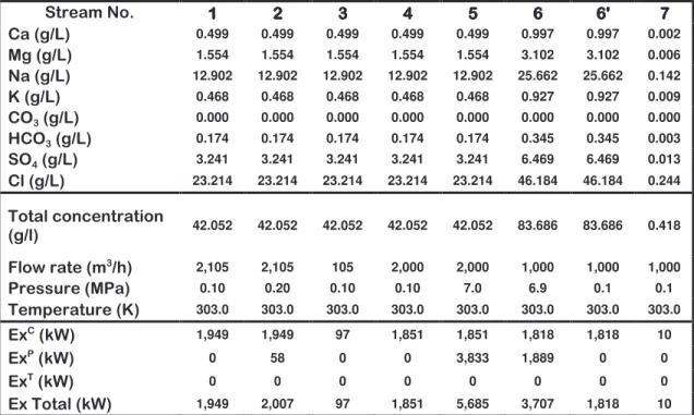
Table 5.3 The composition and the exergy variations calculated for each
stream in the pressure-driven membrane operations (UF-RO) 123 Table 5.4 The composition and the exergy variations calculated for each
stream in pressure-driven membrane operations (UF-RO) with
energy recovery 125
Table 5.5 The composition and the exergy variations calculated for each
stream in the pressure-driven membrane operations (UF-NF-RO) 126 Table 5.6 The composition and the exergy variations calculated for each
stream in pressure-driven membrane operations (UF-NF-RO)
with energy recovery 128
Table 5.7 Summary of exergy analysis for the desalination process using
pressure-driven membrane operations 129
Table 5.8 The composition and the exergy variations calculated for each
stream in MD without heat recovery 131
Table 5.9 The composition and the exergy variations calculated for each
stream in MD with heat recovery 131
Table 5.10 Summary of exergy analysis for MD plants with and without
heat recovery system 134
MC unit operating on the NF concentrate within the integrated system
Table 5.12 The amount of chemicals used and crystallized salts from the
NF concentrated stream 136
Table 5.13 The composition and the exergy calculated for each stream in MD unit with heat recovery operating on the RO brine within
the integrated system 136
Table 5.14 The composition and the exergy variations of each stream in
MC unit operating on the RO brine within the integrated system 137 Table 5.15 The amount of chemicals used and crystallized salts from the
NF concentrated and RO brine streams 138
Table 5.16 The composition and the exergy variations of each stream in MD unit with heat recovery operating on the NF concentrate
within the integrated system 139
Table 5.17 Summary of the exergy analysis calculation for the integrated
membrane system (Seawater) 140
Table 5.18 Summary of the exergy analysis calculation for the integrated
membrane system (Brackish water) 142
Table 5.19 Data and assumptions used in the economical study 143 Table 5.20 Cost estimation of several integrated system configurations
(Seawater) 146
Table 5.21 Cost estimation of several integrated system configurations
(Brackish water) 147
Table 5.22 Estimated water cost for different MD plants 148 Table 6.1 NF and RO membrane element specifications 171 Table 6.2 MD home-made MD/MDC module specifications 173
Table 6.3 Oman Gulf Seawater composition 174
Table 6.4 The chemical composition of the NF concentrate 174 Table 6.5 The chemical composition of the RO brine 177 Table 6.6 The Amantea seawater composition
LIST OF FIGURES
Page
Figure 1.1 Schematic demonstration of the PI 3
Figure 1.2 The DSM vision for the PI 4
Figure 1.3 Comparison of technologies used for waste water treatment 6 Figure 2.1 Reactive transfer of CO2 through GLMC 20
Figure 2.2 Schematic representations of hollow fiber modules 23 Figure 2.3 Mass transfer regions and resistances in hydrophobic GLMC 26 Figure 2.4 Scematic reperesentation of the GLMC modeling 35 Figure 2.5 Flow chart of the computer simulation procedure of the GLMC 36
Figure 2.6 The GLMC experimental apparatus 37
Figure 2.7 Amount of CO2 transfer in GLMC versus feed flow rate 38 Figure 2.8 Amount of CO2 transfer in GLMC versus feed pH 39 Figure 2.9 The pH and amount of CO2 transferred along the GLMC
module 40
Figure 2.10 The distribution of Carbonate species versus pH 41 Figure 2.11The amount of the − −−
3
3 and CO
HCO species after CO2 transfer 41
Figure 2.12 The DLS device 42
Figure 2.13 The particle size of CaCO3 precipitation versus time 43
Figure 3.1 Mass transfer resistances in MD 52
Figure 3.2 Mass transport regions and associated transport mechanisms 54
Figure 3.3 Heat transfer resistances in MD 57
Figure 3.4 Schematic representation of the MD modeling procedure 64 Figure 3.5 The algorithm of the computer simulation for MD 67 Figure 3.6 A scheme of the experimental apparatus 68 Figure 3.7 Cumulative probability distribution versus local packing
fraction for different packing densities 70
Figure 3.8 Effect of the non-uniform packing of fibers on the
fluid-dynamics of different MD modules 71
Figure 3.9 Experimental and simulation results showing the effects of the feed temperature on the MD flux for different membrane
modules 73
Figure 3.10 Simulation results showing the effects of the feed temperature on the thermal efficiency of MD for different membrane
modules 73
Figure 3.11 Experimental and simulation results showing the effects of the
feed flow velocity on the MD flux 74
Figure 3.12 Experimental and simulation results showing the effects of the feed flow velocity on the MD thermal efficiency 75
Figure 3.13 Effect of the solution concentration on the MD performance 76 Figure 3.14 Comparison of the MD and RO flux at different concentration 77 Figure 3.15 Simulation results of the effects of the membrane thermal
conductivity on the MD performance 78
Figure 3.16 Simulation and experimental results of the effects of the
membrane thickness on the MD performance 80
Figure 3.17 Simulation and experimental results of the effects of the
membrane porosity on the MD performance 81
Figure 4.1 Conventional industrial crystallizers 88
Figure 4.2 Membrane crystallizer 89
Figure 4.3 Categories of nucleation 91
Figure 4.4 The Gibbs free energy versus the critical cluster size 93 Figure 4.5 Flow chart of the computer simulation procedure of the batch
crystallizer 98
Figure 4.6Schematic representation of the bench-scale membrane
crystallizer experimental apparatus 100
Figure 4.7 Transmembrane flux and feed concentration versus time 102 Figure 4.8 MDC transmembrane flux and CPC versus time 103
Figure 4.9 Permeate volume versus time 104
Figure 4.10 MDC transmembrane flux and CPC versus time 105
Figure 4.11 Permeate volume versus time 106
Figure 4.12 Crystal size distribution at different time 106 Figure 4.13 Morphology of NaCl crystals (magnification ×10) 107
Figure 5.1 Water situation around the world 112
Figure 5.2 Desalination plants sorted by capacity, technology, feed source
and regions 113
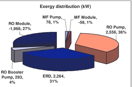
Figure 5.4 The exergy distribution in UF-RO plant without energy
recovery system 123
Figure 5.5 The energy recovery device in UF-RO plant 124 Figure 5.6 The exergy distribution in UF-RO plant with energy recovery
system 125
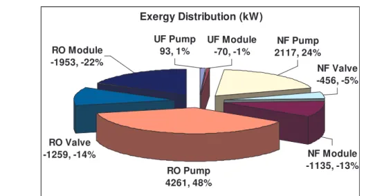
Figure 5.7 Pressure-driven membrane operations (UF-NF-RO) 126 Figure 5.8 The exergy distribution in UF-NF-RO plant without energy
recovery system 127
Figure 5.9 The energy recovery device in UF-NF-RO plant 127 Figure 5.10 The exergy distribution in UF-NF-RO plant with energy
recovery system 127
Figure 5.11 MD without heat recovery 130
Figure 5.12 MD with heat recovery 130
Figure 5.13 The exergy distribution in MD plant without heat recovery
Figure 5.14 The exergy distribution in MD plant with heat recovery system 133
Figure 5.15 UF-NF-RO with MC_NF+MD_RO 135
Figure 5.16 UF-NF-RO with MC_NF+MC_RO 137
Figure 5.17 UF-NF-RO with MD_NF+MD_RO 137
Figure 5.18 Effects of the RO water recovery on the total water cost of
UF-RO plants 149
Figure 5.19 Effects of the RO water recovery on the total water cost of
UF-NF-RO plants 150
Figure 5.20 Effects of the NF water recovery on the total water cost of
UF-NF-RO plants 151
Figure 5.21 Effects of the MD water recovery on the total water cost of MD
plants 152
Figure 5.22 Effects of temperature difference on the product water cost for MD without HR system and for MD with HR system 154 Figure 5.23 Effects of the feed concentration on the total water cost of
UF-RO plants 155
Figure 5.24 Effects of the feed concentration on the total water cost of
UF-NF-RO plants 155
Figure 5.25 Effects of the feed concentration on the total water cost of MD
plants 156
Figure 5.26 Effects of the feed concentration on the total water cost of
UF-NF-RO-MC_NF-MD_RO plants 157
Figure 5.27 Effects of the membrane cost on the total water cost of UF-RO
plants 158
Figure 5.28 Effects of the membrane cost on the total water cost of
UF-NF-RO plants 159
Figure 5.29 Effects of the membrane cost on the total water cost of MD
plants 159
Figure 5.30 Effects of the membrane cost on the total water cost of
UF-NF-RO-MC_NF-MD_RO plants 160
Figure 5.31 Effects of the electricity cost on the total water cost of UF-RO
plants 161
Figure 5.32 Effects of the electricity cost on the total water cost of
UF-NF-RO plants 161
Figure 5.33 Effects of the electricity cost on the total water cost of
UF-NF-RO-MC_NF-MD_RO plants 162
Figure 5.34 Effects of the steam cost on the total water cost of MD plants 163 Figure 5.35 Effects of the steam cost on the total water cost of
UF-NF-RO-MC_NF-MD_RO plants 164
Figure 5.36 Effects of membrane life time on the total water cost of
desalination plants 165
Figure 6.2 The NF/RO plant 171
Figure 6.3 The MD/MDC plant 172
Figure 6.4 Transmembrane flux and feed concentration versus operation
time of MDC operated on the NF retentate 175
Figure 6.5 CDS of the crystals obtained by the MDC operated on NF
retentate 176
Figure 6.6 Transmembrane flux and feed concentration versus operation
time of MDC operated on the RO brine 177
Figure 6.7 CDS of the crystals obtained by the MDC operated on RO brine 178
Figure 6.8 ln(Gr) versus ln(S-1) 179
Figures 6.9 Morphology of the crystals (magnification ×10) 180 Figure 6.10 MD performance in seawater desalination 181 Figure 6.11 Permeate conductivity versus operation time 182
! ! ""## $ $$$ # # %% & &
Summary
This is the first chapter in the thesis which includes some introductory information about the process intensification strategies and benefits. It also shows the importance of membrane science and technology in satisfying the process intensification goals in desalination industry. It ends up by stating the research project objectives and activities.
1.1 Process intensification (PI)
Over the last two decades, different definitions of this term were published. Cross and Ramshaw defined PI as follows: “Process intensification is a term used to describe the strategy of reducing the size of chemical plant needed to achieve a given production objective”[1]. Stankiewicz and Moulijn [2] proposed the following definition: “Process intensification consists of the development of novel apparatuses and techniques that, compared to those commonly used today, are expected to bring dramatic improvements in manufacturing and processing, substantially decreasing equipment-size/production-capacity ratio, energy consumption, or waste production, and ultimately resulting in cheaper, sustainable technologies”. They also provided a description of the PI toolbox which contained two dimensions namely, equipment and processing methods. From business point of view, the BHR Group defined PI as [3]: “Process Intensification (PI) is a revolutionary approach to process and plant design, development and implementation. Providing a chemical process with the precise environment it needs to flourish results in better products, and processes which are safer, cleaner, smaller - and cheaper. PI does not just replace old, inefficient plant with new, intensified equipment. It can challenge business models, opening up opportunities for new patentable products and process chemistry and change to just-in-time or distributed manufacture”.
As realized from the above definitions, PI is the development of innovative apparatuses, techniques and methodologies that offer a drastic improvement in the manufacturing and processing, and substantially increasing
the process efficiency, reducing equipment size and reducing energy consumption, and minimizing the environmental impact by recycling waste, reduce waste formation, reduce hazardous materials and reduce raw material utilization. Ultimately it leads to cheaper, safer and sustainable technique as demonstrated in Figure 1.1.
Figure 1.1 Schematic demonstration of the PI
Apparently, the philosophy of the PI has been characterized by four words: smaller, cheaper, safer and cleaner. The PI leads to substantially cheaper processes particularly in terms of land costs (higher production per unit area), investment costs (compact equipment and integrated processing units which reduce civil work), costs of raw materials (due to higher yields and selectivities), costs of energy (due higher energy efficiency), and costs of waste (less waste generation). Indeed, equipment size, land use costs, and process safety are among the most important PI motivations [4]. In this sense, several years ago DSM published a picture symbolizing its own vision of process intensification
[5], in which skyscraping distillation towers of the naphtha-cracking unit were replaced by a compact, clean, and tidy indoor plant as shown in Figure 1.2.
Figure 1.2 The DSM vision for the PI
Satisfying the increasing demand for raw materials, energy and product under the constraints of sustainable development and environment protection is challenging the chemical and process engineering. However, PI has provided a pathway to maintain sustainability of the chemical and process engineering through the rational integration and implementation of new industrial, economical, environmental and social strategies. PI involves the design of novel equipment based on scientific principles and new production methods which leads to more or less complex technologies that replace conventional equipment or processes with ones that are smaller, cheaper and more efficient; or that combine multiple operations into a single apparatus or into fewer devices [6].
1.2 The role of membrane science and technology in satisfying the PI targets Membrane science and technology is expected to give a substantial contribution to satisfy the process intensification goal to develop substantially pathways, thus providing reliable options for both industrial growth and environmental protection. In fact, membrane technology can be the key factor in
the rationalization of the process intensification due to their characteristics of high efficiency, operational simplicity, high selectivity and permeability for mass transfer of specific compounds, compatibility of different membrane operation to work in an integrated system, low energy requirement, operational stability, environmental compatibility, easy control and scale up and large flexibility [7].
Membrane technology has been applied in many scientific and industrial fields. Essentially, membrane technology succeeded in biochemical applications (such as artificial kidneys and livers, extracorporeal blood oxygenators and dialysis), food processing and water treatment and desalination [8]. This study will mainly focus on the application of membrane technology in the water desalination industry aiming to meet the PI requirements.
1.3 Application of membrane technology and PI in desalination
Desalination processes were developed to obtain fresh water from the earth’s inexhaustible supply of seawater. The two most successful commercial water desalination techniques involve thermal and membrane separation methods. Thermal separation processes include multi stage flash (MSF), multi effect evaporation (MEE) / multi effect distillation (MED), vapor compression (VC) and solar desalination. Membrane separation processes include reverses osmosis (RO) and electro-dialysis (ED). Among these different technologies available, MSF distillation and RO dominate the existing plants [9].
Water shortage problem is now becoming more and more evident worldwide due to the limited water resources and increased population growth. Rational utilization and sustainable water resources management in combination with waste water treatment and developing high efficiency desalination technologies are the only solutions to face water shortage problem [10]. Therefore, desalination is no longer a marginal water resource for municipal and industrial use as in some countries like as Qatar, Saudi Arabia and Kuwait.
Two-third of the world’s desalination plants are located in Gulf Cooperation Council (GCC) countries: Saudi Arabia, Kuwait, Qatar, Bahrain, UAE, and Oman [9].
Currently, reverse osmosis (RO) is one of the most prevalent technologies for seawater desalination. However, a crucial drawback of RO membranes is their weakness against fouling due to the presence of colloidal, particulate, dissolved organics and inorganic matter in feed water, as well as biological growth in the RO system. Therefore, it is required to install a pretreatment step for the feed water before going to the RO unit. The conventional pre-treatment were based on mechanical treatment (media filters, cartridge filters) followed by extensive chemical treatment like flocculation, coagulation, acid treatment and disinfection. The main problems in using the conventional pretreatment is that it does not represent a complete barrier to colloids and suspended particles and produces unsteady feed water quality and quantity [11]. In addition, this pretreatment is known to be complex, labor intensive and space consuming [12]. Furthermore, it consumes large amount of chemicals which are used for coagulant dosages to provide surface charge neutralization, chlorination to limit biological growth, and flocculation-sedimentation sequences. Similar technology used to treat waste water was found 500 years ago in the Agricola’s book De Re Metallica (1556) [7] indicating that the hardware remained unchanged as shown in Figure 1.3.
1.3.1 Integrated pressure-driven membranes system
Integrating the various pressure-driven membrane operations in one system is the first step towards satisfying the PI obligation. In fact, pressure-driven membranes such as microfiltration (MF) and ultrafiltration (UF) are the new trends in designing the pretreatment systems for desalination plants and they can be used as a substitute for the conventional pretreatment technologies. MF can remove suspended solids and lower the silt density index (SDI) while in UF, not only suspended solids and large bacteria are retained, but also (dissolved) macromolecules, colloids and small bacteria. MF and UF pretreatment leaded to a better control of membrane biofouling, increased the membrane lifetime, and limited the cleaning frequency of the plant. Furthermore, permeate fluxes measured at the successive high-pressure membrane filtration unit increase up to 30% [13], thus resulting in higher reliability and better overall economics of the desalination system. In RO desalination, the capital and operating costs are the major drivers for process selection and due to relatively low water recovery in RO plants, any cost saving incurred in the pretreatment system will strongly affect the cost of water produced. Actually, the MF/UF were predicted to contribute for about 10% reductions in the total water cost [13]. It has been reported that a reduction of 39% in the operating and maintenance costs can be achieved when replacing the conventional pretreatment with MF or UF. Besides, the elimination of flocculation, recarbonation, and filtration steps will decrease the power and chemical costs and reduce the plant space which leads to a significant reduction in the plant capital costs [14].
.
Moreover, nanofiltration (NF) is today used in softening, disinfection, and removal of organic materials and metals. The installation of NF as a pretreatment will lead to a breakthrough in the application of RO due to its capability of effectively removing dissolved organic compounds, scale forming hardness ions, and bivalent ions. As consequence, the osmotic pressure of RO
feed and retentate streams is decreased, thus allowing the system to operate at high water recovery factors (70%) with minor scaling problems [15].
At this stage, the integrated pressure-driven membrane (MF/UF-NF-RO) system is characterized by global water recovery factors up to 50%, energy saving of 25-30%, less consumption of chemicals and additives, smaller land space, and less amount of discharged wastes[16, 17].
Despite the fact that the utilization of RO in combination with other pressure-driven membrane operations such as MF, UF and NF has led fundamental contribution in terms of overall process economics, some critical developments are still necessary in order to accomplish possible improvements in the process efficiency (increase recovery), operational stability (reduce fouling and scaling problems), environmental impact (reduce brine disposal), water quality (remove harmful substances) and costs. In particular, cost effective and environmentally sensitive concentrate management is today recognized as a significant obstacle to extensive implementation of desalination technologies. Considering a typical RO desalination plant with water recovery factor of 45– 60% (seawater) or 75–85% (brackish water), this would result in a significant excess of high concentrated solutions to be disposed-off. At present, the most frequent disposal practice for brines is a direct discharge into lakes, lagoons, rivers, ocean and sanitary drains. However, the requirements of more and more rigid environmental protection regulations will stop this low-cost brine disposal in the near future [18].
As a result of the significant impact of desalination plants on the environment, the requirements for concentrate management tight up: brine disposal minimization and zero liquid discharge (ZLD) are the demanding targets for several applications. In the last years, several process engineering strategies have been implemented in order to accomplish the concept of the ZLD in seawater desalination [19].
1.3.2 Innovative membrane contactors technology and their potential of integration
Gas-liquid membrane contactors (GLMC) are an emerging technology in which the hollow fiber porous membranes are used as a tool for inter-phase mass transfer. They are able to immobilize the gas-liquid interface at the membrane pores due to the hydrophobic nature of the membrane itself, and to create a large contact area that activates stripping or absorption processes. The surface/volume ratio in membrane hollow fibers is one order of magnitude higher than the conventional separators and therefore GLMC offers additional advantages of higher liquid mass transfer coefficients, simple and flexible design procedures, and the nonexistence of fluid dynamic limitations (flooding) [20]. GLMC allows an adequate control of dissolved gas composition against corrosion and depletion of the water quality. Moreover, the reactive transfer of CO2 allows to
control the simultaneous precipitation equilibrium of inorganic salts, acting on the pH of the solution [21]. Hence, the GLMC’s are employed as pretreatment to prevent scaling and as post-treatment to improve the water quality.
Membrane distillation/crystallization (MD/MC) is a well-known methodology having great potential as evaporation process carried out at relatively low temperature by using microporous hydrophobic membranes. The hydrophobic nature of the membrane prevents the mass transfer of the liquid phase and creates a vapour-liquid interface at the pore entrance. Here, volatile compounds evaporate, diffuse and/or convect across the membrane pores, and are condensed and/or removed on the opposite side (permeate or distillate) of the system. The driving force is the partial pressure difference created by the temperature difference between the two phases which allows theoretically the complete rejection of non-volatile solutes. Lower temperatures and pressures with respect to those usually used in conventional distillation columns are generally sufficient to establish a quite interesting transmembrane flux (1-20
kg/m2h), with consequent reduction of energy costs and mechanical
requirements of the membranes [22]. Typical feed temperatures vary in the range of 30-60 °C, thus permitting the efficient recycle of low-grade or waste heat streams, as well as the use of alternative energy sources (solar, wind or geothermal). In addition, the possibility to use plastic equipments also reduces or avoids corrosion problems. If compared with RO, MD does not suffer limitations arising from concentration polarization phenomenon and can be preferentially employed whenever high permeate recovery factors are requested [22]. MD is characterized by production of high purity distillate, reduced sensitivity to fouling and absence of concentration polarization phenomena, and high flexibility.
Membrane crystallization (MC) has been recently proposed as one of the most interesting and promising extension of the MD concept in which solutions are concentrated above their saturation limit and achieve a metastable state (supersaturation) in which crystals nucleate and grow [23]. MC, therefore, represent an additional option for realizing integrated membrane desalination systems.
MD/MC units also offer the attractive opportunity to be integrated in water treatment cycles. In this respect, an MD unit, operating on the brine of a RO plant, allows to reach higher recovery factor in a seawater desalination application with respect to a single RO stage. Drioli et al. [24] obtained a total fresh water factor recovery of about 88% (40% for the RO unit and 77% for the MD stage) by operating an MD unit on the retentate of a SWRO plant with a considerable reduction in the quantity of brine produced. Additionally, the use of MC allows the recovery of NaCl and MgSO4.7H2O from brines. The overall water recovery of the integrated system can be increased up to values approaching 95% [25]. GLMC is employed in order to promote reactive transfer of CO2 into the concentrate stream and to control the ionic strength during
There are some very interesting opportunities to integrate different membrane operations into industrial processes and so achieve the overall benefits of PI. In this context, the combination of the conventional pressure-driven membrane operations such as MF, NF and RO with the membrane contactors technology such as gas-liquid membrane contactors (GLMC) and membrane distillation/crystallization processes (MD/MC) is expected to offer alternative design-pathways for improving water quality and brine management. The integration of different membrane units will fulfil the PI strategy and will represent an interesting way for achieving the ZLD goal due to the possibility of overcoming the limits of the single units and, thus, to improve the performance of the overall operation [26].
Although the combination of two or more conventional unit operations within one framework permits a high possibility of energy savings and/or capital investment reduction, it never means that the full potentials can be simply achieved with an arbitrary combination of all the conventional unit operations considered. It might lead to more challenging problem in process operation than the conventional design philosophy due to the intensified internal mass and energy integration. Hence, a matter of serious concern in process intensification is the occurrence of complicated process dynamics and the introduction of great difficulties to process operation. Consequently, it is required to identify the process dynamics and operation at early stage of the process development in order to avoid such problems. In addition, it should be indicated that the way to combine all the conventional unit operations involved could actually have a strong effect upon the process dynamics and controllability. Due to the strong interactions between internal mass integration and energy integration, a careful trade-off has to be implemented in process development [27].
1.4 Objectives
The primary objective of this research is to study the combination of the membrane contactors technology with the pressure driven membranes in order to completely redesign the water desalination plants. The research project focuses on the elaboration of an innovative technological approach in order to:
• Improve the efficiency of membrane desalination systems by combining the single membrane units in a globally optimized and compact integrated membrane desalination system and processing NF/RO retentate by MD/MC units in order to increase the overall recovery factor (up to 95%) and to decrease the concentrated wastes.
• Produce water with good quality by remove a wider range of contaminants (including boron) by using evaporative membrane units able to reach 100% retention of solutes, colloids, non-volatile organic contaminants etc.
• Keep water affordable by decrease operating costs.
• Ensure sustainability of desalination plants by facing the brine disposal problem through processing superconcentrated streams in order to produce crystalline salts with high purity, controlled shape and crystal size distribution.
1.5 Project description
This research program will consider: (i) a theoretical part aiming to develop appropriate tools for the analysis and simulation of membrane contactors units and for predicting the effects of the main operative parameters on the performance of the single stage; (ii) an energy and exergy analysis of the integrated membrane desalination system for process optimization and diagnosis of inefficiencies; (iii) a cost analysis for evaluating the potential economics; (iv) an experimental phase, to carry out in parallel with the modelling activity, aiming to
confirm the reliability of the proposed approach; (v) the realization of a bench-scale integrated membrane desalination plant.
The project work is subdivided into the following tasks:
TASK 1. Modeling and optimization of the integrated membrane system
This study will be mainly on the modeling and optimization of the GLMC and the MD/MC units.
Task 1.1: Analysis and simulation of a GLMC unit
Research activities:
• Investigation of main process variables (temperature, pressure, gas and liquid flow rates, pH, structural properties of the membrane) on the gas transfer rate.
• Identification of the controlling resistance to mass the transport and optimization of the GLMC unit.
Task 1.2: Analysis and simulation of MD/MC units
Research activities:
• Solving mass and heat balances in order to predict the transmembrane flux as function of the operative variables and to control polarization phenomena.
• Identifying the fluid-dynamic threshold representing the transition from a regime with low diffusion rate to a regime with higher relative weight of interfacial kinetics, in order to limit the potential effect of impurity.
• Predicting crystal size distribution (CSD) according to Population-Balance equations and to characterize its dispersion value by the Coefficient of Variation (CV).
TASK 2. Energy and exergy analysis of the integrated membrane system
A comprehensive analysis based on the second law of thermodynamics will be carried out by considering entropy production, thermal, electrical and mechanical inputs to the integrated schemes. A literature survey will allow determining and/or updating substitution coefficient, energy sources conversion and efficiency. Inefficiency in integrated processes due to their intrinsic irreversibility will be identified, located and quantified in order to elaborate possible strategies for improving locally and globally the system design.
Energy and exergy analysis aims to compare the potentialities and performance of different integrated schemes in terms of energy demand and exergy efficiency. This analysis will represent a crucial tool for selecting the optimal schemes in order to realize a final prototype of integrated plant and successive adjustments of the operative conditions.
TASK 3. Cost analysis and sensitivity study of the integrated membrane system In order to estimate the economic feasibility of the proposed integrated system, a cost analysis will be also carried out.
The economic evaluation will consider:
- The impact of additional membrane contactor units on the installation and operating costs as a result of an increased consumption of electric power, heating steam for thermally driven membrane operations (membrane distillation/crystallization), chemicals, membranes and maintenance.
- Influence of the increased water recovery ratio on the unit product cost.
- Potential economics of crystalline salts produced by membrane crystallization from brine.
A sensitivity study will investigate the effect of changing a single variable on the integrated system with the aim to optimize the process profitability. The major
operational parameters will be identified and related to the overall system performance.
TASK 4. Experimental tests on membrane contactor units
The experimental study will be carried out on GLMC and MD/MC units.
Task 4.1 Experimental tests on Gas-Liquid Membrane Contactor unit
The activities will focus on the study of CO2 transfer from the liquid phase to the
gas phase
Task 4.2 Experimental tests on Membrane Distillation/Crystallization unit
The experimental study on MD will consider the evaluation of distillate fluxes at different transmembrane temperatures and flow rates, the study of polarization phenomena and their detrimental effect on the overall efficiency of the unit, the stability of the hydrophobic character of the membrane in long-term operations, the water recovery factor. Experiments on MC will be devoted to identify the favorable operative conditions for obtaining a crystalline product with uniform size distribution and high purity, combined with appropriate quality of the water permeate and higher recovery factors approaching 90-95%.
The experimental activity will focus on:
• Study of the evaporation efficiency as function of energy input and trans-membrane flux of permeate. Optimization of the operative conditions and targets (transmembrane temperatures feed and permeate flow rates, longitudinal pressure drop, brine concentration and recovery factor). • Evaluation of the stability (preservation of hydrophobic property) of
MD/MC membrane modules against fouling, plugging, and caking.
• Analysis of the crystalline product in terms of shape, purity, crystal size distributions and yield.
TASK 5. Running a semi-pilot prototype of integrated membrane desalination system
The final goal is to integrate the various membrane operations, starting from UF-NF as pre-treatment for RO and membrane contactors devices in opportune configuration, and to define the strategies and protocols requested to operate the system at high recovery factors (>95%), for inducing selective formation of crystals from high concentrated brine with improved characteristics in terms of shape and size distribution.
1.6 Potential for practical applications
This project will significantly contribute to a better quality of produced water by enhancing the rejection properties of the membrane desalination system as result of the use of MD unit in the integrated process. In addition, the amount of rejected brine will be decreased which will help in maintaining the sustainability of the desalination plant. The synergic use of MD/MC units on the NF and RO retentate will offer the possibility to obtain additional fresh water with target recoveries >95%, as well as high-quality crystals (NaCl, MgSO4*7H2O) for successive applications. Keeping water affordable is a
consequential purpose of the research project. It is well recognized that driving down the cost of water produced from next-generation desalination technologies will require a dedicated research and development program that focuses on:
• Increasing production efficiency, that involves improving the quantity of water produced per unit of energy consumed.
• Reducing costs.
The innovative concepts and design of integrated desalination schemes are expected to match the PI strategies leading to cheaper, safer and sustainable technique.
REFERENCES
[1] W.T. Cross, C. Ramshaw, Chem. Eng. Res. Des., 64 (1986) 293.
[2] A.I. Stankiewicz, J.A. Moulijn, Process intensification: Transforming chemical engineering, Chemical Engineering Progress, 96 (2000) 22.
[3] http://www.bhrgroup.co.uk/pi/aboutpi.htm.
[4] A.I. Stankiewicz, J.A. Moulijn, Re-engineering the chemical process plant: Process Intensification, Marcel Dekker Inc., New York (2004).
[5] Sustainable Technological Development at DSM: The Future Is Now, DSM Magazine, 83 (1999) 4.
[6] J.C. Charpentier, In the frame of globalization and sustainability, process intensification, a path to the future of chemical and process engineering (molecules into money), Chemical Engineering Journal 134 (2007) 84.
[7] E. Drioli, E. Curcio, Membrane engineering for process intensification: a prospective, Journal of Chemical Technology and Biotechnology 82 (2007) 223.
[8] S. Al-Obaidani, Chemical cleaning of micro-filtration membranes used for pretreatment of oil contaminated seawater, M.Sc. thesis (2004).
[9] IDA Desalination Year book 2007-2008, Water desalination report, (2008). [10] E. El-Zanati, K.M. El-Khatib, Integrated membrane – based desalination
system, Desalination 205 (2007) 15.
[11] A. Brehant et al., Comparison of MF/UF pretreatment with conventional filtration prior to RO membranes for surface seawater desalination, Desalination 144 (2002) 353.
[12] S van Hoop, J.G. Minnery and B. Mack, Dead-end ultrafiltration as alternative pre-treatment to reverse osmosis in seawater desalination: a case study, Desalination, 139 (2001) 161.
[13] M. Wilf and M.K. Schierach, Improved performance and cost reduction of RO sweater systems using UF pretreatment, Desalination, 135 (2001) 61. [14] G.L. Leslie et al., Proc. AWWA, Water Reuse Conference, Florida (1998). [15] N. Hilal et al., A comprehensive review of nanofiltration membranes:
Treatment, pretreatment, modeling, and atomic force microscopy, Desalination 170 (2004) 281.
[16] M.M. Nederlof, J.C. Kruithof, J.S. Taylor, D. van der Kooij and J.C. Schippers, Comparison of NF/RO membrane performance in integrated membrane systems, Desalination, 131 (2000) 257.
[17] E. Drioli, A. Criscuoli, E. Curcio, Integrated membrane operations for seawater desalination, Desalination 147 (2002) 77.
[18] E. Drioli et al., integrating membrane contactors technology and pressure-driven membrane operations for seawater desalination energy, exergy and costs analysis, Chemical Engineering Research and Design, 84 (A3) (2006) 209.
[19] A. Seigworth, R. Ludlum, E. Reahl, Case study: Integrating membrane processes with evaporation to achieve economical zero liquid discharge at the Doswell combined cycle facility, Desalination 102 (1995) 81.
[20] E. Drioli E, A. Criscuoli A, E. Curcio, Membrane Contactors: Fundamentals, Applications and Potentialities. Elsevier, Amsterdam (2006).
[21] Gabelman, A. and S.T. Hwang, Hollow fiber membrane contactors, Journal of Membrane Science 159 (1999) 61.
[22] K. W. Lawson and D. R. Lloyd, Review: Membrane distillation, Journal of Membrane Science 124 (1997) 1.
[23] E. Curcio, A. Criscuoli, E. Drioli, Membrane crystallizers, Ind. Eng. Chem. Res. 40 (2001) 2679.
[24] E. Drioli, F. Laganà, A. Criscuoli, G. Barbieri, Integrated membrane operations in desalination processes Desalination 122 (1999) 141.
[25] E. Drioli, E. Curcio, A. Criscuoli, and G. Di Profio, Integrated system for recovery of CaCO3, NaCl and MgSO4.7H2O from nanofiltration retentate,
Journal of Membrane Science, 239 (2004) 27.
[26] E. Drioli, E. Curcio and G. Di Profio, State of the art and recent progresses in membrane contactors, ChERD J, 83 (2005) 223.
[27] K. Huang, S.J. Wang, L. Shan, Q. Zhu, J. Qian, Separation and Purification Technology 57 (2007) 111.
SUMMARY
This chapter is dealing with the optimization of the GLMC. It provides the theoretical background necessary for modeling and simulation. It also covers the experimental parts related to the utilization of the GLMC in the proposed integrated membrane system. Finally, it provides a feasibility study to verify the economics of using such devices in the integrated membrane system.
2.1 Objectives
The preliminary objective of using Gas-Liquid Membrane Contactors (GLMC) in the proposed integrated membrane system is to establish a reactive transfer of carbon dioxide (CO2) into sodium hydroxide (NaOH) solutions to produce sodium carbonate (Na2CO3) solution as shown in Figure 2.1. Then
Na2CO3 is used to limit calcium sulphate (CaSO4) precipitation that causes the reduction of sulphate ( 2 )
4−
SO content in the solution and drastically limits the recovery of magnesium sulphate (MgSO4) from the NF retentate stream. Moreover, CO2 is the largest contributor to greenhouse effect and its efficient recovery might also reduce the environmental impacts due to atmospheric emissions in power plants (CO2 represents the 10-13% of stack gas) [1].
2.2 Introduction
Gas-Liquid Membrane Contactors (GLMC) are devices that achieve gas/liquid mass transfer without dispersion of one phase with the other. They are based on a technology in which porous membranes are used as tools for inter-phase mass transfer. However, the membrane does not act as a selective barrier, but the separation is based on the principles of phase equilibrium. This is established by passing the fluids on opposite sides of the microporous membrane. One of the fluids is immobilized in the pores of the membrane so that the fluid/fluid interface is located at the entrance of each pore due to the hydrophobic nature of the membrane itself that creates a large contact area which activates stripping or absorption processes [2]. In gas-liquid mass transfer, a generic species moves from a phase to the other across a microporous hydrophobic membrane under a partial pressure gradient. For example, dissolved oxygen can be removed from water by stripping with carbon dioxide
(CO2), while CO2 is absorbed simultaneously in water [3].
The performances of GLMC strongly depend on the properties of the membranes used. In general, high hydrophobicity is required in order to prevent wetting and mixing between contacting phases; elevated porosity leads to high fluxes, but might cause bubble coalescence [4].
The gas/liquid contacting operation is conventionally carried out in direct contact equipment such as packed or bubble columns [5]. GLMC can be used as a substitute for these conventional equipments due to the following advantages:
• Operational flexibility. The two phases flow independently on each other
since they flow on the opposite sides of the hollow fiber (i.e. shell and lumen) and thus they can be manipulated separately. This is effective for avoiding problems such as flooding, unloading, foaming, channeling and entrainments which are often encountered in packed/tray columns [2].


![Table 3.1 Commonly used empirical correlations for calculating heat transfer coefficient Correlation Reference [25] [38] [37] [26] [39] )15(21pfTTTTTPC−−=)17(,04.01067.066.32/3LkCmGzGzGzNuTP•=++=(Pr) ( )/,1010(18)20.01/41/94<<5=GzlLGzNu()[Re](https://thumb-eu.123doks.com/thumbv2/123dokorg/2881724.10386/77.918.128.789.694.1031/correlations-calculating-coefficient-correlation-reference-pftttttpc-lkcmgzgzgznutp-gzllgznu.webp)
![Figure 5.2 Desalination plants sorted by capacity, technology, feed source and regions [5]](https://thumb-eu.123doks.com/thumbv2/123dokorg/2881724.10386/131.918.137.784.402.819/figure-desalination-plants-sorted-capacity-technology-source-regions.webp)