U
NIVERSITY OF
G
ENOVA AND
ISTITUTO ITALIANO DI TECNOLOGIA
PHD PROGRAM IN BIOENGINEERING AND ROBOTICS
CURRICULUM IN COGNITIVE ROBOTICS, INTERACTION AND
REHABILITATION TECHNOLOGIES
How do humans mediate with the external physical
world? From perception to control of articulated
objects.
by Qinqi XuThesis submitted for the degree of Doctor of Philosophy (31st cycle)
April 2019
Prof. Gabriel Baud-Bovy Supervisor
Dr. Monica Gori Supervisor
Name Head of the PhD program
Abstract
Many actions in our daily life involve operation with articulated tools. Despite the ubiquity of articulated objects in daily life, human ability in perceiving the properties and control of articulated objects has been merely studied.
Articulated objects are composed of links and revolute or prismatic joints. Moving one part of the linkage results in the movement of the other ones. Reaching a position with the tip of a tool requires adapting the motor commands to the change of position of the end-effector different from the action of reaching the same position with the hand. The dynamic properties are complex and variant in the movement of articulated bodies. For instance, apparent mass, a quantity that measures the dynamic interaction of the articulated object, varies as a function of the changes in configuration. An actuated articulated system can generate a static, but position-dependent force field with constant torques about joints. There are evidences that internal models are involved in the perception and control of tools. In the present work, we aim to investigate several aspects of the perception and control of articulated objects and address two questions, The first question is how people perceive the kinematic and dynamic properties in the haptic interaction with articulated objects? And the second question is what effect has seeing the tool on the planning and execution of reaching movements with a complex tool? Does the visual representation of mechanism structures help in the reaching movement and how?
To address these questions, 3D printed physical articulated objects and robotic systems have been designed and developed for the psychophysical studies. The present work involves three studies in different aspects of perception and control of articulated objects. We first did haptic size discrimination tasks using three different types of objects, namely, wooden boxes, actuated apparatus with two movable flat surfaces, and large-size pliers, in unimanual, bimanual grounded and bimanual free conditions. We found bimanual
integration occurred in particular in the free manipulation of objects. The second study was on the visuo-motor reaching with complex tools. We found that seeing the mechanism of the tool, even briefly at the beginning of the trial, improved the reaching performance. The last study was about force perception, evidences showed that people could take use of the force field at the end-effector to induce the torque about the joints generated by the articulated system.
Acknowledgement
I would like to express my great gratitude to my supervisors Prof. Gabriel Boud-Bovy and Dr. Monica Gori for their kind guidance and support during the three years. I would like to thank Prof. Gabriel Baud-Bovy for his precious advices and guidance on my scientific research and technical skills development. I would also like to thank Prof. Eli Brenner and his colleges, for hosting me during my secondment at VU Amsterdam.
I would like to thank Diego Torazza, Andrea Merello, Claudio Lorini, Gaia Risso for their collaboration and contribution to this work.
A special thanks goes to the past and present researchers working on the 4th floor of IIT Morego and fellows around the 7th floor of IIT Erzelli, Genova, for making me integrated to the big family; to people from Human movement sciences department at VU
Amsterdam, for their kind welcome and the good memories during my stay in Amsterdam. I would like to thank the members of PACE network, for organizing the events and
offering trainings in various aspects of the relative fields. I'm grateful to grow together with early stage researchers.
My deepest gratitude goes to my husband and my parents, for their consistent support and encouragement.
Table of contents
Chapter 1: Introduction ... 1
1.1 Sensory transformations and representations in reaching ... 2
1.2 Internal models and control schemes ... 4
1.2.1 Feedforward control ... 5
1.2.2 Feedback control ... 6
1.2.3 Forward model and predictive control ... 7
1.2.4 Forward model in perception... 10
1.3 Haptic perception and the body schema ... 11
1.4 Tool use ... 13
1.4.1 Neuronal bases of tool use ... 14
1.5 Articulated objects ... 15
1.6 Thesis outlines ... 17
Chapter 2: Study one ... 20
2.1 Background ... 20
2.1.1 Early work on multi-modal integration ... 21
2.1.2 Optimal (Bayesian) integration ... 21
2.1.3 The haptic sense and sensory integration within a sensory modality ... 22
2.1.4 Bimanual integration ... 23
2.1.5 Object grounding and the unity assumption ... 24
2.2 Experiment 1: box size discrimination ... 25
2.2.1 Methods ... 25
2.2.2 Data analysis... 27
2.2.3 Results ... 28
2.2.4 Discussion ... 29
2.3 Experiment 2: distance discrimination of flat surfaces ... 31
2.3.1 Methods ... 31
2.3.2 Results ... 32
2.3.3 Discussion ... 33
2.4.1 Methods ... 34
2.4.2 Data analysis... 38
2.4.3 Results ... 38
2.4.4 Discussion ... 41
2.5 General discussion ... 43
2.5.1 Experimental factors that influence bimanual integration ... 44
2.5.2 Bimanual integration in current accounts of sensory integration ... 47
Appendix A ... 51
Chapter 3: Study two ... 53
3.1 Introduction ... 53
3.3 Experiment one... 58
3.3.1 Method... 58
3.3.2 Results and discussion ... 63
3.4 Experiment two and three ... 65
3.4.1 Methods ... 66
3.4.2 Results ... 68
3.5 Visuo-motor rotation ... 70
3.6 General discussion ... 71
Chapter 4: Study three ... 78
4.1 Background ... 78
4.1.1 Point mass... 78
4.1.2 Rigid bodies ... 79
4.1.3 Deformable objects ... 81
4.1.4 Actuated articulated objects ... 81
4.2 Section one - Mathematical modelling ... 82
4.2.1 Static mapping ... 82
4.2.2 Dynamic modelling ... 83
4.3 Section two- System design and development ... 86
4.3.1 Objective ... 86
4.3.2 Design specification ... 86
4.3.3 System characterization ... 87
4.3.4 System development ... 88
4.4.1 Procedure ... 92
4.4.2 Results ... 93
4.4.3 Discussion ... 94
Appendix B ... 96
Chapter 5: General conclusions and recommendations for future work ... 100
5.1 General conclusions ... 100
5.2 Future work ... 102
List of figures
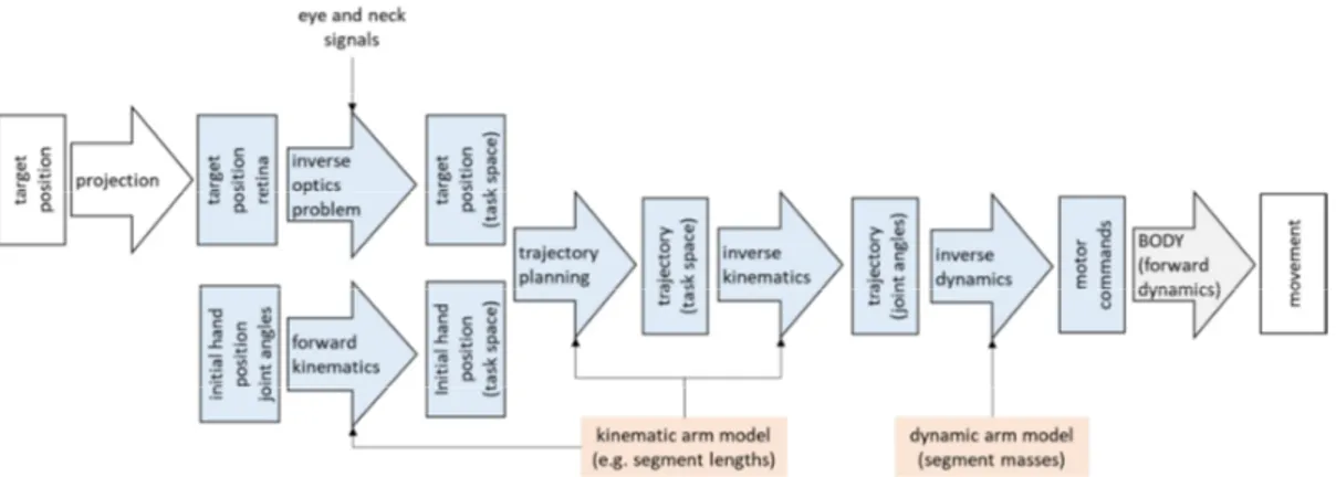
Figure 1. Schematic representation of early transformations involved in the planning and execution
of a reaching motion.. ... 2
Figure 2. Fundamental element of control system ... 5
Figure 3. Feedforward control.. ... 5
Figure 4. Example of feedback control.. ... 6
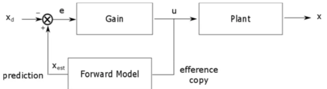
Figure 5. Example of predictive control. ... 7
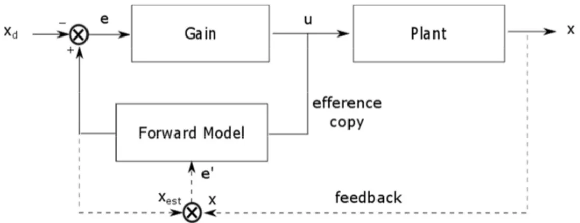
Figure 6. Motor learning. ... 8
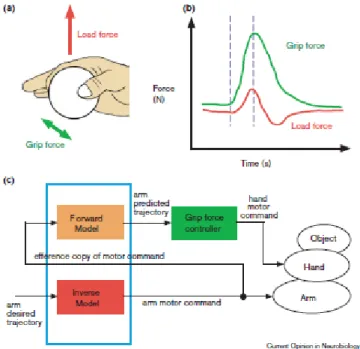
Figure 7. Coordination of grip force and load force, and a computational model based on internal forward and inverse models (Kawato, 1999). ... 9
Figure 8. Sensory cancellation. ... 10
Figure 9. A model of somatoperceptual information processing, highlighting the role of body representations in the construction of somatic percepts. ... 12
Figure 10. Change of posture required to reach the same position in space with a stick. ... 13
Figure 11. Examples of linkages. (Slocum, 2008; 2017 CCCME; kisspng.com). ... 16
Figure 12. Outline of the thesis ... 18
Figure 13. The figure represents a blindfolded participant haptically interacting with a wooden box in the four experimental conditions. ... 26
Figure 14. Results of the box size discrimination experiment. ... 28
Figure 15. Discrimination of distance between flat surface experimental setup.. ... 31
Figure 16. Results of the distance discrimination experiment with flat surfaces. ... 32
Figure 17. Plier size discrimination experimental conditions and stimulus properties. ... 35
Figure 18. Results of the plier size discrimination experiment. ... 39
Figure 19. Computational models in human behavior in the plier manipulation. ... 52
Figure 20. Visuo-motor reaching experimental setup.. ... 59
Figure 21. Mechanisms presented in the first experiment. ... 61
Figure 22. Number of targeted reached across tools and visual conditions.. ... 63
Figure 23. Mechanisms presented in the second and third experiments. ... 67
Figure 24. Effect of mechanism configuration and visual representation on the performance. ... 68
Figure 25. Results for the parallelogram linkages in the three experiments. ... 70
Figure 26. Effect of rotational angles on the performance ... 71
Figure 27. Three groups of force vectors at selected grid of location sites about the corresponding actuated shoulder joint, elbow joint, both joints motor-generated torque. ... 83
Figure 29. First prototype of the modular system ... 88
Figure 30. Components estimation on the interaction torque. ... 90
Figure 31. Current development of the 2DoF system ... 91
Figure 32. Comparison in the produced force in three conditions ... 94
Figure 33. 2-DoF mechanism in local Cartesian coordinates. ... 96
List of Tables
Table 1. Summary of experimental conditions for the three groups ... 36 Table 2. Thresholds expressed in four cues... 40 Table 3. Summary of the principal experiments on bimanual integration. ... 44 Table 4. Specific requirements on the robotic system development in the domain of
psychophysical studies ... 86 Table 5. Responses from six subjects ... 93
1.1 Sensory transformations and representations in reaching 1
Chapter 1
Introduction
Many actions in our daily life, such as opening a door, using wine openers, playing musical instruments (e.g. a trombone) and operating forceps in surgery, involve interaction with articulated (kinematically-constrained) tools. In the field of robotics, it has long been recognized that tool interaction is particularly challenging as it requires one to reach the kinematic and dynamical levels of control simultaneously. Depending on the
circumstances, these actions can be done with various degrees of precision. In the present work, the objective is to investigate how human perceives the kinematic and dynamic properties in the control of articulated objects.
The capability of using tools is a remarkable milestone in human evolution history. The use and development of even more sophisticated tools has been and still is a motor of human progress. Archaeological records of tool use in human evolution tracks back to 3.3 million years ago, when hominin fossils and stone tools were found in Africa regions (Toth & Schick, 2015). Observations show that chimpanzees, one of mankind closest primate relatives, use of sticks for ant dipping. In particular, chimpanzees can hold a stick with one hand and dip it among the soldier ants at the nest entrance in order to fish them. Chimpanzees are also able to learn to use tools to solve trap problems and make their own tools (Seed, Call, Emery, & Clayton, 2009). For example they can intentionally set out a nutcracker by breaking a branch to get access to food (Boesch & Boesch, 1990).
Although several species are considered to possess tool-use skills, including mammals, birds, fish, cephalopods and insects, the way human makes and uses complex tools is perhaps the ability that sets our species apart more than anything else. Tools are serving as important mediators between our internal cognitive world and the external physical world. As a matter of facts, skilled tool-use combines multi-sensory perception, cognitive modelling and manual dexterity. It has often been viewed as a sign of higher cognitive ability, or even as the hallmark of the evolution of human intelligence as a more productive way to accomplish daily activities (Osiurak & Massen, 2014; van Schaik, Deaner, & Merrill, 1999; Wynn, 1985). So a fundamental issue is what are the cognitive and sensory-motor basis of human tool use?
1.1 Sensory transformations and representations in reaching 2
The general objective of this thesis is to shed light on the psychophysical aspects in haptic perception and control of articulated tools. Despite its ubiquity in everyday action, human ability in tool-use with articulated objects has been rarely studied. The interested questions involve whether and how our brain integrates information about the geometrical properties of articulated object from two hands in order to build internal model; and investigate the possible ways with which internal representation is developed, that is, the contribution from different sensory inputs (for instance, haptic and visual sensory feedback) in the perception or control of articulated tools.
In this introduction, we review concepts that are important to understand sensorimotor processes involved in the perception and control of action, from simple reaching movement to tool-use.
1.1 Sensory transformations and representations in reaching
Figure 1. Schematic representation of early transformations involved in the planning and execution of a reaching motion. The blue squares represent signals/representations in the nervous system while the blue arrows represent transformations between these representations. The orange squares represent information about the body (internal models) needed by the transformations.
Motor control, from planning an action to its execution, involves a series of
transformations. Taking a simple reaching movement as an example, a first transformation happens when acquiring information about the position of the object (or target) in the environment. This transformation involves the projection of the 3D position of the object on the retina, a 2D representation. Planning and executing the reaching movement also
1.1 Sensory transformations and representations in reaching 3
involve computing the motor commands that will move the hand position from its initial position to the object. This process can be quite complex and various control schemes have been proposed to achieve this objective (e.g. see Feldman & Levin, 2009; Latash, 2010) in an alternative viewpoint. An useful idea inspired by engineering consists in decomposing this process into a series of transformation that involves (i) planning the hand movement, (ii) computing the joint angles (arm posture) that corresponds to hand position, and (iii) computing the joint torque and muscle activities necessary to move the hand and arm along the desired trajectory (Atkeson, 1989).
An important observation about human movement in the 2D space is that the hand trajectory tend to be straight, which suggest the trajectory is planned in the Cartesian (task) space (Morasso, 1981). It is important to note that a complex (non-linear) coordination of the shoulder and elbow joints as well as a compensation of interaction torque (dynamic effects) are needed to produce a straight trajectory (Gribble & Ostry, 1999). According to the schema presented in Figure 1, two sensory transformations are needed to plan a movement in the Cartesian space. First, it is necessary to transform the retinal (2D) target representation into a 3D body centered representation (Vindras & Viviani, 1998). This transformation requires knowing the position of the eye and head and computing the distance of the target from the body, an instance of inverse problem for vision (Pizlo, 2001). Second, it is also necessary to know the initial position of the hand in the same 3D space (Baud-Bovy & Viviani, 1998). The transformation of proprioceptive signals coming from sensory afferents (spindles) in the muscles into a 3D representation corresponds to the forward kinematics transformation from joint angles (indirectly coded by muscle lengths) into the 3D position of the end-effector (the hand) in robotics. Then, once the trajectory has been planned in the Cartesian space, two additional transformations are necessary to compute the motor commands. The first transformation, which corresponds to the inverse kinematics transformation in robotics, transforms the hand position into the joint angles. Finally, the joint angles must be transformed into a set of joint torques and motor commands that move the robot along the desired trajectory according to the inverse dynamics transformation of the robotic configuration.
Several of these transformations involve a change of reference frames used to represent spatial information (McGuire & Sabes, 2009; Soechting, 1992). For example, target position is initially represented in 2D eye-fixed reference frame and then
1.2 Internal models and control schemes 4
successively transformed in a body-centered reference frame and finally in a joint space representation. This schema, while oversimplified with respect to reality, illustrates the fact that the same information can be represented in multiple ways in the brain. It also suggests that representations are closely linked to the processes that connect them and to the goal of the action (Grush, 1997). Moreover, specific computation can take place within a representation or reference frame. For example, trajectory planning is thought to be happen within a Cartesian reference frame (Tamar, Meirovitch, & Barliya, 2013; Morasso, 1981). According to Hubbard (2007), structures, processes, and mappings are the three key elements of a representation. Structure refers to the parts of the model at each level, properties of these structures varying from level to level; process is what and how information is used within a structure; and mapping involves a connection between structures. Cunningham (1989) proposed a method to discover the sensorimotor
transformations and representations by the central nervous system by studying errors that occur when the natural mapping between sensory signals and motor commands is
artificially transformed by wearing prisms or using a tool for example.
Besides of the information about the target and hand positions in space, it should be noted that the kinematic and dynamic transformations needed to plan and/or execute the movement requires also information about the whole body. For example, solving the inverse kinematics problem requires the structure of the arm and the length of its segments. Similarly, computing in advance of the joint torque to bring the hand to the target requires taking into account the dynamic properties of the body such as the masses of the arm and forearms. Altogether, these information form the so-called internal models of the body, which play a central role in modern accounts of how movements are controlled.
1.2 Internal models and control schemes
The idea of internal models has its origin in control engineering and robotics. In order to describe more precisely the role played by the internal models, it is useful to consider how these terms are used in robotics.
1.2 Internal models and control schemes 5
Figure 2. Fundamental element of control system
In control engineering, the fundamental problem of the controller design is to compute the control signals u so that the actual behavior x of the plant corresponds to the desired behavior xd. In human motor control, the controller might correspond to the central
nervous system and the plant would correspond to the body (see Figure 2). In this case, the control signal u represents the motor commands sent to the muscles. Note that the limit is somewhat arbitrary and the spinal cord might be considered, depending on the point of view, as part of the controller or the plant.
In control engineering, the basic control schemes are feedforward control and feedback control, which are described below.
1.2.1 Feedforward control
A Feedforward control scheme is a control scheme where the controller takes the desired state as input and computes the control signals or motor commands that the plant (or body) needs to reach the desired state. The term feedforward refers to the fact that the information flows only in one direction or, in other words, to the absence of feedback.
Figure 3. Feedforward control. The inverse model takes the desired value xd as input and
compute the control signal u so that the output of the plant x corresponds to xd.
In order to achieve such a result, the controller must perfectly invert the transformation instantiated by the plant (Figure 3), so that the composed action of the controller and the plant corresponds to the identity. For this reason, feedforward control must include an inverse model of the plant, which takes the desired state of the plant as an input and then computes the control signals (motor commands) that might transform the current state of the plant into the desired one. For example, the transformations described in the previous section involve several inverse models. In particular, the transformation of
1.2 Internal models and control schemes 6
the desired trajectory into motor commands via the inverse kinematics and inverse dynamics is an inverse model in the perspective of control engineering.
An important issue with feedforward control schemes is that they cannot correct errors or external disturbances. This is a very important problem because it is naturally impossible to have perfect inverse models of the plant, in particular for the human body given the complexity of the musculoskeletal system. Moreover, internal noise and/or external disturbances are likely to cause deviations between the desired and actual movements.
1.2.2 Feedback control
Figure 4. Example of feedback control. xd refers to the desired value that must be
reached by the output x of the plant and u corresponds to the control signals. r is the feedback variable which is the difference between the system output and the desired value. The difference e = x – xd corresponds to the error signal and is used multiplied by a gain k to drive the plant u = k e.
Feedback control schemes are an alternative to feedforward control, where the controller uses the current state of the system to compensate for errors from its desired output (see Figure 4).
In human reaching movements, both vision and proprioception provide feedback information that is used to correct and adjust movements. In fact, since Woodworth (1899), reaching movements are thought to be composed of two phases: a feedforward ballistic phase followed by feedback corrective phase. The initial movement in the ballistic phase would be planned in advance using a motor program (Keele, 1968) followed by corrective moments driven by visual feedback. Keele (1968) defined motor program as "a set of muscle commands that are structured before a movement sequence begins and that allows the entire sequence to be carried out uninfluenced by peripheral
1.2 Internal models and control schemes 7
feedback” (p. 387). Visually-driven corrective movement occurs 100-150 ms after the beginning of the movement at the soonest (Desmurget & Grafton, 2000).
In addition to visual feedback, tactile and proprioceptive information are crucial for skilled object manipulation and tool use. In humans, tactile and proprioceptive
information is transmitted to the central nervous system (CNS) by ascending pathways in the spinal cord (the dorsal column-medial lemniscal system). This system transmits tactile information that is crucial to detect, for example, accidental slip at the fingertip when lifting and adjust the grip force (Johansson & Flanagan, 2009).
A problem of feedback control is that the movement becomes instable when the feedback is delayed. In this case, the feedback information is no more accurate, which can lead to over- or under-compensate the actual error. This problem is particularly important for human motor control given the fact that nerves conduct signals in a relatively low velocity (30-110 m/s), resulting to a transition time of tens or even hundreds of
milliseconds. For example, the time necessary to trigger an increase of grip force when a slip occurs in about 100 ms (Johansson & Flanagan, 2009). In contrast, feedback loop of robots typically operates at frequencies above 1KHz.
1.2.3 Forward model and predictive control
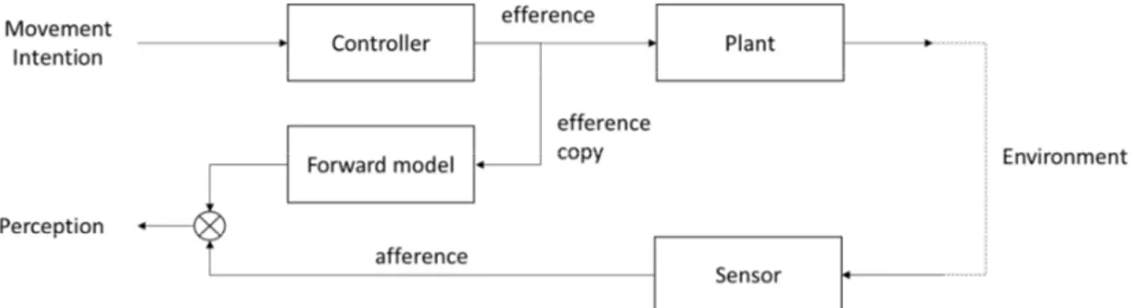
Figure 5. Example of predictive control. The motor system takes an efference copy of the control signals to estimate the state of plant, and use the estimation value as a part of the input in the next-state.
A possible solution to the delay problem in feedback control is to predict the consequence of an action with a forward model (Miall & Wolpert, 1996; Kawato 1999). A forward model simulates the behavior of the body and captures the forward or causal
1.2 Internal models and control schemes 8
relationship between actions and their consequences. In other words, a forward model takes the control signals as input and computes the expected behavior of the plant given these signals. In human motor control, the outflowing and action producing motor
commands generated by the CNS are called an efference. The efference copy is an internal copy of this signal which is used by the forward model to predict the behaviour of the body (Arbib, 2003). The prediction of the forward model xest can be used in a fast
feedback loop to compute the error signal e = xd – xest (see Figure 5). This loop operates
quickly because it does not depend on signals (motor commands and feedback) that must travel to and from the periphery. The efference copy loop can be faster because it operates within the CNS (Desmurget & Grafton, 2000).
Figure 6. Motor learning. In this schema, the motor command u and forward model are used to predict the state of the system xest. This information is combined with the
desired state in a fast feedback loop e = xd – xest. In addition, a feedback signal is compared to the prediction of the forward model in to compute an error signal e' = xest – x that can be used to improve the forward model (dashed line).
This control scheme is an instance of predictive control in the sense that the forward model predicts the behavior of the plant or body. In order to function well, the forward model must be accurate enough so that the prediction provides useful information to control the body behavior in real-time comparing the predicted motor outcomes to actual performance. In predictive control, the feedback can be used to teach the forward model. In this case, the idea is to use feedback to compare the actual behaviour x of the body with the prediction xest of the forward model to inform the CNS how well the
expected action matches its actual external action, e' = xest – x (see Figure 6). Well-established computational learning rules can be used to translate the prediction error e' =
1.2 Internal models and control schemes 9
xest – x into changes in synaptic weights which will improve future predictions (Miall &
Wolpert, 1996).
Figure 7. Coordination of grip force and load force, and a computational model based on internal forward and inverse models (Kawato, 1999).
Studies of the grip force when manipulating an object provide a good example of predictive control. These studies have shown that people are able to adjust the grip force in parallel with the inertial load that results from the movement of the arm without delay. The absence of delay suggests that the motor system is able to predict results of an action (e.g Flanagan and Johansson). To explain these findings, Kawato (1999) suggested the CNS uses a combination of the inverse and forward model. With the use of the efference copy the internal model can predict a future hand trajectory, thus allowing to adjust force to the particular load of the known object (Kawato, 1999). In addition, multiple paired forward inverse models describing how diverse objects and environments can be controlled and learned separately have recently been proposed.
Historically, Francis and Wonham were the first to apply internal model in the context of human motor control (Francis & Wonham, 1976). The concept of internal models is now widely used and supported by numerous behavioral studies (Flash & Hogan, 1985; Wolpert, 1997; Gribble, Ostry, Sanguineti, & Laboissière, 1998; Kawato, 1999).
1.2 Internal models and control schemes 10
Modern control schemes involve both inverse and feedforward models as illustrated in the previous examples. The general characteristics of these models is to mimic the input and output characteristics of body-environment interaction within the CNS.
1.2.4 Forward model in perception
Figure 8. Sensory cancellation. This schema illustrates how the prediction of the forward model might be used to cancel the sensory input. In other contexts, it is thought that the output of the forward model might be combined with the sensory feedback to improve the estimate of the system's state (see text).
Besides of the contribution to motor control, the efference copy and forward model are also thought to play a role in perception (Pickering & Clark, 2014). In particular, the efference copy enables the CNS to compare sensory input (afferences) with predicted consequences of actions in order to distinguish sensory signals that are consequences of an action (reafferences) from sensory signals that are consequences of a change in the
environment (exafferences) (see Figure 8). Since Helmholtz, such a mechanism is thought to play an important role to distinguish situations where the displacement of a target on the retina reflects a movement of the eye or a movement of the target in the space (Helmholtz, 1867). In other words, the sensory prediction might be used to cancel the sensory input when the afferent signal results from an action (von Holst, 1954) . This idea of sensory cancellation has been used to explain, for example, why tactile sensitivity might decrease when one moves (Blakemore, Wolpert, & Frith, 2000; Cullen, 2004). More generally, such a mechanism might play a central role in the perceptual stability of the external world in face of the constant changes of sensory inputs induced by body movements (Gallistel, 2013).
1.3 Haptic perception and the body schema 11
Besides sensory cancellation and perceptual stability, the efference copy might also be simply combined with afferent signals to improve estimate of the current state of the body (Baynes, 2009). For example, it has been proposed that efference copy and forward model play a role in proprioception, that is in the perception of one's own movement (Matthews, 1982). Similarly, the efference copy might give information about the weight of objects that are lifted or about external forces that are resisted (Shergill, 2003).
1.3 Haptic perception and the body schema
The term "haptics", from ancient Greek haptikos ‘able to touch or grasp' refers to perception through touch and manipulation of objects with the upper limb and the hand (El Saddik, Orozco, Eid, & Cha, 2011). It has also been described as “the sensibility of the individual to the world adjacent to his body by the use of his body” (J.J. Gibson, 1966). On the sensory side, it involves tactile perception through the skin and kinesthetic
perception via joints and muscles receptors. Unlike the other four senses (vision, audition, gustation, olfaction), the receptors are not centralized on specific organ but distributed over the entire body. An important characteristics of haptic perception is that it involves movements (exploratory procedures) that are specific to the object material and/or spatial properties of interest (S. J. Lederman & Klatzky, 2009). In other words, haptic perception is an active sense, which has also been called Active Touch (J.J. Gibson, 1966) by opposition with passive touch, where the stimulus is placed on the skin. As such, haptic perception is closely related to the proprioception and kinaesthesia.
1.3 Haptic perception and the body schema 12
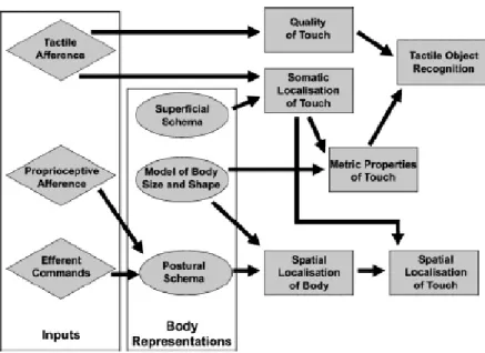
Figure 9. A model of somatoperceptual information processing, highlighting the role of body representations in the construction of somatic percepts. Inputs are depicted as diamond shapes, body representations as ovals, and perceptual processes as rectangles. (Longo et al. 2010 Neuropsychologia)
Haptic perception involves multiple representations of the body and processes. In the somatoperceptual information processing scheme proposed by Longo et al. (see Figure 9), proprioceptive afferents and efferent commands act on the postural scheme, which together with body size information, yield information about the body position (Longo, Azañón, & Haggard, 2010). This information combined with tactile information caused by the contact with an object lead the haptic localization of the object position in space and, possible, the knowledge of its shape via exploratory movements. Tactile afferent might also provide information about the material and superficial properties of the object (softness, texture, temperature, slipperiness, etc.).
The haptic system relies on a complex set of representations and processes, which might also be involved in the body schema. The body schema is a concept in cognitive neuroscience that refers to body representations that are used and involved in action planning and execution (Cardinali, 2011). The term was originally coined by Head & Holmes as “organised models of ourselves” (1912). Another early definition is “A
combined standard against which all subsequent changes of posture are measured, before the changes of posture enter consciousness" (Schilder, 1935). The body schema is a
1.4 Tool use 13
dynamic representation of the body that is play a role in the control and perception of one's own movement and that function is mostly unconsciously. It represents the position and configuration of the body as a volumetric object in space, and is updated with movement (Haggard & Wolpert, 2005).
From a motor control point of view, the body schema containing information about the body size and body masses implements the processes that transform joint angles to spatial position and vice-versa. The body schema might also be involved in the processes to predict the sensory consequences of our action and in predictive control (see above).
1.4 Tool use
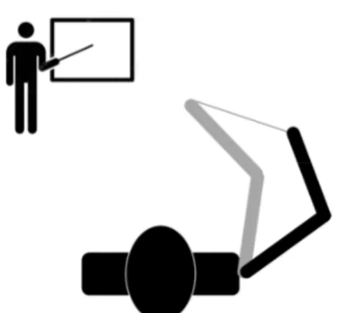
Figure 10. Change of posture required to reach the same position in space with a stick.
Using a tool as important consequences from a control and perceptual point of view because it transforms the relationship between one's action and the environment. For example, reaching a position with the tip of a cane requires a different action than reaching the same position with the hand. Similarly, perceiving the position of the tip of a cane requires taking into action the length of the cane. As shown in Figure 10, using a tool implies the change of the inverse and forward transformations and models involved the planning and execution of movement (e.g. the number of links, the size of the links, etc.). In other words, reaching or pointing with a hand-held tool requires adapting the motor commands to the change of position of the end-effector, which corresponds to the tip of the tool.
1.4 Tool use 14
Remarkably, many studies have shown that our motor system can flexibly adapts to specific tool transformations. For example, Ganesh et al. (2014) looked at the
immediate impact of using a simple tool on pointing accuracy. They observed subjects overshot the target, and suggested that this pattern of error can be seen as a shortened upper limb representation resulting from the tool use. It is somewhat at variance with the plain observation that one is able to switch between using a long stick or using a short pen to point accurately on a board seemingly without any difficulty (Ganesh et al., 2014).
There has been long-term debates on whether precise mental models of the
concrete tool at hand are needed, with information about the tool’s physical properties and mechanics knowledge (precise representation model), or representations for guiding a tool-use action are abstract in the CNS (abstract interval transformation model) (Massen, 2013).
Neuroscientist and neuropsychologists have suggested that tools are incorporated into the body schema, and as a result the representation of the reaching space changes (Berti & Frassinetti, 2000a; Cardinali, 2011; Cardinali et al., 2009; Maravita & Iriki, 2004; Maravita, Spence, Kennett, & Driver, 2002a; Martel, Cardinali, Roy, & Farnè, 2016; Paillard, 1999). For example, it has been suggested that using tools (e.g. mechanical grabber) that physically extends the arm length can modify the somatosensory
representation of body morphology, leading to an elongation of the corresponding part in the body schema with the results of extending the perceived size of the reaching space (Cardinali et al., 2009). Another possibility is that tool representation of the mapping between the hand movements and the end effectors in external environment is at a central level enabling preparation and planning of the movement in advance (Massen, 2013). Tool representation is conceptualized as distinct action schemata that encodes (Massen, 2013). Tool representation is conceptualized as distinct action schemata that encoded the varied mapping between hand and the application of the tool (Norman and Shallice, 1986; Baber 2006). The ability to take into account this sensory motor transformation when planning and executing an action with a tool is crucial for its success.
1.4.1 Neuronal bases of tool use
Functional neuroimaging studies have shown that widespread bilateral parietal, temporal, and frontal regions are involved in tool-related performance (Buxbaum, Shapiro,
1.5 Articulated objects 15
& Coslett, 2014). Geldenberg and Spatt retrieved the functional knowledge from semantic memory, mechanical problem solving and use of everyday tools and objects they found that the functional contribution of parietal lobe is associated with comprehension of functional associations between objects and tools, rather than the selection of grip or appropriate use of the tool (Goldenberg & Spatt, 2009). In contrast, in an fMRI study conducted by van Elk wherein participants had to predict the subsequent use of a
presented tool, results indicated that the left inferior parietal lobe might store hand-posture representations that can be used for planning tool-directed actions as well as for predicting other’s actions (van Elk, 2014).
Some addressed tool-related brain region issues by investigating tool use disorders in left brain-damaged patients. Baumard et al. suggested that the core deficit resulting in left brain-damaged (LBD) patients with apraxia of tool use is the loss of mechanical knowledge (Baumard, Osiurak, Lesourd, & Le Gall, 2014). Lesion analyses for the LBD patients during a hammering action suggested that inferior frontal areas were particularly responsible for impaired performance, whereas right-brain damage (RBD) patients performed normally in most kinematic task aspects (Hermsdörfer, Li, Randerath, Roby-Brami, & Goldenberg, 2013). Buxbaum et al. proposed a componential neuroanatomic model for characterizing the posture and kinematic components for gesture action tasks: for left hemispherical stroke patients, lesioned voxels in the left posterior temporal gyrus were associated with poor performance in posture of tool-related gesture tasks, whereas lesions in left inferior parietal and frontal regions were associated with kinematic
component of gesture tasks in imitation of meaningless movement (Buxbaum et al., 2014).
1.5 Articulated objects
The focus of this thesis is on articulated objects or, more precisely, linkages. By definition, a linkage is an assembly of links and joints in order to provide a desired output motion in response to a specified input motion (Slocum, 2008). A node is an attachment of a joint to a link, and links can have one or more nodes (strictly speaking links must have at least two nodes but we will consider links with one node where the other extremity is held by the user). A joint is a connection between two or more links at their node, which allows motion to occur between the links.
1.5 Articulated objects 16
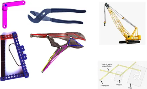
Figure 11. Examples of linkages. Connection between two or more links at their nodes, which allows motion to occur between the links (Slocum, 2008; 2017 CCCME; kisspng.com).
In this thesis, we will consider linkages with revolute and prismatic joints. Both joints allow only a single degree-of-freedom movement. The number of degrees-of-freedom (DOF) of a linkage depends on the number of joints and the structure of the mechanism. For a planar mechanism, the number of degree-of-freedom is given by Gruebler's formula:
F = 3(n-1) - 2 f
where n is the total number of links (including a fixed or single ground link) and f is the total number of joints. The number of degree-of-freedom is equal to the number of input motions needed to define the linkage motion.
Articulated objects have kinematic and dynamic properties that distinguish them from rigid bodies, which raise new issues both on the perception and control sides. Unlike rigid bodies, articulated objects do not have a fixed shape since they are made of parts that can move one relative to another. However, these movements are not completely free because the linkage structure constrains the movement of the links along some directions.
1.6 Thesis outlines 17
In many mechanisms, all links move together in the sense that position of one link determines the position of all other links. In other words, the movement of the whole mechanism might be determined by the movement of one of its part. In fact, mechanisms are often used to transform movements of one kind into movements of another kind. For example, the crank-slider transform a rotational movement in a linear movement (see Figure 11). Another example is the pantograph which transforms the scale of a movement (see Figure 11). When using articulated objects, the user can control the action of the mechanism by moving one of its link. For example, when playing trombone, the user must control the position of the outer tube relative to the inner tube to adjust the tone.
One question of interest is whether people can judge the size of an element (link) of an articulated object from the movements of its parts. In the next chapter, which reports the results of a study on the bimanual perception of object size, we investigated one's ability to perceive haptically (without vision) the length of the links of large pliers by simply moving them. The plier is probably the simplest example of linkage with only two links and one internal degree-of-freedom that allows the two links to rotate around the revolute joint.
Another question of interest is whether the user can predict the movement of one part of the linkage when moving another part of the mechanism. As we have seen in a previous section, predictive control and forward models play a central role in current models of human motor control and haptic perception. One question that we investigated in the third chapter is whether seeing the mechanism can help predict the movement of one part of a linkage when moving another part.
Another difference between rigid bodies and articulated objects is that the dynamic properties of the linkages which changes with the linkage configuration. For example, the inertia tensor of a rigid body is invariant because it does not change shape. In contrast, the spatial distribution of the masses of a linkage and thus its apparent mass will change with its configuration. Another properties of linkage is to transmit forces and this transmission is also affected by the geometry and configuration of the linkage. The last part of this thesis addresses these issues.
1.6 Thesis outlines 18
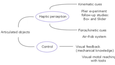
Figure 12. Outline of the thesis
Figure 12 illustrates the work done during thesis, which aimed at understanding better some aspects of the human capacity to perceive haptically the kinematic and
dynamic properties of articulated objects as well as the human capacity to control them. In particular, this thesis includes studies that investigated the role of the two hands in the haptic perception of the size of large pliers, and the utility of seeing the mechanism to control the movement of the end-effector. In addition, we also developed a novel robotic device to perform experiments on the haptic perception of the interaction forces generated by the device.
Besides this introductory chapter, the thesis includes four other Chapters: Chapter 2 investigates factors that influences the perception of the size of large pliers, held with both hands. In particular, it investigates the integration of information from the two hands when judging the size of the pliers and the influence of lifting the object on bimanual integration. This study includes additional experiments with wooden boxes and actuated apparatus with two movable flat surfaces. This study revealed that free manipulation is a factor that promotes bimanual integration by telling the brain that both hands are touching the same object. This Chapter includes a discussion on the place of bimanual integration in current accounts of multisensory integration. A preliminary report was published in World Haptics 2017 international conference, and a full article based on
1.6 Thesis outlines 19
this Chapter has been submitted to Journal of Experimental Psychology: Human Performance and Perception.
Chapter 3 focuses on the influence of visual feedback on the reaching task with tools. It extends previous studies on visuo-motor control tasks with relatively complex tools. The experiments involve six types of 2-degree-of-freedom articulated mechanisms with prismatic and/or revolute joints, and introduce three visual representation conditions, with visual, pre-visual and non-visual feedback. These experiments showed that seeing the mechanism can help to control the movement of the end-effector, which indicate that people must have some internal model of the mechanism(s), which can be used to predict its motion.
Chapter 4 describes the development of AirRob, a novel device that was designed to study the perception of dynamic properties of articulated system. The initial concept was to design a low-friction, planar and modular system with variable link length and masses actuated by motors directly placed at the joints. The second part of the Chapter reports the results of a preliminary experiment that was carried out to understand how people interpret some force fields produced by the device.
2.1 Background 20
Chapter 2
Study one
This study investigate the haptic perception of the size of hand-held pliers, a specific instance of articulated object made of two links attached by a revolute joint. In an initial experiment (Xu & Baud-Bovy, 2017; see Annex A), we measured precision with which people can judge the size of large pliers by simply opening and closing them and the contribution of each hand to this process. We compared performance in unimanual and bimanual conditions, with the pliers that could be fixed (grounded condition) or free to move. The chapter is actually focused a series of follow-up studies on object size perception and bimanual integration with different types of objects, including wooden boxes, an actuated apparatus with two movable flat surfaces and another experiment with large-size pliers, in uni-manual, bimanual grounded and bimanual free conditions. This chapter is the basis of an paper submitted at Journal of Experimental Psychology: Human Performance and Perception (Xu, Risso & Baud-Bovy, submitted). It is followed by a short appendix (Appendix A) that extend some discussions that were not included in the paper.
2.1 Background
Multiple sensory systems provide information about the environment. The brain must continuously process and organize this information, selecting and possibly merging it in a coherent whole. This work focuses on the integration of information coming from two hands holding an object in the absence of vision. While many studies have explored how information from different sensory modalities is combined or merged, fewer studies have investigated how different cues are integrated within the same modality, specifically the haptic modality. The goal of our study was to investigate whether information from the two hands is integrated when subjects estimate the size of an object with both hands. In the following, we start by reviewing previous work on multi-sensory integration in order to introduce the theoretical issues, which are the same whether the information comes from one or more sensory modalities. In particular, understanding how the brain deals with potentially conflictual information and/or when it decides to merge it together are long-standing research questions. We then review the literature on bimanual integration and introduce the objectives of our study.
2.1 Background 21
2.1.1 Early work on multi-modal integration
Early research on multi modal sensory integration focused on situations where there was a conflict between pieces of information provided by different sensory modalities. A classic illustration is "ventriloquism", where the words pronounced by the puppeteer appear to come from the mouth of the puppet in conflict with the audio cues about the sound source (Vroomen, Bertelson, & De Gelder, 2001). Initial findings led to the view that the brain might accommodate such a conflict by simply ignoring one of the two sensory modalities (the stimulus or modality dominance hypothesis). In the case of a conflict between the visual and audio or proprioceptive modality, it was initially suggested that the visual modality dominates (Rock & Victor, 1964), but successive studies revealed a residual influence of the other modalities (Hershberger & Misceo, 1996; McDonnell & Duffett, 1972). This research line revealed that the direction and strength of the inter-sensory bias toward one or the other inter-sensory modality depended on a variety of factors. In a review of this literature, Welch and Warren (1980) discussed evidence that the direction of the intersensory bias might depend on directed attention and/or on the accuracy or appropriateness of each modality. They also propose that the magnitude of the bias depends on the observers' assumption that they are in the presence of a single distal object (the unity assumption) and that the strength of this assumption is also a function of the number of physical properties (e.g., shape, size motion) that are redundantly represented in the stimulus situation (Welch, 1999). When the sensory signals are thought to refer to different objects or events, there would be no sensory conflict and thus no inter-sensory bias.
2.1.2 Optimal (Bayesian) integration
These early observations have since been reinterpreted in light of optimal and Bayesian integration principles, a mathematical framework that allows one to define the best estimate that can be obtained by combining redundant information (Ernst & Banks, 2002). In brief, the optimal integration hypothesis prescribes that the best estimate s12
corresponds to a weighted average between the two sensory cues s1 and s2
= + (1)
where the weights w1 and w2 (w1 + w2 = 1) are proportional to the reliability of the stimulus:
2.1 Background 22
and the reliability Ri = 1/σi
2
is simply the inverse of the noise (variance) of the corresponding cue. Assuming that the information provided by each cue is independent and normally distributed, it can be shown that the optimal (or Maximum Likelihood) estimate s12 that combines the two cues has a variance:
= (3)
which is not only lower than that of the single cues but the lowest possible given the noise associated with each cue. This noise can be determined in behavioural experiments measuring the discrimination thresholds. A consequence of this framework is that, in the presence of a conflict, the bimodal estimate should be biased toward the most reliable sense, and many past observations have been reinterpreted accordingly. In addition, it is also generally held that the two cues are merged together before a decision is made (Ernst & Bülthoff, 2004).
More recently, Bayesian models have been extended to also address the question of when the brain should integrate information. For example, Körding et al. (2007) include the likelihood of two co-occurring signals having a "common cause" in their modelling of causal inference processes. Similarly, Ernst proposed reformulating the problem of integration in terms of a “coupling prior” representing the priori relation between the sensory signals (Ernst, 2007).
2.1.3 The haptic sense and sensory integration within a sensory modality
The haptic sense provides important information to control movement as well as information about our physical environment, especially the objects that we manipulate (Johansson & Flanagan, 2009). By definition, the haptic sense combines proprioceptive inputs coming from muscles, tendons and joints and tactile inputs coming from mechanoreceptors in the skin. The haptic sense can provide information about an object's material properties (softness/roughness, texture, slipperiness, stickiness, etc.), dynamic or kinetic properties (weight, compliance) and geometric or spatial properties (shape, size, position and/or orientation). A general characteristic of the haptic sense is that haptic information is typically acquired sequentially and actively by moving one's hand over an object (James J. Gibson, 1962) and that different movements are used depending on the type of information that needs to be acquired (Susan J Lederman & Klatzky, 1987).
2.1 Background 23
Previous research on the haptic perception of the size or shape of objects has identified various haptic cues that are particularly relevant for our study (Pont, Kappers, & Koenderink, 1997, 1999). First, the size or shape of the object might be derived from the movement of the hand over the object's surface. Second, touch also provides information about the orientation of the object's surface at the contact point (tangent plane). Finally, touch, especially finger pad deformation, might provide information about the local curvature at the contact point. In the literature, position, tangent plane and curvature are known 0th, 1st- and 2nd-order cues (Pont et al., 1997). In addition to these geometric cues, previous research has shown that the tangential component of the interaction force might also influence the perceived shape of the object (Robles-De-La-Torre & Hayward, 2001; Drewing & Ernst, 2006). Finally, the size or shape of hand-held objects can also be inferred from kinetic cues such as their moment of inertia or static torque (Turvey et al. 1998).
As noted above, the principles of multimodal integration apply not only to cues from different sensory modalities but also to different but redundant cues within one sensory modality. For example, there are several studies in the haptic literature suggesting that redundant haptic cues might be weighed according to their reliability. In particular, previous research on curvature perception showed that the weight given to each cue might depend on the size of the object, with 0th-order cues playing a major role for large objects, 1st-order cues playing a major role for medium size objects and 2nd-order cues for small objects (Wijntjes, Sato, & Hayward, 2009). Drewing and Ernst (2006) have also found that geometric and force cues are integrated optimally in a shape discrimination task.
2.1.4 Bimanual integration
In this study, we focus on the haptic perception of the size of an object held with both hands, and whether information from the two hands is integrated optimally. Squeri et al. (2012) investigated whether information from the two hands was integrated optimally in a curvature perception task, where a bilateral robot moved the observer's hand(s) passively along the arc of a circle. They found no significantly different performance in the bimanual conditions with respect to the unimanual conditions. Panday, Tiest and Kappers (2013) asked observers to discriminate the size of large cylinders, with a diameter that varied from 19 to 45 cm (Panday et al., 2013). The cylinders lay on a table and the side(s) was/were explored with one or both hands. Contrary to Squeri et al.’s (2012)
2.1 Background 24
experiment, they found better performance in the bimanual condition. However, in a control condition where the observers had to report the distance between two flat surfaces, they found no difference between the performances in the unimanual and bimanual conditions. To explain these results, Panday et al. (2013) proposed that 2nd-order cues related to the deformation of the hand on the cylinder might be integrated but not 0th-order cues related to the position of the hand in space. They hypothesized that 2nd-order cues consistent with cylindrical shape would suggest to the observer that the hands were touching the same object while 0th-order cues only would not be able to elicit this impression. They also attributed the absence of integration in Squeri et al. (2012) to the fact that participants experienced only 0th-order position cues while the robot moved one or both of their hands along the curved trajectory. This conclusion is also in line with the results of Wong, Wilson, Kistemaker and Gribble's (2014) more recent study in which bimanual proprioceptive acuity was not found to be significantly better than the best unimanual performance.
2.1.5 Object Grounding and the Unity Assumption
The main objective of this study is to investigate factors that might contribute to bimanual integration. As reviewed above, previous studies on haptic bimanual perception tasks have given contrasting results and surprisingly weak evidence of bimanual integration despite the fact that many motor tasks involve both hands. The absence of integration also stands in contrast with the tight integration in the control of the two hands as demonstrated by the difficulty in accomplishing truly independent movements with only one hand (reviews in Ivry, Diedrichsen, Spencer, Hazeltine, & Semjen, 2004; Swinnen & Wenderoth, 2004). A critical feature of previous studies on bimanual integration that might be relevant in this context is that they all involved grounded objects. In other words, the objects could not be moved and no force was transmitted between hands. In contrast, the position of the hand-held objects involved in bimanual tasks is typically not constrained. This is the case when holding a tray or driving for example. In this type of bimanual action, the movement of the hand-held object and the hand are usually coupled and the force applied by one hand to the object is transmitted to the other hand and vice-versa (internal force). The main objective of this study is to test whether bimanual integration is influenced by grounding. Specifically, we hypothesize that bimanual integration might be enhanced when the object is not grounded and thus free to
2.2 Experiment 1: box size discrimination 25
move. The hypothesis is that the motion coupling and force transmitted between the two hands might be used by the brain as a sign that two hands are holding the same object (unity assumption), thus triggering or enhancing bimanual integration (Welch & Warren, 1980).
In the following, we report the results of three experiments that investigated whether information from the two hands is integrated when estimating the size of an object bimanually, and whether grounding an object had influence on bimanual integration. In the first experiment, the task was to judge the size of wooden boxes. A box could lie on the table (grounded condition) or be lifted with both hands (free condition). In the unimanual conditions, the box was centered on the body mid-line so that it was possible to determine its size by touching one side with one hand. In the second experiment, we used an actuated apparatus with two movable flat surfaces, which resembled the grounded setup used by Panday et al. (2013). Finally, in the third experiment, we used large-size pliers and asked the participant to judge their size by opening and closing them. In the bimanual conditions, the fulcrum of the pliers could be fixed (grounded condition) or free to move. Our results show that grounding the manipulated object has an effect on bimanual integration, but it is not a necessary condition. With familiar objects such as wooden boxes, bimanual integration might also occur in the grounded condition. This is not the case, however, for less familiar objects such as the actuated apparatus used in the second experiment or the relatively complex tools used in the third experiment.
2.2 Experiment 1: box size discrimination
2.2.1 MethodsParticipants. Nineteen participants, nine women and ten men (mean age 26.47 ± 3.89 years), participated in the experiment. All participants were right-handed except for one. None of the participants reported any known hand or neuromuscular disorder. All participants were naïve as to the goal of the experiment and had no previous experience with the task. One participant was excluded from the data analysis because he did not perform the task well enough to estimate the sensory threshold. The experiment was approved by the Ethics Committee of the Region of Liguria, and conducted according to the ethical principles defined by the Helsinki Declaration. All participants gave their informed consent before the experiment.
2.2 Experiment 1: box size discrimination 26
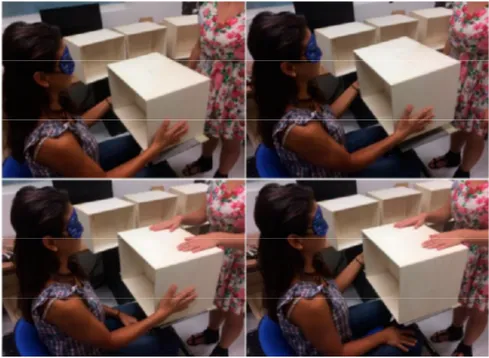
Apparatus and stimuli. Stimuli consisted in nine equally weighted wooden boxes sized 30 cm x 30 cm x (Variable Length) ranging from 32 to 48 cm by 2-cm steps. The 40 cm length box was used as the standard stimulus, while other boxes were used as comparison stimuli. All boxes were built to have the same weight (1413 ± 30 gr) and centre of mass (Figure 13).
Figure 13. The figure represents a blindfolded participant haptically interacting with a wooden box in the four experimental conditions. The top panels show the bimanual grounded (left) and free (right) conditions. In the bimanual free condition, the participant lifted the box a few centimeters above the table. The bottom panels represent the unimanual condition.
Experimental procedure and task. Participants were blindfolded before entering the experimental room so that they would not see the stimuli at any time. In the experimental room, the participants sat on a fixed chair with their bodies at 20 cm from the edge of a table. Before each experimental session participants were asked to point exactly in front of their body mid-line at least three times with arms extended and hands joined. The average position was marked on the table and used to centre the boxes during their presentation.
The task was a size-discrimination two-alternative-forced-choice task. During each trial, participants felt the size of two boxes in succession and at the end of the trial reported verbally which one was the largest.
2.2 Experiment 1: box size discrimination 27
The experiments included four conditions. In the unimanual conditions, each participant had to touch the side surface of the box with the left or right hand. In these conditions, he/she was asked to focus on the distance between the touched side of the box and the body mid-line. In the bimanual grounded condition, the experimenter maintained the box throughout the presentation to avoid movement while the participant touched the two lateral surfaces of the boxes with both hands for up to 5 seconds. In the bimanual free condition, the participant lifted the box a few centimetres, then put it back to its initial position. In both bimanual conditions, participants were asked to focus on the size of the box. Before the beginning of the experiment, the participants practiced the task in each condition until they felt comfortable.
Each trial included the presentation of the standard stimulus (40 cm) and one of the eight comparison stimuli. The order of presentation of the comparison and standard stimuli was randomized. Each comparison stimulus was presented seven times in each condition (method of the constant stimuli (Fechner, 1860), yielding a total of 224 trials. The experiment included seven blocks of 32 trials, which were subdivided into four sub-blocks of eight trials. Each sub-block corresponded to a condition and included all comparison stimuli in a random order. The order of presentation of the different conditions inside each block was randomized as well. The total duration of the experiment was 90-120 minutes per participant, divided into two sessions.
2.2.2 Data Analysis
For each participant and condition, a cumulative normal probability distribution was fitted to the responses using maximum likelihood estimation to obtain a psychometric function representing the probability of judging the comparison stimulus as larger than the standard stimulus. For each psychometric curve, we computed the point of equality (PSE), i.e. the box size perceived as larger than the standard distance in 50% of the trials, and the discrimination threshold (or discrimination limen, DL), which corresponded to the difference between the PSE and the box size perceived to be larger than the standard in 75% of the trials.
To statistically test an effect of the exploration condition, we performed a non-parametric Friedman test for repeated measures on the discrimination thresholds and PSE of unimanual and bimanual conditions. Whenever an effect was found, we tested the
2.2 Experiment 1: box size discrimination 28
difference between conditions with two-tailed paired Wilcoxon signed-rank tests. To test whether integration took place, we computed the bimanual threshold predicted by optimal integration principles (Maximum Likelihood Estimation) for each participant. We tested whether the observed bimanual discrimination thresholds were smaller than or equal to the predicted MLE thresholds with one-tailed paired Wilcoxon signed-rank tests. Finally, we also examined if individual bimanual thresholds corresponded to the predicted MLE thresholds. In particular, we used Pearson-product-moment correlation to test the relationship between the observed values and the MLE predictions. For all tests, the level of statistical significance was set at 5% (Error Type I α = 0.05).
2.2.3 Results
Figure 14. Results of the box size discrimination experiment. The top left panel represents the mean PSE (on the y-axis) for each condition (x-axis): Right (R), left (L), bimanual grounded (BG), and bimanual free (BF) condition. Vertical bars represent the standard error. The dotted line represents the standard box size (40 cm). The top right panel represents the mean discrimination thresholds (on the y-axis) for the four conditions (x-axis); the dotted line represents the predicted MLE threshold. The bottom panels show correlations between the individual discrimination thresholds predicted by MLE and those observed in the bimanual grounded condition (bottom left panel) or bimanual free condition (bottom right panel).
Figure 14. shows the mean haptic PSE (top left panel) and thresholds (top right panel) of the participants for the four experimental conditions. The differences between
39.0 39.5 40.0 40.5 41.0 R L BG BF P S E ( c m ) Condition 0.0 0.5 1.0 1.5 2.0 2.5 3.0 R L BG BF D L ( c m ) Condition 0 1 2 3 4 1 2 3 4 5 D L ( G ro u n d e d ) DL (Predicted) 1 .0 1.5 2.0 2.5 3.0 3.5 1.0 1.5 2.0 2.5 3.0 D L ( F re e ) DL (Predicted)