Sigla di identificazione Distrib. Pago
~ Ricerca Sistema Elettric.o NNFISS - LP2 -055 L 1
Titolo
Preliminar
y v
a
lidation of the coupling between a pr
imary
system and a containment co
de
Ente emittente CIRTEN
PAG
I
NA DI GU
A
R
DIA
Descrittori
Tipologia del documento:
Collocazione contrattuale:
Rapporto Tecnico
Accordo di programma ENEA-MSE: tema di ricerca "Nuovo
nucleare da fissione"
Reattori nucleari ad acqua, Reattori nucleari evolutivi,
Analisi disicurezza
Argomenti trattati:
Sommario
The present report describes the preliminary assessment of the coupling methodology adopted to link a nuclear reactor thermal-hydraulic primary system code to a containment system code, set up in the frame oftask LP2-E.1 ofthe AdP PAR2008-09 assigned to CIRTEN.
The coupled codes are the RELAP5 Mod3.3 patch 3 and the Gothic version 7.2b(QA). The RELAP5 code was provided to the University of Pisa by ISPRA together with the FORTRAN source prograrn, while the executable version of the Gothic code and limited rights to use it for the purposes of the present work were acquired from Numerical Applications, Inc. (NAI). A
companion report describes the choices made inthe coupling of the two codes.
Different test cases were defined and run in order to check the capabilities of the coupled codes.
The considered cases are simple enough to grant the possibility to clearly ascertain if the flow of
information between the two codes is correct enough, in the limits of the scope of the present
work. The simplest cases involve the injection or extraction ofwater and/or noncondensable gases into or from Gothic volumes by two different junctions; a sample pressurised water blowdown case from a ves sel is also considered, with and without gravity driven injection of water to the vessel. The analysed calculation cases provide adequate confidence inthe adequacy of the
performed coupling work, though future improvement of the coupling strategies can be envisaged on the basis of what already discussed in the companion report.
Note Copia n. In carico a: 2 NOME FIRMA 1 NOME FIRMA
O EMISSIONE
j?/
o
1fot{
NOME P. Meloni P. Melonidi 51
CIRTEN
Consorzio Interuniversitario per la Ricerca TEcnologica Nucleare
UNIVERSITA’ DI PISA
Dipartimento di Ingegneria Meccanica, Nucleare e della Produzione
Preliminary validation of the coupling
between a primary system and a containment code
Autori
W. Ambrosini A. Manfredini
CERSEUNIPI RL 1083/2011
ABSTRACT
The present report describes the preliminary assessment of the coupling methodology adopted to link a nuclear reactor thermal-hydraulic primary system code to a containment system code, set up in the frame of task LP2-E.1b of the AdP assigned to CIRTEN.
The coupled codes are the RELAP5 Mod3.3 patch 3 and the Gothic version 7.2b(QA). The RELAP5 code was provided to the University of Pisa by ISPRA together with the FORTRAN source program, while the executable version of the Gothic code and limited rights to use it for the purposes of the present work were acquired from Numerical Applications, Inc. (NAI). A companion report describes the choices made in the coupling of the two codes.
Different test cases were defined and run in order to check the capabilities of the coupled codes. The considered cases are simple enough to grant the possibility to clearly ascertain if the flow of information between the two codes is correct enough, in the limits of the scope of the present work. The simplest cases involve the injection or extraction of water and/or noncondensable gases into or from Gothic volumes by two different junctions; a sample pressurised water blowdown case from a vessel is also considered, with and without gravity driven injection of water to the vessel.
The analysed calculation cases provide adequate confidence in the adequacy of the performed coupling work, though future improvement of the coupling strategies can be envisaged on the basis of what already discussed in the companion report.
INDEX
ABSTRACT ... II INDEX ...IV
1. INTRODUCTION... 1
2. SUMMARY OF THE COUPLING STRATEGY ... 5
3. ADDRESSED SAMPLE CASES AND OBTAINED RESULTS ... 13
3.1CONTAINMENT VOLUME DEPRESSURIZATION WITH AIR ONLY... 13
3.1.1 Calculation case description... 13
3.1.2 Obtained results... 14
3.2CONTAINMENT VOLUME DEPRESSURIZATION WITH AIR AND STEAM... 17
3.2.1 Calculation case description... 17
3.2.2 Obtained results... 17
3.3EXTRACTING LIQUID FROM A SUMP... 19
3.3.1 Calculation case description... 19
3.3.2 Obtained results... 20
3.4PRESSURISING A CONTAINMENT VOLUME WITH AIR... 23
3.4.1 Calculation case description... 23
3.4.2 Obtained results... 24
3.5PRESSURISING A CONTAINMENT VOLUME WITH AIR AND STEAM... 26
3.5.1 Calculation case description... 26
3.5.2 Obtained results... 27
3.6FILLING A CONTAINMENT VOLUME WITH WATER... 29
3.6.1 Calculation case description... 29
3.6.2 Obtained results... 30
3.7WASHING A CONTAINMENT VOLUME WITH AN AIR FLOW... 32
3.7.1 Calculation case description... 32
3.7.2 Obtained results... 32
3.8WASHING A CONTAINMENT VOLUME WITH AIR AND STEAM... 34
3.8.1 Calculation case description... 34
3.8.2 Obtained results... 34
3.9VESSEL BLOWDOWN IN A DRY CONTAINMENT... 36
3.9.1 Calculation case description... 36
3.9.2 Obtained results... 37
3.10VESSEL BLOWDOWN IN A CONTAINMENT WITH GRAVITY DRIVEN INJECTION... 40
3.10.1 Calculation case description... 40
3.10.2 Obtained results ... 41
4. CONCLUSIONS ... 43
1. INTRODUCTION
A companion report [1] describes the motivations for coupling primary system and containment codes, in view of the strong links existing between the reactor system and the containment compartments in innovative and small and medium sized reactor concepts.
In summary, in these reactors flows of water, steam and noncondensable gases from and to reactor compartments should be carefully simulated in order to predict the postulated accident scenarios taking into account the time evolution of each environment. Passive systems, whose use is made in many proposed reactor concepts, involve in fact driving forces that trigger important safety functions, whose effectiveness depends on the instantaneous status of both primary system and containment. A classical example of such functions is gravity driven injection of emergency coolant, that can be obtained only when pressures in the reactor and in the containment atmospheres are close enough to enable an hydrostatic head to be effective in delivering flow to the reactor vessel.
The already mentioned companion report [1] also describes the choices adopted in coupling two well-known primary system and containment codes, being the RELAP5 Mod3.3 patch 3 [2-3] and the Gothic version 7.2b(QA) [4] codes, that are widely used for primary system and containment safety analyses. The work allowed to obtain capabilities of simulating flows of water, steam and a noncondensable gas (only air for the time being) between Gothic and RELAP5 volumes, exchanging the needed information at boundary conditions and assigning to RELAP5 the task to evaluate flow rates. The coupling work required to perform changes in two RELAP5 routines and to recompile the whole source program, linking it to an interfacing routine in C language that manages the functions of synchronisation of the two codes and of exchanging the needed information between them.
In summary, the achieved coupling capabilities allow to perform the following modelling choices:
• link multiple junctions of RELAP5 (up to 100) with corresponding flow paths and boundary conditions in Gothic;
• exchange both liquid water and steam and air in both directions.
Needless to say, it is important that the flows of mass and energy are interpreted coherently by the two codes and the preliminary validation work described in this report is aimed at showing capabilities and critical aspects in this regard.
Among the challenging aspects that were overcome in the coupling work in relation to information exchange, the following can be mentioned:
• differences in the properties of fluids evaluated by the two codes:
this aspect represents an unavoidable difficulty, that was partly mitigated in the case of the exchanges of air; in fact, the zero levels of internal energy for noncondensable gases are different in the two codes and, just for air, the problem was partly solved at the level of information exchange, by adding an appropriate constant to the air internal energy during data transfer;
• codes synchronisation and transfer of flows:
at the present stage, it was considered risky and premature to change the philosophy embedded in the C information exchange routine set up by Numerical Applications, Inc. (NAI), leaving the exchange of flows to occur at the synchronisation times identified on the basis of the respective time advancement steps; it is anyway clear that an accurate conservation of mass and energy in the coupling can be obtained only by time integration of the mass and enthalpy flows over the synchronisation time intervals, rather than by the mere exchange of the instantaneous information at prescribed times; • differences in the flow models adopted by the two codes:
the different number and type of field equations in the two codes make at the moment difficult to deal with particular conditions as, for instance, countercurrent flows at junctions that, though calculated by RELAP5, can be transferred to Gothic only in terms of an overall mixture flow rate and of the related specific enthalpy, i.e., a not completely satisfactory model to represent the real situation.
Having in mind the above challenges, the work performed in this preliminary validation attempt was mainly devoted to check that the exchange of flows in either direction is correct enough and leads to reasonable results. In this purpose, several calculation cases were run involving one or two RELAP5 junctions simultaneously linked with corresponding Gothic flow paths and boundary conditions. The obtained flows are compared on either side, in order to show agreement, and the effects of the flows in terms of mass and energy balances in the two codes are evaluated. In particular, Gothic volume sweeping by noncondensable gas and steam provided by RELAP5 and filling and emptying of Gothic volumes by water flows are considered to demonstrate the effectiveness of the adopted coupling strategy. In addition, a simple vessel blowdown case is run, with and without gravity driven fluid injection to the primary system, in order to present a further realistic application of the coupled codes, giving the flavour of the potential achieved by the coupling work for the intended purpose of analysing thermal-hydraulic transients in nuclear reactor primary systems and containments. In the case of
several node stacks was utilised, pointing out how the relevant features of the Gothic code may be adopted to achieve an intended effect in coupling.
2. SUMMARY OF THE COUPLING STRATEGY
As mentioned in the report on coupling methodology [1], limitations in the capabilities to simulate simultaneous flows of water and noncondensable gases at Gothic boundary conditions suggested that any given RELAP5 junction must be coupled with two boundary conditions and flow paths of Gothic. This is to allow for accomplishing the following functions:
• first boundary condition and flow path: injection of water/steam mixtures from RELAP5 to Gothic in the case of forward flow and extraction of steam/water plus noncondensable gas mixtures from Gothic to RELAP5 in the case of backward flow; • second boundary condition and flow path: injection of noncondensable gas from
RELAP5 to Gothic in the case of forward flow only.
Figure 1 describes the situation according to the above description.
Figure 1. Arrangement of RELAP5 and Gothic elements and flow of information between the codes at each RELAP5 junction connected to Gothic in the presently adopted
methodology
The variables transferred by the information flows pointed out in the above figure at each RELAP5 junction connected to Gothic are the following:
• From RELAP5 to Gothic
1. the water/steam mass flow rate: this value must be assigned to the first of the two junctions injecting mass into Gothic;
RELAP5 Junction
RELAP5
Time Dependent Volume 1st Gothic BC
2nd Gothic Flow Path
Gothic Volume
Mass Flow Rate and Enthalpy of Water/Steam
Mass Flow Rate Pressure and Temperature of
the Noncondensable Gas
1st Gothic Flow Path 2nd Gothic
BC Information necessary to assign
2. the flow averaged enthalpy of the water/steam mixture: this is the specific enthalpy to be assigned to the above flow;
3. the noncondensable gas mass flow rate: this flow rate must be assigned to the second junction, injecting only gas;
4. pressure in the RELAP5 volume upstream the junction: this is necessary to define the thermodynamic properties of both the water/steam and of the noncondensable gas to be injected into the Gothic volume;
5. temperature in the RELAP5 volume upstream the junction: also this variable is necessary to define the thermodynamic properties of the noncondensable gas to be injected into the Gothic volume.
• From Gothic to RELAP5
1. pressure in the containment volume;
2. specific enthalpy of liquid in the containment volume; 3. specific enthalpy of steam in the containment volume;
4. specific enthalpy of the noncondensable gas in the containment volume; 5. liquid level in the containment volume;
6. elevation of the junction from the bottom of the containment volume; 7. height span of the junction in the containment volume;
8. density of the liquid phase in the containment volume;
9. density of the vapour (gas plus steam) phase in the containment volume; 10. mass fraction of steam in the containment volume.
The exchange of information from RELAP5 to Gothic occurs automatically once the proper identification of linked junctions is made in both the RELAP5 input deck and in the “relaptogothic.dat” file (see [1] for details). However, on the Gothic side, both the five variables passed by RELAP5 and the ten variables to be assigned from Gothic to RELAP must be directly managed in the input deck of the containment code, requiring the identification of the exact variables to be transferred and their assignment as inter-process exchange variables in the appropriate code menus (see [1] for details).
Figure 2. Arrangement of Gothic volumes, flow paths and boundary conditions corresponding to two RELAP5 junctions connected to Gothic
As an example, the general topology shown in Figure 2 is suggested for the case of two
RELAP5 junctions linked to a same Gothic volume at two different heights injecting (or extracting) fluid into (from) a Gothic volume. It must be clarified that the left time dependent volume in each piping branch is introduced here only as an example and that in a real case it may be replaced by arbitrary sets of RELAP5 hydrodynamic and heat structure components of any complexity.
In the sketch it is implied that:
• each RELAP5 linked junction and its upstream volume (to be clearly identified in the “relaptogothic.dat” file) supply information to the two corresponding flow paths in Gothic for the assignment of flow rate, enthalpy and composition in case of forward flow;
• in turn, each involved RELAP5 time dependent volume receives from Gothic the boundary conditions to be assigned downstream the junction, for use in both forward and backward flow; actually, in the case of forward flow, only the junction back pressure represents an interesting boundary condition, while all the other boundary conditions play a role only in the case of backward flow.
As it is clearly understandable, it is quite important that the linked junctions and the upstream and downstream volumes are unambiguously identified and that the positive flow in the RELAP5 junction is defined for flow going from the junction to the time dependent volume, i.e., from RELAP5 components to Gothic components.
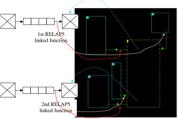
In most of the following examples, a variant of the above sketch will be adopted, as shown in Figure 3.
1st RELAP5 linked Junction
2nd RELAP5 linked Junction
Figure 3. Arrangement of Gothic volumes, flow paths and boundary conditions corresponding to two RELAP5 junctions connected to Gothic
as used in most of the addressed calculation cases
In this variant, to be considered as a non standard use of the coupling capabilities, the first RELAP5 junction linked to Gothic (being a time dependent junction) is upstream a pipe, while the time dependent volume receiving the boundary conditions from Gothic is downstream it. This produces an unconventional situation in which the flow rate is calculated considering the hydraulic impedance of the pipe (except for the use of a time dependent junction that forces it), as the back pressure is not assigned in the volume immediately downstream the junction. This artifice was used in order to inject directly into the containment a prescribed flow with well defined thermodynamic properties, avoiding the influence of the pipe on the injected flow (e.g., expansion effects due to pressure decrease).
In this arrangement, therefore, the two RELAP5 piping branches, used respectively for injection (the upper one) and extraction of mass (the lower one) are composed as follows:
• injection piping branch: from left to right in the figure, a time dependent volume, a time dependent junction, a pipe, a trip valve and a time dependent volume;
• extraction piping branch: from left to right in the figure, a time dependent volume, a single junction, a pipe, a trip valve and a time dependent volume.
1st RELAP5 linked Junction (time dependent junction) 2nd RELAP5 linked Junction
Acting on the trip logics and/or on the forward and backward pressure loss coefficients at the junctions, it is possible to obtain different configurations:
• a single piping branch injecting flow (the upper one): this is obtained by making false the opening trip of the trip valve in the lower piping branch (Figure 4a);
• a single piping branch extracting flow (the lower one): this is obtained by making false the opening trip of the trip valve in the upper piping branch and assigning at zero the flow injected by the time dependent junction in the upper piping branch (Figure 4b); • two piping branches simultaneously injecting and extracting flow: this is obviously
obtained by making true the opening trip of both trip valves and enabling injection in the upper piping branch (Figure 4c).
a) injection only b) extraction only
c) simultaneous injection and extraction
Figure 4. Different flow combinations as used in the sample test cases
From the above description, it can be understood that the use of any kind of RELAP5 junctions (single, time dependent, valve, etc.) makes little difference in the coupling, giving a considerable degree of freedom in choosing the vector nodes (“junctions”, in RELAP5 jargon) to be linked to Gothic. On the other hand, though it is not mandatory that the volume downstream a RELAP5 linked junction is a time dependent volume (see the above unconventional use of components), nevertheless boundary conditions in terms of pressure, specific internal energy of the liquid and the gas phases, void fractions and noncondensable quality can be assigned only to time dependent volumes.
As a further example of use of different coupling topologies in the present sample applications, the case of a vessel blowdown, schematically reported in Figure 5, can be considered.
Figure 5. Arrangement of Gothic volumes, flow paths and boundary conditions for the case of the vessel blowdown
In this case, a vertical pipe component including 20 volumes and simulating the vessel is connected at different heights to the two horizontal piping branches, thus replacing the two left time dependent volumes used in the previous arrangements. The upper piping branch simulates the break and contains (from left to right) a single junction, a pipe, a trip valve (the one linked to Gothic) and a time dependent volume; the lower piping branch simulates a gravity driven injection line, taking water from the containment sump, and contains (from left to right) a single junction, a pipe, a trip valve and a time dependent volume.
For the trip valve in the upper piping branch, the flag for calculating critical flow was activated, in order to simulate the addressed vessel blowdown scenario, while the trip valve in the lower piping branch was assigned a very large forward pressure drop coefficient (order of 10100), in order to automatically behave like a check valve.
If only the upper trip valve is activated, the gravity driven injection is excluded and the effect of the blowdown can be studied without the action of passive systems. This allows to compare the obtained results with analytical estimates for containment pressure
1st RELAP5 linked Junction
2nd RELAP5 linked Junction
water from the containment sump (assumed full of water in similarity with an IRWST) will occur, roughly as soon as the pressure in the vessel will become lower than the one in the containment plus the hydrostatic head of the water level in the sump.
The two situations are depicted in Figure 6. It is remarked that in this case the more conventional arrangement of RELAP5 junctions and time dependent volumes linked to the containment is adopted, as it is advisable for any realistic simulation.
a) blowdown only b) blowdown with gravity driven injection
Figure 6. Arrangement of Gothic volumes, flow paths and boundary conditions for the calculation of the vessel blowdown in the two considered cases
The following chapter describes the results of the considered sample calculations based on the above described topological choices.
3. ADDRESSED SAMPLE CASES AND OBTAINED RESULTS
3.1 Containment volume depressurization with air only
3.1.1 Calculation case description
In the first sample calculation, the fast depressurization of a large colume filled with pure air is simulated. The compartment has a free volume of 1000 m3 and the initial pressure and temperature of the air are 200000. Pa and 355.5 K, respectively. No steam is initially present inside the containment (RH = 0%). The containment is simulated using a lumped Gothic control volume linked to two RELAP5 piping branches (Figure 7). The opening trip of the valve in the upper piping branch is forced to be false, while the flow injected by the time dependent junction in the upper piping branch is assigned to zero, as shown in the
Figure 4-b.
Figure 7. RELAP5/Gothic model for the sample calculation n.1
As in all the other sample calculations, no heat structure is simulated for the containment and the rapid depressurization of the can be assimilated to an adiabatic expansion of the gas. This allows to compare the obtained results with analytical estimates for the final values of the tank pressure and temperature. The trip valve allowing the depressurization
of the tank is opened after 10 s since the beginning of the test, while the coupling between the two codes is activated 5 s before the valve opening.
3.1.2 Obtained results
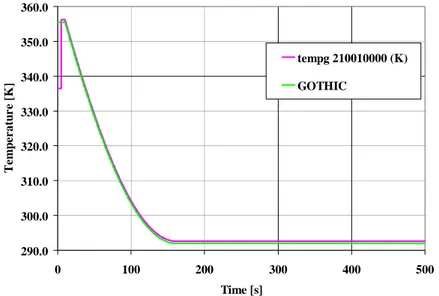
Figure 8 reports the pressure values calculated in the volume by the Gothic code and the value transferred to RELAP5 in one of the two time-dependent volumes of the two piping branches, the upper one in the particular case of the figure. As it can be noted, the two pressure are the same, testifying for the correctness of the transferred information and during the containment volume depressurization they reach the common level of 105 Pa imposed in the time dependent volume 190, as expected. Similarly, the values of the noncondensable gas temperature calculated by Gothic and transferred to RELAP5 (Figure 9) are very close, though not exactly equal; the little discrepancy, in the order of 0.6 °C is due to the different thermodynamic properties evaluated by the two codes, even after equalisation of the internal energies at 0 °C.
9.00E+04 1.10E+05 1.30E+05 1.50E+05 1.70E+05 1.90E+05 2.10E+05 0 50 100 150 200 250 300 350 400 Time [s] Pres su re [ P a ] p 110010000 (Pa) GOTHIC
290.0 300.0 310.0 320.0 330.0 340.0 350.0 360.0 0 100 200 300 400 500 Time [s] T e m p e r a tu re [ K ] tempg 210010000 (K) GOTHIC
Figure 9. Sample case n. 1 – Atmosphere temperature
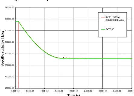
An effect of the explicit coupling between the two codes can be observed comparing the trends of flow rate calculated by RELAP5 and plotted on the basis of the values available in the two codes, that can be seen to be the same as expected in Figure 10; this effect is represented by the oscillations observed in flow rate after pressure equalization between the containment volume and the lower RELAP5 piping branch, a clear effect of the delays in transferring information from one step to another. Figure 11 shows the substantial equality of fluid specific enthalpy calculated by the two codes after the start of information exchange at 5 s. Figure 12 is also introduced to show an interesting feature triggered by the mentioned oscillations; as it can be noted, the flow of noncondensable gas is subdivided in forward and backward directions among the two different flow paths serving for the purpose, in agreement with the adopted coupling strategy.
-12.00 -10.00 -8.00 -6.00 -4.00 -2.00 0.00 2.00 0 50 100 150 200 250 300 350 400 Time [s] M a ss F low R a te [k g/ s] mflowj air 205000000 (kg/s) GOTHIC
Figure 10. Sample case n. 1 – Air mass flowrate
400000.00 420000.00 440000.00 460000.00 480000.00 500000.00 520000.00 540000.00
0.00E+00 5.00E+01 1.00E+02 1.50E+02 2.00E+02 2.50E+02 3.00E+02 3.50E+02 4.00E+02
Time (s) S p ec if ic en th a lp y [ J /k g ] flenth / mflowj 205000000 (J/kg) GOTHIC
Figure 11. Sample case n. 1 – Air specific enthalpy
3.2 Containment volume depressurization with air and steam
3.2.1 Calculation case description
This sample calculation is very similar to the previous one, except for the initial content of steam in the atmosphere of the tank (RH = 100%). The tank is still simulated using a lumped Gothic control volume linked to two RELAP5 piping branches (Figure 7). The opening trip of the valve in the upper piping branch is forced to be false, while the flow injected by the time dependent junction in the upper piping branch is assigned to zero, as shown in the Figure 4-b.
No heat structure is simulated in the tank, as in the previous case, but the rapid depressurization of the air/steam mixture inside the tank causes a partial condensation “in bulk” of the steam with a formation of a pool at the bottom of the tank. The aim of this test was to verify the correct transfer of a steam/air mixture from a containment volume (simulated with the Gothic code) to the primary side (simulated with the RELAP5 code). The trip valve allowing the depressurization of the tank is opened after 10 s since the beginning of the test, while the coupling between the two codes is activated 5 s before the valve opening.
3.2.2 Obtained results
Figure 13, Figure 14 and Figure 15 present similar information as for the previous case and similar comments apply. On the other hand, in Figure 16 it is interesting to note the close agreement of the liquid temperature calculated for the pool in Gothic and the one for the liquid phase in RELAP5, a sign that water properties are similar in the two codes.
9.00E+04 1.10E+05 1.30E+05 1.50E+05 1.70E+05 1.90E+05 2.10E+05 0 50 100 150 200 250 300 350 400 Time [s] Pres su re [ P a ] p 110010000 (Pa) GOTHIC
335.0 340.0 345.0 350.0 355.0 360.0 0 100 200 300 400 500 Time [s] T e m p e r a tu re [ K ] tempg 210010000 (K) GOTHIC
Figure 14. Sample case n. 2 – Atmosphere temperature
-12.00 -10.00 -8.00 -6.00 -4.00 -2.00 0.00 2.00 0 100 200 300 400 500 Time [s] S tea m /a ir m a ss f lo w ra te (k g /s) mflowj tot 205000000 (kg/s) GOTHIC
Figure 15. Sample case n. 2 – Steam/air mass flowrate
335.0 340.0 345.0 350.0 355.0 360.0 0 100 200 300 400 500 Time [s] T e m p e r a tu re [ K ] tempf 210010000 (K) GOTHIC
Figure 16. Sample case n. 2 – Liquid temperature
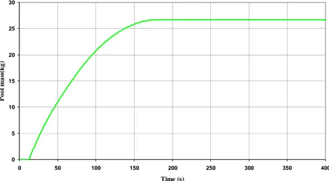
Two effects of bulk condensation occurring because of atmosphere cooling are shown in Figure 17 and Figure 18, being the increase of pool mass and of the
depressurization of the Gothic volume causes a decrease of both the total pressure and the partial pressures of the two components of the initially saturated atmosphere. As it can be noted, after reaching the lowest pressure these processes are stopped.
0 5 10 15 20 25 30 0 50 100 150 200 250 300 350 400 Time (s) P o o l m a ss( k g )
Figure 17. Sample case n. 2 – Pool mass
0.80 0.85 0.90 0.95 1.00 1.05 0 100 200 300 400 500 Time [s] N o nc onde ns abl e m a ss f rac ti on [ -] quala 210010000 GOTHIC
Figure 18. Sample case n. 2 – Noncondensable mass fraction
3.3 Extracting liquid from a sump
3.3.1 Calculation case description
In this sample calculation the emptying of a large tank filled with a mixture of air and steam and with a 0.3 initial liquid volume fraction is simulated. The aim of the test was to verify the correct transfer of water from a containment volume to the primary side, while a simultaneous air mass flowrate from the primary system to the containment assures the
pressure balance between the two systems. The tank has a free volume of 1000 m3 and the pressure and temperature of the atmosphere are 100000. Pa and 313.15 K, respectively. The initial relative humidity of the atmosphere is 100%. The pool (300 m3) inside the tank is initially in thermal equilibrium with the atmosphere. The tank is simulated using a Gothic control volume subdivided into 10 subvolumes in order to properly take into account the hydraulic head of the pool at the linked junction. The control volume is linked to the two usual RELAP5 piping branches (Figure 19). The opening trips of the valves in the upper and lower piping branches are forced to be true after 10 s since the beginning of the test, so that a simultaneous injection of air and extraction of water is obtained, as shown in the Figure 4-c. The lower piping branch is connected to the containment volume at a height of 0.5 m from the floor. The coupling between the two codes is activated 5 s before the valve opening.
Figure 19. RELAP5/Gothic model for the sample calculation n.3
3.3.2 Obtained results
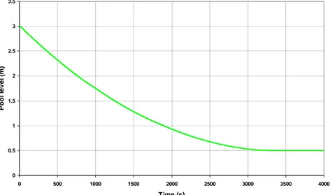
Figure 20 presents the trend of the liquid level, starting from 3 m at the beginning and decreasing down to the mean height of the outlet flow path, that as a height span of 1 cm on the containment side. The level trend is useful to understand the results obtained for the other variables, as it is in the case of containment pressure evaluated on Gothic side and transferred to RELAP5, shown in Figure 21; It can be noted that pressure oscillations
stacks of sub-volumes in the Gothic compartment, occurring when the level reaches 2 m and 1 m. 0 0.5 1 1.5 2 2.5 3 3.5 0 500 1000 1500 2000 2500 3000 3500 4000 Time (s) P o o l l evel ( m )
Figure 20. Sample case n. 3 – Pool level
9.00E+04 9.50E+04 1.00E+05 1.05E+05 1.10E+05 1.15E+05 1.20E+05 1.25E+05 1.30E+05 0 500 1000 1500 2000 2500 3000 3500 4000 4500 Time [s] P re ssu re [ P a ] p 210010000 (Pa) GOTHIC
Figure 21. Sample case n. 3 – Total atmosphere pressure
On the other hand, the additional oscillations observed in pressure, temperature flow rate (Figure 22 to Figure 26) after equalisation of pressures between primary system and containment are due to the explicitness of the numerical coupling between the codes, as already noted for previous calculation cases. These oscillations, that must be anyway expected, could be mitigated by decreasing the time step of the two codes. Except for the already noted slight difference in air temperature, the obtained results show the coherence of the procedure for transferring data between the two codes.
290.00 295.00 300.00 305.00 310.00 315.00 320.00 0 500 1000 1500 2000 2500 3000 3500 4000 Time [s] T e m p e r a tu re [ K ] tempg 110010000 (K) GOTHIC_TG
Figure 22. Sample case n. 3 – Atmosphere temperature
-180 -160 -140 -120 -100 -80 -60 -40 -20 0 20 40 0 500 1000 1500 2000 2500 3000 3500 4000 Time [s] L iq u id fl o w ra te [k g /s] mflowj liq 205000000 (kg/s) GOTHIC
Figure 23. Sample case n. 3 – Liquid mass flowrate
-0.40 -0.20 0.00 0.20 0.40 0.60 0.80 1.00 1.20 0 500 1000 1500 2000 2500 3000 3500 4000 Time [s] M a ss F low R a te [k g/ s] mflowj air 105000000 (kg/s) GOTHIC tot
290.00 295.00 300.00 305.00 310.00 315.00 320.00 0 500 1000 1500 2000 2500 3000 3500 4000 Time [s] T e m p e r a tu re [ K ] tempg 110010000 (K) GOTHIC_TG
Figure 25. Sample case n. 3 – Atmosphere temperature
310.0 310.5 311.0 311.5 312.0 312.5 313.0 313.5 314.0 314.5 315.0 0 500 1000 1500 2000 2500 3000 3500 4000 Time [s] T e m p e r a tu re [ K ] tempf 210010000 (K) GOTHIC_TF
Figure 26. Sample case n. 3 – Pool temperature
3.4 Pressurising a containment volume with air
3.4.1 Calculation case description
The aim of this test was to verify the correct transfer of a noncondensable gas (air) from the primary side to a volume of the containment system. The containment node has a free volume of 1000 m3 and the pressure and temperature of the atmosphere are 100000. Pa and 313.15 K, respectively. The volume initially contains only air (RH=0%) and is simulated using a lumped Gothic control volume linked to two RELAP5 piping branches (Figure 27). The opening trip of the valves in the upper piping branch is forced to be true after 10 s since the beginning of the test, while the valve in the lower piping branch is closed all along the transient. This causes a continuous injection of air at 313.15 K up to
the final pressure of 200000 Pa, with a configuration like that shown in the Figure 4-a. The coupling between the two codes is activated 5 s before the valve opening.
90 100 110 210 190 200 2x10⁵Pa V=1000 m3 p0=105Pa T0=313.15 K RH0=0% 195 105 95 205
Figure 27. RELAP5/Gothic model for the sample calculation n.4
3.4.2 Obtained results
Figure 28 shows the coincidence between the pressures evaluated by Gothic and calculated in RELAP5 at the time dependent volume 100. Also for this case, a slight difference in the air temperature values calculated by the two codes is observed in Figure 29, whose origin was already explained.
1.00E+05 1.20E+05 1.40E+05 1.60E+05 1.80E+05 2.00E+05 2.20E+05 2.40E+05 0 50 100 150 200 250 300 350 400 450 500 Time [s] P ressu re [P a ] p 110010000 (Pa) GOTHIC
310.0 320.0 330.0 340.0 350.0 360.0 370.0 380.0 0 100 200 300 400 500 Time [s] T e m p e r a tu re [ K ] tempg 210010000 (K) GOTHIC
Figure 29. Sample case n. 4 – Air temperature
Figure 30 and Figure 31 show the level of agreement in flow rate and specific enthalpy at the flow path injecting air into the Gothic volume; a perfect coincidence is noted for mass flow rate, while specific enthalpy shows a discrepancy at the start of the transient, before steady injection at a constant flow rate is reached. At the moment it is not possible to track the causes of such discrepancy due to the excursion noted in the variable plotted from Gothic, though it was ascertained that the temperature at the flow path is read correctly from RELAP5, as shown in Figure 32. So, at the moment it can be only suspected that the specific enthalpy of the mixture read at the Gothic junction is calculated incorrectly in the initial transient, though possibly not used in balances. This suspect should be confirmed in further analyses. 0.00 0.50 1.00 1.50 2.00 2.50 0 100 200 300 400 500 Time [s] M a ss F low R a te [k g/ s] mflowj air 105000000 (kg/s) GOTHIC
470000 470500 471000 471500 472000 472500 473000 473500 474000 0 100 200 300 400 500 Time [s] S p e c ifi c En th al p y [J/ k g] flenth / mflowj 95000000 (J/kg) GOTHIC
Figure 31. Sample case n. 4 – Inlet air specific enthalpy
310 311 312 313 314 315 316 317 318 319 320 0 50 100 150 200 250 300 350 400 450 500 Time [s] BC_ai r_ te m p er at ur e [ K ]
Figure 32. Sample case n. 4 – Inlet air temperature at the flow path in Gothic
3.5 Pressurising a containment volume with air and steam
3.5.1 Calculation case description
This sample calculation is similar to the previous one, but in this case an air/steam mixture at 200000. Pa and 373. K is injected into the containment system. Moreover, an initial saturated atmosphere is simulated (RH = 100%). The tank is again simulated using a lumped Gothic control volume linked to two RELAP5 piping branches (Figure 33).
The aim of this test was to verify the correct transfer of a steam/air mixture from the primary side to a containment volume. The trip valve allowing the steam/air inlet to the containment volume is opened after 10 s since the beginning of the test, while the coupling between the two codes is activated 5 s before the valve opening.
90 100 110 210 190 200 2x10⁵Pa T=373.15 X = 0.999999 V=1000 m3 p0=105Pa T0=313.15 K RH0=100% 195 105 95 205
Figure 33. RELAP5/Gothic model for the sample calculation n. 5
3.5.2 Obtained results
Figure 34 to Figure 37 report the results obtained in the analysis, showing the correct transfer of information between the two codes. The formation of liquid in the volume, allows to compare also the liquid temperature assigned on both sides of the information path. A slight discrepancy is noted in the partial flow rates of liquid and vapour that points out a limitation of the present coupling choices; in fact, the total flow rate of steam calculated by RELAP5 is translated in Gothic into a steam flow rate with a little quantity of liquid (Figure 37), as a consequence of the fact that the total pressure instead of the partial pressure of steam is assigned at the boundary condition.
This little problem, that becomes irrelevant if the noncondensable gases are absent or a sufficient amount of water accompanies steam, can be solved by a assigning an average pressure weighted on water and steam masses, on the basis of total and steam partial pressure. This choice has been implemented, but not fully tested though, as shown in Figure 38, it is very effective in mitigating the problem. The little consequences of the discrepancy observed for the present case suggest to postpone a careful analysis of such possible option to a future time.
100000.00 120000.00 140000.00 160000.00 180000.00 200000.00 220000.00 240000.00 0 100 200 300 400 500 Time [s] Pres su re [ K ] p 110010000 (Pa) GOTHIC
Figure 34. Sample case n. 5 – Total atmosphere pressure
290 310 330 350 370 390 410 0 100 200 300 400 500 Time [s] T e m p e r a tu re [ K ] tempf 110010000 (K) tempg 110010000 (K) GOTHIC GOTHIC
Figure 35. Sample case n. 5 – Atmosphere and pool temperature
0.80 0.82 0.84 0.86 0.88 0.90 0.92 0.94 0.96 0.98 1.00 0 100 200 300 400 500 Time [s] No nc o nde nsa b le m a ss f r a c ti o n [ -] quala 210010000 GOTHIC
0.00 0.10 0.20 0.30 0.40 0.50 0.60 0.70 0.80 0.90 1.00 0 100 200 300 400 500 Time [s] M a ss F lo w Ra te [ k g /s] mflowj liq 95000000 (kg/s) mflowj vap 95000000 (kg/s) mflowj air 95000000 (kg/s) GOTHIC gas GOTHIC vapour GOTHIC liq
Figure 37. Sample case n. 5 – Inlet steam, water and air mass flowrates
0.00 0.10 0.20 0.30 0.40 0.50 0.60 0.70 0.80 0.90 1.00 0 100 200 300 400 500 Time [s] M a ss F low R a te [k g/ s] mflowj liq 95000000 (kg/s) mflowj vap 95000000 (kg/s) mflowj air 95000000 (kg/s) GOTHIC gas GOTHIC vapour GOTHIC liq
Figure 38. Sample case n. 5 – Inlet steam, water and air mass flowrates with mass averaged pressure assigned to Gothic
3.6 Filling a containment volume with water
3.6.1 Calculation case description
This sample calculation is very similar to the previous ones, but now water at 40 °C is injected into the containment node. The aim of this test was to verify the correct transfer of water from the primary side (simulated with the RELAP5 code) to a containment volume (simulated by Gothic). The containment is still modelled using a lumped Gothic control volume linked to two RELAP5 piping branches (Figure 27). The opening trip of the valve in the lower piping branch is forced to be false, while the flow injected by the time dependent junction in the lower piping branch is assigned to zero, as shown in the Figure 4-a.
The trip valve allowing the inlet of water inside the containment volume is opened after 10 s since the beginning of the test, while the coupling between the two codes is activated 5 s before the valve opening.
3.6.2 Obtained results
Figure 39 and Figure 40 show the increase of pressure and gas temperature in the containment atmosphere pressure due air compression as a consequence of the increase of pool level, reported in Figure 41; on the other hand, the temperature of the pool, fed by water at a constant temperature and constant flow rate (Figure 42), does not change as soon as a pool level is formed and as long as it keeps increasing (Figure 41). As it can be noted in Figure 43, the noncondensable mass fraction in the atmosphere increases slightly as a consequence of condensation over the pool surface of the increasingly warm vapour.
9.00E+04 1.10E+05 1.30E+05 1.50E+05 1.70E+05 1.90E+05 2.10E+05 0 100 200 300 400 500 Time [s] P re ssu re [ P a ] p 210010000 (Pa) GOTHIC
Figure 39. Sample case n. 6 – Total atmosphere pressure
290 300 310 320 330 340 350 360 0 100 200 300 400 500 Time [s] T e m p e r a tu re [ K ] tempf 110010000 (K) tempg 110010000 (K) GOTHIC_TG GOTHIC_TF
0.00 0.50 1.00 1.50 2.00 2.50 3.00 3.50 4.00 4.50 5.00 0 50 100 150 200 250 300 350 400 450 500 Time (s) P o ol l eve l [ m ]
Figure 41. Sample case n. 6 – Pool level
0.00 100.00 200.00 300.00 400.00 500.00 600.00 700.00 800.00 900.00 1000.00 0 100 200 300 400 500 Time [s] M a ss F low R a te [k g/ s] mflowj liq 105000000 (kg/s) GOTHIC
Figure 42. Sample case n. 6 – Water mass flowrate
0.90 0.91 0.92 0.93 0.94 0.95 0.96 0.97 0.98 0.99 1.00 0 100 200 300 400 500 Time (s) N o n co n d en sa b le m a ss fr a ctio n ] quala 210010000 GOTHIC
3.7 Washing a containment volume with an air flow
3.7.1 Calculation case description
In this sample calculation, the washing of a large tank initially filled with pure air at a pressure of 100000 Pa and a temperature of 293.15 K is simulated. The washing is obtained by injecting hotter air (313.15 K) through the upper piping branch (Figure 44) at a specified rate, while air is allowed to exit through the lower piping branch. The aim of the test was to verify the correct transfer of a noncondensable gas from the primary system to a containment volume and viceversa, also checking that the right values of related energies contents are accounted for. The containment node has a free volume of 1000 m3 and is simulated using a lumped Gothic control volume, linked to two RELAP5 piping branches. The opening trip of the valves in the upper and lower piping branches are forced to be true after 10 s since the beginning of the test, so that a simultaneous injection and extraction of air is obtained, as shown in the Figure 4-c. The coupling between the two codes is activated 5 s before the valve opening.
90 100 110 210 190 200 105Pa 313.15 K V=1000 m3 p0=105Pa T0=293.15 K RH0=0% 195 105 95 205V-3 105Pa
Figure 44. RELAP5/Gothic model for the sample calculation n.7
3.7.2 Obtained results
As it can be noted from Figure 45 to Figure 48, the transient easily evolves towards an equalisation of the inlet and outlet air flows, with a complete washing of the atmosphere by air; the usual little discrepancy in air temperature is again observed.
1.00E+05 1.10E+05 1.20E+05 1.30E+05 1.40E+05 1.50E+05 1.60E+05 0 200 400 600 800 1000 1200 1400 1600 1800 2000 Time (s) P res su re ( P a ) p 110010000 (Pa) GOTHIC
Figure 45. Sample case n. 7 – Total atmosphere pressure
290.00 295.00 300.00 305.00 310.00 315.00 320.00 325.00 330.00 0 500 1000 1500 2000 Time [s] T e m p e r a tu re [ K ] tempg 110010000 (K) GOTHIC_TG
Figure 46. Sample case n. 7 – Atmosphere temperature
0.00 1.00 2.00 3.00 4.00 5.00 6.00 7.00 8.00 9.00 0 500 1000 1500 2000 Time [s] M a ss F low R a te [k g/ s] mflowj air 105000000 (kg/s) GOTHIC
-9.00 -8.00 -7.00 -6.00 -5.00 -4.00 -3.00 -2.00 -1.00 0.00 0 500 1000 1500 2000 Time [s] M a ss fl ow r a te [K g/ s] mflowj air 205000000 (kg/s) GOTHIC
Figure 48. Sample case n. 7 – Outlet air flowrate
3.8 Washing a containment volume with air and steam
3.8.1 Calculation case description
This sample calculation is very similar to the previous one, except for the initial content of steam in the atmosphere of the tank (RH = 100%) and the injection of noncondensable gases with saturated steam at the temperature 313.15 K. The tank is again simulated using a lumped Gothic control volume linked to two RELAP5 hydrodynamic piping branches (Figure 44). The opening trip of the valves in the upper and lower piping branches are forced to be true after 10 s since the beginning of the test, so that a simultaneous injection of air and extraction of water is obtained, as shown in the Figure 4-c. The coupling between the two codes is activated 5 s before the valve opening.
The aim of the test was to verify the correct transfer of a noncondensable gas and steam from the primary system to a containment volume and vice versa, also checking the right values of related energies contents are accounted for.
3.8.2 Obtained results
Figure 49 to Figure 53 show the main results obtained in this case, similar to those in the previous one, except for the trend of temperature in the volume that is affected by condensation of the suspended steam, with the subsequent release of latent heat.
1.00E+05 1.10E+05 1.20E+05 1.30E+05 1.40E+05 1.50E+05 1.60E+05 0 100 200 300 400 500 600 700 800 900 1000 Time [s] P re ssu re [ P a ] p 110010000 (Pa) GOTHIC
Figure 49. Sample case n. 8 – Total atmosphere pressure
275.00 280.00 285.00 290.00 295.00 300.00 305.00 310.00 315.00 320.00 325.00 330.00 0 200 400 600 800 1000 Time [s] T e m p era tu re [ K ] tempf 110010000 (K) tempg 110010000 (K) GOTHIC_TG GOTHIC_TF
Figure 50. Sample case n. 8 – Atmosphere temperature
0.950 0.955 0.960 0.965 0.970 0.975 0.980 0.985 0.990 0.995 1.000 1.005 0 200 400 600 800 1000 Time [s] G a s m a ss f r ac ti on [ -] quala 210010000 GOTHIC
0.00 1.00 2.00 3.00 4.00 5.00 6.00 7.00 8.00 0 200 400 600 800 1000 Time [s] M a ss F low R a te [k g/ s] mflowj vap 105000000 (kg/s) mflowj air 105000000 (kg/s) GOTHIC igas GOTHIC ist
Figure 52. Sample case n. 8 – Inlet mass flowrates
-9.00 -8.00 -7.00 -6.00 -5.00 -4.00 -3.00 -2.00 -1.00 0.00 1.00 0 200 400 600 800 1000 Time [s] M a ss F low R a te [k g/ s] mflowj tot 205000000 (kg/s) GOTHIC
Figure 53. Sample case n. 8 – Outlet mass flowrates
3.9 Vessel blowdown in a dry containment
3.9.1 Calculation case description
The sketch describing the topological arrangement of the problem was already described in Figure 5 and in detail in Figure 6a. The vessel is made of a stack of 20 RELAP5 volumes representing a component of 5 m in diameter and 12 m in height. The break pipe has a diameter of 0.5 m and a length of 1 m and is connected at the inlet of the 16th volume (from the bottom) representing the vessel, i.e. at an height of 9 m with respect to the bottom. The gravity driven line, having a diameter of 0.3 m and a length of 10 m is connected at the bottom of the vessel, though it is not activated in the present case. The two RELAP5 piping branches are connected to boundary conditions and flow paths located respectively at 9.5 m and 0.5 from the bottom of the containment, represented by a
lumped parameter Gothic containment having a volume of 70,000 m3. As previously mentioned, the trip valve simulating the break allows for the evaluation of critical flow. The vessel is initially full of water at 15.5 MPa with a specific internal energy of 1.4×10⁶
J/kg corresponding to a temperature of about 588 K (315 °C).
3.9.2 Obtained results
Figure 54 and Figure 58 show the classical scenario of a large break LOCA blowdown from a PWR primary system without ECCS intervention, including: the subcooled blowdown phase, liquid metastable effects and pressure recovery at flashing, break uncovery and faster depressurization, decreasing collapsed level in the vessel with final equalisation of pressures between primary system and containment (see also Figure 59).
0.00E+00 2.00E+06 4.00E+06 6.00E+06 8.00E+06 1.00E+07 1.20E+07 1.40E+07 1.60E+07 1.80E+07 0 500 1000 1500 2000 Time [s] P r e ssur e [ P a ] p 90010000 (Pa)
Figure 54. Sample case n. 9 – Primary system pressure
0.00E+00 2.00E+06 4.00E+06 6.00E+06 8.00E+06 1.00E+07 1.20E+07 1.40E+07 1.60E+07 1.80E+07 0 20 40 60 80 100 Time [s] P r e ssur e [ P a ] p 90010000 (Pa)
0 2000 4000 6000 8000 10000 12000 0 100 200 300 400 500 Time [s] B rea k a n d Gr a v it y D r iv en Flo w R a te [ k g /s ] mflowj 105000000 (kg/sec) mflowj 205000000 (kg/sec)
Figure 56. Sample case n. 9 – Total break mass flowrate
300 350 400 450 500 550 600 650 0 100 200 300 400 500 Time [s] T e m p e r a tu re [ K ] tempf 90200000 (K) tempg 90200000 (K) tempf 90160000 (K) tempg 90160000 (K)
Figure 57. Sample case n. 9 – Primary system temperature
0 1 2 3 4 5 6 7 8 9 10 11 12 0 100 200 300 400 500 Time [s] V e ss el C o ll a p se d L e v e l [ m ]
0 50000 100000 150000 200000 250000 300000 350000 0 200 400 600 800 1000 Time [s] Pres su re [ P a ]
Figure 59. Sample case n. 9 – Containment pressure
0 2000 4000 6000 8000 10000 12000 0 50 100 150 200 Time [s] M a ss F low R a te [k g/ s] mflowj liq 105000000 (kg/s) mflowj vap 105000000 (kg/s) GOTHIC isteam GOTHIC iwat
Figure 60. Sample case n. 9 – Break flowrate comparison
The break flow rate liquid and vapour components are compared in Figure 60 as calculated by RELAP5 and Gothic; the very good match of the two components testifies that the codes interpret in a same way the enthalpy assigned to the flow.
300 320 340 360 380 400 420 440 460 0 100 200 300 400 500 600 700 800 900 1000 Time (s) Tem p er at ur e ( K ) GOTHIC_TG GOTHIC_TF
Figure 61. Sample case n. 9 – Atmosphere and pool containment temperatures
0 10000 20000 30000 40000 50000 60000 70000 0 100 200 300 400 500 600 700 800 900 1000 Time (s) P o ol m a s s ( K g)
Figure 62. Sample case n. 9 – Containment pool mass
Finally, the containment pool and atmosphere temperatures and the pool mass follow trends that are fully expected (Figure 61 and Figure 62).
3.10 Vessel blowdown in a containment with gravity driven injection
3.10.1 Calculation case description
• the containment volume, having the same overall size as in the previous case (70,000 m3), has now a height of 50 m and is filled with 7 m of water at 40 °C;
• the containment volume is now subdivided into several vertical subvolumes, in order to allow for the calculation of the pressure head due to the containment level above the gravity driven injection pipe (Figure 63);
• the trip valve in the lower piping branch is now activated, making it have a role of gravity driven injection, thanks to the forward form loss coefficients of 10100 assigned to the trip valve.
The main aim of this analysis is to demonstrate the functional capability of the coupled code to simulate a simultaneous blowdown and a passive ECCS injection scenario.
3.10.2 Obtained results
As the main short term phenomena on primary side are similar to the ones shown for the previous case, attention will be now concentrated on the effect of triggering the gravity driven injection. In fact, as shown in Figure 64, the break flow rate trends have little difference with respect to the previous case.
-2000 0 2000 4000 6000 8000 10000 12000 0 50 100 150 200 Time [s] M a ss F low R a te [k g/ s] mflowj liq 105000000 (kg/s) mflowj vap 105000000 (kg/s) GOTHIC isteam GOTHIC iwat
Figure 64. Sample case n. 9 – Break flowrate comparison Figure 63. Sample case n. 10:
In this case, after reaching a sufficient equalization between primary and containment pressure, gravity driven injection from containment to the vessel occurs (Figure 65), recovering the vessel water inventory. It can be noted that the levels reached in the vessel and in the containment differ of a quantity close to the height difference of 0.5 m of the lower piping branch in the primary and in the containment systems (Figure 66 and
Figure 67). -500 -400 -300 -200 -100 0 100 0 500 1000 1500 2000 Time [s] M a ss F low R a te [k g/ s] mflowj liq 205000000 (kg/s) GOTHIC
Figure 65. Sample case n. 10 – Gravity driven injection flow rate
0 1 2 3 4 5 6 7 8 9 10 11 12 13 0 100 200 300 400 500 Time [s] Ve sse l Co ll a p se d L e v e l [ m ]
Figure 66. Sample case n. 10 – Vessel collapsed level
GOTHIC lev 6.98 6.99 7 7.01 7.02 7.03 7.04 7.05 7.06 0 100 200 300 400 500 600 Time (s) Po ol l eve l (m )
4. CONCLUSIONS
The results obtained from the calculation cases presented in this document support the substantial adequacy of the work performed in coupling RELAP5 and Gothic.
Though different aspects of the adopted coupling methodology may need further refinements, as also mentioned in the Introduction, the results that were obtained confirm the suitability the general adopted strategy.
In selecting validation cases, the attention was mainly focused on confirming that the exchanges between the two codes are correct. This was the reason why essential RELAP5 nodalizations were selected, mainly referring to pipes injecting or extracting fluid to or from a containment volume. It is clear that a whatever complex RELAP5 nodalisation can be linked in a similar way to a Gothic multiple volume model, obtaining a similar quality in the exchange of data.
The final calculation cases addressing a pressurised water vessel blowdown served to show the suitability of the obtained coupling methodology to deal with a classical safety relevant calculation case.
Though running the sample cases did not encounter severe difficulties, it has to be expected that the robustness of the coupling will increase with the use of the model and with the introduction of numerical recipes necessary to deal with possible encountered exceptions in dealing with variable transfer from one code to the other. The explicit character of the adopted coupling (the only possible without intruding in the structure of the two codes) has shown limitations in the presence of oscillations occurring when the primary system and the containment pressures are very close, pointing out effects which can be fully expected considering the need for pressure-velocity coupling algorithms widely adopted in fluid-dynamics.
In summary, the work performed up to now represents what it was feasible to achieve with the available code versions and their characteristics in terms of variable accessibility. Further code versions making available more information on junction and flow path variables might lead to a better and more accurate strategy for coupling the two codes.
REFERENCES
[1] Walter Ambrosini, Antonio Manfredini, Methodology for coupling thermal-hydraulic codes for primary system and containment analysis, Università di Pisa, DIMNP RL 1286(2011), August, 2011.
[2] RELAP5/MOD3.3 CODE MANUAL, VOLUME I: CODE STRUCTURE, SYSTEM MODELS, AND SOLUTION METHODS, Nuclear Safety Analysis Division, December 2001, Information Systems Laboratories, Inc., Rockville, Maryland, Idaho Falls, Idaho, Prepared for the Division of Systems Research Office of Nuclear Regulatory Research, U. S. Nuclear Regulatory Commission, Washington, DC 20555, NUREG/CR-5535/Rev 1-Vol I.
[3] RELAP5/MOD3.3 CODE MANUAL, VOLUME II, APPENDIX A, INPUT
REQUIREMENTS, Nuclear Safety Analysis Division, January 2002, Information Systems Laboratories, Inc., Rockville, Maryland, Idaho Falls, Idaho, NUREG/CR-5535/Rev 1-Vol II App A.
[4] T. George, S. Claybrook, L. Wiles, C. Wheeler, Gothic, CONTAINMENT ANALYSIS PACKAGE USER MANUAL, Version 7.2b(QA), NAI 8907-02 Rev 18, March 2009.