LIQUID FILTRATION THROUGH
CERAMIC MEMBRANES
D. DE MEIS Dipartimento Fusione e Tecnologie per la Sicurezza Nucleare Divisione Fisica della Fusione Laboratorio Sorgenti,Antenne e Diagnostica Centro Ricerche Frascati,Roma
RT/2017/8/ENEA
ITALIAN NATIONAL AGENCY FOR NEW TECHNOLOGIES, ENERGY AND SUSTAINABLE ECONOMIC DEVELOPMENT
D. DE MEIS Dipartimento Fusione e Tecnologie per la Sicurezza Nucleare Divisione Fisica della Fusione Laboratorio Sorgenti, Antenne e Diagnostica Centro Ricerche Frascati, Roma
LIQUID FILTRATION THROUGH
CERAMIC MEMBRANES
RT/2017/8/ENEA
ITALIAN NATIONAL AGENCY FOR NEW TECHNOLOGIES, ENERGY AND SUSTAINABLE ECONOMIC DEVELOPMENT
I rapporti tecnici sono scaricabili in formato pdf dal sito web ENEA alla pagina http://www.enea.it/it/produzione-scientifica/rapporti-tecnici
I contenuti tecnico-scientifici dei rapporti tecnici dell’ENEA rispecchiano l’opinione degli autori e non necessariamente quella dell’Agenzia
The technical and scientific contents of these reports express the opinion of the authors but not necessarily the opinion of ENEA.
LIQUID FILTRATION TROUGH CERAMIC MEMBRANES D. De Meis
Riassunto
Da molto tempo le membrane ceramiche, utilizzate principalmente nella configurazione a singolo o a multi canale, costituiscono una tecnologia per la separazione di solidi disciolti o di ioni nei liquidi in condizioni difficili.
Le membrane ceramiche per la filtrazione dei liquidi appartengono alla famiglia delle ossido mem-brane di ceramica e sono principalmente realizzate di ossido di alluminio, ossido di zirconio o ossido di titanio.
I processi di filtrazione a membrana guidati dalla pressione, cioè microfiltrazione (MF), ultrafiltrazione (UF), nanofiltrazione (NF) e osmosi inversa (RO), facilitano la separazione dei componenti con una vasta gamma di dimensioni delle particelle.
Due approcci sono utilizzati per descrivere la permeabilità attraverso membrane porose. Quando la membrana assomiglia ad un arrangiamento di particelle quasi sferiche può essere applicata l'equazione di Carman-Kozeny per determinare il flusso del permeato. Quando i pori della membrana sono consi-derati cilindrici si applica la ben nota legge di Hagen-Poiseuille per calcolare il flusso di permeato di fluido laminare.
Parole chiave: filtrazione di liquido, membrane ceramiche, trasporto convettivo, equazione di Car-man-Kozeny, equazione di Hagen-Poiseuille
Abstract
Since long time ceramic membranes, mainly used in single-channel or in multi-channel design, are an established process for the separation of dissolved solids or ions out of liquids under rough condi-tions.
Ceramic membranes for liquid filtration belong to the oxide ceramic membranes and are mainly made of aluminium oxide, zirconium oxide or titanium oxide.
Pressure driven membrane processes, namely microfiltration (MF), ultrafiltration (UF), nanofiltration (NF) and reverse osmosis (RO), facilitate separation of components with a large range of particle sizes. Two approaches are utilized for describing permeability through porous membranes. When the mem-brane resembles an arrangement of near-spherical particles the Carman–Kozeny equation can be ap-plied to determine the permeate flux. When the membrane porous are considered cylindrical the well-known Hagen-Poiseuille equation applies to calculate the laminar fluid flow permeate flux. Keywords: liquid filtration, ceramic membranes, convective transport, Carman-Kozeny equation, Hagen-Poiseuille equation
1. Introduction
2. Ceramic membranes for liquid filtration 3. Pressure driven membrane processes 4. Driving forces for transport mechanisms
5. Convective transport through a porous membrane layer
6. Mass transfer resistances in membrane separation process of liquids Acknowledgments References 7 7 9 11 12 14 16 16
INDEX
7
Liquid filtration through ceramic membranes
1. Introduction
Polymeric, composite and inorganic membranes are typically used for liquid filtration. Ceramic membranes belong to the group of inorganic porous membranes. Since long time ceramic membranes are an established process for the separation dissolved solids or ions out of liquids under rough conditions. Due to constant improvements in materials and production methods, it is possible to replace established processes like e.g. evaporators by these membranes with lower investment and running costs without any disadvantages in product quality or efficiency.
The use of membrane technology in food industry, dairy applications and for industrial needs is gaining wide application.
Membrane filtration to remove microorganisms for shelf-life extension of foods instead of using additives and preservatives gives a green image.
The recovery of valuable components in diluted effluents and wastewater treatment applications are among the most useful and currently active aspects of membrane technology.
Pressure driven membrane processes, namely microfiltration (MF), ultrafiltration (UF), nanofiltration (NF) and reverse osmosis (RO), facilitate separation of components with a large range of particle sizes. It is for this reason that they find wide range of applications in food processing industry.
This paper gives an overview about the theory of liquid filtration trough ceramic membranes.
2. Ceramic membranes for liquid filtration
Ceramic membranes for liquid filtration belong to the oxide ceramic membranes and are mainly made of aluminium oxide, zirconium oxide or titanium oxide. Compared with other typical membranes for liquid filtration, ceramic membranes provide a lot of advantages:
- high chemical resistance (pH-value 0–14), - high thermal resistance,
-high resistance against biological and microorganism, -high resistance against abrasive media,
-easy handling and storage.
Ceramic membranes can be fixed on flat sheet supports as well as on tubular or multitubular supports. The flat sheet design is mainly used for lab applications; for industrial applications the usual design for ceramic
8
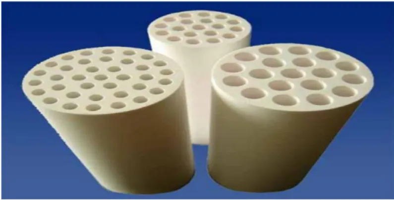
membranes is tubular. Depending on the application and properties like e.g. viscosity and particle content, they are used in single-channel design or in multi-channel design (see fig. 1).
Fig. 1 Multi channel ceramic membranes (Manohar 2012)
The diameter of the tubes varies from 10-180 mm. In some cases the tube diameter will be 6, 9.6, 12, 16, 19 and 25 mm.
Membrane layers are fixed on the support, starting with very coarse layers – so called intermediate layers; membrane layers with decreasing pore sizes are added until the designated pore sizes are reached. Fig. 2 shows a typical structure of different layers (Duscher 2013).
Fig. 2 Ceramic membrane typical structure
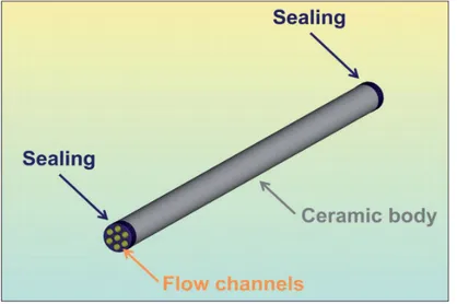
The membrane layer in standard ceramic filter is fixed at the inside of the tubes (see fig. 3).
.
9
The faces sides of the ceramic filter elements are sealed to avoid that feed or concentrate can by-pass the membrane.
Fig. 4 shows the components of a ceramic filter element.
Fig. 4 Components of ceramic filter (Duscher 2013)
Feed liquid flows through the tubular channels pressurized by a feed pump. Ceramic filter elements are installed in housings (fig. 5).
10
3. Pressure driven membrane processes
The pressure driven membrane processes include microfiltration (MF), ultrafiltration (UF), nanofiltration (NF), and reverse osmosis (RO).
When a feed stream is introduced to a membrane it is separated into retentate (sometimes called concentrate), the fraction that is retained by the membrane, and permeate (also called filtrate), the fraction that passes through the membrane (fig. 6).
Fig. 6 Cross flow filtration (Spx 2013)
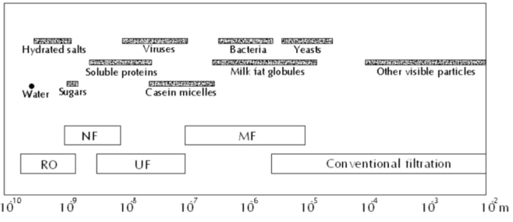
The word ‘pressure driven’ means that the main driving force for separation of these processes is transmembrane pressure (TMP), which is the pressure discrepancy between retentate sides and permeate side. Generally speaking, the pore sizes (or MWCO - molecular weight cut-off in cases of NF and RO) of membranes decrease in the order from MF to RO (fig 7). However, the separation principle is not based on the pore sizes alone. Especially in UF and NF the charge of the molecules/solutes and their affinity for the filtering membrane are also important (Le 2014, Il Latte 2014, Duscher 2014).
11 MF is normally used for separation of suspended particles and microorganisms from soluble components in feed. UF can be applied to separate soluble macromolecules such as proteins and peptides. NF is applied for partial demineralization and, at the same time, concentration.
Operational TMP values increase from MF to RO. For example, in MF applications the applied TMP is rarely higher than 3 bar. While those for UF are normally in range of 3-7 bar and for NF 10-30 bar. The operational TMP applied in RO is normally much higher (e.g., 10-75 bar) than in other pressure-driven separation processes.
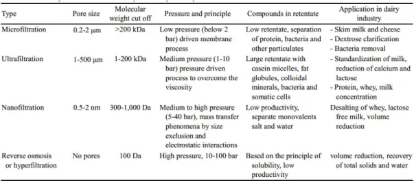
Table 1 reports various types of membrane with different properties available and used in the dairy industry.
Tab. 1 Common used membrane in dairy industry (Kumar 2013)
4. Driving forces for transport mechanisms
Membrane filtration can be a very efficient and economical way of separating components that are suspended or dissolved in a liquid.
The membrane is a physical barrier that allows certain compounds to pass through, depending on their physical and/or chemical properties. Membranes commonly consist of a porous support layer with a thin dense layer on top that forms the actual membrane.
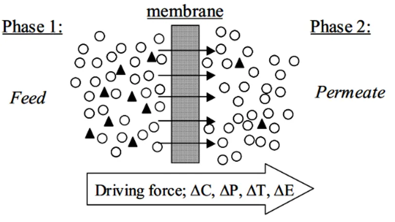
The separation process and mass transport through the membranes is a function of the membrane being used and the constituents separated. Common for all systems is the principle illustrated in fig. 8 where the membrane is a permeselective barrier and the separation process takes place due to a specific driving force.
12
Fig. 8 Different driving forces present in a membrane separation process
The selectivity of a membrane is expressed by separation factor (α ) defined with the following formula:
α = େౚିେ౦౨ౣ౪ େౚ
For binary mixture of components A and B, the separation factor is expressed by the concentrations in the feed Xa X B and permeate (YA and YB) as the following formula:
The driving force is generally determined by the difference in chemical potential and is a result of either pressure differences across the membrane, concentration gradients of the two phases or from temperature differences (Leiknes 2001).
5. Convective transport through a porous membrane layer
Pressure-driven convective flow is most commonly used to describe the flow in capillary tubes. The key mechanism at the core of both microfiltration and ultrafiltration is the sieving process.
Two approaches are utilized for describing permeability through porous membranes.
In the first case, when the membrane resembles an arrangement of near-spherical particles (for example spongy or sintered particle structure, see fig. 9), then the Carman–Kozeny equation can be applied, as illustrated in the following equation (Abdelrasoul 2015):
13
where J is the permeate flux (l mିଶ hିଵ)
Fig. 9 Spheres geometry of porous membrane
Both K and S depend upon the nature of the membrane porous structure. The permeability constant, K , is a function of the membrane structure, including characteristics such as pore size distribution, and porosity of the membrane, as well as the viscosity of the permeate (for ceramic membrane K= 13).
In the second approach, the laminar fluid flow through the capillaries can be described by means of the differential momentum balance equation, Newton’s law of viscosity . After integration, the well-known Hagen-Poiseuille equation for the average convective velocity through the porous membrane (porous considered cylindrical, see fig. 10) was obtained to calculate the permeate flux, as described by the following equation (Abdelrasoul 2015):
14
Fig. 10 Cylindrical geometry of porous membrane
Again the flux is inversely proportional to the viscosity of the permeate.
6. Mass transfer resistances in membrane separation process of liquids
For the porous medium Darcy law is the basic equation that can be utilized in order to describe the rate of fluid flow, as showed in the following equation (Abdelrasoul 2015):
where Q is the total discharge, (m³ݏିଵ), k (mଶ) is the empirical constant representing permeability of the medium, (A) (mଶ) is the cross-sectional area to flow, (ܲ − ܲ) is the pressure drop, µ (kg mିଵsିଵ or
Pa s) is the viscosity, and L (m) is the membrane thickness.
15 where ܴ is the resistance of the membrane and ܴ is the resistance, which arises due to membrane fouling (that is a gradual decline in permeate flow through the membrane). Membrane resistance can be expressed as:
where ∆P்ெ is transmembrane pressure, J is density of the permeate flux and µ is dynamic viscosity.
Additional resistance of the membrane, which arises from fouling, can be expressed as:
where ∆P்ெ is transmembrane pressure, J is density of the permeate flux, µ is dynamic viscosity and ܴ is the resistance of the membrane.
16
Acknowledgments
I thanks you all colleagues for their help and support. In particular I would like to express my sincere gratitude to ing. Silvano Tosti for the his continuous support, patience, motivation and enthusiasm.
References
Manohar, “Development & characterization of Ceramic membranes”, IJMER, July-Aug. 2012 S. Ducher, “Ceramic membranes in chemical and pharmaceutical applications”, Inopor, 2013 SPX, Removal of bacteria and spores from milk, using membrane filtration, white paper, 2013
T. T. Le, “Membrane separations in dairy processing”, Journal of food research and technology, January-march 2014
La separazione mediante filtrazione a membrane, dossier, Rivista Il latte, gennaio 2014
St. Duscher, Ceramic membranes for the filtration of liquids: an actual review, F&S International edition, n° 14/2014
P. Kumar et alii, Perspective of membrane thechnology in dairy industry: a review, Asian-Australasian journal of animal sciences, 2013
T. Leiknes, “Transfer and Degassing Using Hollow Fiber Membranes”, PHD Thesis , NTNU-Norway, December, 2001. ISBN 82-471-5391-2
A. Abdelrasoul et alii “ Mass transfer mechanisms and transport resistances in membrane separation process”, chapter 2, 2015, http://dx.doi.org/10.5772/60866
M. Smorada et alii, “Effect of pressure gradient on the membrane separation in ceramic microfiltration membrane – FCCR”, Annalis of faculty engineering Hunedoara, 2012
ENEA
Servizio Promozione e Comunicazione
www.enea.it
Stampa: Laboratorio Tecnografico ENEA - C.R. Frascati aprile 2017