POLITECNICO DI MILANO
Corso di Laurea Magistrale in Ingegneria Informatica Dipartimento di Elettronica, Informazione e Bioingegneria
A Network Interface Design for
Networks-on-Chip in Heterogeneous
NUMA Multicores
Relatore: Prof. William Fornaciari Correlatore: Dr. Davide Zoni
Tesi di Laurea di: Luca Borghese, 800606
Abstract
The multi-core revolution push to the limit the need for a fresh interconnect and memory design to deliver architectures that can match current and future application requirements. Moreover, the current trend towards multi-node multi-core architectures to further improve the system performance impose the use of hierarchical and eventually heterogeneous interconnection subsystems.
In this scenario the Network Interface (NI) controller represents a critical component to allow an easy efficient and effective link between the cores and the memory blocks to the interconnect. Moreover, the buffers and the pipeline stages of the NI must be carefully evaluated not to waste valuable on-chip resources.
The thesis explores the NI design in the multi-core multi-node architec-tures, with particular emphasis on the timing and performance metric. An NI design developed in RTL Verilog is used to analyze the timing metric and is used as a basis to develop a cycle accurate software simulation model that has been integrated into GEM5 multi-core cycle accurate simulator. Simulation results show the benefit of the proposed NI model from the re-sult accuracy viewpoint. In particular, our NI model demonstrates how the baseline NI GEM5 model overestimates the performance of the simulated architectures mainly due to the avoid of the contention between the cores in the same node to access the on-node bus interconnect. Moreover, presented results highlight the modest and linear (with the number of pipeline stages) impact due to the NI considering different number of stages.
Contents
1 Introduction 1
1.1 The Importance of the NI in the Multi-Node Multi-Cores . . 2
1.2 The Goal of the Thesis and Spot Considerations . . . 2
1.3 Backgrounds . . . 3
1.4 The Thesis Structure . . . 7
2 State of the Art 9 2.1 Bridging Different Interconnects in Multi-Node Multi-Cores . 9 2.2 The NI as a Particular Bridge . . . 10
2.3 NI Model in Software Simulators . . . 12
3 The NI Architecture Design: from the RTL to the Software Simulation Model 13 3.1 Architectural View . . . 13
3.1.1 The Input Port Architecture . . . 14
3.1.2 The Message Queue Architecture . . . 16
3.1.3 The WISHBONE Wrapper Architecture . . . 16
3.1.4 The Packet Buffer Architecture . . . 18
3.1.5 The Virtual Channel Allocator Architecture . . . 18
3.1.6 The Link Allocator Architecture . . . 18
3.2 RTL Modules . . . 18
3.3 An NI Software Implementation Integrated into GEM5 . . . . 19
4 Results 21 4.1 Simulation Setup . . . 21
4.1.1 Synthetic Traffic Setup . . . 22
4.1.2 Real Benchmark Setup . . . 23
4.2 Timing Results . . . 24
4.3 Synthetic Traffic Results . . . 25
4.4.1 A Low Contention System Case . . . 32 4.4.2 An High Contention System Case . . . 32
5 Conclusions and Future Works 37
5.1 Future Works . . . 38
List of Figures
1.1 NI models comparison in GEM5 . . . 3
1.2 A multi-core based on NoC interconnect . . . 4
1.3 NoC message structure . . . 5
1.4 The baseline router architecture . . . 6
1.5 The baseline router pipeline . . . 6
3.1 NI architecture . . . 15
3.2 NI NoC-to-Node three stages pipeline . . . 15
3.3 NI Node-to-NoC four stages pipeline . . . 15
3.4 Wrappers architecture . . . 17
3.5 Verilog modules inclusion . . . 19
3.6 GEM5 simulated architecture . . . 20
4.1 Average packet latency synthetic traffic with data packet size of one flit . . . 27
4.2 Average packet latency synthetic traffic with data packet size of three flits . . . 28
4.3 Average packet latency synthetic traffic different packet size . 29 4.4 Average packet latency synthetic traffic in a 2x2 2D-mesh . . 30
4.5 mibench applications average injection rate . . . 31
4.6 mibench applications execution time overhead per core . . . . 33
4.7 mibench applications execution time overhead per NI model . 34 4.8 mibench applications execution time overhead in a system with high contention . . . 35
List of Tables
4.1 Alias table . . . 22 4.2 Experimental setup . . . 23 4.3 mibench applications used with parameters configuration . . . 24 4.4 Pipeline stages clock period . . . 25 4.5 NI designs clock period evaluation . . . 25
Chapter 1
Introduction
During the last ten years, multi-core architectures emerged as the de-facto solution to satisfy the performance requirements of modern applications. Their versatility makes them suitable in different areas ranging from em-bedded up to high performance computing (HPC) architectures. In partic-ular, the great diffusion of portable devices with low power requirements exploits the Multi-Processor System-on-Chip (MPSoC) architectures to op-timize their power-performance trade-off. Nowadays, the heterogeneous multi-cores [27] composed of in-order and out-of-order cores as well as GPU in the same SoC, represent the de-facto standard for hand-held devices due to their better suitability to match the applications requirements.
The increase number of cores requires an enormous bandwidth capacity and stringent latency requirements, making the use of bus-based intercon-nection infeasible. Networks-on-Chips (NoCs) [13, 3] represent the widely accepted solution to connect multiple cores, due to its scalability, flexibility and high bandwidth properties. However, bus-based architectures can pro-vide better performance when used in multi-cores with a limited number of cores. Moreover, the interconnect greatly impacts the total chip power [18], thus encouraging several ad-hoc optimizations.
However, an IP block usually does not fully exploit the bandwidth offered by a NoC, so multi-node multi-core architectures have been introduced. In this architectures, the cores are connected using a hierarchical interconnec-tion fabric composed of a possibly heterogeneous inter-node and an intra-node pair of interconnects. The expectations on these architectures are high, but the research is still at its infancy. There aren’t suitable tools that are flexible enough to make a design space exploration of this huge family.
A critical component in the interconnect design is the Network Interface (NI) controller, that implements the necessary logic to interface the IP blocks
with the underlined communication architecture from both the hardware and protocol viewpoints. In particular, the NI organizes the access to the shared interconnect by each IP block, also providing a decoupling temporal storage buffer without blocking the IP computation when the interconnect is congested. Thus, the NI plays a critical role from the timing, power and performance of the entire multi-core while accurate balance of allocated resource in the NI is required to constraint its area.
1.1
The Importance of the NI in the Multi-Node
Multi-Cores
The rapid introduction of the multi-core multi-node architectures requires proper NI designs to interface two different interconnects in the same chip, rather than a single IP block to the interconnect. This component has a great impact on the overall interconnection system and its design is crucial. In order to evaluate this emerging multi-core multi-node is important to have an accurate model of the NI which allows the extraction of accurate information.
Figure 1.1 shows the performance overhead, evaluated using the GEM51
simulator [5, 20], introducing an accurate NI software model instead of using the baseline model in a NoC based multi-core. With this simulation errors a good exploration of multi-node multi-cores is not possible.
1.2
The Goal of the Thesis and Spot
Considera-tions
Considering the current trend towards multi-node multi-core architectures and the critical rule the interconnect plays in the whole system, the thesis fo-cuses on an accurate NI design accounting for both timing and performance metrics with two main objectives. First, the timing metric is evaluated start-ing from a proposed RTL NI model. In particular, different parameters in the NI design have been explored, i.e. number of stages, different allocated resources etc. Second, a software simulation model of the proposed RTL NI has been integrated into the GEM5 performance simulator to be exploited by the research community to provide more accurate results. The proposed results in the rest of the thesis highlight the need for a more accurate NI model with respect to the one actually integrated in the software simulator
1
Figure 1.1: Comparison Between the vanilla NI Models of GEM5 with a more accurate developed one.
to better validate the multi-node multi-core architectures. In particular, different design of the proposed NI model have been studied considering an hybrid interconnection scheme, where a bus is used to connects cores inside each node, while an NoC connects the nodes.
The proposed results show how the tremendous impact of the inter-node bus contention represents the first overhead source, while the overhead due to a deeper NI pipeline marginally affects the performance results. On the other hand providing a deeper pipeline allows to greatly improve the operating frequency of the NI. For example a single cycle NI design decreases the operating frequency up to 66% with respect to a four cycle one.
1.3
Backgrounds
A Network-on-Chip is a scalable and reliable interconnect that allows nodes to exchange data. A node can be both a CPU or a part of the memory subsystem. The NoC is composed by routers, links and Network Interface Controllers (NICs).
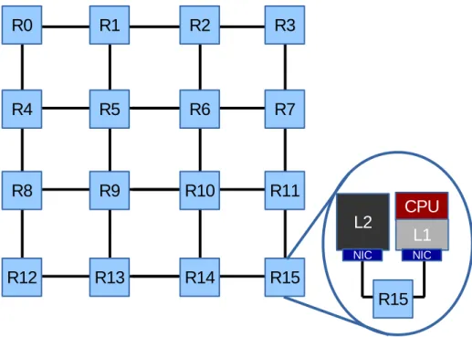
Figure 1.2 shows an MPSoC with an NoC based interconnect. The de-picted NoC has a 4x4 2D-mesh topology. Each node is connected to the local router via NIC, which allows the communication between a node and a router. Routers routes data, injected by nodes, into the network. Links connect two adjacent routers or a router and a NIC.
The NoC divides node’s messages in packets, and splits these packets in flits. Flits are used to better utilize the NoC resources. These different granularity are shown in Figure 1.3. The packet packaging and un-packaging task is performed by the NIC. A packet is composed of different types of flits. The head flit is the first part of a packet, the body flit is an intermediate chunk of a packet and the tail flit is the last part. If a packet is composed of only one flit it is called head/tail flit.
Figure 1.2: A multi-core based on NoC interconnect. It is pictured a 4x4 2D-mesh NoC. In detail the connection between a node and a router through an NI
The NoC is characterized by: the layout topology, the routing scheme, the switching mechanism, the flow control mechanism and the router archi-tecture.
The NoC topology defines how the links connect routers to each others and to nodes. The most common topologies are mesh [9], concentrated mesh [2], hybrid bus based [25] and high radix [15]. 2D-mesh topology is the most used due to its facilitated implementation. An example of a 2D-mesh is shown in Figure 1.2.
The routing scheme determines the path of a packet inside the NoC from a source node to a destination node. If the path for a source-destination pair is fixed, the routing scheme is called deterministic [2]. Otherwise, if the path can be altered, the routing scheme is called adaptive [11, 10].
Figure 1.3: Message structure in NoC. Messages are divided in packets and, furthermore, in flits.
The switching mechanism defines how a router forwards the received packets to the next hop, a router or a node. Some switching mechanism are Store-and-Forward [17], Virtual cut-Through [16], Wormhole switching [19] and Virtual-Channel Wormhole switching [8]. The latter technique is the most used one.
The flow control mechanism are used by routers to control the available storage resources of adjacent hops. A router has to stop the transmission of a packet if the downstream router is out of buffers. Three mechanism are used: Credit-based, Stop & Go and Ack/Nack [9].
A detailed description of the used NoC is given in the rest of this section. Figure 1.4 shows a wormhole router architecture that supports virtual chan-nels (VC) and virtual networks (VNET). The VNET support allows dead-lock avoidance in coherence protocol. It has four internal pipeline stages, i.e. Buffer Write/Route Computation (BW/RC), Virtual Channel Alloca-tion (VA), Switch AllocaAlloca-tion (SA), and Switch Traversal (ST). The Link Traversal (LT) stage is executed outside the router and is assumed to be one cycle. Figure 1.5 shows the router’s pipeline stages. When a new flit is transmitted by the upstream router, it is stored in a reserved VC buffer (BW) and the output port is computed (RC). In the VA stage an idle VC
buffer of the output port is reserved for its transmission. Note that only the head flit needs the RC and VA stage. All the other flits inherit the output port and the VC buffer from the head flit. In the Switch Allocation stage an arbiter decides which flits, stored in the input ports with a VC allocated, can pass the crossbar in the next cycle. If the flit won the SA stage, it passes the crossbar in the ST stage and reaches the downstream router after the LT stage.
Figure 1.4: The baseline router architecture. The figure shows a virtual-channel, worm-hole, credit-based router and its main components.
Figure 1.5: The baseline router pipeline.
The NIC allows the communication between a node and a router. A message received by the node is packaged and flitisized. After that a VC is allocated for the packet’s flits and then they are sent over the link. On
the other hand when it receives an entire packet from a router, the tail flit arrives, the message is reconstructed and sent to the attached node.
1.4
The Thesis Structure
The rest of thesis is organized in four chapters. Chapter 2 describes the state of the art of NI design. Chapter 3 provides the architecture and software model of the proposed NI controller. Chapter 4 shows the results of the design space exploration with synthetic and real application traffic. Chapter 5 discusses the final benefits of the proposed NI model as well as the possible future works and optimizations.
Chapter 2
State of the Art
NI design is important in the interconnection system of MPSoC. In [23], a TV companion chip was redesigned with a NoC as interconnect, and 78% of increase in chip area was proved to come from the NIs. Similar case, in the xpipes based system in [1], more than half of the NoC area is due to NIs.
Despite this NI design doesn’t receive a lot of attention in the litera-ture, since the support for processing cores with advanced communication capabilities (e.g., multiple outstanding transactions, out-of-order comple-tion, quality of service guarantees) requires complex architectures with a restricted margin for optimization.
2.1
Bridging Different Interconnects in Multi-Node
Multi-Cores
Paul Wielage and Kees Goossens [26] proposed to investigate hybrid ar-chitecture with first-level communication over a shared-medium, and the higher levels using a packet-switched network. This can bring several bene-fits. First, a single IP connected can underutilize the bandwidth capacity of an individual router port. Second, Network Interfaces are more expensive (in terms of area) than, for example, a bus adaptor.
The strong of resource sharing has been proved in [12], where sharing an NI between several nodes significantly reduced the area overhead of the NoC with low performance overhead in terms of execution cycles. The ar-chitecture consist in an arbiter placed between the processing elements and the Network Interface.
To ensure the reusability of existing IPs, given the great diffusion of bus-based architectures, many people proposed interconnection systems that expose a bus-like protocol. This not only improve the flexibility of the
archi-tecture, but also reduces the time-to-market allowing a faster development. In [22], an existing NoC has been extended to support WISHBONE Inter-connection architecture, so it can be used in many SoC designs based on the WISHBONE interface. Furthermore, they use an FPGA devices as an intermediate stage between simulation and ASIC implementations, reducing verification costs.
2.2
The NI as a Particular Bridge
The literature lacks of complete NI designs while the focus is generally on the interconnect rather than interface. This is mainly due to the peculiarity of the NI design that requires a complete IP and interconnect specification to be completed.
Radulescu et al [21] design a modular NI that interfaces a NoC with several protocols to allow reusability and flexibility of the attached IPs. The NI is divided in two parts, the kernel and the shell. The kernel is the NoC interface. It packetizes messages and schedules them to the routers, implements the end-to-end flow control and clock domain crossings. Shells implement the connections, transaction ordering for connections, and other higher-level issues specific to the protocol offered to the IP. This is an inter-esting NI design. A shells library can be developed allowing an easy change of the interfaced protocol during the chip synthesis.
In [7] is implemented a clock gating technique to reduce the NI power consumption. The NI is designed as a bridge between an OCP interface and the NoC switching fabric. Its architecture is split in two sub-modules, one for requests and one for responses. Each of this sub-module is additionally split in two main part and a memory buffer for request and response respectively. Like in [21] they call this sub-parts kernel and shell. The kernel is the NoC interface and the shell is the OCP interface. For the request module there is a shell input, which build the header and compute the routing table, and a kernel output that inject flits into the NoC. For the response module there is a kernel input that receives flits and reassembles packets, and a shell output. Besides these modules, there is a stoppable clock module which can transfer or stop the local input clock to part of the two sub modules based on the activity of the NI. They obtain a significant power reduction, but with more area overhead and lower achievable frequency.
In [24], a low power architecture of a WISHBONE bus compatible NI of a Network-on-Chip is proposed. Furthermore, it is designed to operate be-tween different clock domain without loss of information. Packets from the attached router are stored in an asynchronous FIFO, unpacked and
trans-mitted through the WISHBONE bus to the IP core. Vice versa, messages from the bus are packaged and stored in a second asynchronous FIFO, wait-ing the injection in the NoC. Power savwait-ing is achieved uswait-ing a configuration controller which can enable/disable the asynchronous FIFOs based on traffic and power consumption requirements.
Bhojwani and Mahapatra [4] analyze the network-aware trade-off in a NoC. They study three different packetization schemes, (i) a software one, (ii) an on-core HW module and (iii) an NI. In (i) and (ii) the IP can directly provides packets and an NI is not needed. The software schemes introduces high latency, but does not introduce area overhead. With an HW module the latency overhead is low thanks to the hardware support, but a component must be placed on-chip increasing the area of the MPSoC. Furthermore, (i) and (ii) requires redesign or programmability of the NoC parameters of IP, losing flexibility.
End-to-End services greatly affect NI design and is not always enough analyzed the impact on the NI latency, area and power overhead. In [29], a frequent value compressor/decompressor is implemented in the NIs of a NoC. Compression and decompression of messages have a pipeline architecture partially hided by the packaging operation for compression, and flit receiving and unpackaging for decompression. The visible latency introduced is of two cycles in their simulated system with a clock rate of 1GHz. However, this method does not scale well since it requires a frequent value table for each node pair. The architecture can become quite complex.
Another compression algorithm is proposed in [28], called Delta Com-pression. Like for [29], it requires additional logic in the NI. They compared the area overhead and power consumption of the module implemented in Verilog HDL with other compressors proposed in the state of the art. Delta Compression has modest constant hardware overhead and implementation complexity because the compression and decompression algorithms involve only simple vector addition, subtraction, and comparison operations. Com-pression and decomCom-pression add, respectively, only one cycle of latency in their simulated system with a clock rate of 1GHz.
Bolotin et al [6] implement an irregular mesh NoC where NI offers a bus-like protocol for the connected IP with conventional read and write semantics, and a QoS with four service priority levels. However, they use a functional NI description and do not analyze the area and power overhead introduced by the NI.
2.3
NI Model in Software Simulators
Traditionally, the available software simulators implement a functional NI that in the most advanced implementations provides only a delayed for the incoming or outcoming packets. However, such implementations can greatly affects the final quality of the performance metrics extracted by the simu-lator with a concrete risk to overestimate the possibilities of the evaluated architectures. In particular, no contention is considered to access the fi-nite resources within the NI or the possible contention to traverse different pipeline stages.
In the rest of the thesis the NI vanilla implementation of the NI used in GEM5 is considered as a use case scenario that is generic enough to discuss the current limitations of current NI design approaches as well as the need for more formal NI implementations even in software simulation.
The model implemented in GEM5 suffer of several lacks. First, it sup-poses a connection between the IP and the NI of unlimited bandwidth. Every Cycle an entire message can be transmitted, regardless its length. Second, messages and packets only take one latency cycle to pass the NI. From the IP block to router, the NI packages a message, compute the virtual channel and send the first flit on the link. From the router to the IP, it extracts the message from a received packet and sends it to the IP.
Chapter 3
The NI Architecture Design:
from the RTL to the
Software Simulation Model
Considering a multi-node multi-core, an intra-node bus interconnects the cores within the node with a custom inter-node network-on-chip that con-nects the nodes. This chapter discusses the proposed NI architecture to interface a WISHBONE compliant intra-node bus and a custom Network-on-Chip in a multi-node multi-core architecture. It is worth noticing that the same NI architecture is used to interface the IP block with the custom network on chip when the node is composed by a single core.Both the RTL architecture as well as the software simulation model for the proposed Network Interface (NI) are presented in this chapter that is organized in three parts. The RTL implementation represents the standard methodology to analyze the timing metric of a novel design [31] .Section 3.1 presents the NI architecture and its main component. Section 3.2 discusses the RTL implementation and Section 3.3 the software implementation.
3.1
Architectural View
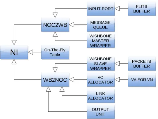
Figure 3.1 shows the NI architecture that is composed of two loosely coupled modules, the first module handles packets coming from the NoC, and sends them to the node over the bus. The second module receives messages from the bus and injects them into the network.
In particular, the Input Port receives flits coming from the NoC. When a tail flit arrives and an entire packet is received, the message is extracted and moved in the Message Queue. Thus, the message waits until it can be
transmitted over the bus through the WISHBONE Master Wrapper. On the other hand, a message is received from the bus thanks to the WISHBONE Slave Wrapper, while it remains packaged and stored in the Packet Buffer. After that, like for NoC, a virtual channel must be assigned at the packet and a link arbiter manage the transmission of various flits in the buffer on the single link available. The On-the-Fly table is only required if the bus doesn’t support split transaction, like the WISHBONE bus for now. The table tasks and the interaction between the Master and Slave Wrapper will be presented in Section 3.1.3.
All these discussed passages represent the stages of the two pipelines. Figure 3.2 shows the NoC-to-Node pipeline which has three stages working at different data granularity. The first works on flits, the second and the third on messages. In the first stage, Buffer Write (BW), the received flit coming from the upstream router is stored in the Input Port. The Packet-to-Message stage (PKT2MSG) is executed after all the flits of a packet have been stored, and extract the message from the packet and compute the needed bus transaction. In the last stage, Bus Arbitration (BA), the message is transmitted over the bus. Several BA stages take place if the message is bigger than the bus data width.
Figure 3.3 shows the Node-to-Noc pipeline which has four stages working on different granularity. The first and the second work on messages, the third and the fourth on flits. The first stage is the Message Write (MW) that stores a message, or part of it, received from a bus transaction. In the second stage, Message-to-Packet (MSG2PKT), when an entire message is received from the bus, the message is packaged and stored in the Packet Buffer. The second stage and the third stage, Virtual Channel Allocation (VA) and Link Allocation (LA), act like the NoC router VA and LA stages. The VA stage, passed only by the head flit, reserves an idle virtual channel in the output unit for the packet. The LA stage computes which flit can use the network link the next cycle, since the link is shared between all the stored packet in the Packet Buffer.
A detailed discussion is conducted on the principal modules of the ar-chitecture.
3.1.1 The Input Port Architecture
Given n the number of virtual networks, and m the number of virtual chan-nels per virtual network, the Input Port consists of n ∗ m buffers. Each of them can be used to store the entire flits of a packet. When an entire packet is stored, The Input Port requires at the Message Queue module if storage
Figure 3.1: The figure shows the proposed NI design for multi-node multi-core that interfaces a custom NoC and a WISHBONE bus.
Figure 3.2: NI pipeline stages crossed by packets coming from the NoC and destined to the bus
Figure 3.3: NI pipeline stages crossed by messages coming from the bus and destined to the NoC
is available and if the PKT2MSG stage can take place in the next cycle.
3.1.2 The Message Queue Architecture
The Message Queue is a memory buffer which stores messages waiting the bus arbitration. The implemented queue is composed of several buffers, each of them can store the longest message transmitted in the network. A free buffer is filled the cycle after the reception of a storage request from the Input Port. The module sends at the Master Wrapper the data to transmit and deletes a stored message when it has been transmitted to the node.
3.1.3 The WISHBONE Wrapper Architecture
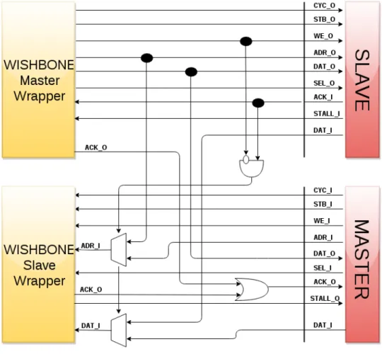
The implemented NI exposes the standard interface of a WISHBONE master and a WISHBONE slave IP, since it must act as a slave and a master from both the bus and the NoC perspective. Internally, to keep logically separated the reception and transmission of a message, the Slave Wrapper always receives messages, and the Master Wrapper always sends messages. This implies that the Slave Wrapper must receive the reply of a slave node to a read transaction started by the NI Master Wrapper, and the Master Wrapper must transmit the reply of a read transaction for the NI Slave Wrapper. Figure 3.4 shows in details the wrapper interactions. The rest of the section discusses every possible transaction to clarify the implementation.
When a packet is received, if it is a write transaction, it is simply sent by the Master Wrapper on the bus, since no reply must be sent back. If the packet contains a read transaction, the Master Wrapper start the transaction and the reply is stored in the Slave Wrapper. The Slave Wrapper does not allow the Master to start a read transaction if no space is available in the Packet Buffer.
When the NI acts as a slave two cases are possible. If it serves a write transaction, the Slave Wrapper receives the message and injects it in the NoC. If it serves a read transaction, the Slave injects the request in the NoC and saves an entry in the On-the-Fly table, with the information of the waited message. When the Master receives a packet that contains the reply for the transaction, it replies for the Slave and closes the transaction.
This kind of architecture is required to overcome the absence of split transaction in the WISHBONE bus. If this feature had been available it would not be need of the table, since in this case a master always sends and a slave always receives messages.
3.1.4 The Packet Buffer Architecture
The Packet Buffer represents a temporary storage for incoming packets from the bus that are waiting to be injected into the NoC. It is composed of several buffers, each of them can store the longest packet of the network. When a message is received by the WISHBONE Slave Wrapper, it is packeged and stored in a free buffer. If no free buffer are available, the WISHBONE Wrapper stops the communication and restart it only when space is freed. In this buffer the packet wait for virtual channel allocation and transmission of its flits. A buffer is freed the cycle after the tail flit of the packet won the link allocation.
3.1.5 The Virtual Channel Allocator Architecture
Traditionally, the Virtual Channel Allocator stage contains the critical path of the router pipeline. In the Network Interface this module is considerably less complex since a single output port is available.
An N : 1 arbiter is used for each virtual network. Each arbiter receives N requests, where N is the maximum number of packets that can be stored in the Packet Buffer, and allocates an available virtual channel only for one of them, if any. Note that this architecture does not underutilized the link bandwidth, since even if only one flit per cycle wins the VA stage, this flit will be transmitted on the only link available.
3.1.6 The Link Allocator Architecture
The Link Allocator is an arbiter N : 1, where N is the maximum number of packets that can be stored in the Packet Buffer. It receives the request transmission from the flits that have already won the VA stage. Only one of them can win and use the link to the router in the next cycle.
3.2
RTL Modules
The Network Interface model written in RTL Verilog has a modular imple-mentation that follows the architecture discussed in 3.1. Timing information about the pipelines stages have been obtained from this model. Furthermore, the pipeline changes allowed the extraction of conservative timing latency of three and two stages pipeline architectures as well as of a single cycle NI architecture.
Figure 3.5 shows the Verilog modules inclusions. In sub-module noc2wb all the NoC-to-Node pipeline is implemented and in sub-module wb2noc
all the Node-to-NoC pipeline is implemented. The decoupling of the two pipelines makes them easy to extend and optimize. The model can be adapted for other bus interfaces simply changing the wrapper modules. The On-the-Fly table can be removed from the implementation if the interfaced bus supports split transactions.
Figure 3.5: Verilog modules inclusion
3.3
An NI Software Implementation Integrated into
GEM5
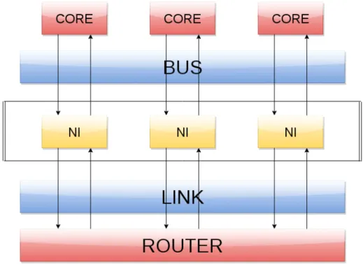
The performance overhead given by the inclusion of the proposed NI in a multi-node multi-core has been studied extending the GEM5 software [5]. Unfortunately, the simulator does not allow to model multi-node multi-core, since an NI has to be used between each cores or memory block and its local router in the Network-on-Chip.
To overcome this problem, all the network interfaces connected at the same router, which serve the cluster nodes, are treated like one NI. The NIs shares buffers, bus bandwidth and the router’s link. Figure 3.6 shows the approximation of the developed multi-node multi-core architecture. Only
one between the NI or a core in the node can transmit data to the bus at a time, and only one NI at a time can use the router link. The weakest assumption of this approximation is related to local messages. Local mes-sages are bus transactions between processing elements of the same cluster, so they do not need to be injected in the NoC. It has not been possible to prevent the passage of these messages in the Network-on-Chip, but their impact has been reduced. When inside an NI they do not occupy the shared resources.
GEM5 is written in C++. An object-oriented paradigm has been used to implement the NI software model. Each pipeline stage action has been implemented in a dedicated object, with the exception of the first stage of both pipelines. The first stages are executed from the Network Interface object, since it receives messages from the attached core and router. Each stages execution manipulate messages objects, stored in the Network In-terface, obtained from the previous stages or from the attached device, and provides messages to the next stage or to the connected device. The pipeline stages objects are instantiated at runtime by the Network Interface object, which is connected via message queue with a core or a memory controller, and via network link with a router.
Figure 3.6: The figure shows the speculation used to simulate a multi-node multi-core in the GEM5 software simulator. All the NIs attached at the same router are treated like one NI for the shared resources.
Chapter 4
Results
This chapter shows both timing and performance results of the proposed NI design considering different multi-core architecture. Several NI designs have been analyzed which differ on the structure of the pipeline. These different architectures have been discussed in Chapter 3.
Results highlights that the overhead of our architecture is composed of two subparts. The first part derives from the finite bandwidth of the additional bus and the pipeline stages that must be crossed by messages. The second part is due to the bus contention. Both these parts are not considered in the baseline model of GEM5. Is important underline that the first part of overhead is always fixed in a given architecture. This is not true for the bus contention.
Furthermore, timing results are presented of the RTL implementation of the pipeline stages. this allows an evaluation of the operating frequencies of the different NIs to find a validation of the pipeline design.
The rest of the Chapter is organized as follows. Section 4.1 describes the simulation environment setup, the simulated architectures and the used benchmarks. Section 4.2 presents the timing results. Sections 4.3 and 4.4 show the simulation results under synthetic and real traffic respectively.
4.1
Simulation Setup
The proposed NI designs have been implemented in an enhanced version [37, 35, 36] of the GEM5 cycle accurate simulator [5]. The simulator has been ex-tended to simulate a multi-node multi-core. For each simulated scenario the performance overhead have been extracted from the execution of different synthetic traffic patterns and real applications of the mibench benchmarks suite [14]. All the extracted results for the proposed NI models are compared
with the baseline NI model in GEM5 that is called baseline in the thesis. The baseline architecture consists in a NoC based multi-core, where each node in the same tile is connected with the NoC through a dedicated NI. As discussed in Chapter 3 the studied multi-node multi-core use a common NI shared between the nodes of the same cluster through a local bus. The NI interfaces the local bus with a NoC that connects the various tile. Table 4.1 presents the alias names, i.e. short names, for each implemented NI model that are used in the rest of this chapter. Note that the NI architecture are the same while the different number of stage implementation has been ob-tained starting from the 4 stage architecture then collapsing multiple stages in the same clock cycle. The default simulation parameters are detailed in Table 4.2.
Two configurations have been simulated for both synthetic traffic and real application simulation to highlight the different parts that compose the performance overhead of the multi-node multi-core with respect to the baseline architecture.
Name System
baseline NoC based multi-core with a vanilla NI model 1 stage Multi-node multi-core with one stage pipelines NI model 2 stage Multi-node multi-core with two stages pipelines NI model 3 stage Multi-node multi-core with three stages pipelines NI model 4 stage Multi-node multi-core with four stages pipelines NI model
Table 4.1: Alias table. The table shows short names used for the rest of the Chapter and the system which they refer.
4.1.1 Synthetic Traffic Setup
In the synthetic traffic setup 3 different traffic patters have been tested: uniform random, tornado and bit complement. Furthermore a 3 VNET NoC is considered to simulate coherence protocols like MESI and MOESI. One of the VNETs is considered the data VNET.
The traffic in the VNETs is unbalanced. First and second VNETs use a single flit packet size, while the third vnet use long data packet size to simulate the traffic of a real coherence protocol. Different data packet sizes and topologies have been tried to stress the bus interconnection of the multi-node multi-core. The first simulated architecture consists in a 8x8 2D-mesh topology with 64 cores, one for each tile. Synthetic traffic with data packet size of 1, 3, 5 and 9 flits has been used. This configuration has only one
Processor Core Out-of-Order Alpha Core
L1I Cache 32kB 2-way Set Associative
L1D Cache 32kB 2-way Set Associative
L2 Cache 256kB per bank, 8-way Set Associative
Coherence Prot. MOESI (3 VNET protocols)
Router 4-stage Wormhole Virtual Channelled
64bit Link Width Buffer Depth 4 Flits
2 Virtual Channels (VCs) for each Virtual Network 3 Virtual Networks
Network Interface 64bit Bus Width
Buffer Depth Message Queue: 6 messages Buffer Depth Packet Buffer: 4 packets
Topology 2D-mesh 2x2 / 4x4 / 8x8
Table 4.2: Experimental setup: core and router architectures for the GEM5 simulation.
traffic generator in a tile. Thus the bus contention part of the performance overhead is negligible with respect to the bus transmission and pipeline stages overhead.
The second architecture consists in a 2x2 2D-mesh topology with 16 cores, four for each tile. The data packet size used is 64 bytes. In this configuration is the bus contention that plays a significant role in the per-formance overhead, highlighting the limits of the bus interconnection system when highly stressed. Furthermore, it shows the inadequacy of the simu-lation results trying to approximate the considered multi-node multi-core with the baseline GEM5 model.
4.1.2 Real Benchmark Setup
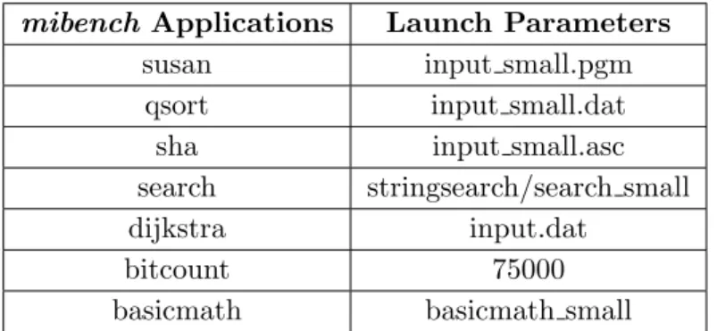
A reduced set of applications of the mibench suite has been used. Table 4.3 exhibits the seven applications of the suite that has been chosen with the launch parameters details. The applications have different traffic character-istics used to evaluate the performance of the proposed NI designs under real traffic. They are single threaded applications, thus a number of instances equal to the number of cores in the architecture is used.
Two systems have been analyzed. The first simulated system considers a 4x4 2D-mesh NoC topology with 1, 2 and 4 cores per tile. This implies a total number of cores equal to 16, 32 and 64. The cache configuration, coherence protocol and NI parameters are listed in Table 4.2. The second
simulated system varies from the first in the NoC topology, a 2x2 2D-mesh, and has 8 cores per tile.
mibench Applications Launch Parameters
susan input small.pgm
qsort input small.dat
sha input small.asc
search stringsearch/search small
dijkstra input.dat
bitcount 75000
basicmath basicmath small
Table 4.3: mibench applications used with the detailed input parameters of each appli-cation.
4.2
Timing Results
Starting from the NI RTL implementation, this section discusses the clock period while a different number of pipeline stages is considered for the NI. The clock periods of the basic pipeline stages are reported in Table 4.4 considering the proposed 4 stages pipeline. The pipeline stages are almost balanced for a first NI implementation, while different optimizations are still possible. In particular, the effort has been devoted in the efficient pipeline design starting from a methodological evaluation of the division between each stage. However, the Message to Packet stage is unbalanced with respect to the others. This is due to the need to split the transformation of the message coming from the bus into a packet while the packet is completely received from the bus. Otherwise, the single aggregate pipeline stage should pack both the packet to message and the buffer write that depends on the bus implementation timing.
A conservative evaluation of the clock period of the NI designs are re-ported in Table 4.5 with the percentage increment with respect to the four stages architecture. The periods of pipeline architectures with less then 4 stages have been obtained collapsing multiple stages in the same clock cy-cle. With the exception of the 4 stages pipeline, all the other architectures have the critical path in the Node-to-NoC pipeline due to the inability to parallelize the VA and LA stages. The 4 stages pipeline has its critical path in the Bus Arbitration stage of the NoC-to-Node pipeline.
(a) NoC-to-Node pipeline
Stage Clock Period
Buffer Write 3.068ns
Packet to Message 2.77ns Bus Arbitration 4.711ns
(b) Node-to-NoC pipeline
Stage Clock Period
Message Write 4.207ns
Message to Packet 1.871ns
Virtual Channel Allocation 3.354ns
Link Allocation 2.892ns
Table 4.4: Table 4.3(a) presents the clock periods of the basic stages of the NoC-to-Node pipeline, while Table 4.3(b) shows the clock periods of the NoC-to-Node-to-NoC stages. A detailed discussion of these stages is in Section 3.1.
between the 4 stages and the 3 stages design. This highly encourages the usage of the 4 stages NI architecture.
Pipelines Width Clock Period Percentage Overhead
1 Stage 7.843ns 66%
2 Stages 7.264ns 54%
3 Stages 6.163ns 30%
4 Stages 4.711ns 0%
Table 4.5: The table presents a conservative evaluation of the clock period for the 4 presented NI designs. The last column shows the percentage overhead with respect to the 4 stages pipeline architecture NI design.
4.3
Synthetic Traffic Results
This section presents the synthetic traffic results exploiting two multi-node multi-core topologies. The two architectures are analyzed to emphasize dif-ferent aspects. The first simulated architecture consist in a 8x8 2D-mesh. In each tile there is one core, and a directory controller that only receives messages. This configuration is used to analize the overhead introduced by the different pipeline architecture and the latency required to transmit data over the bus.
packets are used. The 1 stage NI architecture provides almost the same latency of the baseline for low traffic. This is due to the single pipeline stage and the single flit message that are not impacting both the contention metric of the node bus. Moreover, the 2 stages introduces 2 more latency cycles with respect to the 1 stage, due to an additional pipeline stage in each traversed NI. Similarly, the 3 stages adds 4 more latency cycles, and the 4 stages architecture adds 6 cycles, with respect to the 1 stage, due to their additional pipeline stages in each traversed NI.
Figure 4.2 presents the results with single flit packets for two VNET, and three flits packet for the third. In this scenario also the 1 stage architecture starts with an higher latency then the baseline also for low injection rate. This is given by the finite bus bandwidth against the unlimited modelled bandwidth of the link between the NI and the core in the baseline.
For higher injection rate there is an increasing contention on the bus that leads to a deviation from the baseline latency of all the architectures.
Figure 4.3 better investigates these aspects. Results for Uniform Random synthetic traffic type are shown, using a different packet size for the third VNET for each figure. Long packets increase the number of cycles required to transmit a packet to the bus and also increase the probability to have a busy bus when another core on the same tile is willing to transmit or receive a packet. Note that the deviation from the baseline is greatly influenzed by the bus contention, not by the number of pipeline stages.
Figure 4.4 shows the performance overhead in a system with high con-tention on the bus. It consists in a 2x2 2D-mesh with in each tile 4 cores and a directory controller. Similar to NUMA architectures currently avail-able. In this scenario the bus contention latency prevails in the performance overhead. The saturation point comes for considerably less injection rate with respect to the baseline, highlighting again the inaccuracy of the vanilla NI model in GEM5. Moreover, this architecture shows that the saturation doesn’t depend on the number of pipeline stages, but it depends from the high traffic on the bus.
4.4
Real Traffic Results
This section provides the results using the mibench applications.
First of all, Figure 4.5 allows a categorization of the applications based on the injected traffic. It this context we can call hello and qsort high traf-fic applications. sha and bitcount low traftraf-fic applications. The remaining benchmarks will be identified as medium traffic applications. These catego-rization allows a better explanation of the results in the rest of the section.
(a) Uniform Random
(b) Tornado
(c) Bit Complement
Figure 4.1: Average packet latency with data packet size of one flit. Different synthetic traffic pattern are used: uniform random, tornado and bit complement.
(a) Uniform Random
(b) Tornado
(c) Bit Complement
Figure 4.2: Average packet Latency with data packet size of three flits. Different synthetic traffic pattern are used: uniform random, tornado and bit complement.
(a) Data packet size 3
(b) Data packet size 5
(c) Data packet size 9
Figure 4.3: Average packet latency with uniform random traffic type and packet sizes of three, five and nine flits.
(a) Uniform Random
(b) Tornado
Figure 4.4: Average packet Latency with data packet size of nine flits in a 2x2 2D-mesh with four cores per tile. Two synthetic traffic patterns are used: uniform random and tornado. The figures highlights the inadequacy of the vanilla NI model of GEM5 in a configuration with high injected traffic.
(a) One Core per Tile
(b) Two Cores per Tile
(c) Four Cores per Tile
Figure 4.5: The figures depict the average injection rate of real applications in a 4x4 2D-mesh with several number of attached core.
Two different configurations have been simulated to analyze different aspects.
4.4.1 A Low Contention System Case
The first analyzed system consists in a 4x4 2D-mesh and has been simulated with 1, 2 and 4 attached cores per tile. Other configuration parameters can be found in Table 4.2. This system has been used to test the multi-node multi-core in a low contention environment.
Figure 4.6 shows the performance overhead on the total execution time. Different consideration can be made on the basis of the categorization intro-duced at the beginning of this section. Low traffic applications, like sha, do not introduce a significant overhead with respect to the baseline architecture due to the low contention on the on-tile bus. Medium traffic benchmark in-troduce an overhead less then the 5%. High traffic applications, like qsort, have the greatest impact but it is limited of about the 10%. Note that increasing the number of pipeline stages in the NI does not lead to a con-siderable increase of the overhead. For example as depicted in Figure 4.6(a) for the qsort application, using a 4 stages pipeline NI architectures only increase the performance overhead of about the 5% with respect to the 1 stage pipeline architecture.
Figure 4.6 highlights that the traffic overhead of the architectures with more core per tile leads to worst performance only for high traffic applica-tions. However, since all these applications have a low traffic injection, the performance degradation is negligible.
4.4.2 An High Contention System Case
This section examines a configuration with high contention on the local bus. The system consists in a 2x2 2D-mesh with 8 core per tile. Other configuration parameters can be found in Table 4.2.
Figure 4.8 shows the results considering a 2x2 2D-mesh where each tile implements 8 cores. This results clearly highlights how the contention on the bus leads to totally different performance between the proposed NI model and the one proposed in the baseline GEM5 implementation, thus supporting the claim for a better NI GEM5 model to evaluate multi-node multi-core architectures.
(a) One Core per Tile
(b) Two Cores per Tile
(c) Four Cores per Tile
Figure 4.6: mibench execution time overhead per core. In each subfigures is fixed the number of cores and vary the simulated architectures
(a) One stage pipeline
(b) Two stages pipeline
(c) Three stages pipeline
(d) Four stages pipeline
Figure 4.7: mibench execution time overhead per NI model. In each subfigures the simulated system is fixed and the number of attached cores varies.
Figure 4.8: mibench execution time in a 2x2 2D-mesh with 8 core per tile. This system shows the performance degradetion in a system with high bus contention.
Chapter 5
Conclusions and Future
Works
Considering the current trend towards multi-node multi-core architectures, where each node is composed of a multi-core and multiple nodes and glued into a single system towards a dedicated intra-node interconnect, the thesis explores different trades-off issues and solutions for the implementation of the Network Interface (NI) controller for such systems. The NI represents the junction point between the inter-node and intra-node interconnect, thus playing a crucial rule in the performance of the whole system. Moreover, the resource allocation and the NI design represent a critical decision point for the power-performance-area optimizations.
A novel pipelined NI model has been developed in RTL Verilog and a soft-ware model has been integrated in the GEM5 multi-core softsoft-ware simulator. The proposed NI has been evaluated from the timing and the performance viewpoint. First, different pipeline stages are considered for the same NI ar-chitecture providing an in depth timing analysis where the 4-stage pipeline emerges as the best candidate from the proposed results. Second, the perfor-mance evaluation considering different architectures and both synthetic and real applications traffic patterns demonstrated the need for a more accurate NI model to address multi-node multi-cores.
In particular, the proposed results highlights two different contributions that make the accurate NI model and the GEM5 one to drift in the simulated architecture. First, the additional latency due to the additional inter-node bus architecture and the NI pipeline stages. Second, the bus contention when multiple cores are implemented in the same node. It is worth noticing that the second contribution greatly overcomes the first one, highlighting the bus contention as the first issues that requires the use of a mire accurate
NI model in the GEM5 simulator.
5.1
Future Works
The proposed Network Interface design requires more in-depth analysis. First of all, a complete support for multi-node multi-cores simulation must be developed. This is a great lack and does not allow the extraction of precise information from these systems. Furthermore, it doesn’t allow a fast design space exploration and comparison between multi-cores based on heterogeneous interconnection and multi-cores based on homogeneous one.
A design exploration of the architecture is required to dimension the shared resources of the Network Interface, like the number of message buffers or the bus data width. Most of these design decisions influence the area and latency trade-off.
The pipeline can be extended to support several end to end features. For example insert a compression/decompression stage can be a good addition. The insertion of a new pipeline stage in both the pipelines will increase the NI latency overhead, but the injected packets will be smaller and the NoC less stressed. It can results in a lower total transmission latency.
Low power optimization can be studied to reduce power consumption or to improve the reliability of some part of the architecture [32, 33, 34] or both [30]. The presence of many buffers, and their sizing to support high traffic, makes the Network Interface a good candidate for this kind of optimization. Power consumption of buffers, especially leakage power, is a considerable part of the total power consumption and it must be reduced. Another interesting research branch regards applications dispatch. It can be studied the impact of dispatch the applications that requires inter-process communication in the same clustered node and reserve for them the local shared cache. Almost all the cores communication will be transmitted over the local bus, and not injected in the network. Thus the Network Interface traffic will be reduced and less shared resources used.
Bibliography
[1] Federico Angiolini, Paolo Meloni, Salvatore Carta, Luca Benini, and Luigi Raffo. Contrasting a noc and a traditional interconnect fabric with layout awareness. In Proceedings of the Conference on Design, Au-tomation and Test in Europe: Proceedings, DATE ’06, pages 124–129, 3001 Leuven, Belgium, Belgium, 2006. European Design and Automa-tion AssociaAutoma-tion.
[2] J. Balfour and W.J. Dally. Design tradeoffs for tiled cmp on-chip net-works. In Proceedings of the 20th annual international conference on Supercomputing, pages 187–198. ACM, 2006.
[3] L. Benini and G. De Micheli. Networks on chips: a new soc paradigm. Computer, 35(1):70–78, Jan 2002.
[4] P. Bhojwani and R. Mahapatra. Interfacing cores with on-chip packet-switched networks. In VLSI Design, 2003. Proceedings. 16th Interna-tional Conference on, pages 382–387, Jan 2003.
[5] Nathan Binkert, Bradford Beckmann, Gabriel Black, Steven K. Rein-hardt, Ali Saidi, Arkaprava Basu, Joel Hestness, Derek R. Hower, Tushar Krishna, Somayeh Sardashti, Rathijit Sen, Korey Sewell, Muhammad Shoaib, Nilay Vaish, Mark D. Hill, and David A. Wood. The gem5 simulator. SIGARCH Comput. Archit. News, 39(2):1–7, Au-gust 2011.
[6] Evgeny Bolotin, Israel Cidon, Ran Ginosar, and Avinoam Kolodny. Qnoc: Qos architecture and design process for network on chip. Jour-nal of Systems Architecture, 50(23):105 – 128, 2004. Special issue on networks on chip.
[7] W. Chouchene, B. Attia, A. Zitouni, N. Abid, and R. Tourki. A low power network interface for network on chip. In Systems, Signals and Devices (SSD), 2011 8th International Multi-Conference on, pages 1–6, March 2011.
[8] W.J. Dally. Virtual-channel flow control. Parallel and Distributed Sys-tems, IEEE Transactions on, 3(2):194–205, Mar 1992.
[9] W.J. Dally and B.P. Towles. Principles and practices of interconnection networks. Elsevier, 2004.
[10] J. Duato. A new theory of deadlock-free adaptive routing in wormhole networks. Parallel and Distributed Systems, IEEE Transactions on, 4(12):1320–1331, Dec 1993.
[11] J. Duato and T.M. Pinkston. A general theory for deadlock-free adap-tive routing using a mixed set of resources. Parallel and Distributed Systems, IEEE Transactions on, 12(12):1219–1235, Dec 2001.
[12] Alberto Ferrante, S. Medardoni, and D. Bertozzi. Network interface sharing techniques for area optimized noc architectures. In Digital Sys-tem Design Architectures, Methods and Tools, 2008. DSD ’08. 11th EUROMICRO Conference on, pages 10–17, Sept 2008.
[13] J. Flich and D. Bertozzi. Designing Network On-Chip Architectures in the Nanoscale Era. Chapman & Hall/CRC Computational Science. CRC Press, 2010.
[14] M.R. Guthaus, J.S. Ringenberg, D. Ernst, T.M. Austin, T. Mudge, and R.B. Brown. Mibench: A free, commercially representative embedded benchmark suite. In Workload Characterization, 2001. WWC-4. 2001 IEEE International Workshop on, pages 3–14, Dec 2001.
[15] S.M. Hassan and S. Yalamanchili. Centralized buffer router: A low latency, low power router for high radix nocs. In Networks on Chip (NoCS), 2013 Seventh IEEE/ACM International Symposium on, pages 1–8, April 2013.
[16] P. Kermani and L. Kleinrock. Virtual cut-through: A new com-puter communication switching technique. Comcom-puter Networks (1976), 3(4):267–286, 1979.
[17] A. Leroy, J. Picalausa, and D. Milojevic. Quantitative comparison of switching strategies for networks on chip. In Programmable Logic, 2007. SPL ’07. 2007 3rd Southern Conference on, pages 57–62, Feb 2007. [18] Sheng Li, Jung Ho Ahn, R.D. Strong, J.B. Brockman, D.M. Tullsen,
and N.P. Jouppi. Mcpat: An integrated power, area, and timing mod-eling framework for multicore and manycore architectures. In
Microar-chitecture, 2009. MICRO-42. 42nd Annual IEEE/ACM International Symposium on, pages 469–480, Dec 2009.
[19] L.M. Ni and P.K. McKinley. A survey of wormhole routing techniques in direct networks. Computer, 26(2):62–76, Feb 1993.
[20] J. Power, J. Hestness, M.S. Orr, M.D. Hill, and D.A. Wood. gem5-gpu: A heterogeneous cpu-gpu simulator. Computer Architecture Letters, 14(1):34–36, Jan 2015.
[21] A. Radulescu, J. Dielissen, S.G. Pestana, O.P. Gangwal, E. Rijpkema, P. Wielage, and K. Goossens. An efficient on-chip ni offering guaran-teed services, shared-memory abstraction, and flexible network config-uration. Computer-Aided Design of Integrated Circuits and Systems, IEEE Transactions on, 24(1):4–17, Jan 2005.
[22] Ahmed H. M. Soliman, E. M. Saad, M. El-Bably, and Hesham M. A. M. Keshk. Designing a WISHBONE protocol network adapter for an asynchronous network-on-chip. CoRR, abs/1203.4150, 2012.
[23] F. Steenhof, H. Duque, B. Nilsson, K. Goossens, and R.P. Llopis. Net-works on chips for high-end consumer-electronics tv system architec-tures. In Design, Automation and Test in Europe, 2006. DATE ’06. Proceedings, volume 2, pages 1–6, March 2006.
[24] K. Swaminathan, G. Lakshminarayanan, F. Lang, M. Fahmi, and Seok-Bum Ko. Design of a low power network interface for network on chip. In Electrical and Computer Engineering (CCECE), 2013 26th Annual IEEE Canadian Conference on, pages 1–4, May 2013.
[25] A.N. Udipi, N. Muralimanohar, and R. Balasubramonian. Towards scalable, energy-efficient, bus-based on-chip networks. In High Perfor-mance Computer Architecture (HPCA), 2010 IEEE 16th International Symposium on, pages 1–12, Jan 2010.
[26] P. Wielage and K. Goossens. Networks on silicon: blessing or night-mare? In Digital System Design, 2002. Proceedings. Euromicro Sym-posium on, pages 196–200, 2002.
[27] Kisoo Yu, Donghee Han, Changhwan Youn, Seungkon Hwang, and Jaechul Lee. Power-aware task scheduling for big.little mobile pro-cessor. In SoC Design Conference (ISOCC), 2013 International, pages 208–212, Nov 2013.
[28] Jia Zhan, M. Poremba, Yi Xu, and Yuan Xie. Leveraging delta com-pression for end-to-end memory access in noc based multicores. In De-sign Automation Conference (ASP-DAC), 2014 19th Asia and South Pacific, pages 586–591, Jan 2014.
[29] Ping Zhou, Bo Zhao, Yu Du, Yi Xu, Youtao Zhang, Jun Yang, and Li Zhao. Frequent value compression in packet-based noc architectures. In Proceedings of the 2009 Asia and South Pacific Design Automation Conference, ASP-DAC ’09, pages 13–18, Piscataway, NJ, USA, 2009. IEEE Press.
[30] D. Zoni, L. Borghese, G. Massari, S. Libutti, and W. Fornaciari. Test: Assessing noc policies facing aging and leakage power. In EUROMICRO DSD/SEAA, Funchal, Madeira, PORTUGAL, Aug 26-28, pages 1–8, 2015.
[31] D. Zoni, J. Flich, and W. Fornaciari. Cutbuf: Buffer management and router design for traffic mixing in vnet-based nocs. Parallel and Distributed Systems, IEEE Transactions on, PP(99):1–1, 2015.
[32] D. Zoni and W. Fornaciari. A sensor-less nbti mitigation methodol-ogy for noc architectures. In SOC Conference (SOCC), 2012 IEEE International, pages 340–345, 2012.
[33] D. Zoni and W. Fornaciari. Nbti-aware design of noc buffers. In Pro-ceedings of the 2013 Interconnection Network Architecture: On-Chip, Multi-Chip, IMA-OCMC ’13, pages 25–28, New York, NY, USA, 2013. ACM.
[34] D. Zoni and W. Fornaciari. Sensor-wise methodology to face nbti stress of noc buffers. In Design, Automation Test in Europe Conference Ex-hibition (DATE), 2013, pages 1038–1043, March 2013.
[35] D. Zoni and W. Fornaciari. Modeling dvfs and power gating actuators for cycle accurate noc-based simulators. Journal of Emerging Technolo-gies in Computing Systems, pages 1–15, 2015.
[36] D. Zoni, F. Terraneo, and W. Fornaciari. A control-based methodology for power-performance optimization in nocs exploiting dvfs. Journal of Systems Architecture, 61(56):197 – 209, 2015.
[37] D. Zoni, F. Terraneo, and W. Fornaciari. A dvfs cycle accurate simu-lation framework with asynchronous noc design for power-performance optimizations. Journal of Signal Processing Systems, pages 1–15, 2015.