Challenges in plasma and laser wakefield accelerated beams diagnostic
A. Cianchia,∗, M. P. Ananiab, M. Bellavegliab, M. Castellanob, E. Chiadronib, M. Ferrariob, G. Gattib, B. Marchettic, A. Mostaccif, R. Pompilib, C. Ronsivalled, A.R. Rossie, L. Serafinie
aUniversity of Rome Tor Vergata and INFN, V. della Ricerca Scientifica 1, 00133 Rome, Italy bINFN-LNF - Via E. Fermi 40, 00044 Frascati (RM), Italy
cDESY, Platanenallee 6, D-15738 Zeuthen, Germany dENEA C.R. Frascati, Via E. Fermi,45 00044 Frascati (RM), Italy
eINFN-Mi, Via Celoria, 16 20133 Milano, Italy
fUniversity of Rome La Sapienza, P.le Aldo Moro 5, 00185 Rome (Italy)
Abstract
The new frontier in the particle beam accelerator is the so called plasma acceleration. Using the strong electric field inside a plasma is possible to achieve accelerating gradients order of magnitude larger with respect to the actual technologies. Different schemes have been proposed and several already tested, producing beams of energy of several GeV. Mainly two approaches are followed: either the beam is directly produced by the interaction of a TW/PW class laser with a gas jet, or a preexisting particle beam is accelerated in a plasma channel. In both cases a precise determination of the emerging beam parameters is mandatory for the fine tuning of the devices. The measurement of these parameters, in particular the emittance, is not trivial, mainly due to the large energy spread and to the tight focusing of these beams or to the background noise produced in the plasma channel. We show the problems related to the diagnostic of this kind of beams and the proposed or already realized solutions.
Keywords:
beam diagnostic, plasma wakefield acceleration, emittance
1. Introduction
Conventional accelerating Radio-Frequency (RF) structures are limited in the achievable gradient. Depending by the used frequency it ranges between tens to one hundred MeV/m. The past few years have seen a great progress in the field of accelerating particle by means of plasma acceleration ([1],[2],[3],[4],[5],[6],[7]). This wide category includes several different methods. We focus mainly our attention to Laser Wakefield Accelerator (LWFA) and Beam Driven Plasma Wakefield Accelerator (PWFA).
In LWFA, the ponderomotive force of a laser pulse traveling through underdense plasma can
∗Corresponding author
Email address:
[email protected] (A. Cianchi)
excite a plasma wave with longitudinal electric fields larger than 10 GV/m. These fields may be utilized to accelerate electrons to ultrarelativistic energies on a centimeter scale.
TW-class laser are needed in order to provide the required electric field, tightly focused in a spot of few µm. Therefore high divergent beams (about 1 mrad or more) are produced, with also a big energy spread, larger than 1%. While sev-eral experiments are available for such a scheme, no one has so far used the PWFA. In 2007 [8] an energy gain of more than 42 GeV was achieved in a plasma wakefield accelerator of 85 cm length, driven by a 42 GeV electron beam at the Stanford Linear Accelerator Center (SLAC). This proof of principle experiment is not exactly the PWFA. In the case of the SLAC experiment a bunch much
longer than the plasma wavelength has been in-jected into the plasma, so some parts of the beam were accelerated, while other parts decelerated. The aim of the PWFA is the injection of a train of separated pulses. A plasma wave/wake is excited by relativistic particle bunches. Some of them loose energy to the plasma (driving beams), and one is accelerated (witness bunch). Typical val-ues for plasma density are in the order of about 1016 cm−3, 100 µm for plasma wavelength and gradient in the order of 10 GV/m. Bunch trains, with features that can be successfully used for this application are now available and experiment are foreseen in the next future [9].
2. Diagnostic challenges
So far electron beams have been produced and accelerated through plasma wakefield acceleration as proof-of-principle experiments. Now the aim is producing high quality beams. It means a severe control of the beam parameters in order to use it for several applications. The diagnostic plays a crucial role in the determination of the beam parameters. Unfortunately the conventional elec-tron beam diagnostic faces several problems when applied to these beams. These problems will be clearly addressed in the following chapters. More-over the main issue is the lack of simulations. The interaction of the electrons within the plasma is indeed very difficult and time consuming to simu-late. Only few simulated samples of such a beams are then available. This point is crucial in or-der to design and realize a satisfactory diagnos-tic system. In this paper we focus only on the measurements of the beam emittance, that it is defined in the next chapter. This is the most rel-evant parameter and sometimes the most difficult to estimate. The beam current, the total charge as well as the longitudinal properties can be re-trieved applying conventional diagnostic methods [10] to such beams.
3. Emittance
The main parameter of an electron beam is the emittance. For sake of simplicity we can define it
as the volume occupied by the beam in the phase space. Under the conditions of the Liouville the-orem the emittance is a motion invariant.
3.1. Normalized Emittance
The most common parameter in a particle ac-celerator is the normalized emittance. The defi-nition of the r.m.s. (root mean square) emittance is the following:
ε2n =⟨x2⟩ ⟨β2γ2x′2⟩− ⟨xβγx′⟩
where γ is the usual relativistic factor, β is the ratio between the speed of the particle and the light and x, x’ are the position and the tranverse velocity of every particles. The average is over all the particles in the bunch. Such a definition is misleading for a typical plasma accelerated beam where both the energy spread and the angular di-vergence are at least an order of magnitude larger than conventional beam, as pointed out in [11]. If the correlation between the energy and trans-verse position is negligible, as in a drift without collective effects, we can write
ε2n =⟨x2⟩ ⟨β2γ2⟩ ⟨x′2⟩− ⟨βγ⟩2⟨xx′⟩2
Using the definition of energy spread
σE2 = ⟨β
2γ2⟩ − ⟨βγ⟩2
⟨γ⟩2
and replacing it in the former equation we have
ε2 n=⟨γ⟩ 2 σ2 E⟨x2⟩ ⟨x′2⟩ + ⟨βγ⟩2(⟨x2⟩ ⟨x′2⟩ − ⟨xx′⟩2)
The second term is called geometrical emittance. The first term is usually totally negligible when we consider conventional accelerated beam. In our case the large value of the energy spread as well as the big angular divergence (in the order of the mrad) makes the first term the leading one. This contribution is not constant and increases with the distance from the plasma, being the beam size mainly dominated by the angular divergence. In this scenario the normalized emittance is not con-stant and depends on the position of the measure-ment. However we focus here on the geometrical emittance, which is the measured quantity. In the [11] the relation between normalized and geomet-rical emittance are clearly addressed.
3.2. Pepper pot
When particle beams are strongly dominated by the space charge, usually in the energy range of few MeV, the most used technique to retrieve the emittance value is the so called pepperpot tech-nique. Details concerning this measurement can be found in [12], while in [13] the method for data elaboration and processing is discussed.
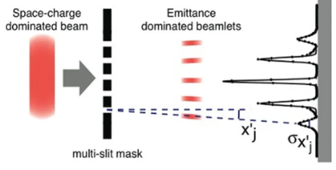
An intercepting multi-slit or hole mask se-lects an array of beamlets. The space charge dominated incoming beam is thus reduced into emittance-dominated beamlets that drift up to an intercepting screen(see Fig. 1). If the screen re-sponse is linear, the intensity of beamlets spots on the screen is directly proportional to the num-ber of particles in the beamlets which hit the screen. The emittance can be retrieved calcu-lating the second momentum of the beam. The slits mask must stop, or largely degrade, the in-tercepted components of the beam, while avoiding excessive slit scattering effects.
Figure 1: Pepper pot layout
Some people have already applied this tech-nique to plasma accelerated beams, see for exam-ple [15]. However, an unwanted cut of the trans-verse phase space due to the used device is clearly visible in this paper. As a consequence the verti-cal size of the camera does not contains the whole beam. This problem leads to an underestimation of the emittance. Furthemore a critical undersam-pling of the transverse phase space is also present. To clarify this problem we can compare the phase space of three different situations (see Fig.2).
All of them refers to beams at 60 cm from the source. In A there is the phase space of a typi-cal electron beam, 5 MeV, initial spot size 1 mm. The pepperpot technique has been invented for
Figure 2: A: phase space of a typical electron beam, 5 MeV, initial spot size 1 mm, drift from the source 60 cm; B: phase space of a possible plasma accelerated beam, 500 MeV initial spot size 10 µm, drift from the source 60 cm; C: phase space of a possible beam plasma accelerated, 500 MeV, initial spot size 1µm, drift from the source 60 cm.
this kind of beams. In B it is shown a phase space of a possible plasma accelerated beam, 500 MeV with initial spot size 10 µm. In C there is again a phase space of a possible plasma accel-erated beam, identical to B but with initial spot size 1 µm. The pepperpot method samples the beam phase space. It is clear, especially from plot C, that when we consider beams with high angu-lar divergence with respect to the beam size, the phase space collapses in a tiny line.
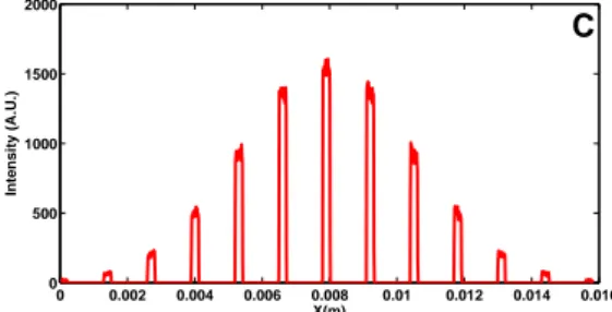
In Fig.3 we compared the intensity distribu-tions of the signal on the detecting screen down-stream the mask. The number of the slits, their distance and their sizes are optimized in order to minimize the error due to the the sampling na-ture of this technique, considering only that val-ues that can be used in a real tungsten slit ma-chining [14]. We completely neglect any effect coming from the multiple scattering in the ma-terial as well as any consideration about the Sig-nal to Noise Ratio (SNR). We focus only on the sampling properties of this method. In the plot A we show the distribution which results applying a mask on the beam with phase space A in Fig.2. The mask is placed at 60 cm and the screen at 2 m from the mask. The holes size is 50 µm, while the distance between them is 500 µm. In this con-dition the percentage error coming only from the sampling properties of this method is about 1%.
0 0.5 1 1.5 2 2.5 3 x 10⁻³ 0 500 1000 1500 2000 X (m) Intensity (A.U.) A 0 0.2 0.4 0.6 0.8 1 1.2 1.4 1.6 1.8 2 x 10⁻³ 0 2000 4000 6000 8000 10000 12000 14000 X (m) Intensity (A.U.) B
Figure 3: Left: beam initial spot size=1 mm, 5 holes, 50 µm diameter, 500 µm distance between holes, 60 cm from the source, 2 m distance between mask and screen, estimated error=1% Right: beam initial spot size=10 µm, 9 holes, 25 µm diameter, 50 µm distance between holes, 60 cm from the source, 2 m distance between mask and screen, estimated error=37%
of B type phase space. The mask is placed at 60 cm and the screen at 2 m from the mask. The holes size is 25 µm, while the distance between them is 50 µm. In this condition the percentage error coming only from the sampling properties of this method is about 37%. This last beam can be representative of some type of plasma accelerated beam. An initial spot size of 10 µm give an error that, even if quite larger with respect to typical emittance monitors for beam diagnostic, is still tolerable. This is not the case reported in Fig.4.
0 0.002 0.004 0.006 0.008 0.01 0.012 0.014 0.016 0 500 1000 1500 2000 X(m) Intensity (A.U.) C
Figure 4: Beam initial spot size=1 µm, 13 holes, 50µm diameter, 300µm distance between holes, 60 cm from the source, 2 m distance between mask and screen, estimated error=1800%
Here with an initial beam spot of 1 µm rms, the phase space (type C Fig.2) is so thin that the sampling is completely inefficient. It is manly due to the large aspect ratio between beam size at the source and its divergence, in the order of 1:1000, while usually this value is close to 1:1!
Reference [16] reports on an interesting mea-surement of the beam emittance using this tech-nique. Except for the definition of the normal-ized emittance, that we have already shown is
improper in this case, a simple estimation of the undersampling error in their case leads to a rea-sonable 47% in the case of an initial spot size of 10 µm and a value 20 times larger if we suppose it was about 1 µm. Therefore we can conclude from our analysis that, if we consider the error due to undersampling the thin phase space the main limiting factor of this measurement, a ini-tial beam spot size less than 10 µm rms produces a phase space that cannot be resolved with this technique. The problems related to the multiple scattering as well as the SNR ratio in case of high energy beams does not seems a limiting factor as clearly addressed in [17].
3.3. Quadrupole scan
The main advantage of the pepperpot technique is the single shot capability. The intrinsic insta-bility inside the plasma channel produces differ-ent beams from shot to shot. If we can con-sider to accumulate a long statistics in order to damp these fluctuations also multi shot measure-ments are feasible. In this scenario the most pop-ular technique for emittance measurement is the quadrupole scan [10]. It is possible to measure the beam emittance changing the strength of a magnetic lens and recording the beam spot size downstream. With at least 3 different measure-ments is possible to retrieve the elemeasure-ments of the sigma matrix that are related with the emittance. The main concern is the large energy spread of the beam that produces an unwanted emittance dilu-tion due to chromatic effect in the quadrupoles. We evaluated [18] which is the contribution of the chromaticity in an emittance measurement with a single quadrupole. A moderate spot size, about 300 µm, with an energy of the order of 150 MeV, an energy spread of about 1% and a normalized emittance of 1.5 mm-mrad, gives an emittance di-lution only of 1%. But if the spot size is increased up to 1.7 mm for instance, the increment in the emittance is already in the order of 50%.
Due to the large angular divergence of the beam the spot size is almost completely dominated by the divergence. So the distance between the beam waist and the quadrupole used for the diagnostic must be set so that the beam size is so small at
that energy that the chromatic effects do not af-fect the measurement. For instance in the case considered above half a meter is a reasonable dis-tance. This value must be compatible with the experimental setup. Usually the plasma interac-tion happens in a dedicated vacuum chamber and sometimes mechanical constrains avoid to place any device at a distance shorter than 10-20 cm. Therefore we consider the quadrupole scan tech-nique, even if with the problems that we high-lighted concerning the multi-shot nature of such a diagnostic and the limits that can arise for me-chanical constrains, a promising candidate for re-liable emittance measurement.
3.4. Multi monitors
Another popular method for emittance mea-surement is the so called multiple monitors. In this case the beam size is measured in three dif-ferent positions and the values of the beam spots are used in order to retrieve the emittance. This is a multi shot measurement. A very intriguing experiment is presented in [19]. The authors used very thin aluminum foils (about 3 µm thickness) to produce optical transition radiation when the beam pass through the foils. The radiation com-ing from every screen is collected by 3 different CCD camera at the same time. Therefore this de-vice can be used to produce single shot measure-ment. The contribution of multiple scattering to the intrinsic angular spread of the beam is demon-strated to be negligible in their experimental con-ditions. They tested the system on a conventional accelerated electron beam at 3 GeV. The multi-ple scattering angle is inversely proportional to the particle energy. When we consider to apply this method to beams of energy ten times smaller, the contribution of multiple scattering is not neg-ligible anymore. For this reason we consider the method very interesting but only for beam ener-gies greater than 1 GeV.
4. Conclusions
In this paper we focused on the difficulties re-lated to the measurement of the emittance of par-ticle beams accelerated by means of plasma inter-action. The main problem of these beams are
the big energy spread, larger than 1%, and the huge angular divergence, more than 1 mrad. We pointed out that in this condition the usual defi-nition of normalized emittance must be reconsid-ered. We also compared several method in order to measure the emittance. We conclude that sin-gle shot methods are preferable, due to the large instability in the plasma acceleration process. In this scenario we evaluated that pepperpot sys-tems cannot be used when the initial beam size is smaller than 10 µm, because the tiny phase space is strongly undersampled.
The multiple screen method could be consid-ered also as a good alternative, using thin foils to produce optical transition radiation and imag-ing at the same time to have a simag-ingle shot mea-surement. However the increasing of the emit-tance due to multiple scattering set a lower limit of the beam energy where it is possible to use this method, above 1 GeV. In case of multishot mea-surements, if we can accumulate enough statistic to dump the fluctuations, we demonstrated that also the quadrupole scan technique is feasible. In this case the main constrain is the beam size, that being closely related to the angular divergence set an upper limit to the distance between the mag-netic lens and the plasma channel.
References
[1] Faure et al. Nature 431, 541 (2004) [2] Mangles et al. Nature 431, 535 (2004) [3] Geddes et al. Nature 431, 538 (2004)
[4] Hidding et al. Phys. Rev. Lett. 96, 105004 (2006) [5] A. Pukhov and J. Meyer-ter-Vehn, Appl. Phys. B 74,
355 (2002).
[6] Leemans et al. Nature Phys. 2, 696 (2006)
[7] K. Nakamura et al., Phys. Plasmas 14, 056708 (2007) [8] I. Blumenfeld et al. Nature 445, 741 (2007)
[9] P. Muggli, V. Yakimenko, M. Babzien, E. Kallos, K. P. Kusche Phys. Rev. Lett. 101, 54801 (2008) [10] M. Minty, F. Zimmermann, Measurement and
con-trol of charged particle beams, Springer ISBN 9783540441878
[11] P.Antici et al. Coupling of Laser-Generated Electrons with Conventional Accelerator devices, to be pub-lished
[12] C. Lejeune and J. Aubert, Adv. Electron. Electron Phys. Suppl. A 13, 159 (1980)
[13] A. Mostacci et al. Review of Scientific Instruments 79, 013303 (2008)
[14] T. Levato et al. AIP conf. proc. 1209, 59 (2010) [15] C. Sears, A.Buck, K. Schmid, J. Mikhailova, F.
Krausz, L. Veisz, Physical Review Special Topics -Accelerator and Beams 13, 092803 (2010)
[16] E. Brunetti et al. PRL 105, 215007 (2010)
[17] N. Delerue Nuclear Instruments and Methods in Physics Research A 644 (2011) 110
[18] A. Mostacci, M. Bellaveglia, E. Chiadroni, A. Cianchi, M. Ferrario, D. Filippetto, G. Gatti, and C. Ronsivalle, Physical Review Special Topics - Ac-celerators and Beams 15, 082802 (2012)
[19] C. Thomas, N. Delerue and R. Bartolini, 2011 JINST 6 P07004