1 | P a g e
Università di Pisa and Scuola Superiore
Sant’Anna
Master Degree in Computer Science and Networking
MASTER THESIS
Packet Filtering Module for PFQ Packet Capturing
Engine
CANDIDATE
SUPERVISOR
Venkatraman Gopalakrishnan Stefano Giordano
Gregorio Procissi
Nicola Bonelli
Academic Year 2010/2011
2 | P a g e
Table of Contents
Abstract 8
Chapter 1: Introduction to traffic monitoring on commodity hardware 1.1 User and Kernel Space 11
1.2 Linux Socket System Call 11
1.3 Software on Linux: the default PF_PACKET socket 13
1.4 Configuring Commodity Hardware as a Monitoring tool with PF_PACKET 14
1.5 Pcap Library 18
1.6 Understanding of NAPI 20
1.7 Disadvantages of NAPI 23
1.8 Linux Kernel and the new NAPI context 23
1.9 Packet Capture Performance (Polling Vs No polling) 24
1.10 Beyond Device Polling 25
1.11 PF_RING 26
Chapter 2: Multi-core Architecture and 10G NICs with Multiple Hardware Queue support (MSI-X) 2.1 Introduction 29
3 | P a g e
Table of Contents
2.3 Load Balancing Technologies
2.3.1 Capture accelerators 30
2.3.2 Receive Side Scaling 30
2.4 Challenges in exploiting the Parallel Architectures 2.4.1 General Challenges 31
2.5 Pitfalls in Monitoring Application Architecture 32
2.6 TNAPI 34 Chapter 3: PFQ kernel module on multi-core architecture 3.1 Drawbacks of existing Monitoring applications 36
3.2 PFQ 36
3.3 PFQ Packet Capturing Engine 3.3.1 Driver Awareness 38
3.3.2 Packet Fetcher 38
3.3.3 Packet Steering Block 39
3.3.4 Multiple Provider Double Buffer Socket queue 41
3.4 PFQ Performance Analysis 3.4.1 Experimental Setup 42
3.4.2 Parallel Setup 43
Chapter 4: PFQ Packet Filter Design and Implementation 4.1 What is Packet Filter? 45
4 | P a g e
Table of Contents
4.2.1 CMU/Stanford Packet Filter 47
4.2.2 The BSD Packet Filter 47
4.2.3 Just in Time BPF 49 4.2.4 Dynamic Packet Filters 49 4.3 Linux Packet Filter 50
4.4 PFQ Packet Filter 51
4.5 Bloom Filter 51
4.6 Working of Bloom Filter 52
4.7 Calculating probability of false positive 55
4.8 Why PFQ Packet Filter uses Bloom Filter? 56
4.9 Functioning of PFQ Packet Filter 58
4.10 Rule Insertion and Inspection 4.10.1 Outline of Rule Insertion procedure 65
4.10.2 Filtering Procedure 66
Chapter 5: PFQ Filter – Software Development and Performance Analysis 5.1 Bloom Filter Design 68
5.2 Data Structure 69
5.3 Filter Specific Options 70
5.4 User API 72
5.5 Kernel level Implementation 5.5.1 PFQ Setsockopt() 75
5 | P a g e
Table of Contents
5.6 Performance Analysis
5.6.1 Experimental Setup 78
5.6.2 CPU load 79
5.6.3 Percentage of Packet lost/Packet Offered 80
Future work 81
6 | P a g e
List of Figures
1 Packet Processing Chain 17 2 The NAPI Context 21
3 Packet Capture Performance 25 4 Vanilla PF_RING 26
5 PF_RING with DNA driver 27
6 Design Limitation in existing Networking Monitoring Architecture 32
7 Multi-queue aware packet capture design 34 8 PFQ Architecture 39
9 Complete parallel processing paths 43
10 Complete parallel processing paths (CPU Consumptions) 44 11 BPF Architecture 48
12 Empty Bloom Filter of 1 byte width 53
13 Bloom Filter after insertion of element y and z 53 14 The maximum number of elements that can be stored
7 | P a g e
List of Figures
by a 512K cache 57
15 Visualization of Ranking Mechanism 62 16 PFQ Packet Filter 69
17 CPU Load 79
8 | P a g e Abstract
The evolution of commodity hardware is pushing parallelism forward as the key factor that can allow software to attain hardware-class performance while still retaining its advantages. On one side, commodity CPUs are providing more and more cores (the next-generation Intel Xeon E 7500 CPUs will soon make 10 cores processors a commodity product), with a complex cache hierarchy which makes aware data placement crucial to good performance. On the other side, server NIC‘s are adapting to these new trends by increasing themselves their level of parallelism. While traditional 1Gbps NICs exchanged data with the CPU through a single ring of shared memory buffers, modern 10Gbps cards support multiple queues: multiple cores can therefore receive and transmit packets in parallel. In particular, incoming packets can be de-multiplexed across CPUs based on a hash function (the so-called RSS technology) or on the MAC address (the VMD-q technology, designed for servers hosting multiple virtual machines). The Linux kernel has recently begun to support these new technologies. Though there is lot of network monitoring software‘s, most of them have not yet been designed with high parallelism in mind. Therefore a novel packet capturing engine, named PFQ was designed, that allows efficient capturing and in-kernel aggregation, as well as connection-aware load balancing. Such an engine is based on a novel lockless queue and allows parallel packet capturing to let the user-space application arbitrarily define its degree of parallelism. Therefore, both legacy applications and natively parallel ones can benefit from such capturing engine. In addition, PFQ outperforms its competitors both in terms of captured packets and CPU consumption. In this thesis, a new packet filtering block is designed,
9 | P a g e
implemented and added to the existing PFQ capture engine which helps in dropping out unnecessary packets before they are copied into the kernel space thus improves the overall performance of the user space applications considerably. Because network monitors often want only a small subset of network traffic, a dramatic performance gain is realized by filtering out unwanted packets in interrupt context.
10 | P a g e
Chapter 1
Introduction to traffic monitoring on commodity hardware
Traffic monitoring is performed to collect data that describes the use and performance of the network. Network Traffic Monitoring is needed, not only to fix network problems on time, but also to prevent network failures, to detect inside and outside threats, and make good decisions for network planning. Network traffic monitoring helps us to avoid bandwidth and server performance bottlenecks, discover which applications use up your bandwidth, be proactive and deliver better quality of service to users, reduce costs by buying bandwidth and hardware according to actual load and easily troubleshoot network problems. Generally speaking, it is a necessary practice for the network administrators.
Traffic monitoring on commodity hardware is the process of gathering information out of packets received through one or more network interfaces. From a practical point of view, an application performing traffic monitoring on commodity hardware (say, PCs) must somehow to interface with lower level functionalities and, in particular, with the kernel of the operating system.
Commonly, monitoring applications run in the user space and can access the packets entering the system through the physical interfaces only with the support of kernel modules. The system calls provide that interface between any user space application and the kernel (as discussed in section 1.1). A socket API is an application programming interface (API), usually provided by the kernel, that allows application to control and use network sockets.
11 | P a g e
Within the kernel and the application that created a socket, the socket is referred to by a unique integer number called socket
identifier or socket number. The kernel forwards the payload of incoming IP
packets to the corresponding application by extracting the socket address information from the IP and transport protocol headers and stripping the headers from the application data.
1.1 User and Kernel Space
Before discussing about socket() library function which internally invokes sys_socket system call, understanding of user space and kernel space is required. Kernel space and user space is the separation of the privileged operating system functions and the restricted user applications. The separation is necessary to prevent user applications from ransacking our computer. Kernel space is strictly reserved for running the kernel, kernel extensions, and device drivers. In contrast, user space is the memory area where all user mode applications work and this memory can be swapped out when necessary. User space programs cannot access system resources directly so access is handled on the program's behalf by the operating system kernel. The user space programs typically make such requests of the operating system through system calls. System calls are requests in a Unix-like operating system by an active process for a service performed by the kernel, such as input/output (I/O) or process creation. 1.2 Linux Socket System Call
Socket is an abstraction that allows user processes to create endpoints for communication. Creating a socket from user space is done by socket() system call.
12 | P a g e
#include <sys/types.h> #include <sys/socket.h>
int socket(int domain, int type, int protocol);
On success, a file descriptor for the new socket is returned which is used for communication from that point [1].
Parameter Description:
(1) The first parameter, domain, is also sometimes referred to as family. The domain argument specifies a communication domain; this selects the protocol family which will be used for communication. Most common domains are AF_INET for IPv4 protocol, AF_INET6 for IPv6 protocol and PF_PACKET for low level packet interface which will be seen in detail in the following section.
(2) The second parameter, type, specifies the communication semantics. Most commonly used types are SOCK_STREAM which provides sequenced, reliable, two-way, connection-based byte streams, SOCK_DGRAM which supports datagrams (connectionless, unreliable messages of a fixed maximum length) and SOCK_RAW which provides raw network protocol access. Some socket types may not be implemented by all protocol families. So understanding of which protocol goes with which type is important.
(3) The protocol parameter specifies a particular protocol to be used with the socket. Normally only a single protocol exists to support a particular socket type within a given protocol family, in which case protocol can be specified as 0. However, it is possible that multiple protocols may exist, in which case the particular protocol must be specified.
13 | P a g e
1.3 Software on Linux: the default PF_PACKET socket
As mentioned earlier, PF_PACKET is one specific communication domain for low level packet interface on device level which is of our interest here. Packet sockets are used to receive or send raw packets at the device driver (OSI Layer 2) level. They allow the user to implement protocol modules in user space on top of the physical layer. This family allows an application to send and receive packets dealing directly with the network card driver, thus avoiding the usual protocol stack-handling (e.g., IP/TCP or IP/UDP processing). That is, any packet sent through the socket will be directly passed to the Ethernet interface, and any packet received through the interface will be passed to the application [2].
#include <sys/socket.h>
#include <netpacket/packet.h>
#include <net/ethernet.h> /* the L2 protocols */
packet_socket = socket(PF_PACKET, int socket_type, int protocol); The socket_type is either SOCK_RAW for raw packets including the link Level header or SOCK_DGRAM for cooked packets with the link level header removed. The link level header information is available in a common format in the sockaddr_ll structure. Protocol field is the IEEE 802.3 protocol number in network order. See the <linux/if_ether.h> include file for a list of allowed protocols. When protocol is set to htons(ETH_P_ALL) then all protocols are received. All incoming packets of that protocol type will be passed to the packet socket before they are passed to the protocols
14 | P a g e
implemented in the kernel. Only processes with effective uid 0 or the CAP_NET_RAW capability are allowed to open packet sockets.
SOCK_RAW packets are passed to and from the device driver without any changes in the packet data. When receiving a packet, the addresses are passed form/to the user space application through the sockaddr_ll address structure. When transmitting a packet, the user supplied buffer should contain the physical layer header. The packet is then queued unmodified to the network driver of the interface defined by the network interface specified in the sockaddr_ll data structure. Some device drivers always add other headers.
SOCK_DGRAM operates on a slightly higher level. The physical header is removed before the packet is passed to the user. Packets sent through a SOCK_DGRAM packet socket get a suitable physical layer header based on the information in the sockaddr_ll destination address before they are queued.
By default all packets of the specified protocol type are passed to a packet socket. To get packets only from a specific interface, bind it to the interface of interest by specifying an address in a struct sockaddr_ll. Only the sll_protocol and the sll_ifindex address fields are used for purposes of binding.
1.4 Configuring Commodity Hardware as a Monitoring tool with PF_PACKET
The PF_PACKET family allows an application to retrieve data packets as they are received at the network card level, but still does not allow it to read packets that are not addressed to its host. As we have seen before, this
15 | P a g e
is due to the network card discarding all the packets that do not contain its own MAC address—an operation mode called non-promiscuous, which basically means that each network card is minding its own business and reading only the frames directed to it. There are three exceptions to this rule: a frame whose destination MAC address is the special broadcast address (FF: FF: FF: FF: FF: FF) will be picked up by any card; a frame whose destination MAC address is a multicast address will be picked up by cards that have multicast reception enabled, and have subscribed to a particular multicast group and a card that has been set in promiscuous mode will pick up all the packets it sees. To set a network card to promiscuous mode, all we have to do is issue a particular ioctl() call. Since this is a potentially security-threatening operation, the call is only allowed for the root user [3].
When executed as a root user with PC connected to LAN, you will be able to see all the packets flowing on the cable, even if they are not sent to your host. This is because your network card is working in promiscuous mode. This has laid the environment setup for network monitoring. If the number of nodes in the LAN grows, then the resulting traffic of the network also increases. Then follows the problem. The sniffer will start losing packets, since the PC will not be able to process them quickly enough. struct ifreq ethreq;
int sock;
if ( (sock=socket(PF_PACKET, SOCK_RAW, hons(ETH_P_IP)))<0) { perror("socket");
exit(1); }
16 | P a g e
/* Set the network card in promiscuos mode */ strncpy(ethreq.ifr_name,"eth0",IFNAMSIZ); if (ioctl(sock,SIOCGIFFLAGS,ðreq)==-1) { perror("ioctl"); close(sock); exit(1); } ethreq.ifr_flags |=IFF_PROMISC; if (ioctl(sock,SIOCSIFFLAGS,ðreq)==-1) { perror("ioctl"); close(sock); exit(1); }
The solution to this problem is to filter out non interesting packets, and process out information only on those you are interested in. One idea would be to insert an ―if statement‖ in the sniffer's source; this would help polish the output of the sniffer, but it would not be very efficient in terms of performance. The kernel would still pull up all the packets flowing on the network, thus wasting processing time, and the sniffer would still examine each packet header to decide whether to process out the related data or not. The optimal solution to this problem is to put the filter as early as possible in the packet-processing chain [Figure 1]. The Linux kernel allows us to put a filter, called an LPF, directly inside the PF_PACKET protocol-processing routines, which are run shortly after the network card reception interrupt has been served. The filter decides which packets shall be relayed to the application and which ones should be discarded.
17 | P a g e
In order to be as flexible as possible, and not to limit the programmer to a set of predefined conditions, the packet-filtering engine is actually implemented as a state machine running a user-defined program. The program is written in a specific pseudo-machine code language called BPF (for Berkeley packet filter). BPF actually looks like a real assembly language with a couple of registers and a few instructions to load and store values, perform arithmetic operations and conditionally branch.
The filter code is run on each packet to be examined, and the memory space into which the BPF processor operates are the bytes containing the packet data. The result of the filter is an integer number that specifies how many bytes of the packet (if any) the socket should pass to the application level. This is a further advantage, since often you are interested in just the first few bytes of a packet, and you can spare processing time by avoiding copying the excess ones.
18 | P a g e
1.5 Pcap Library
Pcap (packet capture) consists of an application programming interface (API) for capturing network traffic. All packets on the network, even those destined for other hosts, are accessible through this mechanism. Unix-like systems implement Pcap in the Libpcap library; Windows uses a port of Libpcap known as WinPcap [5].
Libpcap is a system-independent interface for user-level packet capture. Libpcap provides a portable framework for low-level network monitoring. In Linux, Libpcap uses PF_PACKET sockets.
Applications such as Intrusion detection systems, Security Monitoring tools, packet analyzers, Network Debuggers, Network Statistics Collection (example) tcpdump, snort, wireshark, Nmap uses BPF, in the form of libpcap, to capture and filter packets. Even if the BPF language is pretty simple and easy to learn, most of us would probably be more comfortable with filters written in human-readable expressions. Libpcap helps us to avoid learning BPF language.
The Libpcap library is an OS-independent wrapper for the BPF engine [6]. When used on Linux machines, BPF functions are carried out by the Linux packet filter (LPF). One of the most useful functions provided by the libpcap is pcap_compile(), which takes a string containing a logic expression as input and outputs the BPF filter code. Tcpdump uses this function to translate the command-line expression passed by the user into a working BPF filter. The filter code is however not always optimized, since it is generated for a generic BPF machine and not tailored to the specific architecture that runs the filter engine.
19 | P a g e
Depending on the operating system, libpcap implements a virtual device from which captured packets are read from userspace applications. Despite different platforms provide the very same API; the libpcap performance varies significantly according to the platform being used. On low traffic conditions there is no big difference among the various platforms as all the packets are captured, whereas at high speed the situation changes significantly.
The following table reported in a study of Luca Deri in [7], shows the outcome of some tests performed using a traffic generator on a fast host (Dual 1.8 GHz Athlon, 3Com 3c59x Ethernet card) that sends packets to a mid-range PC (VIA C3 533 MHz2, Intel 100Mbit Ethernet card) connected over a 100 Mbit Ethernet switch (Cisco Catalyst 3548 XL) that is used to count the real number of packets sent/received by the hosts [7].
It is found that
(1) At 100 Mbit using a low-end PC, the simplest packet capture application is not able to capture everything (i.e. there is packet loss).
(2) Linux, a very popular OS used for running network appliances, performs very poorly with respect to other OSs used in the same test.
Traffic Capture Application Linux 2.4.x FreeBSD 4.8 Windows 2k Standard Libpcap 0.2% 34% 68% Mmap Libpcap 1%
20 | P a g e
Kernel Module 4%
Table 1: Percentage of Captured Packets (generated by tcpreplay) (3) Libpcap-mmap [libpcap-mmap], a special version of libpcap, which is now the current implementation, exploits the mmap() system call for passing packets to user space, does improve the performance, but not significantly.
This means that Linux spends most of its time moving packets from the network card to the kernel and very little from kernel to userspace. The reason is because of the occurrence of interrupt livelock. Device drivers instrument network cards to generate an interrupt whenever the card needs attention (e.g. for informing the operating system that there is an incoming packet to handle, or when a packet transmission acknowledgment is received or when transmission error occurs). In case of high traffic rate, the operating system spends most of its time handling interrupts leaving little time for other tasks. A solution to this problem is something called device
polling.
1.6 Understanding of NAPI
NAPI ("New API") is a modification to the device driver packet processing framework, which is designed to improve the performance of high-speed networking.
The only hardware requirement is that an interface is able to own DMA hardware [4]. However, in order to accommodate devices not capable of DMA, the old interface is still available for drivers. A new API is added to the driver interface.
21 | P a g e
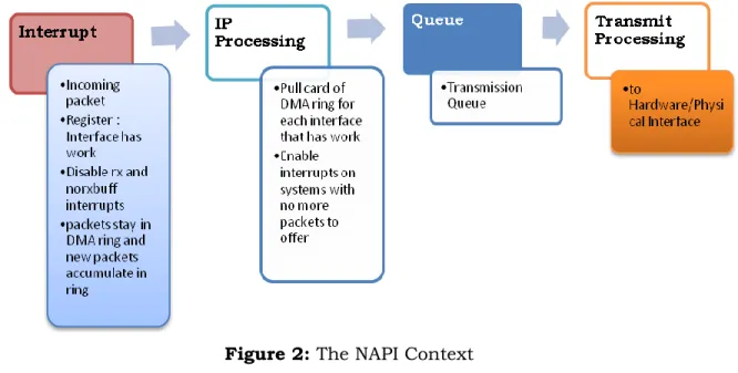
Figure 2: The NAPI Context NAPI works through:
(A) Interrupt mitigation
High-speed networking can create thousands of interrupts per second, all of which tell the system something it already knew: it has lots of packets to process. NAPI allows drivers to run with (some) interrupts disabled during times of high traffic, with a corresponding decrease in system load. Polling is an alternative to interrupt-based processing. The kernel can periodically check for the arrival of incoming network packets without being interrupted, which eliminates the overhead of interrupt processing. Establishing an optimal polling frequency is important, however. Too frequent polling wastes CPU resources by repeatedly checking for incoming packets that have not yet arrived. On the other hand, polling
22 | P a g e
too infrequently introduces latency by reducing system reactivity to incoming packets, and it may result in the loss of packets if the incoming packet buffer fills up before being processed. Given the same workload (i.e., number of frames per second), the load on the CPU is lower with NAPI. This is especially true at high workloads.
(B) Packet throttling
When the system is overwhelmed and must drop packets, it's better if those packets are disposed of before much effort goes into processing them. NAPI-compliant drivers can often cause packets to be dropped in the network adaptor itself, before the kernel sees them at all.
(C) More careful packet treatment, with special care taken to avoid reordering packets. Out-of-order packets can be a significant performance bottleneck.
(D) Balance between latency and throughput (E) Is independent from any hardware specifics
23 | P a g e
1.7 Disadvantages of NAPI
(1) In some cases, NAPI may introduce additional software IRQ latency.
(2) On some devices, changing the IRQ mask may be a slow operation, or require additional locking. This overhead may negate any performance benefits observed with NAPI
1.8 Linux Kernel and the new NAPI context
Linux Kernel and the new NAPI context packet processing mainly differ in the reception and the way of handling of the packets received. The following steps are followed when a packet is received:
(a) Packets are first received by the card. They are put in the rx_ring using DMA for recent cards. The size of the ring is hardware dependent. Older cards, which do not support DMA, use the PIO scheme: it is the host CPU which transfers the data from the card into the host memory;
(b) The card interrupts the CPU, which then jumps to the driver ISR(Interrupt Service Routine) code. Here arise some differences between the old subsystem and NAPI.
For the older subsystem, the interrupt handler calls the netif_rx() kernel procedure. netif_rx() enqueues the received packet in the interrupted CPU's backlog queue and schedules a softirq, responsible for further processing of the packet (e.g.TCP/IP processing). The backlog size can be specified in /proc/sys/net/core/netdev_max_backlog. When it is full, it enters the throttle state and waits for being totally empty to reenter a normal state and allow again an enqueue by calling netif_rx(). If the backlog is in the throttle state, netif_rx drops the packet. Backlog stats are available in /proc/net/softnet_stats: one line per CPU, the first two columns are
24 | P a g e
packets and drops counts. The third is the number of times the backlog entered the throttle state.
NAPI drivers act differently: the interrupt handler calls netif_rx_schedule(). Instead of putting the packets in the backlog, it puts a reference to the device in a queue attached to the interrupted CPU. A softirq is schedules too, just like in the previous case. To insure backward compatibility, the backlog is considered as a device in NAPI, which can be enqueued just as an another card, to handle all the incoming packets. netif_rx() is rewritten to enqueue the backlog into the poll_list of the CPU after having enqueued the packet in the backlog;
(c) When the softirq is scheduled, it executes net_rx_action(). Since the previous step differs between the older network subsystem and NAPI, this one does too. For older versions, net_rx_action pulls all the packets in the backlog and calls for each of them the ip_rcv() procedure or another one depending on the type of the packet: arp, bootp, etc. For NAPI, the CPU polls the devices present in his poll_list to get all the received packets from their rx_ring or from the backlog. The poll method of the backlog or of any device calls, for each received packet, netif_receive_skb() which roughly calls ip_rcv().
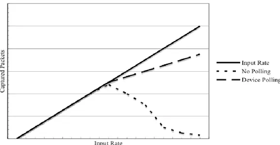
1.9 Packet Capture Performance (Polling Vs No polling)
It can be noticed from the graph that, as long as the system has enough CPU cycles to handle all the traffic, there is not much difference between the different setups [7]. However for non-polling systems there is a maximum full-capture speed after which the system spends most of the available cycles to handle interrupts leaving little time to other tasks, hence the packet loss.
25 | P a g e
Figure 3: Packet Capture Performance
Source: L.Deri, Improving Passive Packet Capture: Beyond Device Polling
1.10 Beyond Device Polling
Device Polling is not the ultimate solutions. The packet
capturing engines has to be designed with further considerations
(1) Design a solution for improving packet capture performance that is general and not locked to a specific driver or operating system architecture
(2) Device polling proved to be very effective; hence (if available) it should be exploited to improve the overall performance.
(3) For performance reasons, it is necessary to avoid passing incoming packets to the kernel that will pass then to userspace. Instead a straight path from the adapter to the user space needs to be identified in order to avoid the kernel overhead.
26 | P a g e 1.11 PF_RING
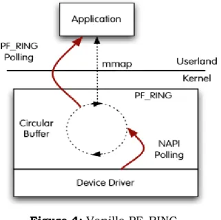
PF_RING is a type of network socket that improves the packet capture speed. PF_RING can be used with vanilla kernels (i.e. no kernel patch required); PF_RING is device driver independent, Kernel-based packet capture and sampling modules, which can be used for effective content inspection, so that only packets matching the payload filter are passed [8]. It also provides an ability to work in transparent mode in which the packets are forwarded to upper layers and the applications will work as usual. PF_RING polls packets from NICs by means of Linux NAPI. This means that NAPI copies packets from the NIC to the PF_RING circular buffer, and then the user space application reads packets from ring.
Figure 4: Vanilla PF_RING
Source: http://www.ntop.org/products/pf_ring/
PF_RING has three operational modes. Transparent mode 0 is the standard NAPI polling. Transparent mode 1, in which PF_RING-aware driver
27 | P a g e
copies the packets into PF_RING, while the same packet is passed to Linux kernel and Transparent mode 2, in which PF_RING aware driver copies the packets into PF_RING. Note that transparent mode 1 and 2 are meaningless on non PF_RING-aware drivers.
Advantage in this scenario is that PF_RING can distribute incoming packets to multiple rings (hence multiple applications) simultaneously. In this scenario, the drawback is that there are two poller‘s, both the application and NAPI and this results in CPU cycles used for this polling resulting in performance degradation.
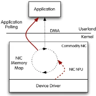
Figure 5: PF_RING with DNA driver
Source: http://www.ntop.org/products/pf_ring/
PF_RING DNA (Direct NIC Access) is a recent mechanism added to some
28 | P a g e
that packet copy from the NIC to the DMA ring is done by the NIC NPU (Network Process Unit) and not by NAPI [8]. This results in better performance as CPU cycles are used uniquely for consuming packets and not for moving them off the adapter.
The drawback is that only one application at time can open the DMA ring (note that modern NICs can have multiple RX/TX queues thus you can start simultaneously one application per queue), or in other words that applications in user space need to talk each other in order to distribute packets.
The main limitations are that, as NAPI polling does not take place in DNA mode, packet filtering is not supported as well as multi-core architecture is not completely exploited.
29 | P a g e
Chapter 2
Multi-core Architecture and 10G NICs with Multiple Hardware
Queue support (MSI-X)
2.1 Introduction
Network speeds have been increasing at an incredible rate, doubling every 3-12 months. This is even faster than one version of ―Moore‘s Law‖ which states that processing power doubles every 18-24 months; an observation made in 1965 which is still remarkably accurate. Moreover, although disk sizes have been increasing dramatically, disk and bus bandwidth have been increasing almost linearly; much more slowly than the exponential growth in other areas. In short, the disparity between network, CPU, and disk speeds will continue to increase problematically. 2.2 Today’s Multi-core Architecture
Today‘s COTS hardware offers features and performance that just a few years ago were only provided by expensive special purpose hardware. The desktop machines are becoming advanced core or even multi-processor parallel architectures capable of concurrently execute multiple threads at the same time. Modern network adapters feature several independent transmission (TX) and reception (RX) queues, each mapped on a separate core. Initially designed for facilitating the implementation of virtual machine supervisors, network queues can also be used to accelerate network traffic tasks, such as routing by processing incoming packets into concurrent threads of execution.
30 | P a g e
Although operating systems were adapted a long time ago to support multi-processing, kernel network layers have not yet taken advantage of this new technology. The result is that packet capture, the cornerstone of every network monitoring application is not able to capitalize of these breakthrough network technologies for traffic analysis, thus dramatically limiting its scope of application.
2.3 Load Balancing Technologies 2.3.1 Capture accelerators
Capture accelerators based on FPGA, implement filtering mechanisms at the network layer by means of rule sets (usually limited to 32 or 64) similar to BPF. Filtering runs at wire-speed. As the rule set is not meant to be changed at runtime, its scope of application is drastically limited [9]. Often traffic filtering is used to mark packets and balance them across DMA engines. Capture accelerators supporting multiple ring buffers implement in firmware the logic for balancing the traffic according to traffic rules, so that different processes or threads receive and analyze a portion of the traffic.
2.3.2 Receive Side Scaling
Intel‘s Receive-side scaling (RSS) is a network driver technology that enables the efficient distribution of network receive processing across multiple CPUs in multiprocessor systems. RSS enabled network adapters include the logic for balancing incoming traffic across multiple RX queues [9]. This balancing policy is implemented in hardware and thus RSS is not as flexible as rule based systems. However, this simple policy is effective in
31 | P a g e
practice also for network monitoring applications, as most of them though not bi-directional are flow-oriented.
2.4 Challenges in exploiting the Parallel Architectures
Primary concern in designing an optimized monitoring application lies in overcoming the challenges introduced by the parallel architecture under consideration.
2.4.1 General Challenges
(1) Packet capture applications are memory bound, but memory bandwidth does not seem to increase as fast as the number of core available.
(2) Balancing the traffic among different processing units is challenging, as it is not possible to predict the nature of the incoming traffic.
(3) Exploiting the parallelism with general-purpose operating systems is even more difficult as they have not been designed for accelerating packet capture.
(4) The operating system scheduler is completely unaware of the workload and in some cases it does not have the knowledge to relocate threads on the right core/processors.
(5) Balancing the workload among processors is not straightforward, as the workload depends on the incoming traffic, which cannot be predicted.
(6) Preserving the cache locality is a prerequisite in order to achieve a good scalability on modern parallel architectures and to overcome the bandwidth limitations.
32 | P a g e
2.5 Pitfalls in Monitoring Application Architecture
Though the commodity CPUs are providing more and more cores and the modern NICs are supporting multiple hardware queues that allow cores to fetch packets concurrently (in particular, this technology is known as
Receive Side Scaling, henceforward RSS), the current network monitoring
and security software is not yet able to completely leverage the potential which is brought on by the hardware evolution: even if progress is actually being made (multiple queue support has been included in the latest releases of the Linux kernel), much of current monitoring software has been designed in the pre multi-core era.
Figure 6: Design Limitation in existing Networking Monitoring Architecture Source: http://www.ntop.org/products/pf_ring/tnapi/
33 | P a g e
Though modern network adapters are trying to improve network performance by splitting a single RX queue into several queues, each mapped to a processor core and also to balance the load, both in terms of packets and interrupts, across all cores hence to improve the overall performance, the device drivers are unable to preserve this design up to the application: they merge all queues into one as it used to happen with legacy adapters featuring only one queue [10]. This limitation is a major performance bottleneck, because even if a userland application uses several threads to consume packets, they all have to compete for receiving packets from the same socket resulting in Single Resource Competition.
Competition is costly as semaphores or similar techniques have to be used in order to serialize this work instead of carrying it out in parallel, as happens at the kernel level. In multi-core systems, this problem is even worse because it is not often possible to map the monitoring application on the same core from which packets are coming. In addition the use of semaphores that, as a side effect, invalidates the processor‘s cache, which represents the basic ingredient for preserving multi-core performance. In a nutshell, current network layer design needs to ―merge and split‖ packets a couple of times and access them using semaphores, instead of providing a straight, lock-less path to the application with no performance limitation due to cache invalidation.
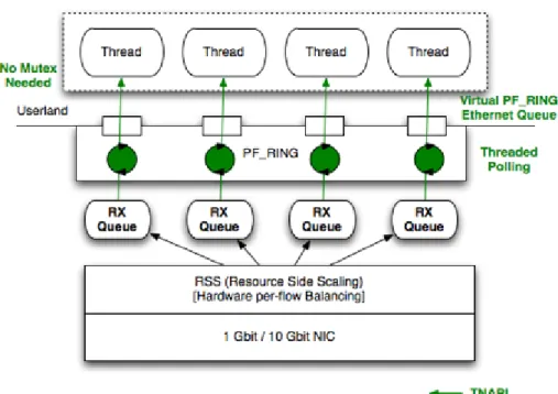
34 | P a g e 2.6 TNAPI
Figure 7: Multi-queue aware packet capture design Source: http://www.ntop.org/products/pf_ring/tnapi/
TNAPI overcomes the problems imposed by the normal monitoring architecture like
Distribute the traffic across cores for improving scalability.
Poll packets simultaneously from each RX queue for fetching packets as fast as possible hence improve performance.
Through PF_RING, expose the RX queues to the user space so that the application can spawn one thread per queue hence avoid using semaphores at all.
35 | P a g e
TNAPI achieves all this by starting one thread per RX queue. Received packets are then pushed to PF_RING (if available) or through the standard Linux stack. However in order to fully exploit this technology it is necessary to use PF_RING as it provides a straight packet path from kernel to user space [10].
Though TNAPI solves the problems faced by the existing monitoring modules, it is based on a heavily customized driver, which detaches parallel polling threads instead of relying on NAPI. Besides, its heavy use of kernel level polling leads to high CPU utilization.
36 | P a g e
Chapter 3
PFQ kernel module on multi-core architecture
3.1 Drawbacks of existing Monitoring Applications
Though the solutions proposed above have many advantages they all have some drawbacks in common (i.e.) either they don‘t exploit the parallel architecture properly or significant modification in existing device driver required and doesn‘t have beneficial improvement in case of vanilla drivers or High CPU Utilization.
3.2 PFQ
To overcome the disabilities encountered by existing packet capturing engines, a novel packet capturing engine, named PFQ is designed to allow efficient capturing and in-kernel aggregation, as well as connection-aware load balancing [11]. This engine is based on a novel lockless queue and allows parallel packet capturing to let the user-space application arbitrarily define its degree of parallelism. Therefore, both legacy applications and natively parallel ones can benefit from such capturing engine. PFQ outperforms its competitors both in terms of captured packets and CPU consumption.
PFQ is designed with an aim that allows parallelizing the packet capturing process in the kernel and, at the same time, to split and balance the captured packets across a user-defined set of capturing sockets. PFQ allows application writers to arbitrarily choose its level of parallelism, hiding within the kernel the full parallelism of the system. In particular, an
37 | P a g e
application can either use a single capturing socket (as in the case of legacy applications) or have PFQ balance incoming frames across a configurable set of collection points (sockets) or even use a completely parallel setup, where packets follow parallel paths from the device driver up to the application. In all of those cases, PFQ yields better performance than its competitors, while burning a lower amount of CPU cycles. Differently from many existing works for accelerating software packet processing, PFQ does not require driver modification (although a minimal few lines patch in the driver can further improve performance). Scalability is achieved through batch processing (which, in turn, leverages the hierarchical cache structure of modern CPUs) and through lockless techniques, which allow multiple threads to update the same state with no locking and minimal overhead. In particular, we designed a novel double buffer multi-producer single-consumer lockless queue which allows high scalability.
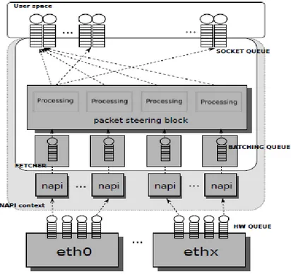
3.3 PFQ Packet Capturing Engine
PFQ Engine is made up of the following components: the packet fetcher, the de-multiplexing block and socket queues [11]. The fetcher dequeues the packet directly from the driver, which can be a standard driver or a patched aware driver, and inserts it into the batching queue. The next stage is the de-multiplexing block, which is in charge of selecting which socket(s) need to receive the packet. The final component of PFQ is the socket queue, which represents the interface between user space and kernel space. All of the kernel processing (i.e.) from the reception of the packet up to its copy into the socket queue is carried out within the NAPI
38 | P a g e
context; the last processing stage is completely performed at user space, thanks to memory mapping.
3.3.1 Driver Awareness
PFQ embodies a patched version of the ixgbe driver that just involves minimal code modifications (around a dozen lines of code); such a simple patch can be easily applied to new and existing drivers. This block is completely optional as PFQ shows good performance with vanilla drivers too.
This driver directly forwards the packet to the capturing module instead of passing it to the standard Linux networking stack thus improving performance. On the other hand, the capturing module has exclusive ownership of the packet, which is invisible to the rest of the kernel when at least one PFQ socket is open for monitoring a given device. Otherwise, the packet is forwarded to the Linux kernel and receives the classical default processing.
3.3.2 Packet Fetcher
The packet fetcher acts on every packet that is received. It receives the packets and inserts the associated pointer into its batching queue. Once such a queue (whose length is configurable) is filled, all of its enqueued packets are processed by the next block in a single batch [11]. Batch processing turns out to be more efficient in that, it improves the temporal locality of memory accesses, thus reducing the probability of both cache misses and concurrent access to shared data. In particular, a significant advantage comes from de-allocating packets in batches that, according to our measurements, can reduce the de-allocation cost by as much as 75%.
39 | P a g e
Notice that, as the packet is time stamped before queuing, this component does not influence timing accuracy.
3.3.3 Packet Steering Block
The steering block selects which sockets need to receive the captured packets. Although this is a single functional block, the steering processing is completely distributed and does not represent a serialization point. It uses a routing matrix to flexibly dispatch the incoming packets across multiple capturing sockets [11].
Figure 8: PFQ Architecture
Source: PFQ: a Novel Architecture for Packet Capturing On Parallel Commodity Hardware
40 | P a g e
In particular, such a matrix associates each reception queue of each handled card with one or more capturing sockets. Such sockets can be independent from each other (thus receiving one copy of the packet each) or can be aggregated into a load balancing group. In this latter case, a hash function is computed for each packet and only one socket in the balancing group is chosen. An additional advantage of such approach is the possibility of performing a bidirectional load balancing. As described in the previous section, RSS (Receive side Scaling) performs its native form of load balancing by computing a hash function over the 5-tuple of incoming packets. However, such scheme may not be appropriate for some applications, as RSS is not symmetric. For example, applications that monitor TCP connections need to observe packets from both directions which RSS would dispatch to different cores. For this reason, the packet steering block re-computes a symmetric hash function that will rebalance the packets with small overhead. Notice that load balancing and copy are not mutually exclusive: packets from the same hardware queue can be copied to a set of sockets and load-balanced across a different group. In greater detail, the de-multiplexing block is composed by a bit -field matrix and a load balancing function. The switching matrix stores, for each queue, a bitmap specifying which sockets have to receive its packets. Such a design allows dynamic insertion and removal of sockets with no need for mutexes on the fast data path allowing a great performance optimization. No serialization of threads of executions running on different cores is required.
41 | P a g e
3.3.4 Multiple Provider Double Buffer(MPDB) Socket queue
It is the last component of our architecture and the only one which is subject to inter-core contention. Our design shares some similarities with that of the FreeBSD zero-copy packet filter, but it improves the state of the art by introducing a wait-free solution which is optimized for a multi-core environment. Indeed, the whole mechanism implements a multiple producer - single consumer wait-free queue. The main components of this block are two memory mapped buffers: while one of them is being filled with the packets coming from the de-multiplexer, the other one is being read from the user application. The two buffers are periodically swapped through a memory mapped variable that stores both the index of the queue being written to and the number of bytes that have been already inserted (in particular, its most significant bit represents the queue index). Each producer (i.e. a NAPI kernel thread) reserves a portion of the buffer by atomically incrementing the shared index; such reservation can be made on a packet by packet basis or once for a batch. After the thread has been granted exclusive ownership of its buffer range, it will fill it with the captured packet along with a short pseudo header containing meta-data (e.g. the timestamp). Finally, it will finalize it by setting a validation bit in the pseudo header after raising a write memory barrier. Notice that, when the user application copies the packets to a user space buffer, some NAPI contexts may still be writing into the queue. This will results in some of the slots being half filled when they reach the application; however, the user-space thread can wait for the validation bit to be set. On the application side, the user thread which needs to read the buffer will first reset the index by specifying another active queue (so as to direct all subsequent writes to
42 | P a g e
it). Subsequently, it will copy to the application buffer a number of bytes corresponding to the value shown by the old index. Such copy will be performed in a single batch, as, from our past measurements, batch copy can be up to 30% faster. Alternatively, packets can be read in place in a zero-copy fashion.
3.4 PFQ Performance Analysis
In [11], performance of PFQ system was assessed under several configurations and it was mainly compared against PF RING because it was the obvious competitor for PFQ, in that it is a general architecture that increases the capturing performance with both vanilla and modified drivers. Two main performance metrics were taken into consideration: number of captured packets and average CPU consumption.
3.4.1 Experimental Setup
The testbed for experiments consists of two identical machines, one for generating traffic, and the other in charge of capturing. Both of them come with a 6 cores Intel X5650 Xeon (2.66 Ghz clock, 12Mb cache), 12 GB of DDR3 RAM, and an Intel E10G42BT NIC, with the 82599 controller on board. In order to test our system with the maximum degree of parallelism, we kept Intel Hyperthreading enabled, thus carrying out the experiments with 12 virtual cores. Due to the high cost of hardware based traffic generators and to the limited performance of software based ones, self written generators were used. It was able to generate up to 12 Millions minimum-sized packets per second. Lets us consider only the parallel setup and for any further reading refer to [11].
43 | P a g e
3.4.2 Parallel Setup
In this scenario each hardware queue is associated with its own user space thread, so that the processing paths of packets are completely parallel. Notice that in this scenario recently introduced quick mode option of PF_RING is used, which allows avoiding per-queue locks.
Figure 9: Complete parallel processing paths
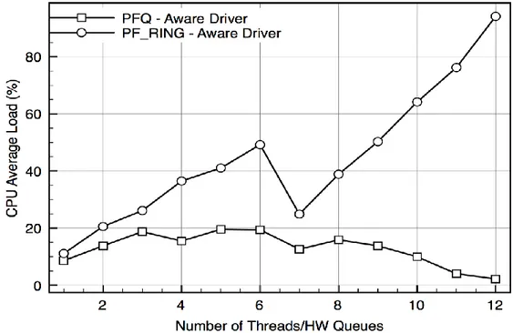
The results shown in figure 10 show that, although PF_RING manages to achieve good performance by preventing locking, PFQ still outperforms it. Besides, PFQ shows the same behavior with both vanilla and aware drivers (apart from a scale factor), while PF_RING only scales well with aware drivers.
44 | P a g e
Notice that PFQ is able to capture all of the incoming packets with 10 cores (its throughput steadies because there is no additional traffic to capture); unfortunately, our generator is not able to produce more input traffic and, therefore, we can only obtain a lower bound of PFQ's performance.
Figure 10: Complete parallel processing paths (CPU Consumptions)
From figure 11, we can understand the CPU utilization (in the case of aware drivers): while PF_ RING saturates the CPU, the global CPU consumption in the case of PFQ is roughly constant and well below 20%.
45 | P a g e
Chapter 4
PFQ Packet Filter Design and Implementation
4.1 What is Packet Filter?
When a packet reaches the interface, the node decides whether the packet belongs to it or it should be dropped in case it is not destined for it based on packet's header information. This is the basic routing principle. When packet filtering is added to routing devices, another level of packet analysis is done. Each packet will be put through the normal routing analysis and when determined that it has to be processed, the routing device applies the filter rules. Filter rules normally reflect security policies, which services are allowed, where they are allowed, which are not, which types of packets can reach a target device, which should be dropped, etc. So, packet filtering is the process of passing or blocking data packets, based on a set of user-provided rules, as they pass through a network interface. In recent years, with dramatically increasing network speed and escalating protocol complexity, packet filters have been facing intensified challenges posed by more dynamic filtering tasks and faster filtering requirements. However, existing packet filter systems have not yet fully addressed these challenges in an efficient and secure manner.
Packet filtering can also be defined as the selective passing or blocking of data packets as they pass through a network interface. Filter rules specify the criteria that a packet must match and the resulting action, either block or pass, that is taken when a match is found. Filter rules are evaluated in sequential order from first to last. Packet Inspection criteria‘s
46 | P a g e
are generally based on the Layer 3 and Layer 4 headers. The most often used criteria are source and destination address, source and destination port, and protocol(the so-called canonical 5-tuple).
Many versions of UNIX provide facilities for user-level packet capture, making possible the use of general purpose workstations for network monitoring. Because network monitors run as user-level processes, packets must be copied across the kernel/user-space protection boundary. This copying can be minimized by deploying a packet filter, which discards unwanted packets as early as possible. A packet filter can be implemented as a single predicate, that is a function returning a Boolean value on the basis of a set of filter rules when applied to a given packet. If the value of the function is true the kernel copies the packet for the application; if it is
false the packet is discarded.
Because network monitors often want only a small subset of network traffic, a dramatic performance gain is realized by filtering out unwanted packets in interrupt context. Thus, if the packet is not accepted, only those bytes that were needed by the filtering process are received by the host.
Packet filtering techniques have evolved over time in order to cope up with the increasing speed of the interface and increasing traffic rate.
4.2 Filtering Techniques
Filter rules normally reflect security policies, which services are allowed, where they are allowed, which type of packets can reach a target device, which ones should be dropped, etc. So, packet filtering is the process of passing or blocking data packets, based on a set of user-provided rules, as they pass through a network interface. There are many
47 | P a g e
approaches to packet filtering. As the main focus of this thesis is on traffic monitoring, we are merely interested in packet filtering as a simple function that drops/accepts packets out of a network interface. Several filtering techniques are well known in literature: some of the most frequently used filtering approaches are BPF, CMU Filter and Dynamic Packet Filter.
4.2.1 CMU/Stanford Packet Filter
CMU/Stanford Packet Filter (CSPF) is the first user-level packet filter. For the existing computers in that era, CSPF performed efficiently and provided flexibility in the environment, with an interpreter based filter mechanism. The specified filter language is stack based, and operates on binary expressions as well as Boolean operators. It uses a tree model to configure its filter engine. It believes that user-level de-multiplexing will incur more context switches and inter-processes. In order to provide both flexibility and efficiency, CSPF specifies filter in user-level and processes in kernel-resident using a specific packet field as a key. The problem of this approach is the bottleneck in operations that has a data structure of 16-bit words array.
4.2.2 The BSD Packet Filter
The BSD Packet Filter (BPF) is a more efficient interpreter than CSPF. It is an interpreter based on a register-based filter mechanism. BPF with register-based and assembly-like language can access more instructions, multiple registers, one input data and a scratch memory. It uses a computationally equivalent directed acyclic control flow graph, in order to avoid redundant computation [14]. It learns packet parse states in
48 | P a g e
the graph, so it reduces some paths and comparisons. It also uses a Boolean expression tree. The major performance improvements of BPF comparing to CSPF, are due to architectural improvements (registered based RISC CPU).
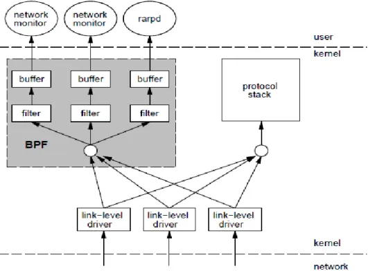
When a packet arrives at a network interface the link level device driver normally sends it up the system protocol stack. But when BPF is listening on this interface, the driver first calls BPF.
Figure 11: BPF Architecture
Source: The BSD Packet Filter: A New Architecture for User-level Packet Capture
49 | P a g e
BPF feeds the packet to each participating process filters. This user-defined filter decides whether a packet is to be accepted and how many bytes of each packet should be saved. For each filter that accepts the packet, BPF copies the requested amount of data to the buffer associated with that filter. The device driver then regains control. If the packet was not addressed to the local host, the driver returns from the interrupt. Otherwise, normal protocol processing proceeds.
4.2.3 Just in Time BPF
Similar to the normal BPF, but it adds a just-in-time compiler into the kernel to translate BPF code directly into the host system's assembly code. The simplicity of the BPF machine makes the JIT translation relatively simple; every BPF instruction maps to a straightforward machine instruction sequence. There are a few assembly language helpers which help to implement the virtual machine's semantics; the accumulator and index are just stored in the processor's registers. The resulting program is placed in a bit of vmalloc() space and run directly when a packet is to be tested. A simple benchmark shows a 50ns savings for each invocation of a simple filter - that may seem small, but, when multiplied by the number of packets going through a system, that difference can add up quickly.
4.2.4 Dynamic Packet Filters
Dynamic Packet Filter (DPF) approaches are currently the state of the art in the packet filtering world. DPF provides the most wanted flexibility of packet filters and the speed of hand-crafted demultiplexing routines. DPF filters are the fastest packet filters available. DPF achieves
50 | P a g e
high performance by using a carefully-designed declarative packet filter language that is aggressively optimized using dynamic code generation. The declarative packet filter language is used by protocols to describe the message headers that they are looking for.
4.3 Linux Packet Filter
Functioning of a Linux packet filter can be explained in a nutshell as follows [3]
Creates a special-purpose socket (i.e., PF_PACKET)
Attach a BPF program to the socket using the setsockopt system call Sets the network interface to promiscuous mode with ioctl
Read packets from the kernel, or send raw packets, by reading/writing to the file descriptor of the socket using
recvfrom/sendto system calls
Sample Usage:
static void attach_filter(void) { struct sock_fprog filter;
if ((sock = socket(PF_PACKET, SOCK_RAW, htons(ETH_P_ALL)))== -1) {
(void)fprintf(stderr, "Error: %s\n", strerror(errno)); exit(4);
}
if (ioctl(sock, SIOCGIFFLAGS, &req) == -1){
(void)fprintf(stderr, "Error: %s\n", strerror(errno)); exit(4);
51 | P a g e }
req.ifr_flags |= IFF_PROMISC;
if (ioctl(sock, SIOCSIFFLAGS, &req) == -1){
(void)fprintf(stderr, "Error: %s\n", strerror(errno)); exit(4);
}
filter.filter = bpf_code; filter.len = FT_LEN;
if (setsockopt(sock, SOL_SOCKET, SO_ATTACH_FILTER, &filter, sizeof(filter)) == -1){
(void)fprintf(stderr, "Error: %s\n", strerror(errno)); exit(4);
}
return; }
4.4 PFQ Packet Filter
Packet filtering module in PFQ Engine is located right after the NIC (Network Interface Card) in order to drop unnecessary packets before being copied into kernel buffer. The aim of this thesis is to implement a bank of bloom filters for the PFQ in order to speed up packet processing by discarding unwanted packets.
4.5 Bloom Filter
As the speed of the network interfaces are increasing drastically, a fast, time and space efficient strategy is required to check whether a rule is
52 | P a g e
defined on a particular interface or not to speed up packet filtering. Bloom filter is a space-efficient probabilistic data structure for group membership query. It is widely used in network monitoring applications which involve the packet header/content inspection. To provide fast membership query operation, this data structure resides in the main memory in most of its applications. Each membership query consists hashing for a set of memory addresses and memory accesses at these locations. The space efficiency is achieved at the cost of a small probability of false positive, that is, an element may be announced as in the set while it is not. By exploiting the probabilistic nature of this data structure, the probability of false positive, i.e., false positive rate, is usually very small and outweighed by the space saving.
In Bloom filters, False positives are possible, but false negatives are not; i.e. a query returns either "inside set (may be wrong)" or "definitely not in set". Elements can be added to the set, but not removed (though this can be addressed with a counting Bloom filter). More the elements are added to the set, the larger the probability of false positives. The size of the bloom filter is to be selected in such a way that the false positive is below a certain level. 4.6 Working of Bloom Filter
A Bloom filter consists of a bit array of m bits, which are all initially set to 0. Adding the elements of a set S = {x1, x2 , ….. xn } of n elements is
done as follows. For each element xi that is added, k different hash
functions h1, …., hk each with a range {1,…,m} are used to calculate k
different hash values h1(xi),…..hk(xi). We assume that these hash functions
53 | P a g e
bits hj(xi) are set to 1, for j = 1, 2, …., k. The bits in the Bloom filter can be
set to 1 multiple times, but only the first time this has effect.
For example, consider a bloom filter of 8 bits which is all set to zero at the startup. Consider two hash functions h1 and h2 which returns values
between 1 and 8 inclusive. Given an element y=4 to be inserted, hashing using both the functions h1 and h2 are done.
0 0 0 0 0 0 0 0
Figure 12: Empty Bloom Filter of 1 byte width
Let us suppose that h1(y)=4 and h2(y)=2 , then bit 4 and 2 are set in
the bloom filter indicating that the membership of the element is marked. Similarly consider the insertion of another element say z=6. Let‘s suppose that the result of hashing is h1(z)=7 and h2(z)=4 .
0 1 0 1 0 0 1 0
Figure 13: Bloom Filter after insertion of element y and z
It can be noted that, though h1(y) = h2(z) = 4, it is set only once. If a
bit is set once, setting it again doesn‘t have any effect. Once an element is inserted into the bloom filter it cannot be removed which signifies that, a bit set in the bloom filter cannot be cleared because some other element might have set the same bit as a result of hashing during its insertion.
54 | P a g e
When we want to check if a certain element is in our Bloom filter, a similar approach is used as during the addition of elements. The same k hash functions are calculated over the element y. Then we test if the bits hi(y) for i=1, 2, …., k are equal to 1. If one or more of these bits are still 0,
the element is certainly not in the set. If all bits are 1, the element was probably in the set, although there is a small probability that the tested bits were set to 1 due to the addition of different elements. Then we have a false positive.
For example, suppose we search for the element x. we perform the hash of x and we get h1(x) =2 and h2(x) =7. After checking the bloom filter to
determine whether the corresponding bits are set or not, we find that they are set. It means x may be present because there may be some other element which could have set these bit positions. In this case these bits are set by y and z. From this we can clearly say that there is some probability of false positive but false negative can never occur in the bloom filter which is an important feature of bloom filter.
An interesting property about Bloom filter is that, any Bloom filter can represent the entire universe of elements. In this case, all bits are 1. Another consequence of this property is that add never fails due to the data structure "filling up." However, the false positive rate increases steadily as elements are added until all bits in the filter are set to 1, so a false response is never returned. At this point, the Bloom filter completely ceases to differentiate between differing inputs, and is functionally useless.