Università di Pisa
Corso di Dottorato di Ricerca in
Ingegneria Meccanica
Development of a Residual Lifetime
Prediction Methodology for Creep and
Fracture Behaviour of Ferritic-Martensitic
Steels using Small-Punch Testing
Technique
Allieva:
Ing.Phys. Darina Todorova BLAGOEVA
Tutori:
Prof. Roger C. HURST - JRC - Institute for Energy, EC Prof. Leonardo BERTINI – D.I.M.N.P., Università di Pisa Prof. Marco BEGHINI – D.I.M.N.P., Università di Pisa
VII Ciclo
SOMMARIO
Lo scopo principale della tesi consiste nel dimostrare l'applicabilità delle prove di “Small-Punch” (SP) per la stima della vita residua di materiali metallici operanti ad alta temperatura. La mancanza di normalizzazione di questa tecnica e dubbi sulla correlazione dei dati con quelli ottenuti da test di scorrimento viscoso convenzionali, giustifica l’utilizzazione del “Code of Practice for SP Testing” (CEN/WS 21). Il lavoro presente e' in particolare dedicato ad investigare le proprieta' di scorrimento viscoso delle saldature di acciao P91 alla temperatura di 600oC assieme con proprieta' di frattura a basse temperature. Dischi sottili, di 8 mm di diametro e 0.5 mm di spessore, sono stati fabbricati estratti da diverse zone di un componente in P91 contenente una saldatura: metallo base (BM), materiale esposto all’ambiente (SE), saldatura (WM), zone termicamente alterate sia a grana fine che a grana grossa (FG-HAZ & CG-HAZ). I risultati delle misure di scorrimento viscoso sui dischi, ottenuti a 600oC sotto differenti carichi consistentemente secondo il “Code of Practice”, si possono correlare con i dati ottenuti attraverso prove standard di scorrimento viscoso. Le misure di SP dimostrano di fornire un metodo solido per descrivere il comportamento di queste leghe e saldature e il modello di scorrimento viscoso derivato, utile per predizione di vita residua, che potrebbe essere anche dimostrato attraverso FEA per la stima delle deformazioni da scorrimento viscoso dei dischi. Addizionalmente, il metodo SP dimostra alto potenziale per la valutazione delle proprieta’ di frattura per saldature P91, in particolare per stimare la temperatura di transizione fragile-duttile e la resistenza alla frattura.
ABSTRACT
The main aim of the thesis is to demonstrate the suitability of Small Punch (SP) testing for lifetime prediction of metallic materials operating at high temperatures. The lack of standardisation of this technique and doubts about the correlation of the data with that obtained from conventional creep tests, supports the need to exploit the recently launched Code of Practice for Small Punch Testing (CEN/WS 21). The present work is specifically concerned with investigating the creep behaviour of P91 steel weldments at 600oC along with low-temperature fracture behaviour. Thin discs, 8mm in diameter and 0.5mm thick, were manufactured from different zones of a component containing a P91 welded joint: base metal (BM), service exposed material (SE), weld metal (WM), fine-grain and coarse-grain heat affected zones (FG-HAZ & CG-HAZ). The results of SP creep tests on these disks, performed at 600oC under different loads carefully following the Code of Practice, could be correlated with standard creep data. The SP test is shown to be a reliable method to depict creep behaviour of this alloy and its weldments and a creep model derived, useful for life time prediction, could also be demonstrated through FEA to predict the creep deformation of the SP discs. Additionally, the SP testing method shows potential to evaluate the fracture properties of P91 weldments, in particular the ductile-to-brittle transition temperature and fracture toughness estimations.
Acknowledgments
The author is grateful to Prof. R. HURST from the Joint Research Centre (JRC) - Institute for Energy (IE) EC, Prof. L. BERTINI and Prof. M. BEGHINI from D.I.M.N.P. (Mechanical Department) of the University of Pisa for their fruitful constructive guidance and helpful advice; to Dr. G. DE SANTI , Director of JRC-IE for providing facilities; to Dr. L.DEBARBERIS and Dr. N.TAYLOR from JRC-IE for the collaborative management support; to Prof. P. HAEHNER, Dr. F. Di PERSIO, Dr. E. PAFFUMI from JRC-IE, Dr. Y. LI from KEMA (Netherlands) and Dr. Ph. Tipping from HSK (Switzerland) for their consultative cooperation; and to Dr. F. HUKELMANN, Ph. MINNEBO, R. Ch. RAMOS, J. MENDES, R. VAN DER AAT, S. RIPPLINGER, F. HARSKAMP, R. SMIT, A. PFRANG, E. CONCEICAO and M. WALLENDORF for the good teamwork, collaboration and technical support.
CONTENT
1. INTRODUCTION ... 11
2. LITERATURE REVIEW ... 15
2.1 Creep damage: An industrial problem... 15
2.2 Creep ... 16
2.2.1 An introduction to creep ... 16
2.2.2 Stages of creep ... 16
2.2.3 Mechanisms of Creep Deformation... 17
2.2.4 Power law approach... 19
2.2.5 Mechanisms of creep fracture ... 20
2.2.5.1 Cavity nucleation………..20
2.2.5.2 Cavity growth……….21
2.2.5.3 Initialisation of discrete cracks………23
2.3 Ferritic / Martensitic (F/M) steels for elevated temperature
applications... 23
2.3.1 Power Generation Industry applications... 24
2.3.2 Nuclear applications ... 26
2.4 P91 steel... 26
2.5 Microstructural evolution of P91 steel and its weldments... 27
2.5.1 Microstructural phases in P91 base material... 28
2.5.2 Thermal processing of P91 steel ... 29
2.5.3 Creep behaviour and related microstructural changes for P91 steel... 30
2.5.4 P91 weld material... 32
2.5.5 P91 weldment under creep conditions ... 34
2.6 Miniaturized Testing Technique ... 35
2.6.1 Current industrial needs ... 35
2.6.2.1 Miniature specimens similar in shape and form to the conventional
specimens but scaled-down in absolute size………36
2.6.2.2 Miniature specimens innovatively developed in order to take advantage of the small size………..38
2.6.3 Indentation techniques ... 40
2.7 SP testing method background... 41
2.8 Code of Practice for Small Punch Testing ... 43
2.9 Conclusions from the literature review ... 44
3. THESIS OBJECTIVES... 45
4. EXPERIMENTAL ... 46
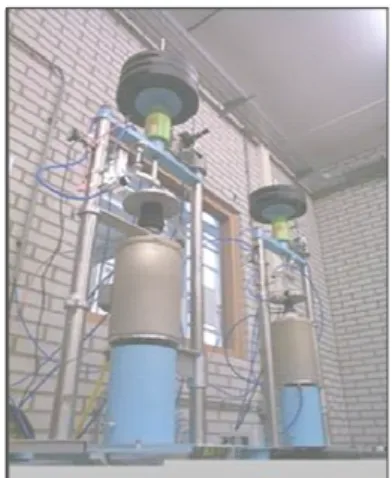
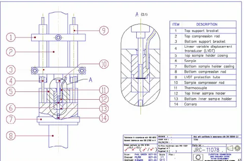
4.1 Testing equipment ... 46
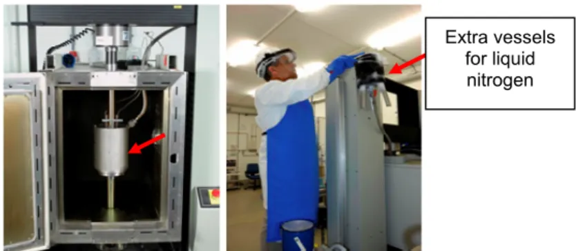
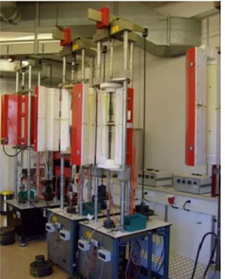
4.1.1 SP Creep facilities ... 46
4.1.2 SP fracture test facilities... 51
4.1.3 Uniaxial creep equipment... 55
4.1.4 Uniaxial Tensile Equipment... 56
4.2 Materials & Specimens ... 57
4.2.1 Small Punch Specimens ... 57
4.2.1.1 LICON material sampling………57
4.2.1.2 INTEGRITY material sampling………...58
4.2.2 Uniaxial Specimens... 60
4.2.2.1 Uniaxial Creep Specimens………..60
4.2.2.2 Uniaxial Tensile Specimens………61
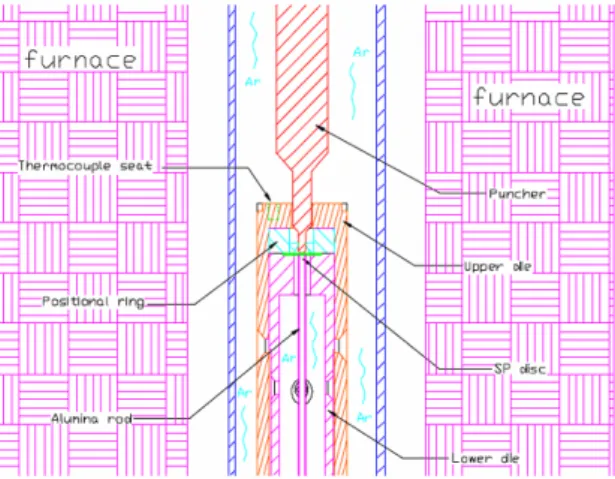
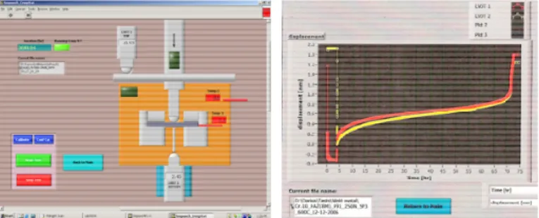
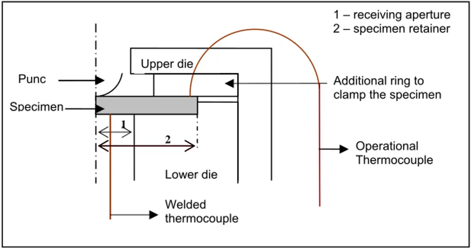
4.3 Small Punch Test Set-up ... 62
4.3.1 Small Punch Creep Test Set-up... 62
4.3.2 Small Punch Fracture Test Set-up ... 65
5. RESULTS & DISCUSSION... 67
5.1 Creep Results ... 67
5.1.1 Conventional Uniaxial Creep Results... 67
5.1.1.2 INTEGRITY Uniaxial Creep Results………..69
5.1.1.3 Stress-rupture results for uniaxial creep tests………..73
5.1.2 Small Punch Creep (SPC) Results... 74
5.1.2.1 LICON SPC Results……….75
5.1.2.2 INTEGRITY SPC Results………75
5.1.3 Comparison between uniaxial and SP curves ... 80
5.1.4 Stress/load dependence of the minimum strain/deflection rate.. 81
5.1.5 Time dependence of the minimum (strain/deflection) rate ... 83
5.1.6 Stress-Rupture results: comparison between uniaxial and SPC test results ... 85
5.1.6.1 P91 Base Metal & Service Exposed material………..85
5.1.6.2 Welded P91 material………88
5.2 FE Modeling of SPC test... 93
5.3 Small Punch Fracture (SPF) Results ... 99
5.3.1 Ductile-to-Brittle Transition Temperature (DBTT) evaluation ... 103
5.3.2 Fracture toughness JIC and KIC evaluation ... 107
5.3.2.1 Ductile behaviour………109
5.3.2.2 Brittle behaviour………..111
5.3.2.3 Comparing the KIC (JIC) values with literature data………...112
5.3.2.4 Comparing the SP JIC values for BMI, SE and WMI ……….115
6. CONCLUSIONS ... 117
ABREVIATIONS
AC1 Lower Critical Transformation Temperature AC3 Upper Critical Transformation Temperature ASME American Society of Mechanical Engineers ASTM American Society for Testing and Materials
BM Base Metal
BML Base Metal LICON
BMI Base Metal INTEGRITY
CT Compact Tension
CEN European Committee for Standardization CG-HAZ Coarse Grain Heat-Affected-Zone CWA CEN Workshop Agreement CoP Code of Practice
CVN Charpy V-Notch
DBTT Ductile-to-Brittle Transition Temperature
EC European Commission
ECCC European Collaborative Creep Committee EPERC European Pressure Equipment Research Council
EU European Union
FATT Fracture Appearance Transition Temperature
FE Finite Element
FG-HAZ Fine Grain Heat-Affected-Zone
F/M Ferritic/ Martensitic
HAZ Heat-Affected-Zone HB/ HV/ HRC Hardness Brinell/ Vickers/ Rockwell HTR High Temperature Reactors
IC-HAZ Intercritical Heat-Affected-Zone IE Institute for Energy
JRC Joint Research Centre
LSE Lower-Shelf Energy
NDT Non-Destructive Testing NPP Nuclear Power Plant
PWHT Post Weld Heat Treatment
SE Service Exposed
SEM Scanning Electron Microscopy
SP Small Punch
SPC Small Punch Creep
SPF Small Punch Fracture
TE Transition Energy
USE Upper-Shelf Energy
UWS University of Wales Swansea
WM Weld Metal
WMI Weld Metal INTEGRITY
WML Weld Metal LICON
NOTATIONS
A Elongation
E Young’s modulus
ν Poisson’s ratio
σ Stress
σ0.2 Yield stress defined at 0.2% plastic strain
UTS Ultimate tensile strength δ Deflection in SPC test
R Radius of the disc receiving hole r Radius of the punch indenter ho Initial disc thickness
hf Final disc thickness
t Thickness of the gauge-block
•
ε
sCreep strain rate
•
δ
sCreep deflection rate tr Time to rupture
M Monkman-Grant constant
n Stress exponent in the uniaxial creep test n* Force exponent in the SP creep test Ψ = n/n* Stress/ force exp ratio
p Time exponent in uniaxial test p* Time exponent in SP test Φ = p/p* Time exp ratio
εpl Plastic strain
JIC (KIC) Fracture toughness
ESP SP fracture energy εf (εqf) Fracture strain
u m Maximum deflection (displacement) in SPF test
u* Displacement at fracture in SPF test Fm Maximum force in SPF test
σf SP Fracture stress in SPF test
TSP DBTT measured by SPF test
1. INTRODUCTION
There is an increasing worldwide demand in the power-generation, metals and chemical process industries for efficiency improvements, together with safe, economic and reliable operation, and this forms the primary focus in today's rapidly evolving energy market. As a consequence, in the last two decades, there was a need for the service pressure and temperature of components for advanced power plants to be increased significantly and more severe requirements on strength, corrosion resistance and creep properties were imposed on high temperature steels. Such higher working temperatures and pressures allow increased thermal efficiency thereby lowering fuel consumption and environmental impact. Unfortunately elevated operating temperatures and pressures tend to accelerate material degradation of the working components.
During the exploitation period a number of degradation mechanisms such as temper embrittlement, creep, hydrogen attack and hydrogen embrittlement can impair plant integrity. The damage subsequently may lead to initiation and propagation of defects into cracks and eventual failure. Creep is a common degradation mechanism when high temperatures are employed, e.g. HTR (high temperature reactors), boilers, piping, steam generators, gas turbine engines, oil refineries and petrochemical plants. All these systems possess some components that will experience creep. An understanding of high temperature materials behaviour is beneficial in mitigating failures in these types of systems.
Many industries are faced with an increasing array of ageing plant and equipment, in many cases close to or even beyond original design life. The capacity, efficiency and safety of plants depend critically on the integrity of the components and materials employed. Thus, it is crucial to evaluate the degradation processes due to long-term service exposure with higher accuracy in order to ensure integrity of the power plants and further to extend their life. Possibility of failure and remanent life-time assessments are critical issues in the safety analysis of the current industrial plants. Besides the safety, another important aspect is the economical advisability to extend the life time of the existing components beyond their design life rather than to build new plants. This requires increasing innovation in material testing and research to provide improved remaining life analysis.
Initially the design life was based on some empirical assumptions and experience in materials and technologies developments, implementing an appropriate safety factor. As a generality, the design of plant components and safety performance assessment of materials used for high temperature applications in the power generation, nuclear, petrochemical, chemical process and other such industries is currently based on their tensile and creep rupture strength. Service experience has shown that the present design codes are very conservative. The conservatism in the design, the use of more sophisticated procedures/codes and careful husbandry of components may reduce the safety factor while maintaining safety and frequently allows life to be extended beyond that originally intended.
At the same time however, the question concerning the uncertainty in the evaluation and monitoring of the residual life of plant components is of great importance for the industry. Some uncertainty comes from using the nominal properties of the materials instead of their residual mechanical properties, due to lack of enough experience and knowledge. The historical recording of use is the basis for reliable assessment of the remaining value and reuse possibilities of technical equipment and tools. In addition, residual lifetime prognosis helps to fix guarantee terms for reused components. Obtaining information on the mechanical condition of service exposed components however can be problematic because of the need to sample significant quantities of material for testing direct from the component. The traditional destructive testing methods require large specimens that would violate the structural integrity of the working components.
The shortage of enough material to be sampled non-invasively rarely permits material evaluation by conventional and well standardised test techniques. In this case Non-Destructive Testing (NDT) is applicable in order to identify damage and irregularities in materials. NDT often provides the only method of obtaining information about the current 'health' of process plant. To address this problem, various non-destructive or miniaturised specimen innovative testing techniques have been developed over the past two decades.
The small punch (SP) technique is considered an almost non-destructive technique, requiring a small amount of material, easy to carry out and relatively inexpensive. The SP method, proposed by Manahan et al. [1], enjoys an increasing interest lately and can be applied for studies of creep [37, 38, 191] and fracture properties [174], as well as fatigue, ageing embrittlement, hydrogen embrittlement [213] and irradiation damage [104]. The small specimen size of this test technique – discs of 0.3-1mm thickness and 5-10mm diameter, can eliminate the need for large amount of material removal, while at the same time permitting measurement of properties in key local areas of components.
Beyond the considerable success and promising results, however, there is no doubt that technical limitations still exist for the SP technology. Such limitations are the reduced specimen size, and thereby potential oxidation effects, and how non-representativeness of the sampled material could influence the test results to a much stronger extent than is the case for conventional creep testing. The ability of the “small-scale” tests to reproduce data from full sized specimens and their range of applicability is still open for discussion. These aspects remain a concern and much work needs to be done in order to convince industry to have the necessary trust to heed the results of such testing. In spite of this, interest in the technique is on the increase and an effort for possible wide adoption by industry is timely. The late efforts on standardisation and some doubts about the correlation of the data with that obtained from conventional creep tests, provide strong arguments for further investigations in this direction.
A ferritic-martensitic steel 9Cr-1Mo, standardized as Grade P91 in ASTM in the early 80’s, and its weldments have been investigated in the thesis. Because of the excellent creep rupture strength values of this steel it is used worldwide by many engineering companies, boiler builders, piping companies and utilities. P91 steel is
a candidate material for Generation IV nuclear power plants (in-core and out-of-core applications), as well as for fusion applications. Thin discs, 8mm in diameter and 0.5mm thick, produced from different zones of a full repair weld between P91 fresh and P91 service exposed material, were tested following the Small Punch Testing Code of Practice for creep and fracture properties evaluation. All tests were performed following tightly the guidelines given in the Code of Practice (CoP) for SP testing or CEN Workshop Agreement CWA 15627 [2], published in December 2006.
Why is this work timely and topical?
¾ Several authors published results on the SP creep testing of P91 base metal. However, the accumulated results are not sufficient and most of them are based on accelerated short-term test that could be a source of discrepancy and inaccuracy. Moreover, mainly empirical correlations between the SP results and those obtained by conventional creep tests were developed. The thesis proposes a linear relationship between the stress [MPa] applied in the conventional uniaxial creep test and the load [N] applied in the SP method; thus, offering a direct correlations between the SP creep results and the conventional creep results over an extended test duration (up to approximately 4300h).
¾ Very limited data are reported in the literature on SP creep testing of P91 weldment material, particularly the coarse- and fine-grain heat-affected-zone, known to be the most critical zone in the weldment. The research conducted compares the SP creep strength values obtained from homogeneous HAZ material with the creep strengths of the other zones of the weldment: BM, WM and SE material.
¾ Variety of specimen geometries and testing equipment is used by different researchers for SP creep testing. The work conducted here tends to unify the results acquired from different equipments, particularly the puncher radius, the radius of the receiving hole where the disc lies, and the sample thickness, by comparing the thesis results with results obtained by other authors. All these quantities participate in the relationship establishing the stress/load ratio, proposed in the CoP. Additionally this relationship takes into account also the ductility of the material, which turns out to be an important issue when a broader stress interval is applied. In this sense, the stress/load relationship has not only a purely empirical, based on testing geometry, but also a physical meaning depending on the material itself and the testing condition. Hence, the study is also to support the published CoP for the SP testing.
¾ Published results on low temperature SP testing used for fracture properties evaluation, particularly the ductile-to-brittle transition temperature and fracture toughness, are incomplete or simply missing. Although it was not the main subject of the thesis, an important progress has been achieved in conducting SP fracture tests over a wide
temperature range, down to cryogenic temperatures, establishing correlations between the SP data and the data obtained by conventional Charpy and fracture toughness test and, as well as, recommendations for future work in this direction.
In conclusion, the present thesis tends to prove that the SP testing methodology can be a promising method for the evaluation of creep properties and that in future it might be used as “stand alone” method giving the opportunity for creep strength measurements, especially for very small areas of the components where using conventional creep samples is not an option.
As far as the fracture properties are concerned, it could be said that the thesis provides preliminary but pioneering results in this research sphere, which can be used as a basis for future investigations.
2. LITERATURE REVIEW
The literature review introduced below, aims to provide a comprehensive background to the subject treated in this thesis work, namely: applicability of the Small Punch testing methodology for predicting the long-term creep-rupture behaviour of advanced ferritic/martensitic (F/M) steel, in particular P91 steel. Reference to the current industrial needs and future requirements, especially with regards to the high temperature production processes, will be made in the present review. An overview on the life time assessment techniques and creep damage from a physical point of view, as well as the evolution of the ferritic/martensitic steels for high temperature applications will follow. Finally an introduction to the state of the art of the Small Punch testing technique and its potential as a reliable non-destructive integrity assessment method will be presented and objectives of the current study will be formulated.
2.1 Creep damage: An industrial problem
There is an increasing worldwide demand in the power-generation, aircraft, metals and chemical process industries for improvements in the efficiency, utilisation and longevity of high-temperature components, which may be subjected to creep, fatigue and creep-fatigue loading and environmental attack, leading to the degradation of their material properties over an extended period of time. Improvement of the thermal efficiency of power generation Plants is an important issue from the viewpoint of energy saving, environmental conservation (carbon dioxide emissions) and economy. This can be achieved by elevating operating temperatures and pressures, which would however accelerate material degradation of high-temperature components. It is crucial to evaluate their degradation due to long-term service exposure with higher accuracy to ensure integrity of the power plants and further to extend their life.
Creep and stress rupture is one of the root cause failure mechanisms for industries associated with high temperature operations such as HTR (high temperature reactors), boilers, piping, steam generators, gas turbine engines, oil refineries and petrochemical plants. All these systems possess components that experience creep.
An understanding of high temperature materials behaviour is beneficial in evaluating failures in these types of systems. The damage subsequently leads to initiation and propagation of defects into cracking and eventual failure. Failure of a component indicates it has become completely or partially unusable or has deteriorated to the point that it is not dependable or unsafe for normal sustained service which could then lead to unwanted damages in terms of human life and economics. Low failure rates of components, vehicles, plants, and any technical object are highly important for human lives, environment and capital invested. At the same time, strong international competition compels the reduction of life-cycle costs of products.
In order to reduce the down time and increase the overall efficiency of the plant, it is essential to look into the mechanics of failure and its after effect on the life to failure. Though a well-planned maintenance programme can prevent catastrophic
failures there is still considerable interest in the development of techniques for assessing the remanent life of critical components.
Nowadays, the European Commission together with other representatives of the universities, industry and research and technology organizations are putting more and more efforts in developing unified European Codes treating component design and plant integrity assessments. Developing of one such Code of Practice [2] for plant integrity assessment using small punch creep testing requires high level technical input but once it is developed and becomes standardised and routine, it is economically worthwhile. This emerging technology is to be promoted by standardisation in order to become a widespread tool for a variety of industrial equipment owner/operators and maintenance and integrity assessment service providers that presently have the problem of choosing between complex expensive techniques, or inexpensive yet poor NDT methods in routine work.
2.2 Creep
2.2.1 An introduction to creep
Creep is the term given to the material deformation that occurs as a result of long term exposure to levels of stress even below the yield strength. The rate of this damage is a function of the material properties and the exposure time, exposure temperature and the applied load (stress). Depending on the magnitude of the applied stress and its duration, the deformation may become so large that a component can no longer perform its function.
The evaluation of creep behaviour is one of the most important factors to assess the integrity of elevated temperature structural components. Creep is usually a concern to engineers and metallurgists when evaluating components that operate under high stresses and/or temperatures. Creep is not necessarily a failure mode, but is instead a damage mechanism. Rather than failing suddenly with a fracture, the material permanently strains over a longer period of time until it has to be replaced or finally fails. Creep does not happen upon sudden loading but the accumulation of creep strain in longer times causes deterioration of the material. This makes creep deformation a "time-dependent" deformation of the material. Creep deformation can be obtained in rather rapid time frames under very high temperatures, i.e. temperatures around half of the melting temperature. Plastics and low-melting-temperature metals may creep at room temperature (cold flow), and virtually any material will creep upon approaching its melting temperature. Since the relevant temperature is relative to melting point, creep can be seen at relatively low temperatures depending upon the alloy. This deformation behaviour is important in systems for which high temperatures are endured, such as conventional and nuclear power plants, jet engines, heat exchangers etc.
2.2.2 Stages of creep
The test techniques which serve to evaluate the creep properties of materials generally are based on uniaxial test loading parallel to the longitudinal axis of a cylindrical or plate specimen. The basic parameters recorded are the dependence of the creep strain ε (or rather extension) versus time. The load is constant and it is applied to a tensile specimen maintained at a constant temperature. Strain is then
measured over a period of time. Experimental studies of creep behaviour have produced strain-time curves exhibiting four characteristic segments, as illustrated schematically in Figure 2.1.
¾ Instantaneous strain due to loading, εo
¾ Primary or transient creep - stage I – deformation takes place and the resistance to creep increases until stage II - decreasing strain rate to a steady state level.
¾ Secondary or steady-state creep - stage II - it is this regime that is most well understood. The "creep strain rate" is typically the rate in this secondary stage. The stress dependence of this rate depends on the creep mechanism.
¾ Tertiary creep - stage III - occurs when there is a reduction in cross-sectional area due to necking or effective reduction in area due to internal void formation. The tertiary stage onset is marked by exponential increase in the strain rate ultimately leading to rupture.
Fig.2.1 Schematic representation of a creep curve 2.2.3 Mechanisms of Creep Deformation
There are several different creep regimes, depending mainly on the temperature, where different mechanisms are applied. The temperatures between which creep deformation mechanisms are operating are usually expressed as a fraction of the melting temperature TM, expressed in degrees absolute. The different regimes
roughly cover the temperature ranges 0-0.5 TM, 0.5-0.9 TM, and 0.9-1.0 TM:
¾ Lower range creep regime: T < 0.5 TM
It includes the so-called “logarithmic creep” so named due to the nature of the equation describing the creep strain accumulated at low temperatures [3].
ε = α1loge(α2t+1) (2.1)
where α1 and α2 are constants and t is time.
¾ Upper range creep regime: T > 0.9 TM
In this high temperature range the factor controlling the creep rate is mainly linked to diffusional flow of vacancies. Creep by diffusion of vacancies (diffusion creep) is somewhat similar to flow in liquids. Vacancies are point defects, and they tend to
favour grain boundaries that are normal, rather than parallel, to the applied stress Vacancies tend to move from regions of high to low concentrations.
Diffusional flow can occur at low stresses but, usually, it requires high temperatures. In this temperature range and at stresses too low for dislocation processes to be significant, a mechanism known as Nabbaro-Herring creep operates [4].
Nabarro-Herring (N-H) creep is a process by which dimensional changes of the material are caused by atom-vacancies or defects exchange through the lattice. This form of creep is also known as bulk diffusion.
However, vacancy diffusion involving stress directed vacancy flow through the grain matrix and along preferred paths, such as grain boundaries, has also been reported at lower temperatures and is known as Coble creep (Figure 2.2).
Fig.2.2 Diffusional creep
¾ Intermediate range creep regime: 0.5 Tm <T< 0.9 Tm
This is the temperature range in which most engineering materials operate and in which creep may cause concern to the engineers. At high stresses creep is controlled by the movement of dislocations. This is the so called “dislocation
creep”. Dislocations are line defects. They may move in a conservative fashion,
retaining their length, or they move in a non-conservative fashion - increasing their length through atomic diffusion. The former process is known as 'glide'. Typically dislocation glide is opposed by obstacles – other dislocations, solute atoms or precipitates, grain boundaries, etc. The later process is known as 'climb’ (Figure 2.3).
Fig.2.3 Dislocation creep
The different creep deformation mechanisms can combine. A Deformation Mechanism Map is schematically presented in Figure 2.4.
Grain boundary sliding is sometimes considered as a separate mechanism which
Fig.2.4 Deformation mechanisms map 2.2.4 Power law approach
The creep at intermediate temperatures is often explained in the literature as a process, involving competing strain hardening and thermal recovery processes, commonly known as "recovery creep". In the recovery creep theory, the steady state creep is assumed to be a major part of the plastic creep deformation process and
ε
•s =dε/dt value is used to describe the curve as a whole and can becalculated from the slope of the secondary stage in the time-strain creep curve (Figure 2.1). The onset of the secondary creep stage is characterised by thermally driven dislocation annihilation processes, which initiate the effects of strain hardening. Permanent plastic strain rate is reached at the point of equilibrium between these two processes.
Temperature, together with the stress, are fundamental factors influencing material deformation under creep conditions. The steady state creep rate can be expressed as:
•
ε
s = f(σ,T) (2.2)This can be rewritten as
•
ε
s = u(σ).v(T) (2.3)where u(σ) describes the variation of έs with stress at constant temperature and v(T) describes the variation of έs with temperature at constant stress. Thus, the
stress dependence of the secondary creep rate at intermediate stresses and at the same temperature can be expressed in terms of a power law:
•
ε
s ∝ σn (2.4)where “n” is a stress exponent, obtained from plotting “log σ” against “log έs”.
This is often called "Norton's Law". Values of “n” in the intermediate stress range can be ~ 4-5 for a pure metal and between 5 and 40 for more complex materials [5,6].
The temperature dependence is no surprise, since it is quite clear that creep is a thermally activated phenomenon and variation of έs with temperature at the same
level of stress can be expressed in terms of an Arhenius rate type equation. The Arhenius model predicts failure acceleration due to temperature increase. This empirically based model takes the form:
•
ε
s ∝ -(Qc/RT) (2.5) Ewhere Qc is the activation energy for creep and R is the gas constant (= 8.314
J/mol K). For pure metals and single phase alloys Qc is approximately equal to the
activation energy for self diffusion. In more complex polycrystals and alloys, Qc
values twice that of self diffusion activation energy values have been reported [7,8]. These equations can be combined to give a simple power law approach applicable at temperatures and stresses to be found in common engineering applications.
•
ε
s = Aσnexp -(Qc/RT) (2.6)where A is a constant and T denotes the temperature measured in degrees Kelvin (273.16 + degrees Celsius) at the point when the failure process takes place. The rupture time is inversely proportional to the creep rate:
tr (∝1/
•
ε
s) = A’σ-nexp(Qc/RT) (2.7) 2.2.5 Mechanisms of creep fractureAs it was discussed above, at high temperatures, the application of a stress leads to a creep deformation resulting from:
¾ Motion of dislocations (dislocation creep);
¾ Mass transport by diffusion (diffusion creep) - dominant at lower stress levels; or
¾ Grain-boundary sliding process.
These processes in turn lead to a distribution of internal stresses that may relax on removal of the stress. In the metals it is associated with the un-bowing of pinned dislocations, rearrangement of dislocation networks, and local grain-boundary motion.
Creep rupture can be considered as a consequence of the following process: ¾ Damage accumulates in form of internal voids (cavity nucleation); ¾ Voids appear on grain boundaries normal to the tensile stress;
¾ Atoms diffuse from the void surfaces into grain boundaries and voids grow (formation and growth of stable cavities);
¾ Voids grow faster and faster, until they link, leading to creep fracture (initialization of discrete cracks).
2.2.5.1 Cavity nucleation
When a metal is loaded to a stress level below the yield stress, it undergoes immediate elastic deformation but, initially, does not deform plastically because the dislocations in the metal are pinned by a variety of obstacles. The obstacles include dislocation pile-ups, grain boundaries, precipitates, twin boundaries, alloy and impurity atoms and other microstructural defects in the metal lattice. Further, the metal may make plastic adjustments by dislocation motion in regions of stress
concentrations and high interstitial concentrations (stage 2). These regions include grain boundaries, the metal adjacent to inclusions, precipitates and second phase particles and lattice regions near microscopic cracks and notches.
During tertiary creep (stage 3), damage accumulates in the form of internal voids on grain boundaries normal to the tensile stress. Atoms diffuse from void surface into grain boundaries, and voids grow at an increasing rate inside the material until they link, leading to creep fracture (Figure 2.5).
Fig.2.5 Diagram showing voids growing and coalescence
2.2.5.2 Cavity growth
Early concepts of cavity growth and development were proposed at the beginning of the 90s [9,10]. Although these models are now known to be inaccurate, they highlighted the early need for models of cavity behaviour. Initial models of cavity growth based on the continued sliding of grain boundaries were not popular as they predict that the cavity shape will be irregular. Work on creep cavity growth has shown cavities to be rounded or ellipsoidal in appearance, which suggests that diffusion processes contribute to cavity growth [11].
Numerous theories have proposed that cavities on boundaries experiencing a tensile stress may grow by the direct absorption of vacancies generated in a similar manner to diffusional creep [12-14].
Early work by Hull and Rimmer [12] showed that the activation energy for grain boundary diffusion was half that of the activation energy for lattice self diffusion. This was considered evidence for diffusion mechanisms occurring in cavity growth. They concluded that grain boundary cavity growth was due to the diffusion of surface atoms to the surrounding grain boundaries under the action of an applied stress. This Hull and Rimmer model was refined by other workers who found that the finite diffusion rate of the atoms at a cavity tip was no longer sufficient to maintain a rounded cavity if the stress levels, and thus deformation rates, were sufficiently high. Thus, while diffusional growth models may be applicable at low stresses, the broad based acceptance of diffusion models has now lessened. Current models are based on the generally accepted premise that creep cavity growth is controlled by the creep rate. Models range from cavity growth associated with localized deformation in grain boundary regions [15]to those assuming growth by vacancy absorption but with the growth rate constrained by the deformation rate in the surrounding material [16,17]. This constrained cavity growth model depends on the fact that the ability of a grain boundary to cavitate not only relies on its orientation to the tensile axis but also on the properties of the boundary itself i.e. low or high-angle boundaries. Thus, cavitation may occur on a boundary but the adjacent boundaries may be undamaged, surrounding the grain with a 'shell' of
un-cavitated boundaries [18,19]. Now the voids can only grow on un-cavitated boundaries at a rate governed by the creep rate of the surrounding grains [20-22].
It is also possible to link the deformation rate of a material to the growth of creep cavities. Within the material, a dislocation moving along its glide plane is stopped when it reaches a grain boundary which doesn't contain its glide plane. If the applied stress is maintained, the dislocation can continue moving by a combination of glide and climb. The resulting non-conservative climb events emit vacancies. The role of these emissions will depend on the normal stress causing climb as well as the shear stress causing sliding. The result of an injection of vacancies at the grain boundary is that the cavity opens and grows. The dislocation also may have crossed the grain interior by a glide mechanism, thus contributing to the grain deformation as it went. It can be seen from these processes that the arrival of dislocations from the lattice to the grain boundary can govern the processes involved in cavity growth. Thus the growth of cavities can be linked to the deformation rate of the material instead of diffusional processes. The motion of dislocations within the lattice as seen in creep controlled mechanisms can be used to explain the dependence of rupture life on creep rate, known as the “Monkman-Grant relationship” [23].
M = έs.tf (2.8)
where M is a constant.
It is generally agreed that the creep fracture of low alloy Cr-Mo steels is the result of grain boundary cavity and inter-granular crack formation, and this has been shown over a wide range of testing conditions [24-27].
However controversy exists as to when in the creep life of a two phase alloy the creep cavities contribute to the acceleration of the creep rate. Some workers have reported the formation of cavities during the initial stages of creep [28], while others have claimed an incubation or threshold for cavity nucleation [28, 29]and that the time at which cavities first appear can be at any stage during the secondary or tertiary creep regimes. Other more recent work [24] on low alloy steel has found intergranular cavities to be absent during secondary creep, except in regions near the specimen surface. This effect was clearly visible in large specimen where it could be distinguished from general cavitation. Further evidence from ex-service low alloy components has shown creep cavitation damage of the type which has led to service failure to develop only late in the service life under service conditions [30, 31].
Work by Cane on low alloy steels [25,32] performing tests with failure lives of ~1000 hours showed that failure occurred as a result of high localised strains in the vicinity of carbide particles. This work was later expanded to conclude that the nucleation of these creep cavities occurred mainly at grain boundary particles, specifically sulphides and that the carbides remained coherent [24,30].
Failure can occur by one of two mechanisms, first proposed by McLean [33], depending on the applied stress. At low stress levels, the fracture is due to inter-granular cavitation linkage. At higher stresses, the stress level is high enough to produce stress concentrations and so initiate triple point cracking. This change in mechanism was reported by Cane to be linked to a change in rupture mode from a low ductility 'brittle' inter-granular form at low stress to high ductility failure at high stresses involving considerable plasticity of the matrix material [26]. This work
would seem to be supported by the findings of Parker and Wilshire who observed mechanical instability and necking in high stress creep tests on low alloy steels [24].
2.2.5.3 Initialisation of discrete cracks
The development of wedge type cracks and cavity nuclei during creep is illustrated in Figure 2.6. Wedge or triple point cracking is the result of sliding on grain boundaries experiencing shear stresses which lead to a stress concentration sufficient to develop cracks on the boundary normal to the tensile axis (Figure 2.6(a)). A minimum applied stress is required to initiate the triple point crack. Thus this cracking mode is only observed at relatively high stresses.
Fig.2.6 Diagram illustrating the development of: a) Wedge cracks; and (b) Four types of cavity nucleation
The nucleation of cavities at lower stresses is generally agreed to be as a result of grain boundary sliding being impeded by a range of grain boundary irregularities (Figure 2.6(b)):
¾ The interaction of a slip band with a grain boundary- sliding then produces a ledge;
¾ The interaction of a sub-grain with a grain boundary- sliding then produces a cusp;
¾ Particle fracture or de-coherence of particles sat on grain boundaries.
2.3 Ferritic / Martensitic (F/M) steels for elevated temperature
applications
In the last two decades the service pressure and temperature of components for advanced power plants increased significantly and more severe requirements on strength, corrosion resistance and creep properties were imposed on high temperature steels. These are the factors that typically determine the thermal efficiency of the unit. Higher working temperatures allow increased thermal efficiency that lowers the fuel consumption and environmental impact [34]. Thus, an important aspect in current energy production is to find a compromise between the most economical and environmentally friendly solutions to keep plants competitive in the market. To comply with the requirements for improved efficiency for operation up to 650°C and higher steam pressures than used in the past and reduced CO2 emission, the classical materials must be replaced by the new high-
Cr progressive creep resistant steels, whose development and verification are still ongoing [35-44]. These materials are predominantly martensitic, with varying amounts of retained delta-ferrite. Materials with F/M microstructures are preferred
because of their favourable physical properties such as good thermal conductivity and low coefficient of thermal expansion coupled with higher resistance to thermal shock. These are some of the advantages over austenitic stainless steels. For these reasons there has been a great demand for high strength and heat resistant chromium ferritic and F/M steels which has resulted in the development and application of several variants.
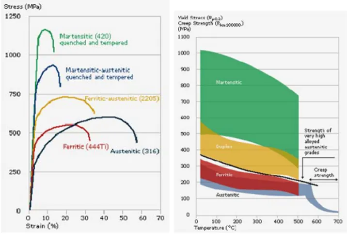
The difference in the mechanical properties of different steels: martensitic and F/M, ferritic, ferritic-austenitic, austenitic; is perhaps seen most clearly in the stress-strain; tensile & creep strength curves below (Figure 2.7):
Fig.2.7 Stress-strain curves, tensile & creep strength curves for various steel grades
The toughness of the different types of stainless steels shows considerable variation, ranging from excellent toughness at all temperatures for austenitic steels to the relatively brittle behaviour of martensitic steels (Figure 2.8). Toughness is dependent on temperature and generally improves with increasing temperatures. Martensitic, ferritic and ferritic-austenitic steels are characterised by a transition in toughness, from tough to brittle behaviour, at a certain temperature, the transition temperature.
Fig. 2.8 Fracture toughness curves for various steel grades 2.3.1 Power Generation Industry applications
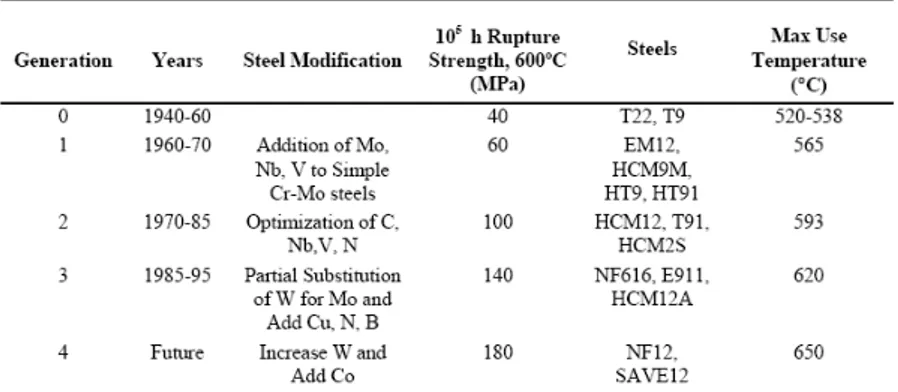
The first Cr-Mo steels were used for conventional power-generation applications in the 1920s. The 2¼Cr-1Mo designated by ASTM as Grade 22, was introduced in the 1940s and is still widely used today. Along with Grade 22, 9Cr-1Mo (T9) was in early development - the additional chromium added for corrosion resistance. Since then, there has been a continual push to increase operating temperatures of conventional fossil-fired power-generation systems. This led to the development of
several “generations” of steels with improved elevated-temperature strengths (Table 2.1). The evolution of steel compositions, which began with T22 and T9 (zeroth generation) with 100,000 h creep-rupture strengths at 600ºC of about 40 MPa, has allowed for increased operating steam temperatures and pressures [45-48].
Three generations of steels have been introduced since the introduction of T22 and T9, and a fourth generation is in the development stage. Steels beyond the zeroth generation contained mainly 9–12% Cr for improved corrosion and oxidation resistance for elevated temperature operating conditions.
The first generation, in addition to increased chromium, involved primarily the addition of the carbide formers vanadium and niobium to T22 and T9 compositions to add precipitate strengthening. In some cases, a small tungsten addition was made for further solid solution strengthening, in addition to that provided by molybdenum. These steels, introduced in the 1960s for applications to 565ºC, included 2¼Cr-1MoV, HT9, HT91, and EM12. These steels allowed to increase the 105 h rupture strengths at 600ºC up to 60 MPa.
Table 2.1 Evolution of F/M Steels for Power-Generation Industry
For the second generation, developed in 1970–1985, carbon, niobium, and vanadium were optimized, nitrogen was added, and the maximum operating temperature increased to 593ºC. The new steels included modified 9Cr-1Mo grade P91/T91 and HCM12, which has a duplex structure (tempered martensite and δ-ferrite). These steels have 105 h rupture strengths at 600ºC of about 100 MPa. Of these latter steels, P91/T91 has been used most extensively in the power-generation industry throughout the world [45-48].
The third generation of steels was developed based on the previous generation, primarily by the substitution of tungsten for some of the molybdenum, although boron and nitrogen were also utilized. They were developed and introduced in the 1990s for 620ºC operation with 105 h creep rupture strengths at 600ºC of 140 MPa. Finally, the next generation of steels is being developed at present, where the intention is to push operating temperatures to 650ºC. These fourth-generation steels, SAVE12 and NF12, differ from the previous generation primarily by the use of up to 3% cobalt; they have projected 105 h creep-rupture strengths at 600ºC of 180 MPa [45-48].
2.3.2 Nuclear applications
The expected increasing world-wide demand for energy in the XXIst century has spurred international cooperation to consider ways to meet energy needs while maintaining and improving the environment. This has led naturally to nuclear energy, since it can be produced without the environmental effects that accompany the use of coal or petroleum products. Although renewable energy sources offer the possibility of clean energy, there are concerns about economic efficiency and reliability, whereas the economic reliability of nuclear energy has been demonstrated by the reactors operating today. Rather than relying on the present generation of reactors, an international collaboration is directed toward developing a new generation (Generation IV) of reactors that will produce abundant, reliable and inexpensive energy. For several Gen IV reactors concepts, because of the high temperatures envisioned (up to 650ºC and higher), F/M steels are contemplated as possible structural and/or cladding materials. The primary emphasis is on the high-chromium (9–12% Cr) steels.
Although there are uncertainties concerning the long-time stability and creep properties of the third and fourth generation of the 9–12% Cr Martensitic steels, there appears to be no question that there are significant improvements over the first- and second-generation steels, at least for ≈100,000 h based on present experimental data from which lifetimes are extrapolated. Given the increased operating temperatures of the new reactor designs, steels with increased elevated-temperature strength will be required if the advantages of F/M steels are to be available to the reactor designer. It should be noted that for some in-core applications (e.g. cladding) the service lifetimes are very much less than the ≈300,000h envisioned for conventional power plants.
2.4 P91 steel
The modified 9Cr-1Mo steel was chosen for the thesis. This steel generally costs less than austenitic alloys so the economic incentive to use this material can be significant depending on the specific application. The enhanced properties like lower thermal expansion coefficient, higher thermal conductivity, and improved oxidation resistance at intermediate temperatures, would enable steam-plant components to be manufactured with thinner walls, thus they would minimize thermally induced stresses. With the addition of niobium, vanadium, and nitrogen, the “standard” 9Cr-1Mo also exhibited a substantial increase in creep-rupture strength, compared to traditional steels, thus giving birth to the known today “modified” 9Cr-1Mo – Grade T91 for tubing and Grade P91 for headers and piping. Modified 9Cr-1Mo containing niobium and vanadium, was developed in the USA [49] and standardized as T/P91 in ASTM in the early 80s. The advantages of this material have been recognized in many countries by engineering companies, boiler builders, piping companies and utilities with the result that grade 91 is being installed in many power stations worldwide. P91 steel is a candidate material for Generation IV nuclear power plants (in-core and out-of-core applications), as well as for fusion applications. The excellent creep rupture strength values allow the optimum use of this material in the temperature range from 540oC to 600oC.
Compared with the conventional material (T/P22) considerable wall thickness and weight reductions are possible and have been realized in many cases.
The creep properties of 9% Cr steels have been widely investigated in Europe, USA and Japan by very long tests in the range 550-650oC [50]. However, P91 steel has been in use, in a limited number of plants, since the late 80s /early 90s, and that although the steam temperatures in most of these older units were between 540 - 565°C (below the maximum design temperature of 600oC for this steel), there have been some disturbing reports about P91 failures [51]. These failures are a matter of concern especially because they occurred at lower temperatures than the maximum design temperature of 600°C for such steels and the present operating temperature of up to 590°C in some of the new higher efficiency European and Japanese plant where 9Cr martensitic steels have been introduced more recently [51-55].
The grade 91 material can also be used with substantial technical and economical advantages in the case of refurbishment of old piping systems by the new material. By the end of this decade, hundreds of power plants will be built or refurbished. Whether old or new, much of the pipe that carries the high-pressure steam to the turbines is now made from a newer alloy. This newer grade, 9Cr-1Mo (P91) steel, offers a much better strength-to-weight ratio than "the old standby" P22 steel.
2.5 Microstructural evolution of P91 steel and its weldments
For the long term application of the new steels, it is necessary to evaluate the microstructure changes that are likely to occur during service and to assess the effect of such changes on the high-temperature creep behaviour. Evaluation of the microstructural changes in service exposed material is fundamental for a correct characterisation of material condition and predicting the service extension terms. For ferritic steels the main aspects of the microstructural evolution relevant to the creep exposure period are:
¾ Microstructural phase evolution;
¾ Formation of microvoids at grain boundaries; ¾ Carbide evolution;
¾ Interparticle spacing.
The phase evolution aspect is related mainly to the temperature effect and not so strictly connected to the load application. It can be expressed as: tendency to martensite spheroidization; coarsening of precipitates in the ferritic matrix and at grain boundaries; and broadening of denuded zones (no precipitates) along grain boundaries [56]. Formation of micro-voids at grain boundaries is based on the fact that creep damage mechanisms are related to the appearance of cavities some time before the rupture occurs. These cavities gradually form micro-cracks by interlinkage that leads to rupture initiation. The size and density of the cavities increase as creep progresses from secondary to tertiary. Material type also influences the cavities’ size significantly, however it is in the microns range – the reason they are called "micro-voids" or "micro-cavities".
Many studies have been carried out on the evolution of carbides present in the steels during creep exposure. Separation and coarsening of carbides is in general an index of material degradation due to damage progress. Presence of different classes of carbides in steel is related to the global composition and thermal
process applied in manufacturing. Some studies [57] revealed the possibility to establish a correlation between carbide composition and exposure time for defined temperature. However, because of the large scatter of the microstructural related parameters, these equations in theory can be applied for residual life time estimation, but they are not standardised yet.
Interparticle distance concept is related to the carbide coarsening phenomena and grain boundary area denudating. Creep curve calculation theoretical models based on interparticle distance and carbides coarsening have been developed in the early eighties and compared to the experimental creep test data [58,59]. These models are based on changing of creep rate (tertiary creep) due to particle coarsening. 2.5.1 Microstructural phases in P91 base material
The modified 9Cr-1Mo alloy is an advanced material whose mechanical properties depend on the creation of a precise microstructure, and the maintenance of that microstructure throughout the component’s service life. The optimum chemical composition with its low carbon content results in good fabricability and weldability (Table 2.2).
C Si Mn P S Cr Mo V Nb Ni N
wt,% 0.1 0.27 0.53 0.007 0.01 9.0 0.91 0.2 0.04 0.35 0.0038
Table 2.2 Chemical composition of P91 steel
The superior properties of P91/T91 hinge on a precise addition of vanadium (V), niobium (Nb) and nitrogen (N), and a carefully controlled normalizing process to produce a complete phase transformation from austenite into martensite. This produces hard steel with high tensile strength at elevated temperatures and high creep resistance. Next, a controlled tempering process must follow, to allow the V and Nb elements to precipitate – as carbides and carbon nitrides – at defect sites in the microstructure. This serves to anchor or “pin” the defect sites, thereby holding the microstructure in place. Most recently the importance of the V and Nb additions and their precipitating action was reported by Takashi Onizawa [60] and others, at the ECCC Creep Conference, held in September 2005 in London by the European Collaborative Creep Committee. Mo is a solid-solution strengthening element; Cr is to increase the corrosion resistance, and N is a carbo-nitride precipitates former.
The microstructure of P91 steel – tempered martensite formed during a final normalizing and tempering heat treatment is presented in Figure 2.9. After normalising at 1050oC air cooling leads to martensitic transformations due to the
chromium content. Tempering in the range 730-780oC leads to improved ductility
and toughness, and induces formation of carbides and carbo-nitride precipitates (strengthening precipitates). Secondary microstructural phases identified in P91 steel are: M23C6 Cr-carbides and MX (V, Nb)-nitride particles (Figure 2.10) that
precipitate in the steel during tempering, on prior austenite grain boundaries, ferrite subgrain boundaries and on dislocations inside subgrains (Figure 2.11). Further particles precipitation like intermetallic (Fe,Cr)2(Mo) Laves phase might be
observed when the steel is put into operation in power plant at temperatures below the final tempering temperature.
Fig.2.9 P91 microstructure – base material (optical left, TEM micrographs right) [61]
Fig.2.10 Phases identified in P91 steel: (a) Morphology and distribution of secondary phase particles, (b) TEM-micrograph of Laves phase, carbon extraction
replica, and (c) TEM-micrograph of M23C6 and MX particles, carbon extraction replica [62]
Fig.2.11 SEM micrograph showing microstructure of P91 steel – tiny precipitates both on grain/ subgrain boundaries and on former martensitic laths [63]
2.5.2 Thermal processing of P91 steel
“Thermal processing” is an important issue and refers to any heating process that has the potential to alter the microstructure of the material. Problems that can significantly impair the creep-rupture strength of these alloys are over-tempering, under-tempering, and exposure to temperatures in the intercritical region.
Over-tempering causes a coarsening of critical precipitates, with a corresponding loss in creep-rupture strength because of the loss of the restraining influence of these precipitates. Under-tempering also can endanger the high-temperature
properties, since the required precipitation does not go to completion, and the precipitates either are absent or are of insufficient size to stabilize the structure. Other complications associated with under-tempering – such as the risk of brittle fracture and stress-corrosion cracking - also must be considered.
Fig.2.12 Phase diagram for high- and low- Cr Steel
Perhaps the most common problem with Grade 91 is post-production exposure to temperatures in the intercritical region – above the temperature where the tempered martensite begins to transform back into austenite (referred to as the lower critical transformation temperature or AC1) and below the temperature where phase transformation is complete (the upper critical transformational temperature, AC3). When Grade 91 is heated into this intercritical region, the material partially re-austenitizes, and the resulting structure will have substantially reduced creep-rupture strength (Figure 2.12). In the worst case, this material will have lower creep-rupture strength than that of traditional Grade 22.
Thus, the two important parameters for Grade 91 components are:
¾ Lower critical transformation temperature (AC1), above which the alloy’s phase transformation from martensite back into austenite begins, which was found between 800oC and 830oC (depending on the chemical composition) , and
¾ Upper critical transformation temperature (AC3), above which the phase transformation to austenite is complete, which was found between 890oC
and 940oC.
2.5.3 Creep behaviour and related microstructural changes for P91 steel
The foreseen life for a power plant may be 40 years as the average creep rate is about 10-11s-1. However to make an extrapolation to this rate from rates measured in the standard laboratory creep testing is risky and we need to understand the physical processes involved. At low rates of creep deformation (low stresses – up to about 100MPa) the transport of matter occurs by migration of vacancies rather than by the glide of dislocations. These creep processes are usually classified as viscous creep [64, 65].
Upper critical temperature AC3
Lower critical temperature AC1
Ferrite and Iron carbide Austenite
The technically applicable stresses and temperatures for creep testing for P91 steel are in the range 300MPa/500oC – 50 MPa/650oC. The rupture times with loading conditions in this range are between 100 and 300,000 hours and the minimum creep rates – between 3.10-6 and 5.10-12s-1. In the author's opinion [61] in this stress/temperature range the creep mechanism is dislocation creep. Generally speaking, the combination of pressure and high temperature makes the dislocation based creep process the dominant damage mechanism. Creep deformation sources are the migration of dislocations and sub-grain boundaries [66,67].
By alloying the creep properties are improved with precipitation of stable carbides and nitrides. These particles will obstruct moving dislocations and will slow down the creep rate. At lower temperatures the Orowan mechanism (Figure 2.13) can be used to explain the strengthening of hard impenetrable particles.
Fig.2.13 Orowan mechanism: a) bowing between particles;
b) Bypassing the particles, thus leaving dislocation loop surrounding each one
In this mechanism, the dislocation bends between the particles leaving a dislocation ring about each particle (Figure 2.13). At higher temperatures the particle strength according to Orowan will overestimate the contribution since the increase in dislocation climb mobility at high temperatures allows climb across particles. A model for dislocation climb around particles has been developed in [68, 69].
Thus, the improved creep strength of P91 steels, as for all 9-12% Cr steels, is due to the mechanisms which retard the migration of the dislocations and sub-grain boundaries, and consequently delay the accumulation of creep strain with time. Such mechanisms consist of:
1) Solid solution strengthening due to formation of solute atoms clouds around the dislocations; and
2) Precipitate strengthening due to interactions with particles.
The solution strengthening effect often is referred to the presence of Mo. During high temperature creep exposure at 600-650oC, most of the Mo in the steel precipitates as intermetallic Laves phase and thus the solution will become poor in Mo. The dominating opinion is that forming of Laves phase would cause creep instability in the steel, since the precipitation strengthening effect from Laves phase was believed to be insignificant.
However, it has been made clear recently that long-term microstructure stability is not influenced significantly by the solid solution strengthening from Mo. The most important strengthening mechanisms for 9-12% Cr steels including P91 steel is believed to be precipitation hardening by pinning of dislocations and sub-grain boundaries. Thus the microstructure stability under creep load will be equivalent to precipitate stability [70,71]. Precipitates are known to retard recovery and
recrystallisation [72-74]. Further more it is recognised that altering the particle distribution by varying the heat treatment procedure can have a marked effect on the creep properties of these alloys. As a result, several theories have been proposed to predict the effects of variations in particle size and spacing on creep behaviour [75-77]. Threadgill and Wilshire [78] proposed that during creep of precipitate hardened alloys with constant volume fractions of precipitates, small particles are sheared so that the work done in cutting each particle increases and the creep rate decreases with increasing particle size.
In P91 steel, unlike the low alloy ferritic steels operating in the creep regime, the more easily visible changes such as spheroidisation and break down of the microstructure at a scale that can be seen under an optical microscope does not occur in P91. This means that much more costly transmission electron microscopy (TEM) has to be used to identify changes in the microstructure. Even then the changes may not be visible to a non-specialist, as it is mainly the changes in the precipitates and dislocation density that adversely affect the life of these steels. 2.5.4 P91 weld material
Manufacturing fabrication of weldments are standard procedures in a production process of large castings for power plants components. The knowledge of the behaviour of welds during long term service of the castings is of great importance. For acceptance in practice and successful application, the weldability and long time behaviour of the newly developed materials is one of the most important aspects.
The welding operation leads to several changes in the mechanical properties of the resulting structure that may have dramatic influences on the creep strength. More generally, several problems can be related to the welding operation:
¾ The solidification of the weld metal may lead to the formation of cracks especially for very thick components;
¾ The solidification is accompanied by a metal contraction leading to stress concentrations that may be significant. As a consequence a post weld heat treatment (PWHT) is performed to relax residual stresses;
¾ Local heating of the base metal induces phase transformations and several microstructural and mechanical properties changes in the so called heat affected zone.
Because at least ten years have passed since the first P91 practical applications, there have been growing concerns about age degradation in the mechanical properties at elevated temperatures for structural components manufactured from this steel. Therefore, much research has been conducted to predict the creep life and residual life of base metal of P91 steel [79-82]. After long term service at elevated temperature, fracture occurred not in the base metal but mainly in the weldments of the components, where the rupture strength can be lower than that of the parent material. A weld joint of dissimilar materials under external stress usually represents a critical point in many technical solutions involving elevated temperatures. Material damage, cracking and failure in high temperature plant are often related to the welded areas - weld metal and its associated heat affected zone. This accounts both for F/M and austenitic materials and dissimilar welded joints. The consequence is weld repair or even replacement of the component, resulting in significant outage time costs.
The weld deposit composition is designed to be as close as possible to the parent P91 steel consistent with achieving optimum properties, weldability and microstructure. In order to achieve the optimum balance of creep properties and toughness, the weld metal compositions differ from the parent alloy as follows:
¾ Reduced niobium for improved weld metal toughness; ¾ Nickel is beneficial in improving toughness properties;
¾ Manganese is generally controlled at a higher level than the parent material to promote deoxidation and ensure a sound weld deposit;
¾ Silicon is an essential deoxidant and in conjunction with chromium it contributes to the alloy’s oxidation resistance. Even a low level of Si benefits weld metal;
¾ Vanadium, Carbon, Nitrogen - all have a minor influence on toughness, as incorrect balance may lead to ferrite formation, and weld metal ranges and values are essentially the same as the parent alloy to maintain good creep performance.
The weldment microstructure of F/M steels is shown in Figure 2.14.
Fig.2.14 Weldment microstructure of F/M steel
F/M steels are more difficult to weld than austenitic stainless steels – pre-heat and post-weld heat treatments are required. These types of thermal treatments are generally required in order to ensure suitable weld integrity and will typically prevent or remove undesirable characteristics in the completed weld. Properly done, post weld heat treatment reduces residual welding stresses and softens hard metallurgical micro-constituents that form in both weld metal and base metal heat-affected zones. The minimum required PWHT temperature according to the ASME codes is 704oC. However, P91 is relatively resistant to tempering, and higher PWHT temperatures are generally needed to reduce hardness in weld heat-affected zones and to develop the necessary toughness in weld deposits [83]. P91 steel normally transforms completely to martensite during air cooling [84].
Creep properties of P91 steel weldments at different PWHT conditions have been investigated in [85]. The PWHT temperature, however, should not exceed the lower critical temperature for the ferrite-to-austenite transformation, AC1, otherwise austenite will be reform in the microstructure. This “fresh” austenite will then partially or completely transform to martensite on cooling from the PWHT temperature, and it will result in untempered martensite in the final microstructure.
BM - base metal
TMPZ - tempered zone (fine grain zone) TZ - transformation zone (coarse grain zone) W - weld metal