Introduction
Airbus mission is to provide the aircrafts best suited to the market needs and to support these aircrafts with the highest quality of service. The Aircraft design takes almost a decade from the first conceptual stage to the Entry Into Service (EIS). During all this years, engineers face and solve lots of problems and questions. These problems, arising generally from customers’ needs, lead to an improvement in functionality, enhancement of safety and better reliability as well, but they highly increase the system complexity
It is generally agreed that increasing complexity is at the heart of the most difficult problem facing today’s systems of architecting and engineering. The greater is the complexity, the greater is the difficulty. It is important, therefore, to understand what is meant by system complexity if architectural is to be made in dealing with it. As might be expected, the more elements and interconnections, the more complex the architecture, and the more difficult the system-level problems.
Rates of advance in the computer and information sciences have further made it possible to use software to address the implementation of complexity. However this bring new challenges for good design and test of these functionalities. The advent of smart, software intensive systems is producing a true paradigm shift in the system design. Particularly susceptible to these changes are systems which depend upon electronics and information systems, and which have not been characterized by the formal partnership with architecting that structural engineering has addressed.
Airbus is a company with over 55.000 employees. Airbus production and support facilities are located around the world, from Europe, through North America to Asia Pacific. Furthermore all suppliers have to be considered in the extended enterprise concept. The unambiguous flow of information to enable the extended enterprise to operate effectively needs to be addressed
Alongside of the systems complexity therefore, engineers have often to face the problem of communication and organization. Exchange of information with suppliers, customers, as well as other stakeholders, can lead to various
misunderstanding and misinterpretation because of the different engineering language, the people’s background, and the different perspective of the system design. Late detected design errors could result in increased cost, schedule slips, reduced capability and cancelled programs.
A well-designed, systematic model based approach to the design can greatly reduce both these problems.
“For more than a decade Airbus has made increased use of computer-based M&S technologies in its LGS design activities.
Originally adopted to reduce physical test costs by providing performance predictions, this technology was soon used to detect specification defects. Market pressures are now creating an imperative for optimisation of the complete LGS, as an integral part of the aircraft, despite the inherent complexity of this task. Although Airbus have begun to use M&S to support design optimisation, this new application is still in its infancy. More extensive and timely use of computer-based M&S technologies will help Airbus satisfy these market needs.”1
Model Based Engineering (MBE) focuses on the processes that need to take place to ensure that the models are of high quality as these mpdels represent the system under design. It should take into account all regulations, and define how models could be used within a Systems Engineering framework.
Systems Engineering
This definition of the International Council on Systems Engineering (INCOSE), explains, using very simple words, the scope of Systems Engineering.
“Systems Engineering is an interdisciplinary approach and means to enable the realization of successful systems. It focuses on defining customer needs and required functionality early in the development cycle, documenting requirements, then proceeding with design synthesis and system validation while considering the complete problem:
• Cost & Schedule 1
• Performance • Test
• Manufacturing • Training & Support • Operations
• Disposal.
Systems Engineering integrates all the disciplines and specialty groups into a team effort forming a structured development process that proceeds from concept to production to operation. Systems Engineering considers both the business and the technical needs of all customers with the goal of providing a quality product that meets the user needs”. 2
The realization of successful systems is the primary objective that drives Airbus projects. Although the words are simple, the meaning is wide-ranging, and the activities are not easy to implement.
System engineering consists of two significant disciplines: the technical knowledge domain in which the system engineer operates, and the systems engineering management.
System engineering management is accomplished by three major activities:
• Development phasing that controls the design process and provides baselines to coordinate design efforts.
• A system engineering process that provides a structure for solving design problems and tracking requirements follow through to the design effort. • A Life cycle integration that involves the customers in the design process
and ensure that the system developed is viable throughout is life
Each of these activities is necessary to achieve proper management of development effort.
2
Phasing has two major purposes: it controls the design effort and is the major connection between the technical management effort and the overall acquisition effort. It controls the design effort by developing design baselines that govern each level of development. It interfaces with the acquisition management by providing key events in the development process where design viability can be assessed. The viability of the baselines developed is a major input for acquisition management milestones decisions. As a results, the timing and coordination between technical development phasing and the acquisition schedule is critical to maintain a healthy acquisition program. The system engineering process is the heart of system engineering management. Its purpose is to provide a structured but flexible process that transforms requirements into specifications, architectures and configuration baselines. The discipline of this process provides the control and traceability to develop solutions that meet customer needs.
The system engineering process may be repeated one or more times during any phase of the development process.
Life cycle integration is necessary to ensure that the design solution is viable throughout the life of the system. It includes the planning associated with the product and process development, as well as the integration of multiple functional concerns into the design and engineering process. In this manner, product cycle-times can be reduced and the need for redesign and rework substantially reduced. Development usually progresses through distinct levels or stages:
• Concept level, which produces a system concept description (usually described in a concept study);
• System level, which produces a system description in performance requirement terms:
• Subsystem/component level, which produces first a set of subsystem and component product performance descriptions, then a set of corresponding detailed descriptions of the products’ characteristics, essential for their production.
The systems engineering process aims to be a comprehensive a top-down, iterative and recursive problem solving process, applied sequentially through all stages of development; it is used to:
• Transform needs and requirements into a set of system product and processes description (adding value and more details with each level of development).
• Generate information for decision markers • Provide input for next level of development
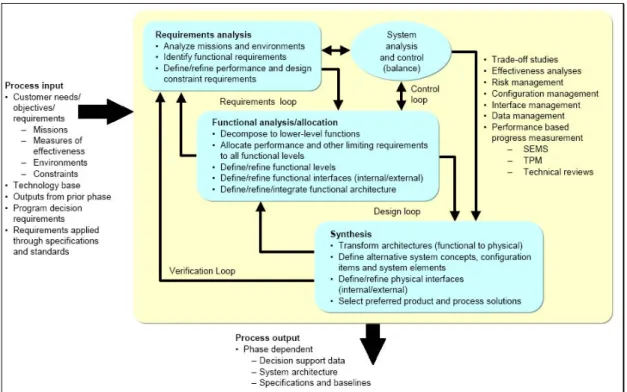
The fundamental system engineering activities are Requirements Analysis, Functional Analysis /Allocation, and design Synthesis. Systems engineering controls are used to track cost and schedule, track technical performance, verify requirements are met, and review/audit the progress. Figure 1 represent a flow diagram of a typical Systems engineering process.
The system engineering process is applied to each level of system development, one level at time, to produce these descriptions commonly called configuration baselines. This results in a series of baselines, one at each development level. This baseline became more detailed with each level.
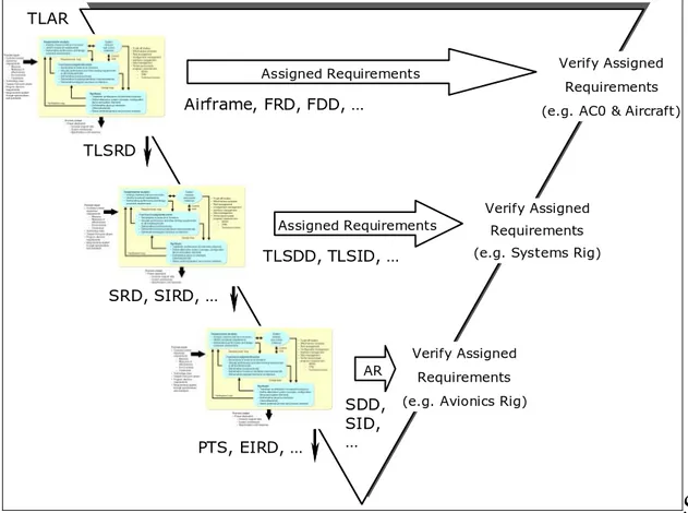
Figure 2 shows the systems engineering process applied to each level of the V-cycle.
The V-cycle is used to depict the systems engineering design process, where the left side of the V designates the design phase, and the right side the testing and implementation phase. TLAR Assigned Requirements Assigned Requirements AR TLSRD SRD, SIRD, … PTS, EIRD, … TLSDD, TLSID, … SDD, SID, … Verify Assigned Requirements (e.g. AC0 & Aircraft)
Verify Assigned Requirements (e.g. Systems Rig)
Verify Assigned Requirements (e.g. Avionics Rig) Airframe, FRD, FDD, … TLAR Assigned Requirements Assigned Requirements AR TLSRD SRD, SIRD, … PTS, EIRD, … TLSDD, TLSID, … SDD, SID, … Verify Assigned Requirements (e.g. AC0 & Aircraft)
Verify Assigned Requirements (e.g. Systems Rig)
Verify Assigned Requirements (e.g. Avionics Rig) Airframe, FRD, FDD, …
Figure 2 – The system engineering process applied to the V-cycle
During the system engineering process, architectures are generated to describe, understand and select the most appropriate system. The word “architecture” is used in various contexts, in the general field of engineering. It is used as a general description of how the subsystems join together to form the system. It can be also
a detailed description of an aspect of a system. In the system-engineering field this word is used to describe three different aspects:
• Functional Architecture: Identifies and structures the allocated functional and performance requirements.
• Physical Architecture: Depict the system product by showing how it is broken down into subsystem and components
• System Architecture: Identifies all the products (including enabling products) that are necessary to support the system and, by implication, the processes necessary for development, production, construction, deployment, operations, support, training and verification.
This work is a functional study that has been made from the aircraft level to the system level. It is an analysis on what the system is supposed to do, not on how the system will do it. A functional study is fundamental to create innovation. A framework, therefore has been created, not with the aim to solve the problems at the details level, but to give a wider, common view on the overall design process, to think about problems and their potential solution from a new point of view.
Operational Framework
In this thesis is shown how the building of a framework helps the design and the model and simulation activities for complex architecture such as a LG and its systems are. A framework, which contains all the requested information to specify the product, a framework to handle complexity and to provide the community of systems engineers assistance in building a coherent picture of the system. The Framework is a generic classification scheme for design artifacts, that is, descriptive representations of any complex object. The utility of such a classification scheme is to enable focused concentration on selected aspects of an object without losing a sense of the contextual, or holistic, perspective. In designing and building complex objects, there are simply too many details and relationships to consider simultaneously. However, at the same time, isolating
single variables and making design decisions out of context results in sub-optimization with all its attendant costs and dissipation of energy (waste from a lean perspective). Restoration of integrity or retrofitting the sub-optimized components of the resultant object, such that they might approximate the purpose for which the object was originally intended, may well be financially prohibitive. A balance between the holistic, contextual view and the pragmatic, implementation view can be facilitated by a Framework that has the characteristics of any good classification scheme, that is, it allows for abstractions intended to:
• Simplify for understanding and communication
• Clearly focus on independent variables for analytical purposes, but at the same time
• Maintain a disciplined awareness of contextual relationships that are significant to preserve the integrity of the object
It makes little difference whether the object is physical, like an aircraft, or conceptual, like an aircraft functions. The challenges are the same. How do you design and build it piece-by-piece such that it achieves its purpose without dissipating its value and raising its cost by optimizing the pieces, sub-optimizing the aircraft.
The framework is a comprehensive, logical structure for descriptive representations (i.e. models, or design artifacts) of any complex object and is neutral with regard to the processes or tools used for producing the descriptions. For this reason, the Framework, is helpful for sorting out very complex, technology and methodology choices and issues that are significant both to general management and to technology management.
Summarizing, the Framework is:
Simple: It is easy to understand ... not technical, purely logical. In its most elemental form, it has three perspectives: Owner, Designer, Builder ... and three
abstractions: Material, Function, Geometry. Anybody (technical or non-technical) should be able to understand it.
Comprehensive: It should address the aircraft in its entirety but allow focus in specific areas where details may be required. Any issues can be mapped against it to understand where they fit within the context of the Enterprise as a whole. a Language : It enable to think about complex concepts and communicate them precisely taking into account the different disciplines of the stakeholder.
a Planning Tool : It helps you make better choices as you are never making choices in a vacuum. You can position issues in the context of the Enterprise and see a total range of alternatives.
a Problem Solving Tool : It enables you to work with abstractions, to simplify, to isolate simple variables without losing sense of the complexity of the Enterprise as a whole.
Neutral : It is defined totally independently of engineering disciplines, tools or methodologies and therefore any tool or any methodology can be mapped against it to understand their implicit trade-offs, that is, what they are doing, and what they are not doing.
The Framework for aircraft architecture is just a tool, a tool for thinking and rationalizing. If it is employed with understanding, it should be of great benefit to technical and non-technical management alike, in dealing with the complexities and dynamics of aircraft during concepts, evaluation, marketing, design, prototyping, testing, production, development, operation, support, evolution and retirement.
Any Airbus Architectural Framework must bind operational context, an aircraft as a system, and all its constituent subsystems into a coherent and consistent definition that is not evidently incomplete.
A framework, to be defined and well understood by all the members of the community of systems engineers, must be specified using a System Definition Language a language that aids understanding and provides assistance in building coherent picture of a system construction.
SysML – System Modelling Language
The need of a unified language (as UML is for software engineer) capable of representing the many facets concerning systems design and complexity is the “Holy Grail” of System Engineering. As a possible answer Object Management Group (OMG) and International Council on System Engineers (INCOSE) have pushed towards the realization of SysML3 (System Modeling Language). It is “a
standard modelling language for system engineering to analyse, specify, design and verify complex systems. This language is intended to enhance system quality, improve the ability to exchange systems engineering information among tools, and help bridge the semantic gap between systems, software, and other engineering disciplines”4 quoting the definition given by the OMG.
In this study SysML is the “language” chosen to create one aspect of the framework, to model the architecture of interest.
In this thesis, the use of a system definition language, together with a simple framework, will try to answer the challenges placed at the beginning of the chapter.
This work is a process of reverse engineering, done using past programmes experiences, to show how this methodology is applicable, to show how to use SysML to represent the solution and what are the benefits that this approach could bring about. As soon as this methodology as been verified and validated, it could be deployed to ongoing programmes, as the framework is general and so maybe valid for every project.
Structure of the work
This study has been done as a part of MASP2, with application deployed to Common Virtual Bird (CVB) Pilot Project II – Aircraft on Ground Operations (A/C on GO).
This is an international project that involves the extended enterprise (i.e. all Airbus entities and suppliers) and which is aimed to improve A/C design with aid
3
See appendix
4
of Modelling and Simulation techniques. One of the objectives of the A/C on GO is to “extend the modelling and simulation of the Landing Gear System as an integral subsystem of the operational A/C during Taxi Out phase”.
For Airbus, the System of interest is the aircraft as an integrated whole. Airbus aircrafts operates in the World Air Transportation System, the containing System. The Landing Gear for example is a subsystem, which, in turn is composed of different subsystems.
Looking at the Landing Gear and its associated systems definition and design definition and design, the part to be taken into account are the structure and its interfaces. A complete view of the problem must take into account both the structure of Landing Gear, the airframe, the interacting systems and their integration. One of the major challenges facing Airbus’ engineers today is the smooth and timely integration and test of all the complex systems on the final Aircraft.
The work is divided in 3 main parts:
• Identification of all the requirements that could be useful for a correct development of the system. The requirements concerning the technical aspects come from the AP2161 Aircraft Function Definition Process. Some aspect have been taken from ATA32 A380 Top Level System Requirements Document (TLSRD).
The requirements referring to modelling and simulation activities come from the CVB scoping phase as requirements expressed by the interviewed stakeholders. The requirements, captured and handled in the first part of the work using the Quality Function Deployment (QFD) techniques, have been converted in customers’ needs and represent the guideline, which drive the entire project.
• Development of a Static Model. A static model is an ensemble of all information necessary to describe a system. It gives the system specification for dynamic model, containing all assumptions made, as
initial conditions, boundary conditions etc. Static model is not related with the tools used to implement a simulation of the system. It describes what the system is intended to do. The model is therefore the description of the system. The static model is synonymous wit a descriptive model.
• Deployment of the static model in the simulation environment, verification and validation of the model. All the information contained in the static model, used in a simulation environment, gives the dynamic model, in which all variables changing in time. The traceability between the descriptive model and the dynamic has taken into account. This is one of the most important and innovative outputs. The dynamic model is then an earlier representation of what a system will do.
Qualica QFD is the tool used to follow the QFD process. Artisan Studio 6.0 is the tool used to support the project in its definition (Static Model). In the simulation environment MSC.Adams 2005 integrated with Matlab-Simulink® has been used to run several simulation.
Conclusion
This work is aimed to give an example on an innovative concept of design. It shows how the use of a system definition language and the realisation of a framework can lead to a more structured approach to the design, from the early stages. The unified language reduces problems of communications and so potential misunderstanding. The framework guarantees a robust base for future development and changes, and enables the complexity of the architecture to be handled.
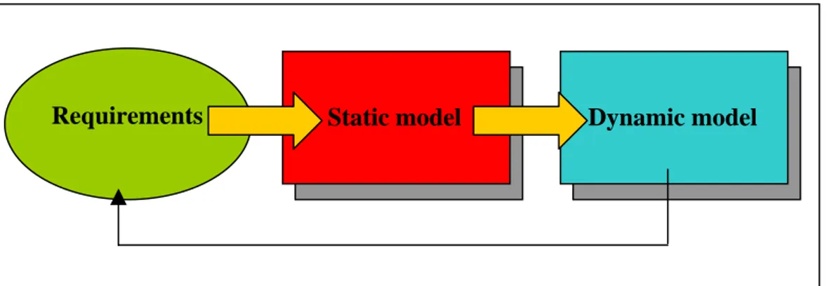
The framework is an invariant entity that can be used by all the programmes. Once the framework is in place the link between the requirements and the dynamic model is automatic. This aspect represents the major improvement achieved. If there is a change in the requirements, what changes is the flow of
information, which probably leads to a change in the final behaviour of the product.
Static model Dynamic model Requirements
Figure 3 – Thesis Work stream
The work is made using a top-down approach. The intention of the top-down approach is to have a full picture of interactions at every level. In the top-down approach all the interactions (for instance integration between systems) are taken into account. If a bottom-up approach was used instead, the full picture would have been missed and the problems would have been probably founded late in the project, with a foreseeable rise in terms of cost and time.
It is a new approach and design to describe the model looking at the physical and computational aspect at the same time. It is key to note that the description of model is synonymous with the description of the system.
This kind of formalization, has been made in this work at A/C level, but could reused, changing some boxes at each level down in the design cycle, that is to say for systems, subsystems, components.