Universit`
a degli Studi di Pisa
Facolt`a di Scienze Matematiche, Fisiche e Naturali
PhD Thesis in Applied Physics
April 2006
The control of the Virgo interferometer
for gravitational wave detection
Supervisors:
Prof. Francesco Fidecaro Dr. Matteo Barsuglia
Author:
...e ho scritto nemmeno la met`a di ci`o che ho visto. Marco Polo
Acknowledgments
My first idea was to use this space to thank one by one all the people who somehow helped me in my 3 years long journey. I realize only now that this would imply to write some other tens of pages, and the dimension of this thesis would become quite embarrassing. So, I need to change strategy.
To Francesco, the I.N.F.N Pisa group and the Virgo collaboration, thank you for believing in me and giving me the possibility to present our results to the interna-tional scientific community.
To Edwige and all the commissioning group, thanks for the time spent together in control room (e in particolare per le cene a base di pizza e cinque e cinque).
To Giovanni, thank you for all your useful suggestions. To Raffaele, thank you for always being around.
To Paolo, thank you for answering to all my daily questions.
To Adalberto, thank you for showing me the enthusiasm with which this work should be done.
To Maddalena, thanks for your encouragement and all the nice figures you did for me (and all the pictures you took when I was sleeping on my chair..).
To Gary and Matt, for your patience with my poor English. Thank you. To Matt, thank you also for all your Evans comments. And thank you more for showing me how many things can enter in a small zaino.
Al mio maestro, Stefano, thanks. I hope to have understood the message. At the end, al mio capo, Matteo. Per questa nostra mitica avventura insieme, grazie. Grazie di tutto.
Contents
1 Gravitational Waves and their Detection 13
1.1 Sources . . . 13 1.1.1 Supernovae . . . 15 1.1.2 Coalescent Binaries . . . 15 1.1.3 Neutron Stars . . . 16 1.1.4 Stochastic Background . . . 17 1.2 Interferometric detection . . . 17 1.2.1 Michelson interferometer . . . 18 1.2.2 Fabry-Perot cavities . . . 22
1.2.3 Recycling of the light . . . 23
1.2.4 Seismic noise . . . 24
1.2.5 Thermal noise . . . 25
2 The VIRGO Detector 27 2.1 Injection system . . . 30
2.1.1 The input mode-cleaner . . . 30
2.2 Detection system . . . 31
2.3 The Mirrors . . . 33
2.4 Mirror suspension system . . . 34
2.4.1 Main elements of the SA . . . 35
2.4.2 Inertial damping . . . 37
2.4.3 Local control . . . 38
2.4.4 Performance . . . 38
2.5 Control and Signal Readout . . . 40
2.5.1 Longitudinal control . . . 40
2.5.2 Frequency stabilization . . . 43
2.5.4 The control chain . . . 48
3 The Longitudinal Control 53 3.1 Specifications . . . 54
3.1.1 Common arm length and recycling cavity length . . . 55
3.1.2 Differential arm length and differential Michelson length . . 56
3.2 Single Fabry-Perot Cavity . . . 57
3.2.1 Pound-Drever-Hall locking . . . 57
3.2.2 Lock acquisition . . . 61
3.3 The Recombined ITF . . . 64
3.3.1 Operating Point . . . 65
3.3.2 Locking Scheme . . . 66
3.4 The Recycled ITF . . . 68
3.4.1 Locking signal readout . . . 71
3.4.2 Lock acquisition . . . 74
4 The Commissioning of Virgo 83 4.0.3 Commissioning evolution and commissioning runs . . . 86
4.0.4 The new suspended input bench . . . 87
4.1 Simulation of the Interferometer . . . 88
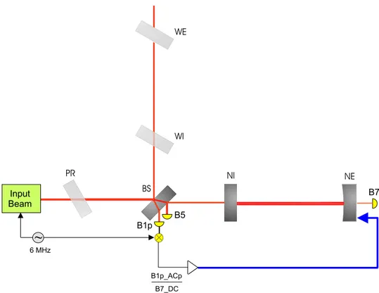
5 Control of the 3 km cavity 91 5.1 Experimental set-up . . . 91
5.2 Single Arm Locking Scheme . . . 94
5.3 Simulation . . . 95
5.3.1 Cavity length reconstruction . . . 96
5.3.2 Feedback to the mirror . . . 99
5.3.3 Locking efficiency . . . 100
5.4 Check of sub-system specifications . . . 101
5.5 Experimental performance . . . 106
5.6 Commissioning of the single arm . . . 108
5.6.1 Lock of the OMC . . . 108
5.6.2 Automatic alignment (AA) . . . 110
5.6.3 Frequency stabilization . . . 111
6 Control of the Fabry-Perot Michelson (recombined ) interferometer117
6.1 Lock acquisition strategy for the Recombined ITF . . . 118
6.1.1 Simulation . . . 118
6.1.2 The Anderson offset . . . 123
6.1.3 Simulation . . . 125
6.1.4 Generation Mechanism . . . 125
6.1.5 How to deal with the Anderson offset . . . 129
6.2 Linear Locking . . . 131
6.2.1 Controller . . . 132
6.3 Commissioning of the Recombined ITF . . . 133
6.3.1 Suspension hierarchical control . . . 134
6.4 Sensitivity and Noise Budget . . . 135
6.4.1 Commissioning run C4 . . . 136
6.4.2 Commissioning run C5 . . . 138
7 Lock Acquisition of the Recycled Interferometer 141 7.1 Simulation of the multi-step technique . . . 142
7.2 Use of the 3Ω signal . . . 143
7.3 Experimental tests of the multi-step technique - I . . . 146
7.3.1 Lock of the central ITF (CITF) . . . 147
7.3.2 Step3North and Step3West . . . 149
7.4 Absence of optical isolation between input mode-cleaner and interfer-ometer . . . 151
7.5 The control of the power recycling mirror . . . 154
7.6 Experimental tests of the multi-step technique - II . . . 156
7.7 Variable finesse locking technique . . . 157
7.7.1 Reconstruction of the lengths . . . 159
7.8 Feedback to the mirrors . . . 164
7.8.1 The control filters . . . 164
7.8.2 The driving matrix . . . 164
7.9 Misalignment of the PR mirror . . . 166
7.10 Moving to the dark fringe . . . 166
7.10.1 The dynamic sensing matrix . . . 168
7.11 The frequency stabilization servo . . . 169
7.12 Lock acquisition sequence . . . 171
8 Commissioning of the recycled ITF 177
8.1 Commissioning run C5 . . . 178
8.1.1 C5 noise budget . . . 179
8.2 Instabilities in the ITF power . . . 180
8.3 Interferometer automation . . . 183
8.4 Automatic alignment . . . 183
8.5 Reduction of the longitudinal control noise . . . 185
8.5.1 Use of more sensitive signals . . . 186
8.5.2 Optimization of the control filters . . . 189
8.5.3 Subtraction of the beam-splitter control noise . . . 190
8.5.4 Next steps . . . 192
8.6 Commissioning run C6 . . . 193
8.6.1 Duty-cycle and lock losses . . . 194
8.6.2 C6 noise budget . . . 195
8.7 Commissioning run C7 . . . 196
8.7.1 Noise hunting: next steps . . . 198
A Definition of Acronyms 203 B Fabry-Perot cavities 205 B.1 The reflected field . . . 207
B.2 Operating point . . . 208
C Pound-Drever-Hall signals in the recombined ITF 211 C.1 Asymmetric-Port signals . . . 211
Introduction
The General Theory of Relativity developed by Einstein in 1916 predicts the exis-tence of gravitational waves. These can be described as perturbations of the space-time metric propagating at the speed of light, produced by the acceleration of bodies. Because of the weakness of the intensity of a gravitational wave, only astrophysical sources are able to produce effects detectable on Earth. Since relative positions of free masses are determined by the the space-time metric, in principle it is possible to experimentally detect the passage of a gravitational wave by measuring the rela-tive distance variation induced in a set of suspended masses. However, the foreseen intensities of gravitational waves are so weak that length variations of the order of 10−18 m have to be measured. Because of the difficulties connected with such small
effects, no direct detection has been accomplished so far. Indirect proof of the exis-tence of gravitational waves was discovered by J.H.Taylor and R.A.Hulse in 1992 [1]. They measured energy losses in the orbit of the binary system PSR 1913+16, which turned out to be in agreement with results predicted by the gravitational waves emission.
The idea of using interferometry to detect gravitational waves started to be ex-plored a few decades ago [2], and in the last few years a number of ground-based laser interferometers have been put into operation: the three LIGO interferometers in the United States [3], the German-British GEO600 [4], the Japanese TAMA300 [5] and the Italian-French VIRGO [6].
VIRGO is a recycled Michelson interferometer (ITF) where each arm is replaced by a 3 km long Fabry-Perot cavity. It is located at the European Gravitational Observatory (EGO), close to Cascina (Pisa, Italy), and is designed to detect gravi-tational waves emitted by astrophysical sources. Mirrors are suspended in vacuum by high performance suspensions, so that detection is possibly starting from very low frequencies, a few Hz, up to a few kHz. The main subsystems of VIRGO were tested in 2001-2002, during the commissioning of the Central Interferometer, a 6m-long
recycled Michelson interferometer [52]. In September 2003, following completion of the installation of the 3km arms, VIRGO commissioning began, with the goal of putting into operation the detector and reaching the designed sensitivity in a few years.
The work presented in this thesis is focused on the longitudinal control of VIRGO, that is the control of the position of the test masses along the light beam direction. Relative displacements of the mirrors need to be actively controlled in order to bring and keep the interferometer on its working point. By following the evolution of the VIRGO commissioning, suitable strategies have been designed and applied to differ-ent optical configurations: a single Fabry-Perot cavity, a Michelson interferometer with Fabry-Perot cavities in the arms (the recombined ITF), and finally the full interferometer (the recycled ITF). Once the lock of full VIRGO was achieved, the process of investigating and reducing the longitudinal control noises coupled into the dark fringe signal began.
Chapter 1 describes possible sources of gravitational waves, and principles of their interferometric detection. VIRGO is presented in Chapter 2, where the main characteristics of the sub-systems composing the detector are shown. In Chapter 3 the main aspects of longitudinal control of the ITF are introduced, together with techniques currently adopted by detectors with an optical configuration similar to VIRGO, such as LIGO and TAMA. The organization of the commissioning of Virgo is summarized in Chapters 4. Chapters 5 and 6 describe the design and imple-mentation of the longitudinal control in simpler optical configurations: the single Fabry-Perot cavity and the recombined ITF.
The longitudinal control of VIRGO in its final recycled configuration, achieved by means of an original technique called variable finesse locking, is detailed in Chapter 7. Development and application of this technique represents the primary original contribution of the author to the Virgo commissioning effort. The concept behind the technique is new to the community and broadly applicable to existing and future gravitational wave detectors.
Performance of the VIRGO interferometer and progress in its sensitivity are finally shown in Chapter 8 on the basis of the data collected in three commissioning runs, the last one performed in September 2005.
Chapter 1
Gravitational Waves and their
Detection
This first chapter briefly presents the expected gravitational waves sources and the principle of interferometric detection with a simple Michelson ITF. The optical con-figuration adopted in Virgo, a power recycled Michelson ITF with Fabry-Perot cav-ities in the arms, allows the interferometer sensitivity to be increased.
The three fundamental noises limiting the present interferometric detectors sen-sitivity are seismic noise, thermal noise and shot noise. In particular, their con-tributions to the Virgo design sensitivity, better described in the next chapter, are introduced here.
1.1
Sources
Gravitational waves are produced by the acceleration of bodies. The conservation of mass-energy, linear momentum, and angular momentum makes null the gravitational wave emission associated with monopole, dipole, and magnetic dipole radiation, respectively. The first contribution different from zero is given by the quadrupole moment, producing an oscillating strain transverse to the propagation direction:
hjk = 2G rc4 · d2Q jk dt2 ¸ t−r/c (1.1)
where r is the distance between the source and the observer and Qjk is the reduced quadrupole term associated with the mass distribution ρ(−→x ):
Qjk = Z ρ(−→x ) · xjxk− 13δij|−→x |2 ¸ d|−→x |
The quadrupole moment of a body of mass M and characteristic radius R can be estimated as:
Q ∼ M R2 (1.2)
The order of magnitude of the strain amplitude of the gravitational wave is therefore: h ∼ 1 r G c4 M R2 T2 (1.3)
where T is the typical time of variation of the mass distribution. In terms of the typical speed of displacement v = R/T , h can be written as:
h ∼ 1 r GM c2 ³ v c ´2 (1.4) The designed sensitivity of detectors such as LIGO and VIRGO is of the order of 10−22at 100 Hz. Since G/c2 is a very small quantity1, only astrophysical massive
bodies can be detected on Earth.
On the base of the time evolution of the emitted signals, gravitational waves sources can be classified as:
• impulsive sources (bursts), such as supernovae explosions or coalescent binary systems at their merging phase;
• quasi-periodic sources, such as coalescent binary systems; • periodic sources, such as spinning neutron stars;
• stochastic background from either astrophysical or cosmologic origin. In the following sections, detection rates of gravitational waves for first generation interferometers, operative in the short term (2006-2007), are described.
1 G
c2 ∼ 10−29 m 3
1.1.1 Supernovae
The gravitational wave signal associated with a supernova explosion typically lasts a few ms, and thus exhibits a broadband high-frequency spectrum, extending to a few Hz. The amplitude of the emitted pulse is modeled as:
h ∼ 2.7 × 10⁻²⁰ µ ∆E M¯c2 ¶1/2µ 1 kHz f ¶1/2µ 10 Mpc r ¶ (1.5) where f is the inverse of the collapse time and ∆E is the energy emitted in the form of a gravitational wave, depending both on the collapse speed and its degree of asymmetry.
Advanced astrophysical simulations predict an emitted energy ∆E/M¯c2 ∼
10−6 [8]. This scarce value makes the amplitude too low to detect a supernova in the
nearest galaxy cluster (Virgo), where several events per months are expected [7]. In our galaxy the expectation is reduced to only a few events per century, so that the first generation of interferometers are not supposed to detect more than one event every several years.
1.1.2 Coalescent Binaries
Gravitational waves are emitted by binary systems composed of compact objects: a couple of neutron stars (NS), a couple of black holes (BH), or one NS and one BH. Energy is progressively lost through gravitational radiation. The orbital radius is reduced accordingly, so that the emission frequency increases until the coalescence of the two bodies (corresponding to a frequency of about 1 kHz for NS-NS2. Binary
systems can only be detected by ground-based interferometers in the last minutes of their life, when the emission frequency is higher than several Hz. The rate of available signals is therefore low, despite the large number of compact binary systems in the close universe.
The horizon is defined as the maximum distance to which an optimally positioned and oriented binary can be detected3 with a minimum signal-over-noise ratio (SNR)
of 8. The estimates of the event rate are affected by large uncertainties [10], as reported in table 1.1:
2The NS mass is known to be around 1.4 MJ. For the BH mass, 10 MJ will be used in the
following pages.
3The effective range of the interferometer is also averaged over all sky positions and binary
orientations, and is called the inspiral range. According to this definition, the inspiral range has to be multiplied by a factor ∼√5 to obtain the horizon.)
1st generation interferometers Horizon Rates (min - max) NS-NS 30 Mpc 0.0003/yr − 0.3/yr NS-BH 40 Mpc 0.0004/yr − 0.5/yr BH-BH 145 Mpc 0.001/yr − 3/yr
Table 1.1: Horizon and detection rates for coalescing binary sources.
Recent studies [11] suggest that short-hard gamma rays bursts result from a long-lived progenitor system, such as NS-NS or NS-BH binary systems. According to this model, the predicted rate of such signals, detectable by first generation interferometers, increases from one every few years to several events per year. One of the most relevant aspects in the detection of compact objects inspiral signals is that their waveforms are considered to be known well enough to be detected by a matching filter technique.
1.1.3 Neutron Stars
Spinning neutron stars with asymmetry around the rotation axis emit gravitational waves mainly at twice their rotation frequency. About 109 spinning neutron stars
are present in our galaxy, with rotation frequencies of between fractions of Hz and a few hundred Hz [9]. However, only a few percent neutron stars emit at a frequency f within the detection band of ground-based interferometers, above the tens of Hz. The amplitude strength of the emitted signal is:
h ∼ 10−21² µ f 100 Hz ¶2µ 10 kpc r ¶ (1.6) where ² is the asymmetry of the mass distribution. The SNR for a signal emitted at a fixed frequency is proportional to the square root of the integration time, so that it can be increased by means of a long observation time. The problem is that the Doppler effect due to the Earth motion has to be subtracted independently for every direction of the sky, requiring very large calculation times.
Upper limits for ² can be given by attributing the entire spin-down of the pulsar to the gravitational wave emission. For the Crab pulsar, spinning at 30 Hz, this is 7 × 10⁻⁴, corresponding to a maximum possible amplitude around 10−24for a
gravi-tational wave signal emitted at 60 Hz. Under this hypothesis, such a signal could be detected in one year by first generation interferometric ground-based detectors [12].
1.1.4 Stochastic Background
Gravitational waves are also present in the Universe as a stochastic background. They are formed by a superposition of random signals coming from all directions at all frequencies, produced by both cosmological and astrophysical sources.
The proposed detection scheme generally involves correlation techniques between different detectors. As shown in [13], the stochastic background floor is presently estimated to be well below the sensitivity of even the more advanced detectors, so that this gravitational wave source can be sensibly neglected for first generation interferometers.
As shown in the previous sections, the rate estimates are very uncertain and largely depend on the applied model. It is therefore very difficult to evaluate the effective possibility of detecting gravitational waves with the current interferometric detectors.
The most promising sources are presently considered to be coalescent binaries, with several events per year according to recent encouraging studies. Moreover, the evolution of the signals can be well modeled, so that a matching filter technique can be applied.
1.2
Interferometric detection
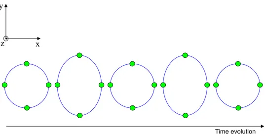
A gravitational wave detector has to convert the effects produced by a gravitational wave passage into a measurable signal. The base of the interferometric detection of all the large-scale instruments is a Michelson ITF with suspended mirrors [14], illuminated by a monochromatic laser source. Above the frequency of the pendulum resonance, suspended mirrors behave as free masses, therefore forming a free falling reference system. The passage of a gravitational wave induces a change in the relative distance of the mirrors (see figure 1.1). A consequent variation occurs in the power transmitted at the anti-symmetric (ASY) port, detected by means of a photo-detector (see figure 1.2).
Different variants of this scheme are currently adopted by the interferometric detectors all over the world.
Virgo, in particular, is a power-recycling Michelson interferometer with Fabry-Perot cavities in the arms. The reasons for this choice are briefly summarized here.
Figure 1.1: Effect of a gravitational wave propagating along the z direction on free falling test masses placed in a ring.
1.2.1 Michelson interferometer
The Michelson ITF optical configuration is shown in figure 1.3. A beam splitter mirror (BS) is impinged upon by a laser source. Half of the light is transmitted along the laser propagation direction, the other half is reflected into the perpendicular axis. The two beams are reflected from the input (IM1) and end (IM2) mirrors and
recombined at the BS.
The passage of a gravitational wave with amplitude strain h and optimal orien-tation and polarization produces a differential change ∆lGW in the length of the two
Michelson arms, which is given by:
∆lGW = l0h (1.7)
where l0 is the average of two unperturbed arm lengths. ∆lGW is measured by
means of the differential phase shift ∆φGW induced in the light returning to the BS:
∆φGW =
4π
λ hl0 (1.8)
where λ is the wavelength of the laser light.
The wave passage can be detected by a photo-detector placed at the ASY port. Given a power Pinimpinging on the BS, the power detected by the photo-detector
Figure 1.2: Base of the interferometric detection: a Michelson ITF with suspended mirrors, illuminated by a monochromatic laser source. The beam transmitted to the anti-symmetric port is measured by a photo-detector.
Pasy = rBStBS[r12+ r22+ 2r1r2cos(2k∆l)]Pin (1.9)
where r1and r2 are the amplitude reflectivity of the end mirrors, rBS = tBS =
√ 2/2 are the reflectivity and the transmissivity of the BS and δl = l1− l2 is the length asymmetry between the two arms. By introducing the contrast defect C, defined as
C = P
max
asy − Pasymin
Pmax
asy + Pasymin
= 2r1r2 r2 1+ r22 (1.10) equation 1.9 becomes: Pasy = Pin 2 [1 + Ccos(2k∆l)] (1.11)
The length asymmetry ∆l between the two arms is composed of a static difference ∆l12 plus the perturbation due to the passage of the gravitational wave δlGW. By
considering the corresponding phase shift and keeping the first order terms, the previous expression can be written as:
Pasy = Pin
Figure 1.3: Michelson ITF optical configuration.
The variation produced by the wave passage is therefore:
δPGW = −P2inCsin(∆φ12)δφGW (1.13)
In order to get the maximum sensitivity of the detector, ∆φ12 has to be optimized considering the limitation imposed by the shot-noise on the minimum detectable phase. The number of photons N with frequency ω/2π impinging upon the photo-diode having efficiency η in the interval time δt is given by:
N = ηPasy∆t
¯hP lanckω (1.14)
Because of the Poissonian statistics associated with this process, δNshot ∼
√ N , so that the corresponding variation induced in the power is:
δPshot= s
Pasy¯hP lanckω
η∆t (1.15)
The optimal value of ∆φ12 can be found by maximizing the signal to noise ratio:
S N =
|δPGW|
The dark fringe condition of the instrument, that is null power going out of the ITF at the ASY port, corresponds to:
cos∆φ12≈ −1, with C ∼ 1 (1.17) The minimum value of the detectable phase is found by imposing S/N = 1. Its corresponding linear spectral density is:
˜
δφminGW = s
¯hP lanckω
ηPin (1.18)
and, in terms of the amplitude strain linear spectral density of the gravitational wave: ˜hmin= 1 2π(l1+ l2) s hP lanckcλ Pinη /√Hz (1.19)
By considering the nominal Virgo parameters (λ = 1.064 µm, η ≈ 0.78 and incoming power P = 20 Watt), and by assuming 3 km long Michelson arms (l1∼ l2 ∼ 3 km):
˜hmin ∼ 2 · 10−21 /√Hz (1.20)
The linear spectral density of a typical gravitational wave signal with amplitude h = hRM S ∼ 10−22 in a frequency band ∆f ∼ 100 Hz is instead:
˜hGW ∼ 10−23 /√Hz (1.21)
which is a few orders of magnitude less.
According to the previous equation, in order to further improve the sensitivity, longer arms and more powerful lasers should be used. However, arms longer than a few kilometers are not feasible, and more powerful lasers do not satisfy the required frequency stability. The alternatives adopted by Virgo and other detectors consist of amplifying the phase shift accumulated in the arms by means of Fabry-Perot cavities, and increasing the power inside the ITF by using the technique of power-recycling.
Figure 1.4: Optical configuration consisting of Michelson ITF with Fabry-Perot cavities in the arms.
1.2.2 Fabry-Perot cavities
In order to amplify the optical path of the light inside the ITF, Fabry-Perot cavities are inserted in the arms (see figure 1.4).
The response of a Fabry Perot cavity is detailed in appendix B. Its remarkable property is that when the cavity is at resonance the phase shift induced by the grav-itational wave’s passage is increased, with respect to the single mirror configuration, proportionally to the finesse F of the cavity. The amplification given by the cavity is valid only if the period of the gravitational wave is longer than the storage time of the light inside the cavity itself.
The shot-noise limited sensitivity of a Michelson with Fabry-Perot cavities in the arms is: ˜hshot(f ) = 1 4(L1+ L2)F s 2hP lanck λc ηPin s 1 + µ f fF P ¶2 /√Hz (1.22) where L1 and L2 are the lengths of the two cavities and fF P = c/4LF is the
Fabry-Perot cut-off frequency.
Figure 1.5: Optical configuration consisting of a power recycling Michelson ITF with Fabry-Perot cavities in the arms.
1.2.3 Recycling of the light
In order to increase the power impinging on the BS, the technique of light recycling is applied [15] [16]. As shown before, the dark fringe condition is required to optimize the interferometer response. This implies that, by assuming low light losses and a good contrast of the ITF, a large part of the light is reflected back from the ITF to the laser source. By appropriately placing a power recycling mirror (PR) in between the BS and the laser source (see figure 1.5), the light reflected from the ITF can be made resonant with the incoming one. The maximum recycling gain Grec of the
circulating power depends on the total losses of the ITF Ltot:
Grec ≈ 1 Ltot
and it can therefore be increased by reducing, as much as possible, the losses of the ITF. For Virgo, the nominal recycling gain is Grec ≈ 50 [17]. The resulting
configuration is therefore a power recycling Michelson ITF with Fabry-Perot cavities in the arms.
improves by a factor 1/√Gric: ˜hshot(f ) = 4(L 1 1+ L2)F s 2hP lanckηGλc ricPin s 1 + µ f fF P ¶2 /√Hz (1.23) According to the Virgo parameters, the linear spectral density of the shot noise is of the order of 10−23/√Hz, two orders of magnitude less than would be obtained
in simple Michelson configuration. The shot noise limits the Virgo sensitivity at high frequency, starting from 500-600 Hz.
The other limiting fundamental noise sources in the low and mid frequency region for this kind of detector are seismic noise and thermal noise. These are described in the next paragraphs.
1.2.4 Seismic noise
The seismic noise transferred from the ground to the mirrors is the low frequency limiting noise source for interferometric detection. The amplitude and spectrum of the seismic noise of the ground where the ITF is located are strongly dependent on its geologic conformation and on human activities, but is always several orders of magnitudes higher than the required sensitivity. For instance, on the Virgo site, the contribution of the seismic noise at f ≥ 0.5 Hz is:
˜hsism(f ) ∼ 10−9 µ 1 Hz f ¶2 /√Hz
Therefore, without a high performance mirror suspension system, detection would not be possible.
The simplest system is to suspend the mirrors of the ITF to pendulums. Above its resonance frequency f0, a simple pendulum is actually a second order low pass
filter, so that the pendulum displacement x(f ) is depressed with respect to the displacement of the pendulum suspension point xsusp(f ). In terms of their linear
spectral density, it can be written as: e x(f ) e xsusp(f ) = −f02 f2 (1.24)
On the basis of this principle, different solutions are currently adopted by ground-based interferometric detectors. As described in the next chapter, Virgo uses the Superattenuators, high performance multi-pendulum stages. The detection is there-fore enabled down to 4 Hz. At that frequency the newtonian noise, induced by local gravity field fluctuations, is a limiting noise source as well.
1.2.5 Thermal noise
Thermal noise is another fundamental noise source limiting interferometric detec-tion. A system in thermal equilibrium with the environment is affected by state fluctuations, connected with dissipation phenomena. In the mechanical system con-stituted by the mirror suspension, internal dissipation is present both in the mirror substrates and in the suspension wires.
The suspended mirror can be assimilated to a simple pendulum of mass m, having a resonant angular frequency ω0 immersed in a thermal background at the
temperature T . In the hypothesis of dissipation due to the material structure, the equation of the pendulum motion can be modeled in the frequency domain by including an imaginary part φ(ω) in the Hook law [19]:
¨
x(ω) + ω02[1 + iφ(ω)]x(ω) = F/m (1.25) Experimentally, φ(ω) ∼ 10−6.
The system dynamics and the frequency spectrum of the thermal noise can be connected by means of the fluctuation and dissipation theorem [18]:
S˙x = 2kBT Re(Y (ω)) (1.26)
where Y (ω) = ˙x/F . For a low loss oscillator, Q = φ−1(ω
0), so that the thermal
noise spectrum of the oscillator can b written as:
˜ xterm(ω) = v u u t4kBT ω02 mQω 1 ¡ ω2− ω2 0 ¢2 + ω40 Q2
The frequency dependence of the thermal noise is therefore: • ∝ ω−1/2, when ω << ω0;
• ∝ ω−5/2, when ω >> ω 0
The limit in detector sensitivity due to thermal noise is mainly dependent on the structure of the adopted suspension mirror. In Virgo pendulum movements have very high Q (∼ 106) resonant frequencies below 10 Hz. The transverse violins
modes are present starting from a few hundreds of Hz, the vertical ones are around a few tens of Hz, with Q ∼ 105. Internal vibrational modes of the mirrors are of the
noise limits the Virgo sensitivity curve from 4 Hz to 500 Hz.
Not fundamental but technical noises, mainly connected with the control of the instrument, are the limiting sources of noise in the preliminary commissioning phase of any interferometric detector. Some of the noises presently limiting the Virgo sensitivity curve will be described in the next chapters. All of these noises are supposed to be reduced below the required level by the end of the commissioning phase.
Chapter 2
The VIRGO Detector
Virgo is located in the plain of Cascina, near Pisa (see figure 2.1).
Figure 2.1: The Virgo site.
All of the large optics are suspended in an ultra-high vacuum system by the so-called superattenuators, multipendulum isolators able to greatly reduce seismic noise at a very low frequency, thus enabling a high sensitivity down to a few Hz.
Figure 2.2: Virgo optical scheme.
by a laser Nd:Yag (λ = 1064 nm) with a power of 20 Watt. It is stabilized in frequency and position both by active controls and by passive filtering through a suspended triangular cavity, the input mode-cleaner (IMC). Mainly because of IMC internal losses, only half of the incoming power enters the interferometer, through the power-recycling mirror (PR). The beam is then split by the beam-splitter mirror (BS) into two beams which enter the two long Fabry-Perot cavities, to be then reflected to the BS, where they are recombined. Together with the Fabry-Perot Michelson ITF, the PR forms another Fabry-Perot cavity of about 12 m, the power recycling cavity, having a designed gain of 50. The power upon the BS is therefore 500 Watts.
The light passes many times through the optical substrates, so these need to be extremely pure, with low diffusion and low absorption. Mirror coatings also need to fulfill constraints on the wavefront surface deformation of less than λ/100. Total losses are around tens of ppm.
In order to improve the contrast, a suspended output mode-cleaner (OMC) fil-ters the interferometer out-going main beam, which is then focalized onto InGaAs
photodiodes.
Figure 2.3: Virgo design sensitivity (See also the official Virgo Sensitivity curve repository http://www.virgo.infn.it/senscurve).
The noises limiting the Virgo design sensitivity, already described in the previous chapter, are:
• seismic noise, up to 4 Hz. The high superattenuator performance, guarantees a reduction by a factor of 1015 at 10 Hz of the seismic noise transferred to the
mirrors, enabling detection down to a very low frequency;
• thermal noise, dominating the sensitivity in the intermediate frequency region, with the pendulum thermal noise up to 30 Hz and the mirror thermal noise from 30 Hz to about 500 Hz;
• the shot noise, together with the low pass filter of the Fabry-Perot cavities above 500 Hz.
e h ' 3 × 10⁻²¹ √1 Hz @ 10 Hz (2.1) e h ' 7 × 10⁻²³ √1 Hz @ 100 Hz (2.2)
2.1
Injection system
The injection system is the ensemble of components needed to produce the laser beam entering the ITF, to pre-stabilize it and to spatially adapt it to the ITF. The laser beam (20 Watts at λ =1064nm) is produced by a slave N d : Y V O4 high power
laser injection-locked to a 1 Watts N d : Y AG master laser. The laser is located on a bench rigidly connected to the ground, in air. It is found in the laser laboratory, a room separated from the experimental main area. The laser light is modulated in phase at the frequencies of 6.26 MHz and 22 MHz (see sections 2.5.2 and 3.4.1) before passing through the suspended injection bench, placed in vacuum.
The following main components are located on the suspended external bench (see figure 2.4):
• the input and output plane mirrors, which compose the input mode-cleaner; • two mirrors (M5 and M6) of a three mirror spherical telescope, which adapts
the beam coming out the mode-cleaner (having a waist of 5 mm) to the ITF (waist w0 = 2 cm on the input mirrors). The last mirror of the telescope is
the power recycling mirror;
• a 30 cm ultra-stable monolithic triangular cavity (RFC), used as reference for frequency pre-stabilization.
Together with the two mirrors located on the bench, a third suspended curved mirror at a distance of 144 m composes the IMC.
2.1.1 The input mode-cleaner
The main goal of the IMC is to filter the fluctuations of the laser beam position (beam jitter ). The filtering properties of a suspended cavity can be explained in the following way. The fundamental mode of a misaligned laser beam is seen in the optical axis of a cavity as a linear combination of higher order modes in the base of the cavity itself. In the same way, any input jittering beam is seen by the cavity
Figure 2.4: Schematic view of the injection system.
as composed of a linear combination of transverse modes. Since only the T EM00
mode is kept resonant and since the cavity is suspended, the IMC out-going beam is stable in position.
The Virgo IMC is a triangular Fabry-Perot cavity 144 m long, with finesse F ∼ 1000. The amplitude of the higher order modes entering the ITF is reduced by a factor 103, reducing by the same amount the phase noise induced by the beam jitter.
Moreover, as in all the Fabry-Perot cavities, the IMC is a first order low-pass filter for power and frequency fluctuations of the laser, with a cut-off frequency equal to its cavity pole (f0 = 4LFc ∼ 500Hz).
2.2
Detection system
The detection system is composed of two parts: the suspended detection bench, placed in vacuum, and the external detection bench, not suspended and in air. The
suspended detection bench mainly holds the output telescope and the output mode cleaner (OMC), a monolithic optical cavity 2.5 cm long of finesse F = 50, which filters higher order modes of the beam, transmitting only the fundamental one. The main beam leaves the suspended bench to reach the external bench, where a set of InGaAS photodiodes (B1) are located in order to detect the signal. About 1% of the beam coming out of the anti-symmetric port is directly detected by a different photodiode (B1p), still located on the external bench, without passing through the OMC. The read-out scheme of the signals demodulated at the modulation frequency (Ω-demodulated signals, see section 3.4.1) is done as shown in figure 2.6.
Figure 2.5: Scheme of the detection bench.
The signal produced by each photodiode first goes through a tuned preamplifier, attached to the photodiode, in order to amplify the Ω-component with respect to
Figure 2.6: Read-out scheme of the signal demodulated at the modulation frequency.
the harmonics. Then, the RF signal coming from the preamplifier is split into two signals, both of which are transferred to the demodulation board 2.7. Each of these is passed through a mixer, using, as a second input signal, a Ω-modulated reference signal provided by the Local Oscillator board (LO). One of the two LO signals is de-phased by 90◦ before entering the mixer, in order to produce, as output, the two
signals, demodulated at 0◦ (in-phase, P ) and at 90◦ (quadrature-phase, Q).
Figure 2.7: Schematic view of the demodulation board for one channel (P). After the mixer, the signal is passed through a compression filter, which increases the gain above 10 Hz by a factor of 35. After an anti-aliasing filter, the signal is sampled at 20 kHz by a 16 bit ADC.
2.3
The Mirrors
The input and end mirrors of the ITF are fused silica cylinders, with a diameter of 35 cm and mass of 20 kg. The BS mirror is smaller, with a diameter of 23 cm and mass of 5 kg. The PR mirror has a mass of 20 kg, but presents a composite structure that is different with respect to all the other mirrors, as will be better described in chapter 6.
The main parameters of the mirrors: the radius of curvature (ROC), the reflec-tivity (R) and transmissivity (T), the losses of the high reflecreflec-tivity (HR) and anti reflectivity (AR) coatings, are reported in the following tables.
Shape 1stface Shape 2ndface R 1stface T 2ndface Losses HR Losses AR
NI Flat Flat 132 ± 2 ppm 11.8 ± 0.03% 9.25 ppm 0.9 ppm
WI Flat Flat 171 ± 0.6 ppm 11.66 ± 0.02% 15.38 ppm 1.7 ppm
Table 2.1: Input mirror parameters
Shape 1stface Shape 2stface T 2stface Losses HR
NE Concave - ROC=3580 ± 17 m Flat 42.9 ± 0.02 ppm 4.67 ppm WE Concave - ROC=3601 ± 15 m Flat 38.3 ± 0.7 ppm 9.19 ppm
Table 2.2: End mirror parameters
Shape 1stface Shape 2ndface R 1stface R 2ndface Losses HR Losses AR
BS Flat Flat 50.25 ± 0.18% 519 ± 10 ppm 6.85 ppm ppm
Table 2.3: BS mirror parameters
Shape 1stface Shape 2ndface R 1stface T 2ndface
PR Convex - 4.3 ± 0.04 m Flat 135 ± 2 ppm 7.3 ± 0.03 %
Table 2.4: PR mirror parameters
2.4
Mirror suspension system
The Virgo main optics are suspended in vacuum to multi-stages pendulums, the superattenuators (SA). The SA has been designed in order to greatly suppress the seismic noise transmitted to the mirror, with an attenuation factor of ten orders of magnitude starting at 4 Hz. Attenuation is needed not only for the horizontal displacement along the laser beam direction, but also, because of couplings between the different degrees of freedom, for the vertical displacement and the rotation of the pendulum chain around the vertical axis. The seismic attenuation is based on the following principles:
• the horizontal displacement of the suspension point of a pendulum is reduced by (f0/f )2, at a frequency f above the frequency f0 of the pendulum normal
mode. With a n-stages pendulum it is possible to obtain a total attenuation factor proportional to 1/f2n, at frequencies above the highest resonance of the
chain.
springs that allow oscillation in the vertical direction;
• the rotational mode frequencies are confined below a few Hz by locating the mass in structures that have a high momentum of inertia. Moreover, a con-nection of two consecutive stages by suspension wire with small diameter and located close to their centers of mass makes it possible to reduce the frequency rotational modes.
2.4.1 Main elements of the SA
The main elements of the SA are (see figure 2.8):
The inverted pendulum The suspension point of the multi-stage pendulum is attached on the top of an inverted pendulum (IP), a 6 m structure constituted by three aluminium legs connected at the bottom by a flexible joint, supporting a metallic ring on its top. It acts as a second order low-pass filter above its resonance frequency, forming a ”pre-isolator” for the seismic noise reaching the chain.
By modeling it as a massless vertical bar of length l, connected to the ground by an elastic joint with linear stiffness k and having a mass m at its top, the resonant frequency f0 can be written as:
f0 = 1 2π r k m − g l (2.3)
For Virgo, by suitably tuning these parameters, f0 ∼ 30 mHz.
The seismic filters A sequence of five mechanical filters replace the pendulum masses in the chain. Each mechanical filter is a rigid drum-shaped metallic structure with a total mass of about 100 kg. Each stage is connected to the following one through blade springs. Their stiffness is such that in the vertical direction the natural resonant frequency of the filter is about 1.5 Hz. The highest mode of the chain would be therefore fixed to 7.5 Hz, well above the designed detection frequency threshold of 4 Hz. A system of magnetic anti-springs has been developed to reduce the vertical stiffness of the blades and to confine the main vertical resonant frequency of each filter below the pendulum one [25].
The last stage The last stage of the SA consists of an element with four wings, called ”marionette”, from which four wires originate, supporting a reference mass and a mirror, as shown in figure 2.9. Displacement of the mirrors along the beam directions are controlled by means of four coils placed on the reference mass, acting on magnets glued to the back of the mirror. This guarantees that the reference mass recoils against the mirror, so that the center of mass of the reference mass-mirror system is at rest. The pendulum length of the last stage is about 0.7 m, corresponding at a resonance frequency along the beam direction of 0.6 Hz.
Figure 2.9: Last stage of the SA, formed by the marionette, the reference mass, and the mirror.
2.4.2 Inertial damping
The SA provides very good seismic isolation in the detection frequency band, above 4 Hz. However, at very low frequency, seismic noise is integrally transferred to the mirrors or even amplified by the 90 normal modes of the chain. An active control of the SA is therefore needed in order to reduce the residual motion of the suspended mirrors.
The basic idea of the inertial damping is to control the position of the suspen-sion point using inertial sensors (accelerometers) to produce suitable error signals. However, accelerometers are sensitive to the acceleration of the pendulum, but not to the motion of the pendulum at constant velocity. For this reason such a kind of control would be unstable with respect to drifts. Position sensors based on Lin-ear Voltage Differential Transformers (LVDT) are therefore used as well to extract suitable signals in order to extend the control bandwidth down to DC. LVDT are however referred to ground and may cause seismic noise injected in the feedback loop.
LVDT and accelerometers are mounted on the top stage of the SA in a trian-gular configuration. They produce signals sensitive to movements of the inverted
pendulum in all its three normal modes: two horizontal translations and the rotation around the vertical axis. These signals are appropriately combined, filtered and sent to pairs of coil-magnet actuators, able to move the inverted pendulum. Thanks to its very low stiffness, the inverted pendulum can be moved by applying very small forces. With a control bandwidth of 4 Hz, the seismic noise transferred to the mirror is reduced so as to produce displacement along the beam direction limited to a few microns.
2.4.3 Local control
The inertial damping previously described is not able to control some internal modes of the suspension involving the mirror. Moreover, a way to perform the alignment of the mirrors in DC is needed. A dedicated control system of the last stage of the superattenuator was therefore designed, in order to damp the angular and longitu-dinal modes involving the mirror and to be able to set and recover the reference angular position of each mirror. This local control system is referred to the ground. Longitudinal and angular local positions of the mirror are reconstructed measur-ing the position of a laser diode beam reflected by the mirror surface which works as an optical lever. A position sensing device (PSD) fixed to the tower is used (see figure 5.13). The marionette positions are measured through an additional optical lever reflected by a mirror attached to the bottom of the marionette. Four magnets are attached to the marionette and four coils are placed in front of them, at the level of the Filter 7. A similar system is made by four coils located on the reference mass, acting on four magnets glued to the back of the mirror. This guarantees the control of the mirror along the laser beam direction (z-axis), together with the control of rotations around the vertical axis (yaw ) and around the axis perpendicular to the beam (pitch). A further reduction of longitudinal and angular motion of the mirror has been measured, below respectively, 1 micron and 1 microrad.
The local control system can not be used when the ITF is in its working condition because it uses ground as a reference. However, it plays a crucial role in damping the mirror oscillations in order to permit the engagement of longitudinal and angular global control systems.
2.4.4 Performance
The measurement of the SA seismic isolation was done with the the Central Interfer-ometer (CITF) commissioned in 2001-2002. The CITF a power recycled Michelson ITF with 6 m long arms, which differs with respect to the final configuration for
Figure 2.10: Readout of mirror and marionette positions in the local control scheme.
the absence of the 3 km Fabry-Perot cavities, replaced by high reflectivity mirrors. The mirrors were suspended from the same SA as in Virgo. The CITF was kept locked on the dark fringe, so that any deviation from the destructive interference was compensated for by a feedback loop acting on one of the end mirrors. In this way, it could be used as a very sensitive instrument to measure the residual motion of the mirrors, in order to study the vibration isolation performance of the Virgo SA [25].
The measurement was done at a few Hz, where the displacement sensitivity of the CITF is around 10−12m/√Hz. In order to measure the filter chain attenuation,
the SA was excited with sinusoidal lines with frequencies around 4 Hz, both in horizontal and vertical directions, acting at the level of the inverted pendulum. The motion transmitted to the mirror was measured by the feedback voltage applied to the end mirror to keep the CITF locked. Due to the strong attenuation of the SA, the mirror residual displacement at those frequencies was so small that it could not be distinguished from the CITF noise floor. As a consequence, only an upper limit of the horizontal and vertical attenuation was provided. The upper limits of the mirror
displacements along the beam, induced by vertical and horizontal ground vibrations, could be inferred by multiplying the standard input seismic noise detected at the top stage by the measured filter chain transmission. At 4 Hz, they are:
e zver = 2 · 10−17 m/ √ Hz (2.4) e zhor = 4 · 10−18 m/ √ Hz (2.5)
Both these upper limits are well below the thermal noise floor expected to limit the antenna sensitivity in the low frequency range. This result should guarantee that the seismic noise at the mirror level is completely negligible in all the Virgo detection band.
2.5
Control and Signal Readout
As described in the previous section, the SA provides very good seismic isolation in the detection frequency band above 4 Hz. At lower frequency, where the seismic noise is instead transferred to the mirror, the inertial damping and the local control system are able to keep longitudinal and angular displacements of the mirrors below the order of 1 µm and 1 µrad respectively. As will be detailed in the next sections, these levels of performance are quite far from those required to reach the design sensitivity. Active feedback control systems are therefore needed to globally control the position of the mirrors in their longitudinal and angular degrees of freedom. Moreover, an active frequency servo is needed to stabilize the laser frequency.
2.5.1 Longitudinal control
The nominal sensitivity of a power recycled Michelson ITF such as Virgo is achieved when the laser light is resonant in the optical cavities, and minimum possible light comes from the output port (dark fringe). In this condition, the ITF is said to be on its operating point. These conditions imply constraints on the tolerable fluctuations of the relative position of the mirrors.
As for other similar interferometric detectors, the longitudinal control scheme of Virgo is based on a standard Pound-Drever-Hall technique. By means of radio frequency modulation, signals sensitive to deviations of the relative position of the mirrors from the operating point can be detected at the output ports of the ITF by demodulation, as described in section 3.4.1. These error signals can be used to lock the ITF on its operating point by sending a feedback force on the mirrors,
computed using linear control theory. Several aspects considerably complicate this approach. In particular, the Pound-Drever-Hall technique provides signals sensitive to interferometer length variations only in the steady-state regime of the ITF, that is to say around its operating point.
Outside of this condition any useful error signal could be extracted. A suitable strategy needs therefore to be designed in order to bring the ITF from the initial uncontrolled state, where mirrors are freely swinging, to the locked state, where all the four lengths of the ITF are kept controlled on their operating point. The problem is usually referred to as lock acquisition, and the following chapters will be mostly dedicated to this topic.
Longitudinal signal readout
In order to detect the gravitational wave signal, detection needs to be shifted from DC to higher frequencies, such as the radio frequency region. In fact, laser power fluctuation requirements1 are too demanding to be fulfilled at low frequency.
Fur-thermore, low frequency detection is limited by the 1/f electronic noise.
According to the frontal modulation technique, the beam is phase modulated before entering the ITF. The modulation frequency is 6.26 MHz, tuned so that sidebands are in the IMC and are transmitted to the ITF. The output signal detected at the anti-symmetric port is then demodulated at the modulation frequency, so as to extract a signal sensitive to the ITF length variation induced by the gravitational wave’s passage. Moreover, in order to achieve the design sensitivity the ITF needs to be kept on its operating point. This means to have the light resonant inside the cavities, and requires the active control of the main lengths of the ITF (longitudinal control), as will be described in the next chapter.
Photodiodes are placed at the different output ports of the ITF (in transmission from the end mirrors, in reflection from the ITF, and in reflection from the second face of the BS). By demodulation, Pound-Drever-Hall signals [21] [22] sensitive to the cavity length variations and suitable for control purposes are extracted. Since the control of the ITF lengths is the main subject of this thesis, the longitudinal signal readout is detailed here.
The modulation-demodulation technique can be described as follows. The in-coming laser beam of angular frequency ω0 = 2π × 3 × 1014 rad/s is modulated in
1Laser power fluctuations couple with a detuning ∆φ to give a phase noise ∆φ present at the
dark port of the ITF. In order to be shot-noise limited the following condition on the linear density power fluctuations δ eP has to be verified: δ eP /P = 10−8 √1
phase at the radio frequency Ω = 2π × 6.26 rad/s. The resulting electric field is given by:
Ein= E0ei(ω0+m cos Ω)t (2.6)
which can be developed in terms of the nth-order Bessel functions J
n, dependent
on the modulation depth m:
Ein= E0 n=+∞X n=−∞
Jn(m)ei(ω0+nΩ)t (2.7)
Therefore the modulated beam is the sum of the carrier field with frequency ω0,
and the sidebands fields, with frequency ω0± nΩ.
Figure 2.11: Modulation sidebands spaced by Ω around the carrier frequency ω0.
Each field composing the incoming beam can be considered as independently propagating inside the ITF. In general, the signal Sdetdetected by a given photodiode
can be written in the following form:
Sdet = SDC+ Idet,1cos(Ωt) + Qdet,1sin(Ωt) + Idet,2cos(2Ωt) (2.8) + Qdet,2sin(2Ωt) + . . . + Idet,ncos(nΩt) + Qdet,nsin(nΩt) (2.9) where the nΩ components Idet,n and Qdet,n are the in-phase and in-quadrature
phase signals2 extracted by demodulating, at the nΩ frequency, the radio frequency
signal impinging upon the photodiode (cfr. section 2.2). In particular, the demodu-lation at the modudemodu-lation frequency Ω generates Pound-Drever-Hall signals involved in the lengths control3. Their analytical expression can be computed by considering
that, with |m| << 1 as in Virgo, the sum in equation 2.7 can be truncated to contain only n = −1, 0, 1, so that the incoming modulated beam becomes:
Ein= E0
£
J0(m) + iJ1(m)eiΩt+ iJ1(m)e−iΩt
¤
eiω0 (2.10)
Sdet can therefore be written in terms of the complex amplitudes of carrier (Adet0)
and first-order sidebands (Adet1 and Adet−1) as detected by the photodiode:
Sdet∝£Adet0+ Adet1eiΩt+ Adet−1e−iΩteiω0t¤2 (2.11)
Consequently:
Sdet∝ |Adet0|2+ |Adet1|2+ |Adet−1|2+ 2<e£A∗det−1Adet0+ A∗det0Adet1eiΩt¤+ o(2Ω) (2.12) The corresponding in-phase and the quadrature-phase demodulated signals are4:
Idet = T1
Z
Sdetcos(Ωt)dt = <e
£
A∗det−1Adet0+ A∗det0Adet1
¤
(2.13) Qdet = 1
T Z
Sdetsin(Ωt)dt = −=m£A∗det−1Adet0+ A∗det0Adet1¤ (2.14) with T >> 1/Ω, so that only the lowest frequency component remains after inte-gration.
Since these signals contain information about amplitude and phase of carrier and sidebands inside the ITF, that is to say on the state of the ITF itself, they can be used for feedback controls.
2.5.2 Frequency stabilization
Asymmetries between the two arms of the ITF, such as arm length difference ∆L, finesse difference ∆F and losses difference ∆Llosses make the anti-symmetric port
the in-phase signal is known as P component (see section 2.2. Demodulated signals are labeled as ACp and ACq.
3At some output ports, even the 2Ω and the 3Ω signals are extracted. In particular, the 3Ω
demodulated signal extracted in reflection from the ITF plays an important role in the Virgo locking scheme, as will be explained in the following chapters.
4Except where explicitly specified, I
det and Qdet will refer to the signals detected by
signal sensitive to frequency fluctuations eν of the input beam. The equivalent spec-tral density of the induced noise can be written as [33]:
e hδν = δeν ν µ ∆L L + ∆F F + ∆Llosses Llosses ¶ (2.15)
By assuming a total asymmetry of a few per cent, and in order to have ehδν lower
than the designed sensitivity, frequency fluctuations requirements are:
δeν ∼ 10−5Hz/√Hz @ 10Hz (2.16) δeν ∼ 10−6Hz/√Hz @ 100Hz (2.17) Since the available lasers have a performance eight orders of magnitude worse than this, these requirements can only be fulfilled by an active frequency stabilization.
Frequency fluctuations are connected to cavity length fluctuations by: δeν
ν = δ eL
L (2.18)
The ITF itself, because of its kilometric length, provides, at a frequency above the internal resonances of the mirror suspensions, the best reference to stabilize the laser frequency. However, the ITF is a good reference only once it is kept controlled on its operating point, as described in the previous paragraph. In order to achieve this condition, the frequency noise level needs to already be reduced to a few Hz rms before entering the ITF. The frequency stabilization strategy was therefore designed in two steps [23] [24]:
• the frequency pre-stabilization, in order to reduce the frequency noise to a few Hz rms and to allow the ITF to be brought on its operating point;
• the Second Stage of Frequency Stabilization, engaged once the ITF is kept controlled on its operating point and the ITF itself is used as reference. Pre-stabilization
As already said, 22 MHz modulation frequency is applied to the beam before entering the ITF. 22 MHz sidebands are not resonant inside the IMC. By demodulation, a Pound-Drever-Hall signal is extracted in reflection from the IMC, and it used to pre-stabilize the laser frequency to the length of the IMC, up to a frequency of 300 kHz.
In order to reduce the low-frequency fluctuations, a fraction of the light impinging on the IMC is split off and injected into the RFC. Another Pound-Drever-Hall loop is used to control the length of the IMC with respect to the length of the ultra-stable RFC, for frequencies below 150 Hz.
Figure 2.12: Scheme of the frequency pre-stabilization.
The Second Stage of Frequency Stabilization (SSFS)
Once the ITF is on its operating point, the frequency stabilization scheme is changed and the ITF itself is used as reference to stabilize the laser frequency. The laser fre-quency remains stabilized on the IMC length. A Pound-Drever-Hall signal extracted from the ITF, sensitive to the common mode motion of the long cavities, is added into the error point of the IMC-loop to control the length of the IMC, typically with a bandwidth of 150 Hz.
Details of the SSFS schemes adopted in course of the commissioning activity are described in the next chapters.
RMS [rad] Power recycling 10−7
Arm input mirrors 2 · 10−8
Arm end mirrors 3 · 10−9
Table 2.5: Requirement for RMS residual angular motion of all mirrors.
2.5.3 Angular control
The longitudinal control of the ITF is not sufficient to guarantee long stable opera-tions of the detector and a high sensitivity. All the mirrors of the ITF have also to be well-aligned with respect to each other and with respect to the incoming beam. In fact, misalignments of the mirrors not only make impossible a long term longitu-dinal control, but also increase the coupling of other noise sources into the detector dark port. In particular, the main contribution comes from the coupling of angular motions with the input beam jitter. The jitter of the input beam is of the order of 10−11rad/√Hz. By imposing that the phase noise induced by this coupling at
the dark fringe port is at least three times lower than the requirements to reach the designed sensitivity, the limits for the residual RMS motion of all the mirrors are computed [17] (see table 2.5). As previously said, by using a local control system the position of the mirrors can be controlled with an accuracy of the order of 1µrad, which is not sufficient to fulfill the requirements. An angular control system which uses global error signals derived from the interferometer itself is therefore needed.
Angular misalignments of the mirror can be sensed using a wave front sens-ing technique, which provides error signals for the automatic alignment control. The sensors for the alignment control are quadrant split photo detectors. These are photodiodes with four separate elements, known as quadrants. Signals containing information about the relative position of the phase front between carrier and first-order sidebands inside the ITF can be obtained by demodulating the differential quadrant diode outputs at the modulation frequency. By opportunely arranging the optical setup so that a mirror misalignment produces a misalignment between car-rier and sidebands inside the cavities, these signals can applied as error signals for an automatic alignment system. For a single Fabry-Perot cavity, alignment control signals can be derived from the light reflected (Ward method [30]) or transmitted (Anderson method [31]) from the cavity. The automatic alignment scheme designed for Virgo [36] is based on the Anderson technique. The phase modulation of the incoming beam is done at such a frequency that the first transverse modes of the
upper sideband (TEM01 and TEM10), generated by misalignments of the mirrors,
are resonant in the arm cavities together with the T EM00mode of the carrier. Since
they are resonating in both arm cavities, all the angular degrees of freedom of the ITF are generally coupled at each out port of the ITF. For this reason, four sets of two quadrants each are located in all5the output ports of the ITF (see figure 2.5.3):
in reflection (Q21, Q22), at the reflection of the second face of the BS (Q51, Q52) and in the transmission of the arm cavities (Q71, Q72, Q81, Q82). The error signals involved in the alignment control are reconstructed on the basis of the signals ex-tracted from the quadrant photodiodes by a χ2based inversion of the optical matrix,
and applied to the coil-magnet actuators of the marionette.
La ser 3 km PR B7 Q71 IMC BS NI NE Q72 EOM RFC WI WE 144 m IB B1p B1 B5 OMC B2 Q22 Q21 Q51 Q52 Q82 Q81 B8 3 km
Figure 2.13: Optical scheme of Virgo where the quadrant photodiodes placed at different output ports of the ITF are shown.
The automatic alignment plays a crucial role in the stability of the longitudinal control. Therefore, even if outside of the scope of this thesis, its implementation will be detailed in the next chapters.
5Quadrant photodiodes were not present at the dark port in the original design. The optical
set-up was modified during the commissioning of the recycled ITF by locating quadrant photodiodes at the anti-symmetric port as well.
2.5.4 The control chain
The suspension control
All the signals extracted from the suspension sensors are acquired by Analog-to-Digital Converters (ADC) at 16 bit, and suitably recombined and filtered by a digital signal processor (DSP) running at 10 kHz. The computed correction signals are applied to coil-magnet actuators by Digital-to-Analog Converters (DAC) at 20 bit. Each coil actuator steering the Virgo optics is driven with a power voltage amplifier connected to the DAC board. Forces applied on suspended masses are directly proportional to the current flowing in the coil.
With a sampling frequency of 10 kHz, the input-to-output delay of the DSP system is about 540 µs, taking into account the delay introduced by the anti-aliasing filter in front of the ADC and the corresponding reconstructing filter behind the DAC (see figure 2.14). This delay introduces phase lag in the control band of the mirrors of about 20◦ at 100 Hz, low enough to deal with typical control bandwidth lower
than 10 Hz [27].
The global control
In both the longitudinal and the angular control of the ITF, the reconstruction of the error signals and the actuation at the suspension level involves the Global Control [29]. It is a real time control system6, which receives the digital signals
extracted from the photo detectors (photodiodes and quadrants diodes), elaborates them by computing longitudinal and angular correction signals and passes them to the DSP of the suspensions and to the Virgo Data Acquisition system.
The Locking process runs at 10 kHz. In less than 100 µs the signals have to be collected from the photodiodes, elaborated, filtered and sent by corrections to the mirror actuators (see figure 2.15) with control bandwidth of tens of Hz. Any jitter or delay can make the feedback loops unstable: this is most stringent constraint of the Global Control architecture (see next paragraph).
The Alignment process is similar like the Locking one, but since small bandwidths of the feedback loop are involved (a few Hz), it runs at 500 Hz.
The longitudinal control chain is summarized in figure 2.15. The minimum com-putational time delay accumulated in the longitudinal control chain can be estimated in the following way [38]:
• signals extracted from the ITF are sampled at a frequency fs = 20 kHz and
averaged every two times. This adds a delay ∆t1 = 1/fs= 50 µs;
• the Global Control runs at 10 kHz. By considering at least two sampling periods to process the signals and send them to the suspension crates, the accumulated time delay is ∆t2= 200 µs;
• suspension DSP run at 10 kHz. One sampling period is needed to process the data, causing a time delay ∆t3 = 100 µs;
The estimated total delay ∆t is at least:
∆t = ∆t1+ ∆t2+ ∆t3 = 350 µs The corresponding phase delay at a given frequency f is:
∆φ = 2πf ∆t (2.19)
At 500 Hz, for instance, the accumulated phase delay is 63◦. By also considering
phase delays added by the analog filters (anti-aliasing filters in front of the ADC and