Scuola Dottorale di Ingegneria
Sezione di Ingegneria dell’Elettronica Biomedica, dell’Elettromagnetismo e delle Telecomunicazioni
XXVI CICLO DEL CORSO DI DOTTORATO
Analysis and design of scattering cancellation
based cloaking devices operating at microwave
and optical frequencies
(Analisi e sintesi di dispositivi di occultamento elettromagnetico basati sulla cancellazione dello scattering a microonde e frequenze ottiche)
Dottorando:
Ing. Alessio Monti
There is nothing new under the sun, but there are lots of old things we don’t know
Acknowledgements
My research project was carried out at the Department of Electronics Engineering of the “RomaTre” University, Rome, Italy, from January 2011 to December 2014. There are many people that have contributed to transform this period into an amazing and unprecedented experience.
First, I would like to deserve a special thanks to my supervisor Professor Filiberto Bilotti, Head of the Antenna and Special Materials Research Lab. He not only guided and supported me in my research with enthusiasm and expertise, but he represented, and still represents, my professional role model. Prof. Bilotti personally and professionally supported me through these demanding years significantly contributing to my scientific growth and responsibilization. Among other things, he deserves my sincere gratitude for all the opportunities he gave me, as the extraordinary possibility to fruitfully collaborate with top-level scientists all over the world.
An equally authentic thank also go to Professor Alessandro Toscano, Head of the Environmental Electromagnetic Diagnostic Lab, for his invaluable support, his encourage and for having trusting in me for all time. He has been supportive and friendly since the first days I began working with him and his experience and scientific help allowed me to achieve results that I would never expected. Moreover, his exemplar professional conduct will represent for me a model of behavior in all my future experiences.
Moreover, I would like to thank all the Professors and the staff of the Electronics Engineering Department of the Roma Tre University for the excellent work environment and for the courtesy revealed in these years.
In addition, I desire to thank Prof. Andrea Alù, Professor at the Department of Electrical and Computer Engineering at The University of Texas at Austin, and Jason C. Soric, PhD student at the same University. The collaboration with them has represented for me an extraordinary occasion of scientific and personal growth. Andrea deserves my special gratitude for his unquestioningly trust and for having given me the opportunity to perform positions of responsibility in an international context. These opportunities meant a lot to me.
I would also like to sincerely thank my research mates at the Engineering Department, Dr. Mirko Barbuto, Dr. Davide Ramaccia and Dr. Claudia Guattari for the pleasing time spent inside and outside the Department between hard work, enjoyments and relax.
Last, but certainly not least, I reserve an immeasurable thanks to my parents, my brother and my girlfriend Francesca. Literally, nothing would be possible for me without them.
Contents
Sommario (Italiano) 8
Introduction 14
1 Microwave mantle cloaking 18
1.1
Introduction to electromagnetic cloaking ... 18
1.2
Analytical formulation of the mantle cloaking for a cylindrical geometry
23
1.2.1 TM-polarization 25
1.2.2 TE-polarization 29
1.2.3 Multilayered mantle cloaks 31
1.3
Metasurface analytical models ... 35
1.3.1 Single-polarized metasurfaces 36
1.3.2 Dual-polarized metasurfaces 38
1.3.3 Examples of dual-polarized cloaking devices 44
1.4
References ... 56
2 Antennas application of mantle cloaking 61
2.1
Increasing the absorption efficiency of the receiving antennas ... 62
2.1.1 Mantle cloaking for receiving dipole antennas 62
2.1.2 A practical design 67
2.2
Reduction of the mutual blockage effect among close antennas ... 70
2.3
Dual-polarization reduction of the blockage effect ... 76
2.3.1 Experimental verification 77
2.4
Design of invisible Yagi-Uda antennas ... 80
2.4.1 Design guidelines 81
2.4.2 Cloaks design 87
2.4.3 Use of the cloaked Yagi-Uda antennas in realistic scenarios 90
2.5
References ... 94
3 Scattering cancellation at optical frequencies 98
3.1
Optical epsilon-near-zero materials ... 99
3.1.1 Analytical models 100
3.1.2 Application of optical ENZ materials 105
3.2
Optical mantle cloaking ... 110
3.2.1 Optical metasurfaces 111
3.2.2 Optical metasurfaces and mantle cloaking 119 3.2.3 Mantle cloaking with nanorods 126
3.3
References ... 128
4 Other research activities 131
4.1
Design of broadband actively loaded MTM-inspired components .. 132
4.1.1 Design of a broadband split-ring-resonator (SRR) 134 4.1.2 Design of a broadband miniaturized monopole antennas 139
4.1.3 Stability issues 146
4.2
Fabrication and characterization of resistive sheets ... 149
4.2.2 Realization of a MTM-inspired electromagnetic absorber without a
metallic backing 153
4.3
References ... 158
List of Figures and Tables 163
Publications 173
Sommario (Italiano)
Introduzione
Lo studio sistematico dei materiali e delle superfici artificiali in grado di esibire proprietà non convenzionali ha una storia relativamente recente. Sebbene esso possa essere fatto risalire all’inizio degli anni ’90, con le prime conferenze internazionali sui materiali chirali, non reciproci e bianisotropi, è con l’avvento del nuovo millennio che i materiali elettromagnetici artificiali e i metamateriali sono diventati un campo di ricerca consolidato, in costante sviluppo e caratterizzato da un approccio marcatamente multidisciplinare. Negli ultimi 15 anni, lo studio dei materiali artificiali ha consentito un importante progresso teorico nell’ambito dell’elettromagnetismo e dell’ottica portando alla ribalta nuovi fenomeni fisici non osservabili nei materiali naturali e consentendo la definizione di tecnologie innovative. Recentemente, inoltre, si è assistito ad una diffusione dei principi dei materiali elettromagnetici artificiali anche in altri settori della scienza applicata, quali l’acustica e la termodinamica, i quali stanno andando incontro ad una significativa rivoluzione.
Tra le varie possibilità offerte dai metamateriali, una delle più interessanti è senza dubbio quella in italiano potremmo definire scienza dell’occultamento (“cloaking science”). Con tale termine si intende la possibilità di ridurre la visibilità elettromagnetica di un oggetto all’interno di un desiderato intervallo di frequenze. In termini più rigorosi, possiamo affermare che un dispositivo di cloaking (o di occultamento) è un dispositivo che permette di ridurre in maniera significativa il campo elettromagnetico complessivo diffuso da un oggetto quando questo è illuminato da un campo elettromagnetico esterno. A differenza di altri dispositivi di riduzione dello scattering noti da decenni, come i materiali radar assorbenti, un dispositivo di cloaking è in grado di ridurre il campo totale diffuso dall’oggetto rendendolo sostanzialmente non rilevabile da qualsiasi sensore che operi all’interno della banda di funzionamento del dispositivo di cloaking. Le possibili applicazioni delle tecniche di cloaking sono tuttora in fase di studio e spaziano dall’ingegneria delle telecomunicazioni a quella biomedica, dalle tecnologie militari a quelle satellitari, dalla manipolazione delle forze ottiche alla riduzione
dell’effetto di Casimir.
Nel corso dell’ultimo decennio sono state proposte diverse tecniche per la realizzazione di un dispositivo di cloaking. Tra di esse, la cosiddetta “scattering cancellation” è senza dubbio la più versatile per numerose applicazioni ingegneristiche, soprattutto quelle relative alla teoria delle antenne e alla sensoristica. Infatti, tale tecnica consente una riduzione dello scattering dell’oggetto senza che venga inibita l’interazione tra il campo elettromagnetico esterno e l’oggetto da occultare.
La realizzazione di un dispositivo di occultamento basato sullo cancellazione dello scattering è stata per diversi anni un compito relativamente complesso, poiché richiedeva l’utilizzo di metamateriali volumetrici di tipo epsilon-near-zero (ENZ) caratterizzati da un certo ingombro, nonché da notevoli perdite elettromagnetiche in grado di degradarne significativamente le prestazioni. Negli ultimi anni, tuttavia, si sta assistendo ad un importante evoluzione nello studio delle cosiddette metasuperfici. Tali strutture, costituite da superfici periodiche strutturate su scala piccola rispetto alla lunghezza d’onda incidente, sono caratterizzate da perdite limitate, ridotto peso e ingombro e, infine, da notevole semplicità realizzativa. Anche la scienza dell’occultamento ha tratto notevoli vantaggi dallo sviluppo delle metasuperfici. In particolare, è stato introdotto una variante della cancellazione dello scattering basata sull’utilizzo di metasuperfici. Tale variante, nota come il nome di “mantle cloaking”, è stata l’oggetto principale delle mie ricerche, come dettagliato nel seguito.
1. Mantle cloaking alle frequenze delle microonde
Il primo filone di ricerca ha riguardato l’analisi teorica delle tecnologie di occultamento elettromagnetico alle frequenze delle microonde basate su metasuperfici. Una metasuperficie operante alle frequenze delle microonde è costituita da una superficie metallica patternata in modo opportuno. Mediante lo studio sistematico e la generalizzazione dei modelli analitici usati per descrivere le metasuperfici alle frequenze delle microonde, è stato possibile definire una procedura di sintesi per metasuperfici anisotrope che consente il progetto analitico di dispositivi di occultamento a doppia polarizzazione. Tale risultato ha rappresentato un avanzamento dello stato dell’arte della tecnologia del cloaking elettromagnetico poiché ha consentito il progetto di
dispositivo di occultamento per oggetti elettricamente piccoli e di forma arbitraria indipendentemente dalla particolare tipologia di campo elettromagnetico incidente.
Un secondo aspetto delle attività di ricerca sul cloaking a microonde ha riguardato lo studio e il progetto di dispositivi di cloaking multistrato basati su metasuperfici. L’utilizzo di rivestimenti multistrato introduce delle complicazioni di carattere teorico che devono essere tenute in debita considerazione, ma consente di estendere il fenomeno di cloaking su bande operative più ampie (cloaking a larga banda) e per oggetti le cui dimensioni non soddisfano il limite quasi-statico (cloaking di oggetti elettricamente non piccoli). Queste estensioni hanno consentito di aumentare la diffusione delle tecnologie di cloaking elettromagnetico in un numero sempre maggiore di scenari operativi realistici.
2. Applicazioni del mantle cloaking in scenari d’antenna
Il secondo filone, strettamente connesso al precedente, ha riguardato l’applicazione dei dispositivi di occultamento sopra descritti a scenari applicativi di interesse nell’ambito della teoria delle antenne. In particolare, è stato dimostrato che i dispositivi di occultamento consentono di superare i problemi dovuti agli effetti di bloccaggio mutuo tra le antenne senza modificare in modo sostanziale le prestazioni dei dispositivi radianti cui sono stati applicati. Tale aspetto consente un significativo miglioramento ed ampliamento delle tecniche di co-siting, ovvero di condivisione delle strutture supporto da parte di diversi dispositivi radianti, che rappresentano oggi un elemento caratterizzante il progetto delle infrastrutture di telecomunicazione.
Inoltre, le tecnologie di occultamento a microonde si sono rivelate anche utili nella realizzazione di dispositivi di nuova concezione quali, ad esempio, antenne riceventi sintonizzabili su diverse modalità operative (massima potenza ricevuta, minimo scattering, massimo scattering, ecc.) e caratterizzate da un funzionamento prossimo a quello definito dai limiti teorici esistenti.
3. Cancellazione dello scattering a frequenze ottiche
Il terzo filone di ricerca ha riguardato il progetto di materiali artificiali in grado di realizzare un effetto cloaking alle frequenze ottiche. Dapprima, ci si è concentrati sul
progetto di metamateriali in grado di esibire un comportamento ENZ nello spettro visibile. Nonostante le loro innumerevoli applicazioni descritte nelle recente letteratura, l’implementazione effettiva di tali materiali alle frequenze ottiche ha sempre rappresentato una sfida non semplice. Generalizzando le formule di omogeneizzazione classiche, si è dimostrato teoricamente e con simulazioni full-wave che opportuni allineamenti di nanosfere core-shell immerse in una matrice dielettrica sono in grado di manifestare il comportamento ENZ desiderato nella parte superiore dello spettro visibile (regione del blu-violetto). Tali misture sono state usate con successo per realizzare dispositivi di occultamento elettromagnetico e filtri ottici angolari.
Successivamente, ci si è concentrati più nel dettaglio sugli aspetti di modellazione degli allineamenti di nanoparticelle plasmoniche. In modo alternativo e complementare a quanto sviluppato in precedenza, la generalizzazione dei risultati presenti letteratura ha consentito di dimostrare che gli allineamenti di nanoparticelle possono essere caratterizzati mediante la definizione di un’opportuna reattanza superficiale. L’utilizzo del modello bidimensionale basato sulla reattanza superficiale si è dimostrato più adeguato rispetto a quello tridimensionale della permittività efficace utilizzato in precedenza, soprattutto in virtù delle ridotte dimensioni elettriche delle nanoparticelle. Tale analisi ha consentito di estendere i fenomeni di cloaking basati su metasuperfici a tutto lo spettro del visibile. La disponibilità di un modello teorico, inoltre, ha permesso di ingegnerizzare le proprietà plasmoniche delle nanoparticelle migliorando in modo drammatico le prestazioni di occultamento ottico degli allineamenti di nanoparticelle proposti in precedenza.
4. Altre attività di ricerca
Tra le altri attività di ricerca condotte vi è l’indagine relativa all’utilizzo dei circuiti attivi per incrementare la larghezza di banda delle inclusioni risonanti. Tali inclusioni sono comunemente utilizzate per il progetto di metamateriali volumetrici e per particolari applicazioni innovative (dispositivi per l’aumento della trasmissione da apertura sottile, assorbitori elettromagnetici miniaturizzati, filtri in microstriscia, ecc.). In particolare, è stato investigato nel dettaglio l’utilizzo di circuiti attivi non-Foster per aumentare la banda operativa di funzionamento di dispositivi basati su
split-ring-resonator (SRR). Gli aspetti teorici (topologie circuitali necessarie, calcolo dei valori ideali di capacità e induttanza negativa, ecc.) e quelli applicativi (implementazione del circuito non-Foster con elementi reali che tengano in considerazioni gli effetti parassiti, problemi di stabilità del circuito, ecc.) sono stati entrambi tenuti in debita considerazione in fase di analisi e progetto. L’attività di ricerca ha permesso di dimostrare che i circuiti non-Foster consentono di incrementare drammaticamente la banda operativa dei dispositivi ispirati ai metamateriali e di ridurre significativamente le distorsioni che tali dispositivi possono introdurre nei segnali a banda larga.
In secondo luogo, mi sono anche occupato della realizzazione di assorbiti elettromagnetici a banda larga mediante fogli resistivi realizzati con materiali economici e facili da reperire. Tale studio, che ha previsto anche una fase di caratterizzazione dei fogli resistivi, ha permesso la realizzazione di un assorbitore ispirato ai metamateriali composto da una superficie selettiva in frequenza in grado di emulare il comportamento di una parete elettrica perfetta e un foglio resistivo di grafite spray. La sostituzione del piano metallico con la superficie selettiva in frequenza, ha consentito di ottenere un assorbitore più leggero rispetto alle soluzioni tradizionali e, inoltre, in grado di limitare l’incremento della segnatura radar al di fuori della banda di funzionamento.
Introduction
The systematic study of the artificial materials and surfaces able to exhibit unusual properties has a relatively recent history. Although it can be traced back in the early 90s, with the first international conference on chiral, non-reciprocal and bianisotropic materials, is with the advent of the new millennium that the artificial materials become a consolidated research field of the applied electromagnetics characterized by a markedly multidisciplinary approach. Over the past 15 years, the artificial materials have allowed a major theoretical advance in electromagnetism and optics bringing to the fore new physical phenomena that cannot be observed in natural materials. Recently, moreover, there has been a spread of the basic principles of metamaterials in other areas of applied science, such as acoustics and thermodynamics which are experiencing a significant revolution.
Among the various possibilities offered by metamaterials, one of the most interesting is undoubtedly the so-called "cloaking science". This term generally refers to the ability to reduce the electromagnetic visibility of an object within a desired range of frequencies. In more rigorous terms, we can say that a cloaking device is a device allowing to dramatically reduce the overall electromagnetic field scattered by an object when it is illuminated by an external electromagnetic field. Unlike other known scattering reduction devices, such as the radar-absorbing materials, a cloaking device is able to reduce the total field scattered by the object making it substantially undetectable to any external sensor that operates within the band of operation of the device cloaking. The possible applications of the cloaking techniques are still being studied and ranges from the telecommunications engineering to the biomedical one, from the military field to the satellite one, from the control of the optical forces to the reduction of the Casimir effect.
During the last decade several techniques have been proposed for the realization of a cloaking device. Among them, the so-called "scattering cancellation" is undoubtedly the most versatile for many engineering applications, especially those related to the antenna and sensor theory. This technique, in fact, allows a reduction of the object scattering without inhibiting the interaction between the external electromagnetic field and the object itself.
The realization of a cloaking device based on the cancellation of scattering has been for many years a relatively complex task, since it required the use of volumetric epsilon-near-zero metamaterials characterized by a non- negligible size and significant electromagnetic losses degrading the cloaking performance. In recent years, however, we are witnessing to an important evolution in the study of so-called metasurfaces. These structures, formed by periodic surfaces structured on a scale smaller compared to the incident wavelength, are characterized by very low losses, a minimal amount of space and weight and, finally, by a significant constructive simplicity. The cloaking science has greatly benefited from the development of metasurfaces. In particular, it was introduced a variant of the scattering cancellation in which the volumetric metamaterials are replaced by the metasurfaces. This variant, known as the name of "mantle cloaking", has been the main object of my researches, whose final results are collected in this thesis.
Chapter 1 is focused on the theoretical basis of the mantle cloaking at microwave frequencies. The main innovative results achieved in this context are: 1) the definition of a general procedure to design anisotropic mantle cloaks operating, at the same frequency, for both TM and TE incident polarizations. In particular, starting from the analytical model of metasurfaces available in the literature, I have first explored the potentials and limitations of the most common metasurface geometries for their application as mantle cloaks. Then, I have introduced new types of patterned surfaces aimed at improving their polarization response. It has been demonstrated that, only by using four metasurface topologies, it is possible to obtain all the required combinations of positive and negative reactance values in order to design effective mantle cloaks for planar, cylindrical and 3D objects; 2) The study of the interesting features of multilayered mantle cloaking devices, including, for instance, significant broadband and/or dual-band scattering reduction.
Chapter 2 focus on the application of the cloaking technologies both in the transmitting and the in receiving operation mode of antenna systems. My results in this field can be summarized as follows: 1) definition of new-conception optimized receiving sensors with the desired level of absorption efficiency, being able to minimize the electrical presence of a receiving antenna for a chosen level of overall absorption; 2) use of the mantle cloaking to overcome the blockage effect affecting the over-crowed
communication platforms, both for passive obstacle (e.g., the support structure of the platforms) and among different antennas; 3) definition of a procedure to design new-conception linear antennas and arrays specifically designed to properly work in a frequencies range and to be electromagnetically invisible in another one. These radiative systems provide a new degree of freedom in the design of modern communication platforms hosting an increasing number of radiators. In fact, the possibility to use invisible antenna systems that can be successfully placed in close proximity will allow to reduce both the space occupancy and the weight of the civil and military platforms as well as on of the satellite systems.
Chapter 3 dealt with the topic of optical cloaking. The following results has been obtained: 1) possible implementation of optical epsilon-near-zero (ENZ) metamaterials based on the employment of an array of core-shell nano-spheres embedded in a dielectric medium. The core of the nano-spheres and the host medium are both made of silica whereas the shell is formed by a plasmonic material (i.e., silver). Using classical homogenization formulas, I show that it is possible to design the array in such a way to exhibit near-zero values of the effective real permittivity with relatively low-losses in the upper part of the optical spectrum; 2) investigation of the application of the mantle cloaking technique to near-infrared and visible frequencies, using thin covers consisting of 2D arrays of plasmonic non-spherical nanoparticles. Here, I focused in more detail in the plasmonic nanoparticles modeling and I generalized the literature results to demonstrate that the nanoparticles arrays can be characterized by a suitable average surface reactance. Then, I show that the use of two-dimensional model is more appropriate than the one based on the effective permittivity. This analysis has allowed to extend the metasurfaces-based cloaking up to optical frequencies and to engineer the shape of the plasmonic nanoparticles in order to dramatically improve the performance of the optical cloaking devices previously proposed.
Finally, Chapter 4 collects my results in other research fields: 1) investigation of the use of non-Foster active circuits to increase the operation bandwidth of a split-ring resonator (SRR) for possible application in metamaterial-inspired components, In particular, I propose a possible realistic implementation of the active load, based on the employment of commercially available circuit elements. The obtained results (seven
times improvement of the impedance bandwidth of the SRR-based monopole antenna) prove that non-Foster active loads can be successfully used to overcome the inherent narrow-band operation of SRR-based passive metamaterials and metamaterial-inspired components.; 2) definition of a simple and low-cost technique for realizing resistive sheets. This approach, requiring only easy-to-find and inexpensive materials, consists in the deposition of graphite powder on ultrathin plastic sheet substrates. I show that, by controlling the deposition time and the mass of the deposited powder, it is possible to realize resistive sheets exhibiting a desired surface resistance in a wide range of values.
All chapters are preceded by a short introduction describing my publications related to that specific topic and summarizing the content of the various Section. In each Section, I have reported the state-of-the-art about the topic and my main findings, that are supported by a combination of theoretical, numerical, and, where available, experimental results.
1 Microwave mantle cloaking
This Chapter is focused on the theoretical basis of the electromagnetic cloaking. My contribution to this topic is available in the publications [J02]-[J03], [C01], [C08]-[C08], [C14]-[C15]. The first Section (Section 1.1) provides a brief overview of the cloaking technologies and clarify the novelty of these approaches compared to other well-established scattering control techniques. The second Section (Section 1.2) illustrates the mantle cloaking analytical formulation. The attention is focused on the cylindrical geometry since it be considered as the reference one to design the mantle cloaking devices used in the antenna systems described in the next Chapter. Finally, in the third Section (Section 1.3), it is described the analytical models that can be used to design the microwave surfaces needed to realize a cloaking devices operating for any incidence polarization of the electromagnetic field.
1.1 Introduction to electromagnetic cloaking
The possibility of making an object electromagnetically less visible to an external observer or to a detection device has attracted the attention of the scientific community since the ancient times. Starting from the second world-war, scientists and engineers have focused their attention on the reduction of the radar signature of an object proposing different techniques, as the passive and the active cancellation, the shaping and the use of lossy materials act as electromagnetic absorbers [1]. In the last ten years, instead, a new scattering reduction technique under the name of electromagnetic cloaking has been widely investigated [2]-[9] . Since both the reduction of the object radar signature and the cloaking are focused on the control of the object scattering, it is important to clarify what are the differences between them.
It is well known from the basic electromagnetic theory that the object visibility towards a radar system is expressed by an equivalent physical quantity known as radar cross section. Following the accepted formalism adopted by Knott, Tuley and Shaeffer [1], the radar cross section of a target is defined as
4
times the limit for r of the ratio between the power per unit solid angle scattered in a specified direction and the power per unit area in a plane wave incident on the scatterer from a specified direction, i.e.,2 2 2
lim 4
,
scat RCS rr
incE
E
(1.1)being
E
scat the scattered electric field,E
inc the incident electric field on the target and rthe distance between the object and the measurement point. From (1.1), it is evident that the radar cross section of an object is related to the power density scattered by the target in a given direction and it represents the power that may be radiated back to a radar receiving antenna for possible detection. Therefore, it is also referred to as differential scattering cross section since it gives the angular distribution of the scattered power.
A related, but conceptually different, quantity is the so-called total scattering cross section (SCS) that is defined as a measure of the total power scattered by a target over all the spatial directions, i.e.,
2
2total scattered power
, . incident power density /
T W mW m (1.2)
It is easy to understand that the total scattering cross section is formally defined as the integral of the radar cross section over all spatial directions, i.e.,
1
.
4
T RCSd
(1.3)Thanks to the above definitions, it is now very easy to explain why the RCS reduction (RCSR) and the cloaking are distinct techniques. The RCSR, developed prior to the
introduction of cloaking technologies, allows the scattering reduction in a specific direction (i.e., function of the impinging radar signal direction and of the observer position in the case of bistatic measurements). On the contrary, cloaking is focused on the reduction of the SCS allowing achieving minimal scattering in all possible directions. The minimization of the total scattering cross section also involves a minimization of all the reflections, as well as of shadowing effects and, therefore, cloaking allows making the object completely invisible to an external detector independently from the mutual position between the object and the detector itself.
I also observe that the amount of the total SCS reduction has been established as the best figure of merit to quantify the performances of a cloaking device. The scattering cross section gain is defined as the ratio between the SCSs of the cloaked and of the uncloaked object, respectively. If we express the total SCS in dB, the scattering gain becomes:
, ,
SCS gain
T dBcloaked
T dBuncloaked (1.4)From a physical point of view, the SCS gain is simply the amount of the total SCS reduction that has been allowed thanks to the use of the cloaking devices.
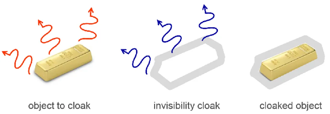
In the last ten years, several conceptually different cloaking techniques have been proposed [2]-[9]. A first approach, named transformation electromagnetic and originally introduced in [2]-[3], consists of covering the object with a properly engineered metamaterial cover that is able to guide the impinging field around the object itself, avoiding, in this way, any interaction of the external field with the object. This approach, schematized in Fig. 1, in principle works for any shape, dimension and constitutive material of the object, and it has also been verified experimentally in several configurations, see, e.g., [10]. Nevertheless, the design of such covers, as well as their practical realization, remains a non-trivial task since it requires the use of thick anisotropic and inhomogeneous artificial materials.
Another proposed general approach is the so-called scattering cancellation technique [6]. This approach is based on a different physical principle that has been schematized in Fig. 2: in this case, the cover surrounding the object does not inhibit the interaction of the external field with the object, but is instead designed such that the field scattered by the
object can be compensated by the field scattered by the cloak, leading, thus, to a significant reduction of total scattering. It is important to underline that the fact that the cloaked object is not “isolated” from the external electromagnetic field is not a weakness but, conversely, can be considered as an advantage of the scattering cancellation cloaking compared to the other techniques since, as discussed in the next Chapter, it has allowed to propose some unprecedented applications of cloaking technologies in both the antenna and sensor theory. Several practical realizations of this cloaking technique have been proposed over the years at microwave [11]-[12] and optical [13]-[17] frequencies and some sensor applications [18]-[20] have also been suggested.
Fig. 1: Schematic representation of the operation of a transformation electromagnetic-based cloaking device [2].
As a first limitation of this cloaking approach, it is possible to point out that single-layer scattering cancellation is effective in the scattering reduction of objects whose characteristic size is small comparable to the operational wavelength. This limitation is due to the fact that the scattering from an object is the result of the superimposition of different modes, whose number and amplitude is directly related to the object size. Since a single layer cloaking cover is only able to properly compensate the field of the dominant scattering mode, the use of mono-layer cloaks necessarily involves a limitation in the maximum size of the object to hide. Unfortunately, such restriction limits the application of cloaking technology in many scenarios where it is required to reduce the scattering of objects whose dimensions are comparable to or even larger than the wavelength. However, as I am going to show below, it is possible to generalize the scattering cancellation cloaking approach to multi-layer covers working for non-electrically small objects.
Secondly, since scattering cancellation cloaking is based on the destructive interference between the field scattered by the object and the one scattered by the cloak, the cloak design is strongly dependent on the shape and on the electromagnetic properties of the object to hide. However, this does not imply that the scattering cancellation cloaking of irregularly shaped object cannot be achieved. As far as the object dimensions are small compared to the operative wavelength (i.e., the quasi-static condition is satisfied), it is always possible to cancel the first scattering mode of the object through a scattering cancellation-based cloak. In the case of a regular geometry, as the 1D slab, the 2D cylinder, the 3D sphere, etc., it is possible achieving a closed form solution of the Mie scattering problem and, therefore, simplifying the cloak design. However, a numerical general solution can be easily found also for objects with arbitrary geometries, as have been proven in [21],[22].
Fig. 2: Schematic representation of the operation of a scattering cancellation-based cloaking device.
The first implementation of the scattering cancellation cloak foresaw the use of bulky volumetric epsilon-near-zero (ENZ) or epsilon-negative (ENG) metamaterials [11],[12]. However, recently, it has been proven that the scattering cancellation approach can be obtained by using covers made of thin metasurfaces such as the ones shown in Fig. 3. This approach, known as mantle cloaking [7],[8] is particularly promising especially at microwave frequencies due to its straightforward implementation [23] and to the availability of accurate analytical models [24]-[27] allowing to quickly achieve a working design. Moreover, since it is a scattering cancellation cloaking approach and, therefore, it does not electromagnetically isolate the hidden object, mantle cloaking can be successfully applied in different antenna scenarios, with substantial advantages both in the transmitting [28] and in the receiving [29] operation mode of an antenna.
In this Chapter I focus my attention of the theory beyond the mantle cloaking. First, in the nest Section it is investigate the analytical formulation of the mantle cloaking approach for a cylindrical geometry, which can be considered as the reference one for the design of cloaking devices for antenna applications. Finally, in the third Section it is derived the analytical models used to characterize and to design the metasurfaces required by the mantle cloaking.
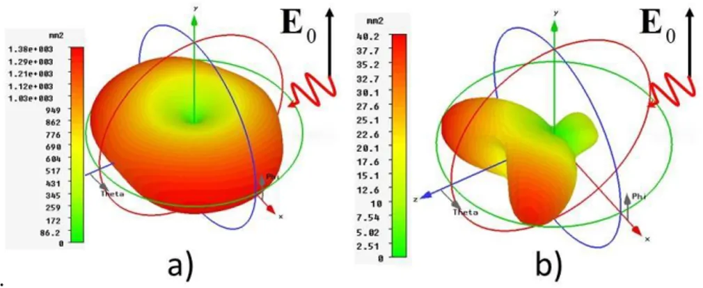
Fig. 3: Some examples of mantle cloaking devices for a spherical object [8].
1.2 Analytical formulation of the mantle cloaking for a
cylindrical geometry
Let us to considerer the generic scenario depicted in Fig. 4 in which an infinitely long cylinder composed by a generic material
,
and surrounded by a conformal metasurface is illuminated by an external normal incident electromagnetic plane wave0
jkxi
e
E
E
(i.e., whose wave vector is perpendicular to the axis of the cylinder). The radius of the cylinder is equal to a whereas the one of the metasurface is ac
a. Ametasurface is typically composed of deeply subwavelength elements and may be described by an averaged surface impedance, related to the tangential electric field
tan
sTM S
Z
E
J
, where Js is the induced average surface current density.My aim is to find a closed-form formula to evaluate the total scattering cross section of the cylinder in function of the electromagnetic parameters of the structure. For this purpose, I follow the analytical procedure described in [7],[30]. The starting point is the scalar wave equation 2
k2
0, which in cylindrical polar coordinatesr
, , z
reads as2 2 2 2 2 2
1
1
0.
r
k
r r
r
r
z
(1.5)Separable solutions of (1.5) that are single-valued functions of
are of the form
, ,
0, 1,... ,
jn jhz
n
r
z
Z
ne
e
n
(1.6)where
r k
2
h
2 and Zn is a solution to the Bessel equation, i.e., the Besselfunctions of first and second kind, Jn and Yn, of order n. The vector harmonics
generated by (1.6) are the following:
2 2 ˆ ˆ ,
j n hz n n n Z k h in Z e M r φ (1.7)
2 2 2 2 ˆ
ˆ ˆ ,
j n hz n n n n Z k h inZ hn k h Z e k N r φ z (1.8)where h is the separation constant whose value is dictated by the form of the incident field and the necessity of satisfying the boundary conditions at the boundaries between the cylinders and the surrounding medium.
There are two possible orthogonal polarization states of the incident wave: electric field polarized parallel to the z axis and electric field polarized perpendicular to the z
axis. I shall consider each of these polarizations in turn.
1.2.1 TM-polarization
I consider there the case in which the electric field of the incident plane wave is parallel to the axis of the cylinder, i.e.,
E
i
z
ˆ
E e
0 jkx. The first step consists in the expansions of the incident electric field in vector cylindrical harmonics. In order for the expansion to be finite atr
0
I must exclude the Bessel function Yn as the radiallydependent part of the generating function. Moreover, it is easy to understand from the form of Ei that
h
k
. Therefore, the expansion of the incidence field is: 1 1
,
i n n n n nA
B
E
M
N
(1.9)where the superscript
1
denotes the Bessel function of the first kind. By exploiting the orthogonality of the vector harmonics, it is easy to verify that
00,
,
n n n nE
j
A
B
E
k
(1.10)with k k0 if the incidence medium is the vacuum. Therefore, the expansion the incident electromagnetic field reads as follow
1
, ,
,
i n n nE
z
E
N
(1.11)Following a similar procedure, it is possible to expand into cylindrical vector harmonics also the electric field Es scattered by the overall system, the electric field
shell
inside the cylinder. In particular, the field Eshell is the superposition of an incoming and
an outgoing cylindrical wave whereas the fields Eint and Es are an incoming and an
outgoing cylindrical wave, respectively. In formulas, I can write:
3 3
,
s n n n n n nE
b
i
a
E
N
M
(1.12)
1 1
int,
n n
n n n nE
c
d
E
N
M
(1.13)
1 3 2 1 1 3 2 1
,
shell n n n n n n n n n ne
e
E i
i
f
f
E
N
N
M
M
(1.14)where the superscript 3 denotes the Hankel function Hn. The eight terms
2
...
n n
a
f
are unknown expansion coefficients that can be calculated by imposing the proper boundary conditions. The first four of these equations arise from the continuity of the tangential components of both electric and magnetic field at the interface ra (Fig. 5 - left):
int int int int.
shell z z shell shell z z shellE
r
a
E
r
a
E
r
a
E
r
a
H
r
a
H
r
a
H
r
a
H
r
a
(1.15)The remaining four equations can be derived imposing the double-boundary condition characterizing the metasurfaces at the second interface of the structure (Fig. 5 – right), i.e.,
ˆ
ˆ
.
ˆ
ˆ
shell c s i c s c shell c z z z z shell c s i c s c shell c i c s c s i c s c z z z z i c s c s i c s cE
r
a
Z
H
r
a
H
r
a
H
r
a
E
r
a
Z
H
r
a
H
r
a
H
r
a
E
r
a
E
r
a
Z
H
r
a
H
r
a
E
r
a
E
r
a
Z
H
r
a
H
r
a
r
r
r
r
(1.16)Fig. 5: (left) First and (right) second interface of the coated cylinder.
By solving the
8 8
systems returned by (1.15)-(1.16), it is possible to achieve an analytical expressions of the termsa
n...
f
n2. Among them, I are interested in the expressions of an and bn since they are directly related to the scattered field (1.12). Inparticular, the total scattering width (SW) of the coated cylinder (i.e., the scattering cross section per unit of length) can be evaluated as follows
2 2 2 0 1 02
2
.
sca n n nQ
b
b
a
k a
(1.17)Formula (1.17) shows that the overall scattering of an object is the superposition of different scattering modes each of them identified by a proper value of the integer index n. As an example, in Fig. 6, it is reported the contribution to the total scattering cross-section at f0 3 GHz of the first five scattering modes of an uncoated dielectric cylinder (i.e., Xs ) with relative permittivity equal to ε = 4 and ε = 10, respectively, as the
cylinder radius changes. As can be appreciated, as far the cylinder radius is small compared to the operative wavelength the only non-negligible contribution to the overall scattering is provided by the zeroth scattering mode. Since a metasurface can tailor a single scattering mode, it possible to obtain a cloaking phenomenon for objects that satisfy the so-called quasi-static condition, i.e., r
0/10.As an evidence, in Fig. 7 it is reported the variation of scattering width gain with the surface reactance of a mantle cloak for an infinitely long dielectric cylinder with relative permittivity ε = 10 and radius a = λ0/10. As it can be appreciated, depending on the cover
value of the cloak surface reactance Xs. This SW minimum is related to a dramatic
reduction of the object electromagnetic visibility and identifies a cloaking phenomenon. Please note that, for dielectric objects, the required surface reactance value is positive (i.e., inductive) whereas for metallic object a capacitive reactive sheet is required.
Fig. 6: SCS contribution of several scattering modes of a dielectric cylinder with relative permittivity equal
to ε = 4 and ε = 10, respectively, as the cylinder radius changes. The operation frequency is f0 = 3 GHz.
Fig. 7: Variation of the scattering width gain with the surface reactance of a mantle cloak for an infinitely long dielectric cylinder with permittivity ε = 10 and radius a = λ0/10.
For sub-wavelength dielectric cylinders, the ideal cloaking value of the cloak surface reactance can be calculated with the following expression [8]:
02
.
1
ideal sX
a
(1.18)Differently from the dielectric case, instead, in the metallic one the cloaking effect is generally quite narrowband and a more refined analytical approximation is required in order to avoid a gross evaluation of the ideal surface impedance. By expanding the Bessel and the Hankel functions describing the zeroth TM scattering mode contribution to the total SCS with proper Taylor series, I can derive the following formula for the case of TM incidence [24]:
2 2 0 0 2 2 4 4 6 6 0 0 0 2 2 2 2 2 2 2 0 0 0 16 4 ln / 4 256 4 4 4 4 .
c c c ideal s c c c c a a k a a X a k a k a k a a k a k a k (1.19)1.2.2 TE-polarization
I consider there the case in which the electric field of the incident plane wave is perpendicular to the axis of the cylinder, i.e.,
E
i
y
ˆ
E e
0 jkx. The main difference compared to the TM incidence regards the field expansion. For what concerns the incidence field, in this case it reads as follow: 1
, ,
,
i n n niE
z
E
M
(1.20)Also in this case, the field Eshell is the superposition of an incoming and an outgoing
cylindrical wave whereas the fields Eint and Es are an incoming and an outgoing
cylindrical wave, respectively. Exploiting the expansion (1.20), I can write:
1 1
int
n n
n n n nE
c
d
E
M
N
(1.21)
3 3
s n n n n n nE
b
i
a
E
M
N
(1.22)
1 3 2 1 1 3 2 1
shell n n n n n n n n n ne
e
f
E
i
i
f
E
M
M
N
N
(1.23)Similarly to the TM-case, by imposing the proper boundary conditions and solving the
8 8
systems, I can achieve the analytical expressions of the unknown coefficients. Then, by proper expanding the scattering coefficients an and bn in Taylor series, it ispossible to obtain the closed-form formulas to evaluate the ideal surface reactance able to suppress the first scattering mode under a TE incidence for both a dielectric and a metallic cylinder. However, the relative expressions are quite cumbersome and they are here omitted.
I conclude this Subsection with some observations: first, I underline that, for a cylindrical geometry, the TE scattering is generally significantly lower than TM, so the design of a cloak able to tailor also the scattering of this polarization may not necessarily be essential for all applications. However, it is equally important to note that the analysis developed here also apply to the case of electrically large objects, for which TE scattering may became stronger, as evident in Fig. 8. In these cases, multilayered mantle cloaks, described in the next Subsection, provide the necessary degrees of freedom to suppress higher-order TM and TE scattering harmonics.
Fig. 8: Normalized SCS of a dielectric cylinder with relative permittivity ε = 10 at 3 GHz for both TM and TE incidence as the cylinder radius changes.
Second, it is important to point out that TE scattering is usually the combination of several scattering orders with similar amplitudes, differently from what happens in the TM case for which it is possible to recognize a dominant contribution from the lower scattering harmonic. With a single-layer cover I can typically suppress one or two scattering orders and, therefore, the SCS gain in the TE case is inevitably lower
compared to the TM case. Also in this case, multilayered mantle cloaks may help achieving further total SCS reductions, since they allow the suppression of multiple scattering orders concurring to the overall TE scattering.
1.2.3 Multilayered mantle cloaks
As evident from the discussion of the previous Subsection, single-layer mantle cloaking devices are effective in the scattering reduction of objects whose characteristic size is small compared to the operational wavelength and for moderately narrow frequency range.
In this Subsection, it is proposed a generalization of the mantle cloaking approach to multi-layer covers working for non-electrically small objects and/or for broader frequency range. Here, it is considered the structure shown in Fig. 9, where an infinitely long cylinder with radius a and electromagnetic parameters
,
is surrounded by two conformal anisotropic metasurfaces with effective surface impedance tensor equal to1 s Z and Zs2, where: , , 0 , 1, 2. 0 TM i i s s TE i s Z Z i Z (1.24)
The radius of the metasurfaces are
a
1c
1a
anda
c2
2a
, respectively, and the object is illuminated by an external plane wave with electric field parallel (TM incidence) or perpendicular (TE incidence) to the cylinder axis.The electromagnetic analysis is analogous to the one developed for a single layer mantle cloak device. The only difference is related to the existence of another space region (the one comprised between the two metasurfaces) in which the electric field
,2
shell
TM
E
needs to be defined. The following expressions can be used: 3
3
, ,
, ,
s n n n n TM n nb
r
z
ja
r
z
E
M
E
N
(1.25)
,1 3 3 ,1 , 1 1 ,2 ,2 1, ,
,
,
, ,
,
,
shell TM n n n n n n n n n nf
r
f
r
z
z
je
e
r
r
z
z
E
N
M
N
M
E
(1.26)
,2 3 3 ,1 , 1 1 ,2 ,2 1, ,
,
,
, ,
,
,
shell TM n n n n n n n n n nh
r
h
r
z
z
jg
g
r
r
z
z
E
N
M
N
M
E
(1.27)
int 1 1, ,
, ,
n n n n
TM n nc
r
z
d
r
z
E
N
E
M
(1.28)Please note that, for the reader convenience, the incoming cylindrical waves have been highlighted using a blue font, whereas the outgoing cylindrical wave are written in red. Analogous expressions can be easily derived for the TE polarization.
Fig. 9: Section of a multilayer mantle cloaking in the cylindrical geometry.
The 12 12 analytical systems whose solutions return the scattering coefficients can be easily obtained using expressions (1.15)-(1.16). In particular, equations (1.16) need to be applied both the first (i.e.,
r
a
1c) and to the second (i.e.,2
cr
a
) interface of the coated object. The generalization of this electromagnetic analysis to a generic N-layer cloak device is straightforward.MULTIBAND AND BROADBAND CLOAKING
Multiband cloaking is naturally enabled using bilayer cloaks. In this Subsection, I consider a conductive target of cross-section 2a
0 5, where
0 is the wavelength a 3 GHz, as this represents a target of practical interest. Using the analytical formulationdeveloped above it is possible to calculate the required surface impedance values to simultaneously reduce the scattering at 2 GHz and 3 GHz for conformal aspect ratios
1
1
1.01
a a
c
and
2
a a
c2
1.50
, such that the overall covered object is still2
0
2
a
c
0.3
. In Fig. 10, the scattering characteristics are shown for this example, targeting the two dominant scattering modes at the two design frequencies. In the top panel, the surface impedances (X
s,1
1.5
,X
s,2
184.2
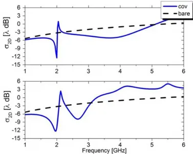
) are properly selected to suppress the monopolar and the dipolar scattering mode at 2 and 3 GHz, respectively. As expected, I see strong scattering suppression at 2 GHz, where the monopolar term is dominant. Targeting the dipolar term at 3 GHz, a more broadband suppression is achieved at higher frequencies where it becomes more relevant. Here I see a strong suppression of -10.2 dB at 2 GHz with a wide 3 dB bandwidth between 3.3-4.3 GHz.Fig. 10: (Top panel) Scattering profile targeting the monopolar mode at 2 GHz and the dipolar at 3 GHz. (Bottom panel) Scattering profile targeting the monopolar mode at 2 and 3 GHz.
In the bottom panel of Fig. 10, it is next show the effect of cancelling the monopolar term at both frequencies with the same aspect ratios. The required surface impedances (
,1
1.6
s
X
,X
s,2
113.7
) now have a tighter dual-band operation of -9.1 dB at 2GHz and -5.6 dB at 2.7 GHz. Fig. 10 demonstrates two significant applications for cloaking designs under the cancellation condition for the chosen scattering modes. It should be emphasized here that I selected these two modes because they dominate the scattering at the two target frequencies, but in general they may not always be the best
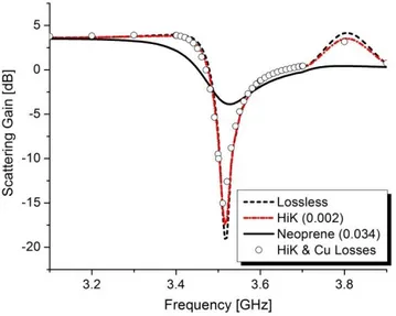
choice, as the interactions between the chosen surfaces may enhance other higher-order modes (HOM), especially for larger targets. The effect of the coupling interactions between these residual in-band modes is seen in Fig. 10, which either slightly detunes the minimum SW, or limits the scattering suppression or overall bandwidth.
CLOAKING OF NON-ELECTRICALLY SMALL OBJECTS
I consider here the possibility to exploit the multilayered mantle cloaking devices to suppress more than one scattering order at the same frequency and, therefore, cloaking non-electrically objects. As an example, in Fig. 11 I report the SCS contribution of the first three scattering modes of a dielectric cylinder with permittivity ε = 10 at a frequency f0 =
3 GHz as the cylinder radius changes for both TM and TE polarization.
For a
0 / 2.8535 mm the total SCS for both the polarizations is the superposition of three scattering modes. As can be appreciated in Fig. 12, with a properly designed bi-layer anisotropic mantle cloak device (a
c1
1.04
a
,a
c2
1.06
a
c1,X
TMs ,1
37.6
,,1
11.8
/
TE sX
sq
,X
s TM2,
272.4
, 2 ,
19
s TEX
) it is possible to reduce the object SCS of 6 dB for the TM polarization and 10 dB for the TE polarization. The use of a tri-layer mantle cloaking device (Fig. 13) allows to achieve a bigger reduction equal to 12 dB and 9 dB of the TM and TE scattering, respectively. Please note that, the geometrical and electromagnetic values of the cloaks has been obtained with a numerical minimization of the analytical formulas expressing the scattering of a cylinder cloaked with a N-layered cover.Fig. 11: SCS contribution of the first three scattering modes for a dielectric cylinder with relative permittivity ε = 10 at a frequency f0 = 3 GHz for both TM (left) and TE (right) incidence.
Fig. 12: SCS contribution of the first three scattering modes for a dielectric cylinder with relative permittivity ε = 10 at a frequency f0 = 3 GHz coated with a bi-layer mantle cloak device as the
cylinder radius changes for both TM (left picture) and TE (right picture) incidence.
Fig. 13: SCS contribution of the first three scattering modes for a dielectric cylinder with relative permittivity ε = 10 at a frequency f0 = 3 GHz coated with a tri-layer mantle cloak device as the
cylinder radius changes for both TM (left picture) and TE (right picture) incidence.
1.3 Metasurface analytical models
In the previous Section, I have investigated the theoretical basis of the mantle cloaking approach. In particular, it has been proven that the use of one or more metasurfaces exhibiting a desired value of their own intrinsic surface reactance is able to provide a cloaking effect, i.e., a nullification of the object scattering. At microwave frequencies, a metasurface can be realized simply using a patterned metallic surface. In this Section, I summarize the results of [24]-[27] in which the design of microwave metasurfaces for cloaking applications for both TM and TE incidence polarization has been deeply investigated.