Università degli Studi di Ferrara
DOTTORATO DI RICERCA IN
"FISICA"
CICLO XXVIICOORDINATORE Prof. Vincenzo Guidi
Industrial R&D on Innovative Surface Treatments
for an Ecological Descaling of “Acciaierie Valbruna”
Stainless Steel Wire Rods in Replacement
of the Traditional Acid Etching
Settore Scientifico Disciplinare ING–IND/27
Dottorando Tutore
Dott. Vlada Pastushenko Prof. Vincenzo Palmieri
___________________ ___________________
(firma) (firma)
3
Acknowledgments
This research was done in a framework of the contract between “Acciaierie Valbruna” and Consorzio Ferrara Ricerca. I would like to take this opportunity to express my sincere gratitude to “Acciaierie Valbruna” for a chance to work on such an exciting ecological project, and CFR for their support in communication between our research group and industries.
On this project besides me have worked Cristian Pira, who has studied the mechanical pre-treatment of stainless steel and assembled the prototype plants for electropolishing. And Giorgio Keppel, who provided all the drawings and was involved in building the industrial plant for electropolishing.
I would like to express my special appreciation and thanks to my advisor Professor Vincenzo Palmieri. I would like to thank you for allowing me to grow as a research scientist.
5
Contents
Acronym ... 8 Abstract ... 9 Introduction ... 11 1.1. Steel production ... 111.2. The Iron - Iron Carbide phase diagram. ... 13
1.2.1. Cast Iron. ... 14
1.3. Alloy types and application. ... 15
1.4. Thermal treatment and scale formation. ... 17
1.5. Cleaning of stainless steel. ... 19
1.5.1. Descaling. ... 19
1.5.2. Acid etching. ... 20
1.5.2.1. Typical procedure of acid pickling stainless steel. ... 22
1.5.2.2. Organic acid pickling solutions. ... 23
1.6. Electrochemical etching and polishing. ... 24
1.6.1. Benefits and disadvantages of electropolishing. ... 25
1.6.2. Solutions for electropolishing stainless steel. ... 26
2. Ionic liquids as new electrolytes... 29
3. Passivation. ... 33
3.1. Chemical passivation. ... 33
3.2. The anodic passivation. ... 34
3.2.1. Corrosion protection. ... 35
4. Experimental part. ... 37
4.1. The characterization of the scale layer. ... 37
4.1.1. The characterization of thickness and anisotropy. ... 38
4.1.2. Morphology and microstructural characterization. ... 38
4.2. Characterization of the different steel types. ... 40
4.3. Study of the effectiveness of pre-finish treatment. ... 57
4.3.1. Study of the technique of high pressure rinsing. ... 57
4.3.1.1. The effect of different pressure (100-800 bar). ... 57
4.3.1.2. Study of the influence of the jet angle and different nozzle geometry…. ... 60
4.3.1.3. Study of the influence of adding the abrasive. ... 62
4.3.2. Study of the effectiveness of “dry ice” -blasting (CO2 -blasting). ... 64
6
5. Green Electropolishing. ... 69
5.1. The characterization of samples etched in the standard solution. ... 69
5.2. Study of the possibility of ionic liquids to electrochemically polishing of stainless steel. ... 70
5.2.1. Ionic liquids as alternative electrolytes. ... 71
5.2.2. Testing the new solutions consist of ionic liquids. ... 71
5.3. Study the other eutectics based on Choline Chloride. ... 78
5.3.1. Deviations of the eutectics and study the process parameters. ... 79
5.3.2. The influence of ultrasound during the electropolishing. ... 82
5.4. Study of the contents of wastewater. ... 84
5.5. Selecting the best solution. ... 84
5.6. Analysis of the applicability of the alternative solution. ... 88
5.6.1. The measurements of solution lifetime. ... 88
5.6.2. Vapours analysis. ... 90
5.6.3. Estimation of the process time. ... 90
5.7. Additional tests with Eutectic “O”. ... 91
5.7.1. Electropolishing martensitic steel and steel doped with sulphur. ... 91
5.7.2. Comparison of the electrolytes with carboxylic acid pure and technical grade. ... 92
5.7.3. Study of the influence of preliminary treatment... 94
5.8. Optimization of the parameters of electropolishing in ionic liquids. ... 95
5.8.1. Study of lower working temperatures. ... 96
5.8.2. Study of the different ratios Choline Chloride – Carboxylic acid. .... 98
5.8.3. Study of the influence of additives in Eutectic “O”. ... 99
5.8.4. Study of the influence of water on electropolishing process in ionic liquids……… ... 101
5.8.5. Search of a new Choline chloride based ionic liquid for electropolishing. ... 103
5.8.6. Summary of the ionic liquids mixtures, applicable to the electropolishing of the stainless steel. ... 106
5.9. Study of the recycling of ionic liquid. ... 107
5.9.1. Study of the velocity of metal dissolving in fresh solution and recycled. ………..109
5.10. Study of the possibility to use AC power supply. ... 110
6. The first test in the construction of the new cleaning machine. ... 113
7
6.2. Testing the material for tank. ... 115
6.3. The construction of electrochemical plant for descaling stainless steel coils close to real conditions. ... 118
6.3.1. Preparation of the solution and study of the process parameters. .. 120
6.4. The design of prototype for electropolishing of the wire rods in ionic liquid…. ... 122
7. Study of the steel passivation after electropolishing. ... 125
7.1. Corrosion test in seawater. ... 131
7.2. Test on atmospheric corrosion for the wire rods. ... 133
8. Aqueous solution for descaling stainless steel. ... 137
8.1. Study of the possibility of electropolishing in aqueous electrolytes. ... 137
8.1.1. Chemical etching of stainless steel. ... 137
8.1.2. Electrolytic cleaning in organic acids. ... 138
8.2. Pulse reverse finishing. ... 139
8.2.1. Pulse reverse electropolishing in aqueous solutions. ... 140
8.3. Alternative solution for descaling stainless steel. ... 143
8.3.1. Organic acid solution for electropolishing. ... 143
8.3.2. Inorganic acid solution for electropolishing. ... 145
8.4. Study of the parameters for electropolishing stainless steel in inorganic acid solution. ... 146
8.5. Electropolishing of stainless steel coils in Solution “S”. ... 148
8.5.1. Comparison of the applicability aqueous solutions for treatment stainless steel ... 151
8.6. Selecting the best parameters for electropolishing in alternative solution….. ... 152
9. The design of technological demonstrator for the wire rods descaling. ... 155
Conclusions ... 159
List of figures ... 163
List of tables ... 169
8
Acronym
AISI - American Iron and Steel Institute ChChl – Choline Chloride
CA – Carboxylic Acid
DES – Deep Eutectic Solvents EG – Ethylene Glycol
EP – Electrochemical Polishing
EDX – Energy Dispersive X-ray Spectroscopy HPWR – High Pressure Water Rinsing
IL – Ionic Liquid OV – Over Potential PS – Power Supply T – Temperature
9
Abstract
This work deals with an industrial research on ecological innovative descaling treatments for stainless steels, in substitution of the acid etching process: from the study and the research on samples, the most efficient techniques and their application to industrial purpose are explained.
The research has basically covered the study of two pre-finishing treatments (high pressure water blasting and “dry ice”-blasting) and two etching treatments (electropolishing with ionic liquids and in aqueous media).
In the field of stainless steels, the surface oxide of iron Fe (III) is combined with the multiple elements added to alloys in order to increase their characteristics (carbon, chromium, nickel and other). Moreover, the surface oxide is presented as a layer very tenacious and compact. In addition, heat treatment leads to the formation of a layer without chromium more readily attacked by oxygen from the atmosphere. Surface treatments are required to remove the surface oxide and recover the chromium layer.
The chemical pickling, that is one of the most common etching processes, depends on many factors, such as the size of the pieces, the type of plant, the type of alloy et al. In general, the traditional solutions contain from 10% to 20% by weight of nitric acid, and 1% to 5% by weight of hydrofluoric acid. The oxidizing environment is provided by nitric acid, which effectively removes the oxide surface, and is subsequently used without the hydrofluoric acid to restore the passive layer (passivation). From the environmental point of view, however, the use of this reagent is very costly:
• Air pollution: the formation of nitrogen oxides (NOx) during the process causes fumes and vapours. These gases are harmful to health, highly polluting (production of acid rain) and extremely aggressive towards metals.
• Water pollution: the high concentration of nitrates and nitrites is one of the causes of eutrophication. In particular, nitrites may form carcinogenic compounds such as nitrosamines, which can enter the food chain through fish.
• Health and safety: hydrofluoric acid is highly corrosive and a poison. It should be handled with extreme attention, using protective equipment and safety precautions. Once absorbed into the blood through the skin, it reacts with blood calcium and may cause cardiac arrest. In addition, it combines with calcium and
10
magnesium of the bones. Since its action can be delayed for many hours, it can distribute throughout the body, causing the erosion of bones.
These features have shown how the study of alternative "green" treatments is crucial.
11
Introduction
1.1. Steel production
Today there are hundreds types of steels graded by different classifications: European standards, International Organization for Standardization (ISO), ASTM International and the Society of Automotive Engineers (SAE). Two of the most widely used series are 302 and 304 steels in equipment construction, such as vacuum systems. The grades range from steels, magnetic steels, to stainless steel. Construction irons and steels include buildings, bridges, heavy-duty equipment, vehicles, and "tin" cans.
As a very brief resume of iron and steel fabrication [1], major iron ores are the iron oxides, such as hematite, Fe2O3; magnetite, Fe3O4; siderite, FeOxH2O and
the pyrite, FeS2. The iron ores are initially kiln fired and roasted in a vertical blast
furnace to obtain "pig iron" (4% carbon; 3% silicon; phosphorus and sulphur). The phosphorus makes it brittle when cold; the sulphur makes it brittle when hot.
Figure.1.1: Production of the steel from the iron ore in basic-oxygen furnace [2]. Cast iron is made from the initial “pig iron” as white cast iron with a high cementite, Fe3C content; and as grey cast iron with some cementite separation into
iron and graphite. Wrought iron is made by removing the carbon with air blowing through the iron mass. Silicon iron (15% Si) is brittle but very acid resistant and used as holding vessels, crucibles, piping and linings in acid processing equipment. Manganese iron is tough. With 1-7% Mn used for machine tooling; with >7% Mn for heavy-duty equipment, such as rock crushers.
12 Figure 1. 2: F low diagr am showi ng the princ ipal proc ess st eps i nv olve d in conv erti ng raw mate rial s int o the m ajor p roduc t f orms, e xc ludi ng c oated produc ts [3] .
13
Nickel steel has a great tenacity and is a primary construction steel with 0.5% Ni, and for armour plate with 3-5% Ni. Tungsten steel holds a temper at high temperatures, such that it is used for lathe cutting tools, knives, and scalpels. Both molybdenum and cobalt steels are similar. Chromium steel with 12—15% Cr is corrosion resistant and used for tools, equipment and armour plate. With >18% Cr it is stainless steel.
1.2. The Iron - Iron Carbide phase diagram.
Figure 1.3 shows the equilibrium diagram for combinations of carbon in a solid solution of iron. The diagram shows iron and carbons combined to form Fe-Fe3C at the 6,67% C end of the diagram. The left side of the diagram is pure iron combined with carbon, resulting in steel alloys. Three significant regions can be relative to the steel portion of the diagram. They are the eutectoid E, the hypoeutectoid A, and the hypereutectoid B. The right side of the pure iron line is carbon in combination with various forms of iron called -iron (ferrite), -iron (austenite), and -iron. [4]
-ferrite. This phase in an interstitial solid solution of carbon in BCC iron crystal lattice. Stable form of iron at room temperature. The maximum solubility of C is 0.022 wt %. Transforms to FCC γ-austenite at 912 °C.
γ-austenite. The interstitial solid solution of carbon in FCC iron. The maximum solubility of C is 2.14 wt %. Transforms to BCC δ-ferrite at 1395 °C. It is not stable below the eutectic temperature (727 ° C) unless cooled rapidly.
δ-ferrite. The interstitial solid solution of carbon in BCC iron crystal lattice as -ferrite but with a greater lattice constant. It is stable only at high temperature above 1394 °C. Melts at 1538 °C.
Fe3C (iron carbide or cementite). This intermetallic compound is metastable, it remains as a compound indefinitely at room temperature, but decomposes (very slowly, within several years) into α-ferrite and carbon (graphite) at 650 - 700 °C. [5]
14
Figure 1.3: Fe-Fe3C phase diagram. [4]
1.2.1. Cast Iron.
Cast irons are a family of ferrous alloys with a wide range of properties, and as their name implies, they are intended to be cast into the desired shape instead of being worked in the solid state. Unlike steels, which usually contain less than about 1% carbon, cast irons normally contain 2 to 4 %carbon and 1 to 3% silicon.
Cast irons make excellent casting alloys since they are easily melted, are very fluid in the liquid state, and do not form undesirable surface film when poured. The wide industrial use of cast irons is due mainly to their comparatively low cost and versatile engineering properties.
Four different kinds of cast irons can be differentiated from each other by the distribution of carbon in their microstructures: white, gray, malleable and ductile iron. 5
White cast iron. These contain less Si or C than grey cast irons and undergo faster cooling. This results in cementite forming in favour of graphite. Again the name ‘white’ has little to do with the ordinary appearance of the alloy,
15
but rather refers to the fracture surface. White cast irons are much more brittle than grey cast irons, and so their fracture surfaces are reflective, leading to their classification as ‘white’.
Gray Cast Iron. Usually contain more carbon or silicon than white cast irons, and require a lower cooling rate. They are called ‘grey’ cast irons not because of their colour, but due to the appearance of a fractured surface. Grey cast irons are quite ductile and have unreflective fracture surfaces. Gray cast iron has good machinability at hardness levels that have good wear resistance, resistance to galling under restricted lubrication, and excellent vibration damping capacity.
Ductile iron is a family of cast graphitic irons that possess high strength, ductility and resistance to shock. Annealed cast ductile iron can be bent, twisted or deformed without fracturing. Its strength, toughness and ductility duplicate many grades of steel and far exceed those of standard gray irons. Yet it possesses the advantages of design flexibility and low cost casting procedures similar to gray iron.
Malleable cast iron is produced from white cast iron, which is made from hot liquid iron with certain chemical components. The white cast iron needs to be treated by malleablizing, such as graphitizing or oxidation and decarbonization, and then its metallographic structures or chemical components will be changed, so can become into malleable cast iron. [6]
1.3. Alloy types and application.
Stainless steel is not a single alloy: the name applies to a group of iron-based alloys containing a minimum 10.5% chromium. Other elements are added to improve the corrosion resistance and heat-resisting properties, enhance mechanical properties, and/or improve fabricating characteristics.
There are over 50 stainless steel grades that were originally recognized (AISI). A steel corrosion resistance, weldability, mechanical properties are largely determined by metal microstructure (see figure 1.4). This is determined by the steel chemical composition. As per EN 10088, stainless steels can be divided into the following, basic, microstructure-dependent groups:
• Martensitic. • Ferritic. • Austenitic.
16 • Austenitic-ferritic (duplex). [7]
As they are normally added to increase corrosion resistance, the various alloying elements have a large impact on the ease with which a stainless steel can be pickled (pickleability). It is the proportions of the different alloys that have a significant effect on the pickleability of stainless steel. Consequently, the higher the alloy content (i.e. the corrosion resistance), the more difficult it is to pickle the steel.
Figure 1.4: Typical microstructures of different stainless still grades.[7] The most basic grades are the iron-carbon-chromium alloys. These fall into two groups – martensitic and ferritic.
Martensitic stainless steels generally contain only from 11 to 17% of chromium and have a higher carbon content than the ferritic grades. The steels in this group are characterised by high strength and limited corrosion resistance. They are mainly used where hardness, strength and good wear resistance are required (e.g. turbine blades, razor blades and cutlery).
Ferritic stainless steels are more corrosion resistant than the martensitic grades, but less resistant than the austenitic grades. The most common of these steels contain either 12% or 17% of chromium – 12% of steels are used mostly in structural applications and automotive applications (exhaust systems) while 17% steels are used for catalytic converters, housewares, boilers, washing machines and internal building structures.
17
This lower resistance means they are “easier” to pickle. In other words, to avoid the risk of overpickling, they need a shorter pickling time or a less aggressive pickling agent. The addition of nickel to the austenitic and austenitic-ferritic steels further improves their corrosion resistance.
Austenitic is the most widely used type of stainless steel. It has a nickel content of at least 7%. This gives it non-magnetic properties, good ductility and good weldability. Austenitic steels can also be used throughout a wide range of service temperatures. Applications for which austenitic stainless steels are used include housewares; containers; industrial piping; tanks; building structures. This type of stainless steel dominates the market.
Austenitic-ferritic (duplex) stainless steels have a ferritic and austenitic lattice structure (hence duplex). To give a partly austenitic lattice structure, this steel has some nickel content. The duplex structure delivers both strength and ductility. Duplex steels are mostly used in the petrochemical, paper, pulp and shipbuilding industries.
1.4. Thermal treatment and scale formation.
After stainless steel is formed, most types must go through an annealing step. Annealing is a heat treatment in which the steel is heated and cooled under controlled conditions to relieve internal stresses and soften the metal. Some steels are heat treated for higher strength. However, such a heat treatment, known as age hardening, requires careful control for even small changes from the recommended temperature, time, or cooling rate that can seriously affect the properties. Lower aging temperatures produce high strength with low fracture toughness, while higher-temperature aging produces a lower strength, tougher material.
Though the heating rate to reach the aging temperature (482 to 537 ˚C) does not affect the properties, the cooling rate does. A post-aging quenching (rapid cooling) treatment can increase the toughness without a significant loss in strength. Such a process involves water quenching of the material in a 1.6 ˚C ice-water bath for a minimum of two hours.
The type of heat treatment depends on the type of steel. Austenitic steels are heated to above 1037 ˚C for a time depending on the dimensions. Water quenching is used for thick sections, whereas air-cooling or air blasting are used for thin sections. If cooled too slowly, carbide precipitation can occur. This build up can be
18
eliminated by thermal stabilization. In this method, the steel is held for several hours at 815 to 871 ˚C. Cleaning part surfaces of contaminants before heat treatment is sometimes also necessary to achieve proper heat treatment.
Hot rolling is a metalworking process that occurs at a temperature above the recrystallization temperature of the material. The starting material is usually semi-finished casting products such as slabs, blooms, or billets. The cast microstructure is broken down and deformed during processing and the deformed grains recrystallize, which maintains an equiaxed microstructure (a structure in which the grains have approximately the same dimensions in all directions) and prevents the steel from work hardening. [8]
Figure 1.5: The hot rolled rod coil.
After these processing steps, the surface has dark non-uniform appearance called “scale”. Scaling should be distinguished from rusting, which involves the formation of hydrated oxides. Scale usually is an iron oxides consisting of iron (II) oxide (FeO), iron (III) oxide (Fe2O3), and iron (II, III) oxide (Fe3O4, magnetite). It is usually less than 1 mm thick and initially adheres to the steel surface. The surface chromium has been lost during the high temperature processing steps, and without removal of the scale, stainless steel would not provide the expected level of corrosion resistance.
19 1.5. Cleaning of stainless steel.
Stainless steels need to be cleaned not only for aesthetic considerations but to preserve corrosion resistance. Stainless steel is protected from corrosion by a thin layer of chromium oxide. Oxygen from the atmosphere combines with the chromium in stainless steel and form the passive chromium oxide film that protects from further corrosion. Any contamination of the surface by dirt, or other material, hinders this passivation process and traps corrosive agents, reducing corrosion protection. Thus, some form of the cleaning is necessary to preserve the appearance and integrity of the surface. Stainless steels are easily cleaned by many different methods.
In selecting a metal cleaning process, many factors must be considered, including:
1) the nature of the scale to be removed; 2) the substrate to be cleaned;
3) the degree of cleanliness required;
4) the environment impact of the cleaning process; 5) the cost consideration;
6) the total surface area to be cleaned; 7) effects of previous processes; 8) rust inhibition requirements; 9) materials handling factor;
10) the surface requirements of subsequent operations, such as phosphate conversion coating, painting, or plating. [9]
1.5.1. Descaling.
Descaling is the removal of heavy, tightly adhering oxide films resulting from hot-forming operations, thermal treatments (such as annealing or hardening), or welding. [9] Since most stainless steel products received from the producing mill have been etched, descaling is required only because of subsequent manufacturing operations. There are basic methods used for removing rust and scale from metal parts:
– abrasive blasting (dry or wet); – tumbling (dry or wet);
20 – brushing;
– acid etching (or pickling); – salt bath descaling; – alkaline descaling;
– electrochemical polishing (or etching). [9]
Abrasive blasting is defined as an operation in which materials are cleaned by the abrasive action of any metal shot or mineral particulate propelled within a gas or liquid. Blasting cannot be considered as a complete cleaning procedure in itself. Tumbling is often the least expensive process for removing rust and scale from metal parts. Size and shape of parts are the primary limitations of the process. Etching in hot, strong solutions of acids is used for complete removal of scale from mill products and fabricated parts.
Electrolytic etching, although more expensive than usual pickling, can remove scale twice as fast and may prove economical where the time is limited.
Salt bath descaling is an effective means of removing or conditioning scale on stainless steels. Several types of salt baths either reduce or oxidize the scale. Various baths operate within a temperature range of 400 to 525 °C.
Alkaline descaling or alkaline derusting is used to remove rust, light scale, and carbon smut. Alkaline descaling is more costly and slower in its action than acid pickling, but no metal is lost using the alkaline method, because chemical action stops when the rust or scale is removed. Alkaline descaling also allows complete freedom from hydrogen embrittlement.
Electrochemical polishing. A less commonly used polishing technique is electrolytic polishing. Electrolytic polishing, known as anodic dissolution. In electropolishing, the metal is removed ion by ion from the surface of the metal object being polished.
1.5.2. Acid etching.
When planning an acid etching operation, it is necessary to know the type of stainless steel and its metallurgical and physical condition. Since the various stainless steels have different alloy compositions, they behave differently when exposed to etching acids. In addition, stainless steel parts that have been sensitized by welding or thermal treatment, or parts in a highly stressed condition, may be more susceptible to corrosive attack and thus require
21 special attention [10].
Figure 1.6: Mixed-acid etching line. [8]
The most commonly acids used for pickling stainless steels are nitric (HNO3), hydrofluoric (HF), sulphuric (H2SO4) and hydrochloric (HCl).
Nitric acid is oxidizing, whereas the others are reducing. Nitric acid tends to promote and preserve the corrosion-resistant qualities of stainless steels; it does not act to destroy the microscopically thin oxide surface film that gives stainless steels their corrosion resistance. Its oxidizing behaviour accounts for the fact that when alone or in solution with water, nitric acid will not dissolve and remove oxide scale from stainless steels.
Other acids accomplish descaling by reducing the oxides of which scale is composed. At the same time, they also reduce the protective oxide film on stainless steel and thus lay the underlying metal open to corrosive attack.
Because of the inherent characteristics of oxidizing and reducing acids, mixtures of the two acid types are used for pickling stainless steels. The most frequently used solution is a combination of nitric and hydrofluoric acids. They combine the scale-removing feature of the reducing acid constituent and the base metal protecting or passivating action of the nitric. By changing the relative proportions of these two acids in an aqueous solution, a wide range of strengths
22
is obtainable, which can still be further manipulated by varying temperatures. Solutions of sulphuric acid find their main use as a preliminary step in descaling. Sulphuric acid provides a quick initial attack on scale deposits, and it is always followed by the much more controllable nitric/hydrofluoric treatment.
Hydrochloric acid solutions behave similarly to sulphuric acid mixtures. Since the action of hydrochloric acid on both oxide scale and base metal is exceedingly rapid, it must be used with extreme caution. Unlike sulphuric acid, however, hydrochloric acid produces ferric chloride that is an active pitting agent. As the salt content builds up in the bath, pitting becomes quite rapid. For that reason, solutions can be used but for a short time and should be discarded as soon as any tendency toward pitting attack becomes apparent.
Hydrofluoric acid is never used alone. Because of the hazards connected with its handling, users should observe strict safety precautions [8].
1.5.2.1. Typical procedure of acid pickling stainless steel.
Mixtures of nitric and hydrochloric acids in water are the most effective and most widely used solutions for pickling the chromium-nickel stainless steel. The solutions can vary from 5 to 25 % of nitric acid and from 0,5 to 3 % of hydrofluoric (both by volume). For light scale, 12-15% nitric and 1 % of hydrofluoric is satisfactory. For the heavier oxides, the amount of hydrofluoric acid is higher, 2-3%. Bath temperature ranges from 50 to 60 ˚С. As higher the temperature is, as faster is the descaling, but because of acid evaporation, it is better to avoid higher temperature. The immersion time is from 10 to 15 minutes. The rinsing in water should follow pickling to remove any acid residues and after drying.
The sulphuric acid solution can be used as a preliminary step for this use 8-10% solution of concentrated sulphuric acid in water at 65-70 ˚C. Immerse for 5 minutes, rinse quickly with clean hot water, and after immerse in nitric/hydrofluoric acid bath and follow the procedure as previously described.
To avoid the hazardous hydrofluoric acid, it may be replaced with hydrochloric acid. Hydrochloric acid is extremely corrosive to stainless steel, so we need to be very accurate in immersion time and acid concentration. Nitric/hydrochloric acid solution is good for one-time-use job when you need to clean a single piece. Hydrochloric acid promotes the formation of ferritic chloride
23
in the bath; therefore, these solutions must be limited to a short time use if pitting attack is to be avoided.
Table1.1: The etching solutions for stainless steel. [11]
№ Solution Conditions 1 Sulphuric acid, 400 - 450 g/l Hydrochloric acid, 250 - 300 g/l SAS, 3 - 5 g/l Time, 60 min Temperature, 15 - 30 ˚C 2 Nitric acid, 220 – 240 g/l Sodium fluoride, 20 – 25 g/l Sodium chloride, 20 – 25 g/l Time, 60 min Temperature, 15 - 30 ˚C
3 Sulphuric acid, 80 – 110 g/l Nitric acid, 70 – 80 g/l Hydrofluoric acid, 15 – 50 g/l
Time, 10 - 60 min Temperature, 15 - 30 ˚C
1.5.2.2. Organic acid pickling solutions.
Organic acid chelates can be used to clean light oxides or scales and free iron particles from stainless steel surfaces. The organic compounds combine acid solution activity with passivant and buffering properties. Light scale residues can be solubilized in dilute solutions of ammonium citrate. Treatments of this type are satisfactory for final cleaning of fabrications for the food and chemical industry. A concentration of 3 to 5 % organic acid is preferred, and this solution is adjusted with ammonium hydroxide to a pH of between 3 and 4. An operating temperature of 80 ˚C will produce good cleaning within acceptable time cycles.
The iron particles may contaminate stainless steel surfaces because of shot blasting or machining. This free iron decreases the corrosion resistance. The ammonium citrate combined with anionic or non-ionic wetting agents are effective in removing these metal particles. An operating temperature of 80 °C and concentrations of 2 to 5 %.
Glycolic acid, formic acid, etc. are used in many equipment cleaning operations including pharmaceutical processing equipment, whiskey storage tanks, steam generators, and nuclear reactors. In addition to their ability to combine with many other chemical compounds, the advantages of using acids of this type for these applications include the low corrosion rate experienced, ability
24
to hold iron in solution, and safe handling properties. A number of manufacturers of these compounds have detailed descriptive literature of specific formulations that may be employed for cleaning stainless steel surfaces. 10
1.6. Electrochemical etching and polishing.
Electrochemical polishing of metal is one of the anodic metal processing, which results in the dissolution of the metal surface layer. The formation of a new surface layer with a lower micro-roughness, the smoothing of surface relief that does not contain cracks, foreign inclusions, hidden defects. This process utilizes a reducing acid environment in conjunction with substantial DC. It smooths the surface and leaves a shiny appearance. Moreover, more importantly it acquires better performances such as increased endurance limit, durability, fatigue resistance, elastic limit, and corrosion resistance. It is often used in applications where extreme cleanliness is necessary, for example in the pharmaceutical, semiconductor and dairy industries.
Figure 1.7: Typical electropolishing setup and surface profiles.
A typical electropolishing installation is similar in appearance to an electroplating line (see figure 1.7). The tank fabricated from plastic or steel with lining is used to hold the chemical bath. A lead, copper or stainless steel cathode immerses into the bath and connect to the negative (-) side of the power supply. The
25
working pieces are coupled to the positive (+) side. During the electropolishing, the metal is dissolved from the anodic electrode, passing in the solution and forms soluble salt of the metal.
Cathode (+): 2H+ + 2e- H2↑;
Men+ + ne- Me;
Anode (-): Me Men+ + ne- ;
2H2O O2↑+ 4H+ + 4e-, where Me is metal (stainless steel).
All components of stainless steel – iron, chromium and nickel – undergo this reaction simultaneously, producing a controlled smoothing of the surface. Some metallic ions are deposited on the cathodes, which require regular cleaning. Several side reactions also occur, creating by-products that must be controlled to produce the highest possible quality of electropolishing.
1.6.1. Benefits and disadvantages of electropolishing. Benefits of electropolishing:
– bright appearance;
– absence of abrasive scratches;
– improved fatigue strength due to stress relieving and defects free surface; – lower coefficient of friction due to smoother surface
(reduced microasperities);
– better corrosion resistance;
– allows processing fragile and delicate parts. Disadvantages of electropolishing:
– rough surface defects cannot be removed;
– electropolishing multiphase alloys may cause roughening due to selective dissolution of different phases.
26
Figure 1.8: A microscopic view of the same surface before and after electropolishing shows that the process produce clean metallic surface. [12]
The result can be reproducible with a high degree of precision, so components with tight tolerance can also be treated safely. On figure 1.8, we can see that electrochemical polishing produces the clean surface.
1.6.2. Solutions for electropolishing stainless steel.
Practically speaking, three major process steps are necessary to electropolish most metal surfaces successfully:
1. Metal preparation and cleaning.
2. Electropolish (electropolish drag-out rinse).
3. Post-treatment (rinse, 30% by volume of nitric acid, rinse, deionized hot water rinse).
The metal preparation consists of alkaline cleaning or degreasing and pickling (usually used before deposition to remove oxides). The purpose of cleaning in alkaline is to remove oils, grease, fingerprints and other parts after mechanical work.
A typical electropolishing solution consists of mixture of 96% sulphuric acid and 85% orthophosphoric acid. The operating conditions are following current density 5 -25 A/dm2; temperature 40 – 75 ˚C; time 2 – 20 min; cathode material –
27
There are organic electropolishing baths, inorganic baths, and organic/inorganic baths. Some typical formulas are shown in table 1.2.
Table 1.2: The literature recipes for electropolishing steel.
№ Solution Conditions
1 Citric acid, 55% Sulphuric acid, 15% Current density minimum, 10 A/mTemperature, 90 ˚C 2
2 Lactic acid, 33% Phosphoric acid, 40% Sulphuric acid, 13,5%
Current density, 7,5-30 A/m2
Temperature, 70-100 ˚C 3 Phosphoric acid, 56% Chromic acid, 12% Current density, 10-100 A/mTemperature, 25- 80 ˚C 2
In rinsing, we should remember that electropolishing solution is viscous and does not mix readily with water. It should be controlled the quality of rinsing and avoided that solution drying on the metallic parts causing rusting and corrosion during the storage.
In the case of creating the film of sulphates and phosphates that are difficult to remove by water rinsing only, the nitric acid post-treatment should be carried out. The residual nitric acid solution can be removed with cold water rinsing because it is more soluble in water. The last step is drying that should be done in order to evaporate residual moisture and prevent staining during the storage or use.
29
2. Ionic liquids as new electrolytes.
Ionic liquids (or deep eutectic solvents) is a type of ionic solvent with special properties composed of a mixture that forms a eutectic with a melting point much lower than either the individual components (see figure 2.1).
Figure 2.1: Eutectic phase diagram.
The first generation of eutectic solvents were based on mixtures of quaternary ammonium salts with hydrogen bond donors such as amines and carboxylic acids. There are four types of eutectic solvents [13]:
I. Quaternary ammonium salt + metal chloride;
II. Quaternary ammonium salt + metal chloride hydrate; III. Quaternary ammonium salt + hydrogen bond donor; IV. Metal chloride hydrate + hydrogen bond donor.
Abbott et al. [14] have shown a new process for electropolishing the steel using the choline chloride based eutectic. The operating conditions are similar to the existing acid based solutions and represent simple drop-in replacement technology. It has been shown [15] that the electropolishing mechanism is fundamentally different in an ionic liquid compared to an acidic solution. No passivating layer is formed on the electrode in an ionic liquid and this decreases the ohmic resistance of the cell. The corrosion tests show that the result is equivalent to the current technology.
30
It was shown [16] that an eutectic mixture of choline chloride with urea gave a liquid with a freezing point of 12 °C. This fluid was found to have interesting solvent properties that are similar to ambient temperature ionic liquids, and a wide variety of solutes was found to exhibit high solubility. It is not limited to amides, but can be applied to a wide variety of other hydrogen bond donors such as acids, amines and alcohols [17]. The figure 2.2 displaces the freezing points of mixtures of the carboxylic acids with choline chloride as a function of the composition.
Figure 2.2: Freezing point of choline chloride with phenylpropionic and phenylacetic acids as function of composition.
In reference [18] three kinds of ionic liquids are described: acidic, neutral and basic. Typical ionic liquid anions can be described as neutral in the acid/base sense. These ions exhibit weak electrostatic interactions with the cation and thus give advantageously low melting points and viscosities. Ionic liquids formed from these anions typically show good thermal and electrochemical stability and thus are often utilized as inert solvents in a wide range of applications. For example, hexafluorophosphate, bis (trifluoromethanesulfonyl) amide, tetrafluoroborate, methanesulfonate, tricyanomethide and p-toluenesulfonate. The examples of acidic ionic liquids are those based on the protic ammonium, pyrrolidinium and imidazolium ions, of which many are known. There is a number of ionic liquid forming anions that can be classified as basic. These include the lactate, formate, acetate (and carboxylates generally) anion.
31
The most of electrochemical processes based on aqueous solutions (acidic or basic). The advantages of using aqueous solutions are:
• Cost;
• Non-flammable;
• High solubility of the electrolytes; • Good throwing power;
• High conductivity.
For this and other reasons, the water will remain the main component of the metal finishing industry. There are also some disadvantages in using aqueous solutions:
• Limited potential window;
• Gas evolution and as result hydrogen embrittlement; • Passivation of the metals during the process;
• Necessity of surface active substances and complexing agents.
As it is told [19], the ionic liquids are the salts with weak interaction between the ions and this allows them to become liquid at room temperature, below 100 ˚C. Ionic liquids are a good solvent for a wide range of organic and inorganic compounds, which makes them an attractive solvent alternative for environmentally friendly processes.
Among the advantages of using ionic liquids, there are the following:
• The cost of ionic liquids is higher than aqueous electrolytes, but higher conductivity and efficiency will provide energy savings compared with aqueous one.
• In electropolishing, we use strongly acidic aqueous solutions, which create large quantities of the corrosive effluent solutions saturated with metal ions; while, in the ionic liquid electrolytes, the metallic precipitation can be separate and recycle.
• The possibility to replace the hazardous and toxic materials currently used in water, such as chromium (VI), high corrosive and caustic electrolyte.
• Since these are non-aqueous solutions, there is negligible hydrogen evolution and thus less problems in using cathodic materials.
These properties of ionic liquids could provide better health and safety standards for employees in the workplace, i.e. elimination of hazardous vapours, elimination of highly corrosive acidic/alkaline solutions, reduce the use of toxic chemicals.
32
Current aqueous treatment solutions have a strongly negative impact on the environment, which obliges the treatment of wastewater and the dumping of the ultimate waste in landfill. [20]
A.P. Abbott et al. [21] had successfully demonstrated the electropolishing of type 316 stainless steel in a ChChl: EG mixture. The dissolution mechanism is shown to be different to that found in aqueous acid solutions. The dissolution of the oxide film is slower than in aqueous solutions and this can lead to pitting at low current densities. The polishing mechanism is found to be anisotropic and micro-roughness can be reduced to less than 100 nm. The electropolishing liquid is non-corrosive and is air and moisture stable. Figure 2.3 shows an AFM image of the interface between an electropolished region and a region where the surface was protected with an acrylic resin.
Figure 2.3: Atomic force microscopy images (3D left and 2D right) of stainless steel 316 grade Hull cell plate etched in 1 ChCl:2 EG mixture at 7.0V for 10 min at 45◦C showing the boundary between a region protected with acrylic resin and a polished region. [21]
33
3. Passivation.
Passivation of stainless steels is a surface cleaning operation conducted with solutions of nitric acid in water, which has the effect of eliminating surface contamination that may cause discoloration or superficial corrosive attack in service. Typical contamination includes iron from cutting tools and contaminated sandblast materials. [22]
This layer of chromium oxide is passive (chemically inert), tenacious (strongly attached to the surface of SS) and renewing (see figure 3.1). The self-renewing property of the film means that if the film is removed or damaged (as it happens when the surface is machined or scratched), the film forms again by itself! All that is required is oxygen that is present in the air. This is what makes stainless steel special.
The passivating value of electro-polishing methods is frequently a subject of inquiry. These processes actually remove metal of uniform thickness and in doing so they also dislodge foreign materials. The iron and nickel are removed from the surface to a depth of some 20-30 angstroms. The result is a dense film of chromium oxyhydroxide across the metal surface. Thus the electropolishing provides the most dense and durable passive film.
Figure 3.1: Self-repair mechanism of stainless steel. [7] 3.1. Chemical passivation.
Protective oxide films form on clean stainless surfaces in the presence of oxygen in normal air. Their effect is to make the material passive, which is to say that the material is placed in a condition of maximum corrosion resistance.
34
Experience indicates that the speed of oxide formation is accelerated by the oxidizing behaviour of nitric acid. For example, a 30 percent solution of that acid is known to produce more rapid passivation than usual air.
There is a certain latitude in solution strengths, operating temperature and immersion time in acid baths. However, any solution can be applicable to all grades. For all chromium-nickel stainless steel including the precipitation hardening alloys nitric acid passivating solutions usually contain from 20 to 40% nitric acid, the temperature range is from ambient temperature up to 60 ˚C for periods of 30 to 60 minutes.
A passivation solution, recently widely advertised, is the use of chelating agents. It is claimed that these comprise extremely versatile, highly active compounds, which complex and remove a variety of metallic ions that would otherwise adversely affect the corrosion resistance of the alloy. The function of chelates is explained in that way that, the ring structure is formed around a contaminant metallic ion that is removed and strongly held. It cannot work as a metallic element any longer and is removed by the chelating agent [8]. Commonly used chelates are polyfunctional organic carboxylic acids, with salts containing hydroxyl and amine constituents.
Hydrogen peroxide is a strong chemical oxidant that decomposes into water and oxygen in the presence of a catalytic quantity of any transition metal (e.g., iron, copper, nickel, etc.). This ability of peroxides, to produce oxygen used to the passivation of a surface. Usually, hydrogen peroxide adds in the treatment solution to provide uniform cleaning and partially passivation.
3.2. The anodic passivation.
Passivity: a condition of corrosion resistance due to the formation of thin surface films under highly oxidizing conditions at high anodic polarization. Anodic passivation or anodizing is an electrolytic passivation process used to increase the thickness of the natural oxide layer on the surface of metal parts. The process is called anodizing because the part to be treated forms the anode electrode of an electrical circuit. Anodizing increases corrosion resistance and wear resistance.
For anodising the steel are using following solutions: 5% K2Cr2O7 at 40 –
55 ˚C during 10 – 15 minutes, current density - 3÷5 A/dm2. After rinsing, the
35
– 30 minutes, current density is 3÷5 A/dm2. For details with simple profile usually
used solution: CrO3 - 150÷250 g/l; HBF4 - 1÷2 g/l; temperature - 40÷50 ˚C; current
density - 5÷10 A/dm2, time - 10÷15 minutes. [11]
3.2.1. Corrosion protection.
Anodic protection parameters can be obtained from anodic polarization measurements. Measurements of current-potential relations under carefully controlled conditions can yield information on corrosion rates, coatings and films, passivity, pitting tendencies and other important data. The specimen potential is scanned slowly in the positive direction and therefore acts as an anode such that it corrodes or forms an oxide coating. These measurements are used to determine corrosion characteristics of metals in aqueous environments. Investigations such as passivation tendencies and effects of inhibitors or oxidizers on metals are easily performed with this technique.
Figure 3.2: The anodic polarization curve.
The anodic polarization curve for an active-passive metal consists of three regions (see figure3.2):
1. Active region:
36 – icrit the maximum current.
2. Passive region:
– above Epp, the passive film forms and the corrosion current density drops to
ipass ;
– ipass is very small in the passive state.
3. Transpassive region:
– the protective anodic film is damaged and may break down completely; – i is proportional to E in the transpassive region.
For chromium, the anodic dissolution produces divalent chromium ions in the active state and the passivation occurs forming an extremely thin, trivalent chromium oxide film on the metal surface.
2Cr + 3H2O → Cr2O3 + 6H+aq + 6e− passive film formation (3.1)
Cr2O3 + 6H+aq → 2Cr3+aq + 3H2O passive film dissolution (3.2)
Cr2O3 + 5H2O + 6e− → 2CrO4aq2− + 10H+aq transpassive film dissolution (3.3)
The transpassive dissolution of metallic chromium is the oxidative dissolution of trivalent chromic oxide into soluble hexavalent chromate ions in acidic solution. Hence, the anodic transpassive dissolution proceeds through the formation of a chromic oxide film on the metal surface. [22]
37
4. Experimental part.
4.1. The characterization of the scale layer.
The microscope used is a Philips XL-30, which as an electron source uses a filament of Tungsten (W). Scanning electron microscopy (SEM) is a method for high-resolution imaging of surfaces. The SEM uses electrons for imaging, much as a light microscope uses visible light. The advantages of SEM over light microscopy include much higher magnification (>100,000X) and greater depth of field up to 100 times that of light microscopy. Qualitative and quantitative chemical analysis information is also obtained using an energy dispersive x-ray spectrometer (EDS) with the SEM. The SEM generates a beam of incident electrons in an electron column above the sample chamber. The electrons are produced by a thermal emission source, such as a heated tungsten filament, or by a field emission cathode. The energy of the incident electrons can be as low as 100 eV or as high as 30 keV depending on the evaluation objectives. The electrons are focused into a small beam by a series of electromagnetic lenses in the SEM column. Scanning coils near the end of the column direct the position of the focused beam onto the sample surface. The electron beam is scanned in a raster pattern over the surface for imaging. The beam can also be focused at a single point or scanned along a line for x-ray analysis. The beam can be focused to a final probe diameter as small as about 10 Å. The incident electrons cause electrons to be emitted from the sample due to elastic and inelastic scattering events within the sample’s surface and near-surface material. High-energy electrons that are ejected by an elastic collision of an incident electron, typically with a sample atom’s nucleus, are referred to as backscattered electrons. The energy of backscattered electrons will be comparable to that of the incident electrons. Emitted lower-energy electrons resulting from inelastic scattering are called secondary electrons. Secondary electrons can be formed by collisions with the nucleus where substantial energy loss occurs or by the ejection of loosely bound electrons from the sample atoms. The energy of secondary electrons is typically 50 eV or less. [23]
38
4.1.1. The characterization of thickness and anisotropy.
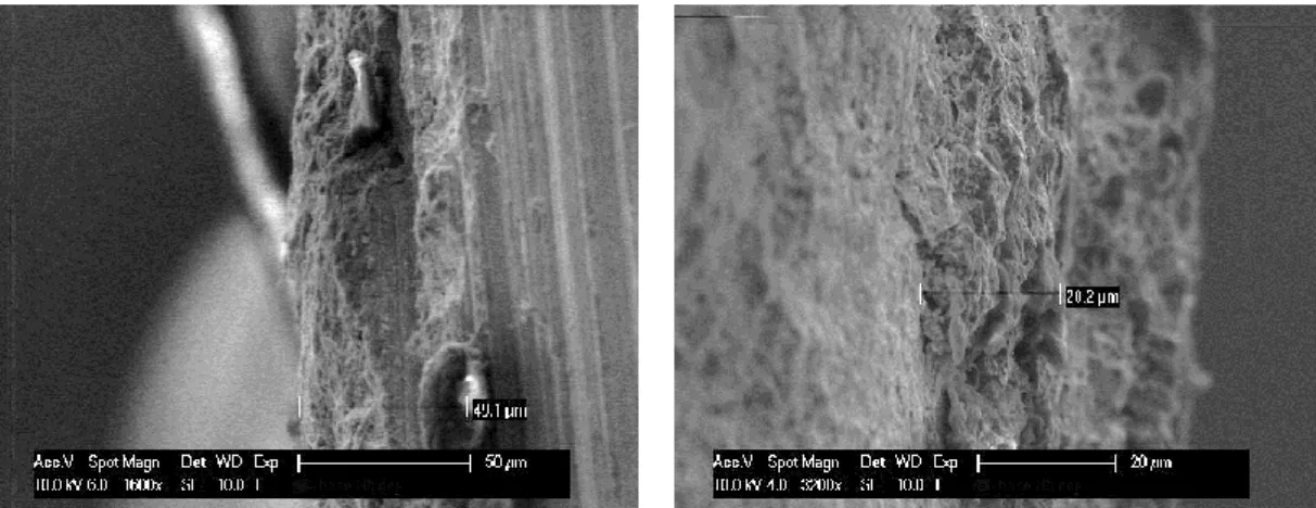
To calculate the thickness of scale some pictures of a raw square bar 50x12 austenitic and martensitic steel were analysed by electron microscope. The thicknesses were measured on both sides of the bar, to clarify the difference in thickness. The high thickness ranging from 20 µm to 50 µm for the austenitic bar and from 70 to 100 μm in the martensitic bar. On the figures, 4.1 and 4.2 are the SEM micrographs.
Figure 4.1: SEM micrographs of the austenitic bar from both side.
Figure 4.2: SEM micrographs of the martensitic bar from both side. 4.1.2. Morphology and microstructural characterization.
After examination of the samples, we saw the different morphology due to the presence of scale and its partial and total removal in the process of blasting and chemical cleaning. The EDX shows a different amount of chromium, nickel and oxygen, depending on the cleaning and passivation. Particularly, the amount of
39
carbon, chromium, nickel and oxygen is maximum in the rough while it decreases in the sandblasted and chemical etched samples.
Figure 4.3: EDX spectroscopy - rough surface - sandblasted - cleaned with standard chemical etching.
Figure 4.4: SEM micrograph rough surface (A), sandblasted (B), leaned with standard chemical etching (C).
C
40
4.2. Characterization of the different steel types.
We characterized the samples with scale from typical steel fabrication by scanning electron microscope to observe differences in the surface morphology (see table 4.1)
Table 4.1: Samples used for the characterization of the scale surface layer.
Type Material Finish Source
Bar AISI 304 raw Bar 8x15
AISL 50 AISI 304 sandblasted Bar 8x15
AU1882/P 51 AISI 303 (doped with sulphur) sandblasted Bar 6x13 VAL 1C AISI 410 (martens.) sandblasted square 50x40
Rod raw rod
Hexagonal bar raw Hexagonal bar
Squared bar raw Squared bar
Wire rod raw Wire rod diam. 21 mm
The SEM micrographs characterize the surface and shows difference in the surface morphology. The micrographs presented in three magnifications (100x, 400x, 1600x), while the surface EDX spectrum shows, which elements compose the outer layers of the sample. The study allowed us to determine that the scale always form a very compact and adherent layer with no visible cracks. Therefore, it is necessary to study a treatment that removes the scale uniformly, avoiding inclusion that mainly attack the underlying steel.
41
Raw bar. On the figures 4.5, 4.6 are presented SEM and EDX analysis of raw steel bar.
Figure 4.5: SEM micrographs of the raw bar, arranged with increasing magnification.
In the layer of scale, also have presented the same elements as in the substrate, such as chromium, nickel, and sulphur. The morphology of the layer is compact and has various structures of different heights. The layer of scale is very adherent to the surface, which appears uniform colour in photos SEM, and the composition remains constant in all areas.
42
43
50 AISL sandblasted. On figures 4.7 and 4.8 are SEM and EDX analysis of steel AISL, sandblasted.
Figure 4.7: SEM micrographs of the bar 50 AISL sandblasted, arranged with increasing magnification.
The sandblasting on the rough bar reveals that the scale follows the roughness profile of the underlying metal: its crystal structure is very similar to steel below, giving rise to a compact and adherent layer. The elemental analysis detects chromium and sulphur with traces of nickel.
44
45
AU 1882 / P 51 doped with sulphur. On figures 4.9 and 4.10 are SEM and EDX analysis of steel AU 1882 / P 51 (doped with sulphur).
Figure 4.9: SEM micrographs of the bar AU 1882 / P 51 (doped with sulphur), arranged with increasing magnification.
The bar, doped with sulphur, presents a series of small inclusions in the steel insert. The layer appears compact, with no apparent porosity. The elemental analysis shows the presence of nickel, silicon and chromium.
46
47
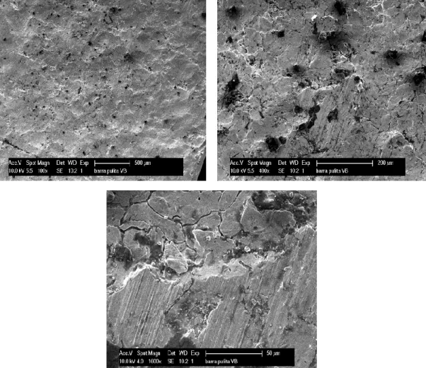
VAL 1C martensitic. On figures 4.11 and 4.12 are SEM and EDX analysis of steel VAL 1C martensitic.
Figure 4.11: SEM micrographs of the bar VAL 1C martensitic, arranged with increasing magnification.
In the sample of VAL 1C martensitic the scale is compact, surface with flakes. The structure develops at different heights, showing roughness and inclusions. The elements identified are the silicon and chromium, both in low percentages.
48
49
Raw rod. On figures 4.13 and 4.14 are presented the SEM and EDX analysis of steel raw rod.
Figure 4.13: SEM micrographs of the raw rod, arranged with increasing magnification. In the raw rod, morphology of the scale shows a compact structure, with the presence of larger particles. From the elemental analysis it is detected the presence of many elements in addition to oxygen and chromium. We observe the presence of aluminium, silicon and manganese, in addition the small traces of sodium and potassium.
50
51
Raw hexagonal rod. On figures 4.15 and 4.15 are presented the SEM and EDX analysis of steel raw hexagonal rod.
Figure 4.15: SEM micrographs of the raw hexagonal rod, arranged with increasing magnification.
The layer of the scale is compact and adherent, with a structure consisting of small surface pores. The structure is less rugged than the raw bar (shown previously). From the elemental analysis, it is detected the presence of silicon, nickel and chromium.
52
53
Raw square bar. On figures 4.17 and 4.18 are presented the SEM and EDX analysis of steel raw square bar.
Figure 4.17: SEM micrographs of the raw square bar, arranged with increasing magnification.
The bar shows a compact surface, formed from crystals of variable size. The elemental analysis detects nickel and sulphur, while aluminium and potassium are barely detectable.
54
55
Raw wire rod. On figures 4.19 and 4.20 are presented the SEM and EDX analysis of steel raw wire rod.
Figure 4.19: SEM micrographs of the raw wire rod, arranged with increasing magnification.
The raw wire rod shows a layer of scale compact and not peeled, with small formations. From the EDAX spectrum, we observe the presence of silicon and chromium, with very little presence of elements coming from the underlying steel.
56
57
4.3. Study of the effectiveness of pre-finish treatment.
4.3.1. Study of the technique of high pressure rinsing.
The treatment of high pressure cleaning uses a water jet pushed at pressures range from 100 to 1000 bar. It is possible to add the water with specific abrasive to increase the effect of the surface.
4.3.1.1. The effect of different pressure (100-800 bar).
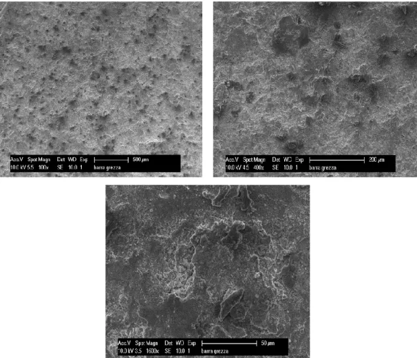
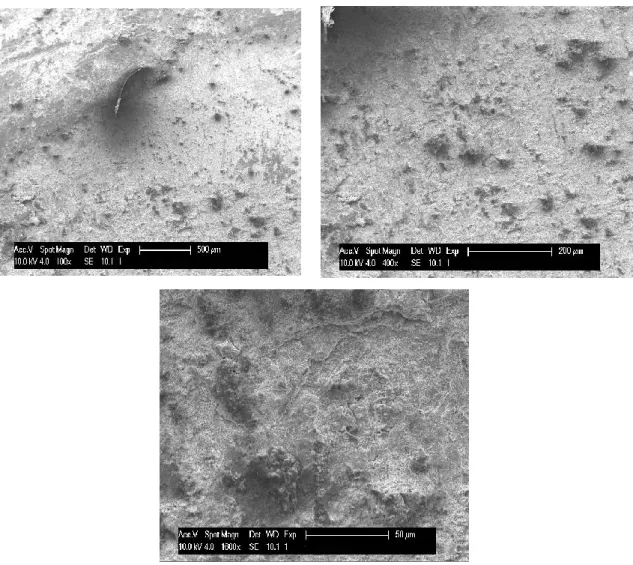
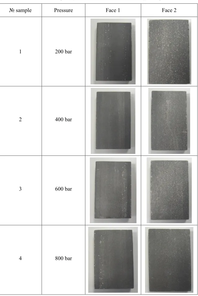
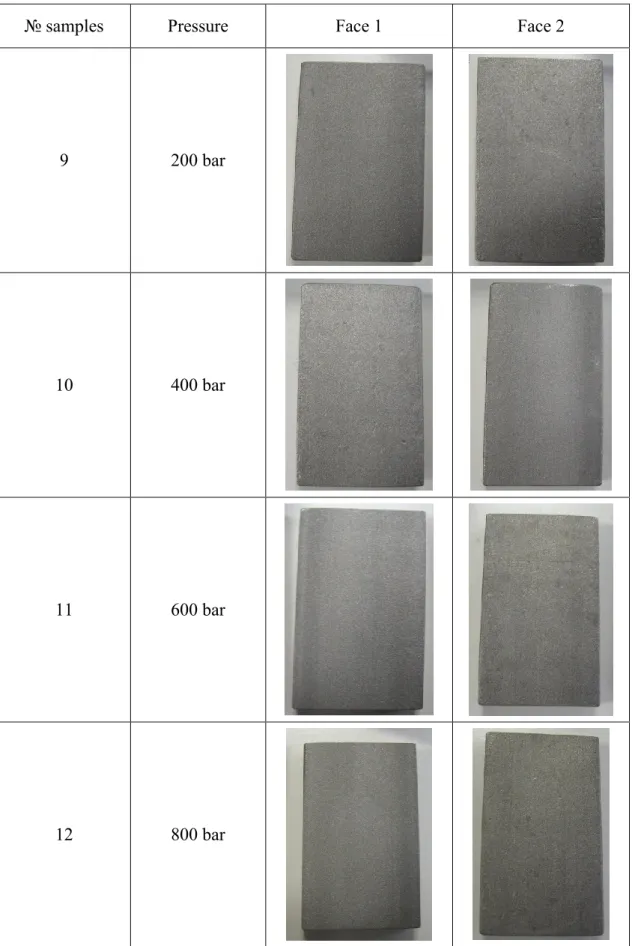
The samples were subjected with HPWR with increasing pressure, to view the effect on the surface. The treatments were performed on pieces sandblasted and raw. The total treatment time is 2 minutes, 1 minute per side. The results are shown in table 4.2. We see that the treatment with water on the raw samples fails to remove various scale from the surface and is not able to obtain a uniform result. The treatment with HPWR on the sandblasted sample makes the surface more uniform and indicating a uniform removal of the scale, but without being able to achieve the appearance of the surface like after the chemical treatment. The HPWR on the sandblasted samples is not able to remove the scale, but only to reduce the thickness. In table 4.2 and 4.3 are shown results of influence different pressure on treatment raw and sandblasted steel bars.
58
Table 4.2: The raw samples after treatment with HWPR at different pressures.
№ sample Pressure Face 1 Face 2
1 200 bar
2 400 bar
3 600 bar
59
Table 4.3: Sandblasted samples after treatment with HPWR at different pressures.
№ samples Pressure Face 1 Face 2
9 200 bar
10 400 bar
11 600 bar
60
4.3.1.2. Study of the influence of the jet angle and different nozzle geometry. By varying, the angle of the jet it is not possible to improve the finish of the treated pieces.
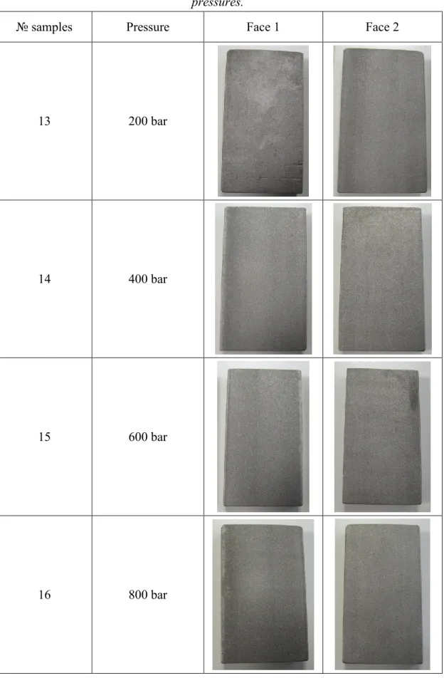
Besides standard nozzle, it has been tested a nozzle blade. The shape of the blade extends the jet’s treatment area but it is less effective than the standard tip. In the following tables 4.4 and 4.5 we can see the results of treatment of raw and sandblasted steel bars.
Table 4.4: The raw samples after HPWR with the nozzle blade at different pressures.
№ samples Pressure Face 1 Face 2
5 200 bar
6 400 bar
7 600 bar
61
Table 4.5: The sandblasted samples after HPWR with nozzle blade at different pressures.
№ samples Pressure Face 1 Face 2
13 200 bar
14 400 bar
15 600 bar
16 800 bar
In conclusions: the treatment of high pressure water rinsing did not remove the scale from the steel surface. In case of raw samples or sandblasted, the different
62
pressures showed the equal appearance of the steel surfaces. The changing of jet angle or nozzle shape did not improve the cleaning.
4.3.1.3. Study of the influence of adding the abrasive.
In HPWR, we added an abrasive to increase the action of the jet. After few minutes of the treatment, we obtained a better finishing on the raw sample than that obtained with industrial sandblasting. There is a visible improvement of the surface of the samples already sandblasted, but not yet comparable to the chemically clean surface. On figures 4.21, 4.22 and 4.23 they are shown comparison of untreated raw and sandblasted steel bars and HPWR with abrasive at 200 and 300 bar.
Figure 4.21: Untreated samples raw and sandblasted.
63
Figure 4.22: Samples after treatment at 200 bar with hot water and sand.
Figure 4.23: Samples after treatment at 300 bar with hot water and river sand. In conclusion: the HPWR with addition of sand as abrasive depends on the water pressure. As we can see, the result after treatment at 300 bar is better, but we did not reach the desirable quality of surface.
sandblasted
raw
64
4.3.2. Study of the effectiveness of “dry ice” -blasting (CO2 -blasting).
The “dry ice” blasting is a form of abrasive blasting, where dry ice, the solid form of carbon dioxide is accelerated in a pressurized air stream and directed at a surface in order to clean it. The sandblasted and raw samples were subjected after “dry ice” blasting. Dry ice was ejected from the compressor with variable pressures, while the other working conditions have remained constant:
• flow dry ice: 45 kg / h; • external temperature: 10 ° C;
• working pressures range from 8 to 14 bar.
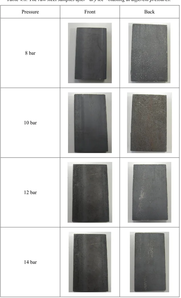
The raw steel bars were photographed from both sides after the treatment (Table 4.6). It can be seen that on the back there is a partial removal of the scale layer, where it is less adherent. The effect, however, does not take place on the overall surface.
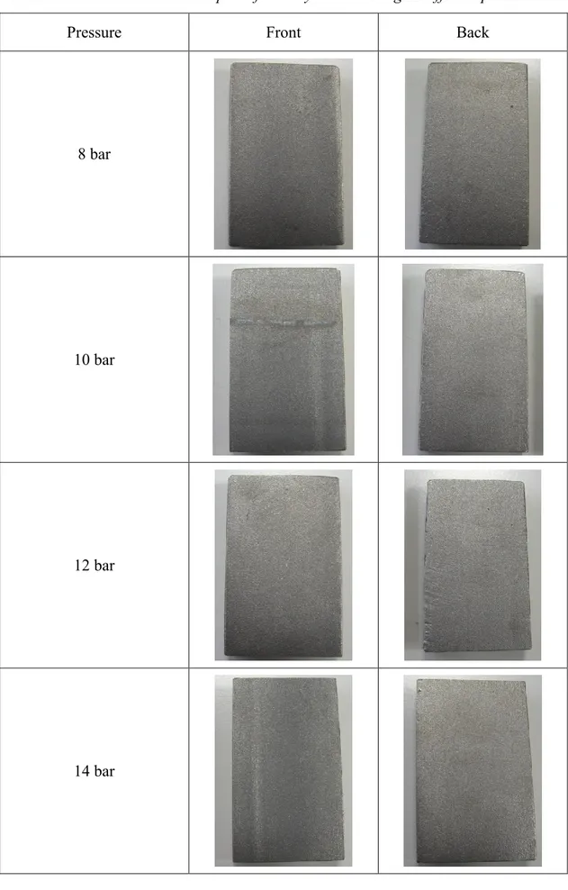
The sandblasted steel samples were photographed from both sides after the treatment (Table 4.7). The effect is less pronounced compared to the raw samples.
In conclusion: The “dry ice”-blasting did not work better than previous treatments. We cannot remove the scale only by sandblasting.
65
Table 4.6: The raw steel samples after “dry ice”-blasting at different pressures.
Pressure Front Back
8 bar
10 bar
12 bar
66
Table 4.7: The sandblasted samples after “dry ice”-blasting at different pressures.
Pressure Front Back
8 bar
10 bar
12 bar
67
4.3.3. Summary of the effectiveness pre-finish treatment.
The all kinds of preliminary finishing: HPWR, wet sandblasting and “dry ice” blasting did not show the ability to remove the scale and demonstrate a satisfactory quality of the surface. In table 4.8, it is presented the summary of results after descaling the raw steel samples and sandblasted steel samples.
Table 4.8: Summary of the pre-treatment study.
Study Sample Observation
Influence of the different pressure
raw steel unsuitable for descaling sandblaster steel unsuitable for descaling
Influence of the nozzle geometry
raw steel unsuitable for descaling sandblasted steel unsuitable for descaling
Influence of the abrasive
raw steel unsuitable for descaling sandblasted steel unsuitable for descaling
Influence of the CO2-blasting
raw steel unsuitable for descaling sandblasted steel unsuitable for descaling