UNIVERSITY OF CATANIA
FACULTY OF ENGINEERING
DEPARTMENT OF ELECTRICAL ELECTRONICSAND COMPUTER ENGINEERING
___________________________________________________________________________________________________
______________________________________________________________________________________________________________________________________________________________________________________________________________________________________________________________________________________________________________________________________________________________________________________________________________________________________________________________
SALVATORE DI MAURO
_______________
Analysis of Solid State Lighting and comparison with
Cold Fluorescent Lamp technology
________________ PHD THESIS ___________ Coordinator
Prof. Eng. L. FORTUNA
Tutor
Prof. Eng. A. RACITI
_______________________________________________________________________________________________________________ ____________________________________________________________________________________________________________________________________________________________________________________________________________________________________________________________________________________________________________________________________________________________________________________________________________________________________________________________
i
CONTENTS
INTRODUCTION ... ....1
1 CHAPTER ONE Definitions of the main parameters that characterize the lamps 1.1 Luminous flux ... 4
1.2 Luminous efficiency, Average lifetime ... 5
1.4 Decay of the luminous flux . ... 5
1.5 Color rendering index, Luminous intensity ... 6
1.7 Color Temperature ... 6
1.8 Maintenance of lamps, Environmental impact ... 7
1 CHAPTER TWO Principles of operation of the main technologies for the production of the lamps 2.1 Historical notes ... 8
2.2 Incandescent lamps ... 9
2.2.1 Operating Principle …….. ……… ... 9
2.2.2 Advantages and disadvantages ……… . 10
2.2.3 Banishment of incandescent lamps from the market .….……….. . 11
2.2.4 Incandescent lamps with halogen ……….11
2.3 Compact fluorescent lamps ... 13
2.3.1 Operating Principle .……….. 14
2.3.2 Main constituent elements ……… 14
2.3.3 Characteristics of the light emitted ………15
2.3.4 Advantages ……… . 15
2.3.5 Disadvantages ……… 15
2.4 LED lamps ... 16
2.4.1 Principle of operation of a LED . ……….. . 16
2.4.2 Colours emitted by a LED diode ………17
2.4.3 Obtain white light from a LED lamp .……….. . 17
2.4.4 Luminous flux-current characteristic ……… 18
2.4.5 Effects of junction temperature on the average life of a LED .……… . 19
2.4.6 Effects of the driving current on the average life of a LED .………… 19
2.4.7 The optics of the LEDs ……… . 20
2.4.8 LED Components .………... 20
2.4.9 Energy balance of a LED .……… . 21
ii
3 CHAPTER THREE Technical and economic comparisons between the main technologies of light bulbs
3.1 Comparison of Luminous Efficiency . ... 22
3.2 Comparison of Average Lifetime ... 22
3.3 Loss of luminous flux ... 23
3.4 Colour rendering index ... 23
3.5 Cost analisys … ... 24
3.6 Analysis of the cost per lumen ... 24
BIBLIOGRAFIA ... Errore. Il segnalibro non è definito.
INDICE
INTRODUCTION ... ....11 CAPITOLO PRIMO Definizioni dei principali parametri che caratterizzano le lampade 1.1 Flusso luminoso ... 4
1.2 Efficienza luminosa, Durata di vita media ... 5
1.4 Decadimento del flusso luminoso ... 5
1.5 Indice di resa cromatica, Intensità luminosa ... 6
1.7 Temperatura di colore ... 6
1.8 Malutenzione delle lampade, Impatto ambientale ... 7
2 CAPITOLO SECONDO Principi di funzionamento delle principali tecnologie di produzione delle lampade 2.1 Cenni storici ... 8
2.2 Le lampade ad incandescenza ... 9
2.2.1 Principio di funzionamento ……… .. 9
2.2.2 Vantaggi e svantaggi ..……….. . 10
2.2.3 Bando dal mercato delle lampade ad incandescenza ……… 10
2.2.4 Lampade ad incandescenza con alogeno ………. . 10
2.3 Lampade fluorescenti compatte ... 12
2.3.1 Principio di funzionamento ……… 13
2.3.2 Principali lementi costituenti ……… . 13
iii
2.3.4 Vantaggi ……… . 13
3 CAPITOLO TERZO: L’ IMPRESA FAMILIARE Errore. Il segnalibro non è
definito.
3.1 I presupposti soggettivi ... Errore. Il segnalibro non è definito. 3.2 La disciplina fiscale ... Errore. Il segnalibro non è definito.
3.3 I punti di forza e di debolezza delle imprese familiariErrore. Il segnalibro non è definito. 3.4 La successione nell’impresa familiare ... Errore. Il segnalibro non è definito.
3.5 Le tipologie di successione ... Errore. Il segnalibro non è definito. 3.5.1 Successione in assenza di eredi
Errore. Il segnalibro non è definito.
3.5.2 Successione in caso di eventi traumatici
Errore. Il segnalibro non è definito.
3.5.3 Successione imprenditoriale
Errore. Il segnalibro non è definito.
3.6 Le operazioni di finanza straordinaria ... Errore. Il segnalibro non è definito. 3.6.1 Lo scorporo
Errore. Il segnalibro non è definito.
3.6.2 Il Leveradge
Errore. Il segnalibro non è definito.
3.6.3 La quotazione in borsa
Errore. Il segnalibro non è definito.
1
INTRODUCTION
For many years research in the field of lighting technology is directed toward conversion of electrical energy into visible light to ensure greater energy savings. More recent research has addressed the production of LED lamps, by using light emitting diodes as an alternative to compact fluorescent lamps. LED lamps offer a different technology for the direct conversion of the electrical energy into visible light and are about to introduce a revolution in lighting systems, similar to that produced by incandescent lamp over two centuries ago
The use of electricity for home lighting represents a significant proportion (approximately 13%) of the total electricity consumed. It is estimated that the development of using of LED domestic lamps contribute to drastically reduce the consumption of energy, which, with an efficient electronic, it could limit the global energy consumption for lighting to about 20% compared to that of incandescent lamps and nowadays it is banned within the most developed nations. The Italian national energy plan, in terms of energy saving, provides standards that promote and encourage, in accordance with the Energy Policy of the European Economic Community, the reduction of energy consumption in the production and use of artefacts. The purchase of high-efficiency lamps is included in interventions aimed at improving the use of energy in homes. From here the importance that the consumption of electricity for lighting.
Is evident as more and more attention is directed to realization of efficient lamps from the point of view of energy consumption, and cost-effective under the different profiles of production, disposal of the exhausted products, environmental protection, associated risks of pollution, toxicity of materials, etc..
At the time the technology of light bulbs is essentially based on two main types of products: the cold cathode fluorescent lamp (in technical jargon we use the acronym CFL, cold fluorescent lamp), and the solid-state lamp (or SSL) based on the use of the emitting diodes (light emitting diode, or LED).
The industrial interest is now directed towards the development and production of LED lamps for their remarkable features: the high energy saving,
2
control brightness and color and a long operating life. It is clear that the interests of consumers and technicians is directed to the understanding of the advantages and disadvantages of this new technology generation of light. From this scenario emerges the usefulness of the analysis and comparison of LED lamps and existing technologies, and in particular with compact fluorescent lamps. Both the CFL that LED lamps, as opposed to the now disused incandescent lamp, which accounted for the power grid a linear load (with sinusoidal voltage absorbs sinusoidal current), are, for the power grid, a highly non-linear load and introduce a high content of harmonic current distortion.
In this thesis work is carried out a detailed analysis of LED technology, and are provided principles of design of a power supply circuit of an LED lamp. It also developed a comparison between the two different technologies, investigating in particular on the main lighting parameters of the light sources, identifying the main terms of comparison, and by tracing of technical and economic comparisons between the two technologies. Finally, it is analyzed the harmonic content of the current absorbed from the mains supply by these two types of lamps, through laboratory measurements and a detailed analysis, determining the different quantities that have importance with reference to the harmonic distortion produced by both lamps.
The first chapter lists the main technical and lighting parameters the of a light source that will be used to characterize the various types of lamps: luminous flux, luminous efficacy, average lifetime, decay of luminous flux, color rendering index, luminous intensity, color temperature. The second chapter describes the operating principles of the main technologies for the production of the lamps; from incandescent lamps (in legal prescription in major developed countries) up to the recent LED bulbs, and are also discussed advantages and disadvantages of each of them.
The third chapter presents the technical and economic comparisons between various technologies of light bulbs and the main LED lamps now present on the market, in order to clarify the technical and economic motivations that are the basis of technological breakthrough that will affect the world of lighting.
3
In the fourth chapter, is designed and then simulated, both open-loop that closed-loop, the power supply circuit of an LED lamp to light "hot" high flux (850 lumen), and are obtained some of the most important parameters electric and lighting that characterize it.
Finally, in the fifth chapter are referred to the definitions of the various electrical quantities that are of interest (instantaneous power, active and reactive power, power factor etc.., As well as accepted in the technical community), in agreement with the IEEE Standard 1459-2010 [1 ]. Two different lamps, a CFL and a LED, are investigated with a series of measures to the rated voltage of 220V and for values lower or higher than this value. The main technical features are detected by analyzing the harmonic content of the input current and the characteristics of the power absorbed by the network, providing a report on a comparison of the various technical parameters of the two different technologies.
4
1
DEFINITIONS OF THE MAIN PARAMETERS THAT
CHARACTERIZE THE LAMPS
Are Identified and listed the main technical and lighting parameters of a light source that will be used to characterize the various types of lamps: luminous flux; luminous efficiency, average lifetime, decay of the luminous flux, color rendering index, luminous intensity, temperature colour. Is given a definition of these parameters.
1.1 Luminous flux
The luminous flux (Φ) is defined as the amount of light energy emitted in unit time multiplied by the coefficient of visibility. The unit of measurement is the lumen (lm). At any device able to transform the absorbed energy into light energy, that is in electromagnetic radiations contained in the visible spectral region, is associated with a luminous flux. In the calculation of the luminous flux, generated by a source, it takes into account the sensitivity of the human eye to different wavelengths of radiation.
As shown in Fig 1, the spectral sensitivity of the human eye varies as a function of the wavelength of the radiation, in particular the maximum sensitivity of the eye is that relative to the wavelength of 550 nm, and as we moves away from this value, it diminishes to zero near λ ≈ 380 nm and λ ≈ 780 nm (lower threshold and upper threshold of the visible). The luminous flux is the definite integral between the two limits of the visible (λ = 380 nm and λ = 780 nm) of the product of the power of monochromatic radiation emitted pλ and the factor of visibility relative V (λ) for a constant K = 683, which converts Watt in lumens:
Φ=K 780
5
Fig.1.1 Sensitivity of the human eye to different wavelength
1.2 Luminous efficiency
The luminous efficacy, expressed in lumen/watt, is defined as the ratio of the luminous flux emitted by a primary source and the electrical power absorbed by it. It is one of the most important parameters and refers to the "efficiency" of transduction, thus allows to compare the energy consumption of lamps of different technologies.
1.3 Average lifetime
It is defined as the number of hours of operation after which 50 % of the lamps of a representative batch, operating in the established conditions, turns off. The average lifetime is measured in hours (h) . With economic life refers to the time in hours after which the flux emitted by a lot of lamps has decreased by 30% relative to nominal value. There are many factors that affect the operational life of a lamp and are related to the unfavorable conditions of operation, as the working temperature , the number and frequency of the ignitions , the mechanical stresses.
1.4 Decay of the luminous flux
The decay of the luminous flux as a function of time is a phenomenon that involves the lamps. It for the traditional lamps is manifested by a blackening of the glass that incorporates the body light emitter or with the degradation of the substances (fluorescent powders, filling gas, etc..) Through which one has the emission of light and is usually accompanied by a greater absorption power, and then by a decrease of the luminous efficiency.
6
1.5 Color rendering index
This parameter, which is characterized by different definitions on which there is no consensus (CRI, Ra, etc..), is a number which quantifies on a scale from 0 to 100 the ability of a light source to render faithfully the true colors. The quantification is done by comparison with a reference source and evaluate the alteration of the color of the illuminated surfaces as perceived in the two conditions. The sample source is the incandescent lamp used in a very precise temperature. The color rendering index Ra is divided into six ranges of values as shown in Table I.
Table I Classification of color rendering index Classification Color rendering index Grade 1A - OPTIMAL 90 < Ra < 100
Grade 1B - VERY GOOD
BUBBUBUONOBUONO 80 < Ra < 89 Grade 2A - GOOD 70 < Ra < 79 Grade 2B - DISCREET 60 < Ra < 69 Grade 3 - SUFFICIENT 40 < Ra < 59 Grade 4 - POOR Ra < 40 1.6 Luminous intensity
The Luminous intensity (I) s a photometric vector defined as the ratio between the luminous flux infinitesimal (dΦ) issued within the infinitesimal solid angle (dΩ) and the same solid angle:
I=
d
d (2)
The luminous intensity expresses the concentration of light in a specific direction. The unit of measure in the SI is the candela (cd), the fundamental unit of photometry.
1.7 Colour temperature
The color temperature of a lamp is the temperature in Kelvin degrees, to which must be brought to a black body so that emits a radiation of the same color. In physics, a black body is an object that absorbs all incident electromagnetic
7
radiation. At higher color temperatures correspond cold shades of light, and contrary to low color temperatures correspond warm tone of light. The warm hues (<3800 K) tend to yellow in color, the cool shades (> 5000 K) have shades of blue, shades neutral (3800 K <T <5000 K) are whitish.
Below are other factors on the basis of which we can compare light sources.
1.8 Maintenance of lamps
With maintenance are indicated all measures to maintain or restore an electrical system in a state where it can perform the required function, respecting the parameters and design conditions
1.9 Environmental impact
The presence, among the components of the bulbs, of special substances and harmful as mercury and lead, can cause problems for the health of users. The manufacturers of lamps are engaged to reduce the content, but their presence can not be eliminated in order to function effectively. It therefore remains the task of controlling, with a conscious disposal, the risks associated with their presence.
8
2
PRINCIPLES OF OPERATION OF THE MAIN
TECHNOLOGIES FOR THE PRODUCTION OF THE LAMPS
FROM THE TRADITIONAL LAMPS TO THE LED LAMPS2.1 Historical notes
The latest generation of LED can be counted among the most promising light sources in a wide range of applications. Its rootedness will determine major changes in the management of lighting. In the first place, what changes is the way to generate light, that is to transform the radiation energy to get that the human system eye/brain is able to perceive as light. For thousands of years, the only way to produce light is based on the combustion of substances of various kinds. In 1879 he had extraordinary success the invention of the incandescent lamp by Thomas Alva Edison.
The filament lamp is an artificial light source, operating on the principle of irradiation of photons generated by the overheating of a metallic element. It then presents the problem of the development of heat, which makes short the life of each light source. At the beginning of the 900 you start to work on the electrical charges flowing in masses consisting of gaseous substances. In 1938 was born the linear fluorescent discharge lamp that works thanks to the fast and cyclic recurrence of small electric shocks in gaseous atmospheres, with the result of having less heat produced in the process and a strong growth in the value of efficiency: more light, less electrical power consumption.
In 1907, Henry Joseph Round discovers the physical effect of the electro-luminescence, but this discovery is initially neglected until 1962, year in which it is presented the first red light emitting diode, type GaAsP semiconductor. In 1971, it was the turn of the LEDs of other colors: green, orange, yellow.
9
TRADITIONAL LAMPS
2.2 Incandescent lamps
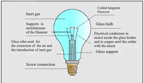
Traditional incandescent lamps, was produced since 120 years, and still using today. The main elements that make up these lamps are: the filament, the gas filling, the ampoule and attack.
Fig 2.1 Incandescent lamp
For the manufacture of the filaments is used the tungsten. This metal, made to pass through special dies, is reduced to diameters of less than ten thousandths of a millimeter. The bulbs of incandescent lamps are generally made of transparent glass joint. The attacks are commonly type ferrule marked with the letter E (Edison) followed by the measurement of the diameter in millimeters. The lamps of power less than 300W are equipped with a screw attack type E27
2.2.1 Principle of operation
The heart of these lamps is the tungsten filament. This metal has a very high melting point (3400° C) and evaporates at temperatures also very high. When the lamp is connected to the power supply, flows through the filament an electric current, by heating to incandescence, so that this can emit electromagnetic waves belonging also to the spectrum of the visible. Until the filament does not exceed 1000° C, there is no emission within the visible spectrum; at 2000 ° C for only
10
3% of the energy supplied is transformed into light energy. The luminous efficiency of these lamps increases with the temperature of the filament, and therefore with the increase of the current flowing through it; but compared with the increase in temperature decreases the average life of the lamp. The overall power of the incandescent lamp is dissipated for 83% in infrared radiation, 12% into heat, while only 5% is used as a useful light radiation; from here if infers the low light efficiency (greater share of energy is dissipated as heat).
Fig. 2.2 Schematic diagram of incandescent lamps
2.2.2 Advantages and disadvantages The advantages are:
Colour rendering index equal to 100; Zero start-up time;
Low purchase cost; Small footprint;
Supports in molybdenum of the filament
Inert gas
Glass tube used for the extraction of the air and the introduction of inert gas
Screw connection Coiled tungsten filament Glass bulb Glass support Electrical conductors in nickel inside the glass holder and in copper until the solder with the attack
11
The disadvantages are represented by a low luminous efficiency (average value of 15 lm/W), the short duration of life (the average lifetime is, in conditions of normal power supply, generally 1000 hours), high heat emission, and high
consumption. .
2.2.3 Banishment of incandescent lamps from the market
Incandescent lamps, for their low efficiency, have been banned from the market. In March 2009 the European Commission published in the Official Gazette 244/2009/CE o 244/2009/CE on Regulation which provides for the gradual banishment from the market [
5
]. From 1 September 2011 it is no longer possible to market incandescent lamps with a power greater than or equal to sixty watts. And since 1 September 2012, is no longer possible to market incandescent lamps of any power.2.2.4 Incandescent lamps with halogen
The reasons for which the traditional incandescent lamps are characterized by luminous efficiency and lifetime of very low value are related to:
The rapid evaporation of the tungsten filament from which it is composed The progressive blackening of the inner wall of the interrupter
in order to effectively counter these effects, around 1950, were introduced the first incandescent lamps manufactured on the basis of the so-called "regeneration cycle of the filament”, commonly referred to as halogen lamps. This cycle which is based on the introduction, inside lamps, (of) a small amount of halogen (bromine or iodine) is divided into the following phases::
12
The vapors of tungsten which are formed due to the sublimation (direct transition of a substance from the solid state to the gaseous state without passing through the liquid state) of the filament brought to incandescence, it move toward the inner wall of the lamp, the temperature of which is of about 700° C. At this temperature the vapors of tungsten chemically react with the halogen present within the lamp itself, giving rise to the formation of a halide of tungsten.
The vapors of tungsten halide which are thus formed tend to move to the filament. The very high temperature of the latter (about 2500 ° C) triggers the reverse reaction and the dissociation of tungsten halide in halogen and tungsten metal. The tungsten that is formed is deposited on the filament and tends to partially reconstruct the integrity while freeing halogen and ensures the continuation of the cycle.
So that the chemical combination between tungsten atoms and halogen can take place, it is necessary that the temperature of the filament is not below 2000 ° C. It is also important to dose with precision the amount of halogen introduced into the bulb, Indeed, if this amount is in excess there is a loss of light for absorption by halogen, if this quantity is at fault it has a premature stopping of the regeneration cycle of the filament.
Because the bulb, to allow the chemical reaction between iodine and tungsten, must have a temperature not lower than 250 ° C, for this is used a special high-strength glass, quartz. The higher temperature of the filament produces light more white than that emitted by the traditional incandescent lamps, while precisely the color temperature of the light emitted by the latter is about 2800 K, the light emitted by the halogen lamps is about 3000 K.
13
COMPACT FLUORESCENT LAMPS
2.3 Compact Fluorescent Lamps
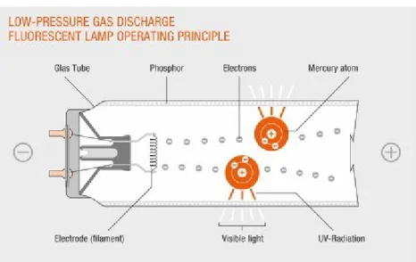
Compact fluorescent lamps belong to the family of light sources to gas discharge in which the emission of visible light is indirect, that is not directly emitted by the ionized gas, but from a fluorescent material.
.
Fig 2.3 Compact Fluorescent Lamps
.
The fluorescence is the property of a material to emit light when it is excited by ultraviolet radiation. Fluorescent lamps are characterized by luminous efficiency and lifetime average (6,000 ÷ 15,000 hours) significantly higher than incandescent lamps; they are, among all light sources, much more those used for the interior lighting.
14
Compact fluorescent lamps, or CFL (compact fluorescent lamp), designed to concentrate the emission of light in a small volume, are constituted by a glass tube of shape such as to have little space (U multiple, or propeller) inside which there is empty. Then a noble gas (argon, xenon, neon, or krypton) is introduced at low pressure and also a small amount of liquid mercury, which partially evaporates mingled with the noble gas. The inner surface of the tube is coated with a fluorescent material, by the appearance of a white powder. In each of the two ends of the tube an electrode is coated with substances to emit, in certain conditions, a significant amount of electrons, the presence of which promotes the initiation of the discharge.
2.3.1 Operating Principle
Connecting a lamp to a power network by a power supply, a part of atoms of mercury, contained in the tube, is split into ions and electrons are emitted. These latter collide against other mercury atoms not yet ionized freeing other electrons which in part back to recombine; losing energy and emitting ultraviolet radiation not visible , especially of a wavelength of 254 nm.
The fluorescent material covering the tube, hit by such radiation, in turn emits radiation of longer wavelength (lower frequency), belonging to the visible range. The frequency and the energy of visible light are lower than the ultraviolet light and so the transformation produced involves a loss of energy in the form of heat.
2.3.2 Main Constituent Elements
The tube is made, normally, of glass containing soda and lime. The electrodes, generally are constituted by a tungsten filament covered by a " mixture emitter " (consisting of oxides of barium, strontium and calcium). calcio). They perform the dual function to furnish electrical power inside of the discharge tube and to provide the electrons necessary to trigger and maintain of the same charge. Attack is type E27.
15
2.3.3 Characteristics of Light emitted
The most important factor that determines the characteristics of the light emitted by these lamps is the composition of the powders used to coat the inner wall of the tube that convert the ultraviolet radiation produced by the atoms of mercury into visible light. Generally, different types of fluorescent powders are used : the tri-phosphor, or pentafosforo are the standard but, now, they are in the process of elimination. The tri-phosphor powders (ternary mixtures consisting of three halophosphate), determine a peak of radiation in correspondence of three well-defined wavelengths: blue, green and red. The lamps with powders of this type are characterized by high luminous efficiency (about 90 lm / W) and a color rendering index between 80 and 85. The powders pentafosforo, finally, are constituted by a mixture of rare earths. The lamps emit light characterized by very high color rendering index (equal to or greater than 95) but their efficiency is lower than the powders of the triphosphorous type (about 65 lm / W).
2.3.4 Advantages
1. High luminous efficiency
2. Content consumption of electric energy
3. Ease of interchangeability with incandescent lamps 4. Small footprint
5. Good average lifetime (6000÷15000 ore) 6. Acceptable color rendering index (75÷90) 7. Different shades of light (2700 K ÷ 5400 K) 2.3.5 Disadvantages
1. Higher costs of the incandescent lamps (average cost 8€) 2. Decay in time of the luminous flux
16
LED LAMPS
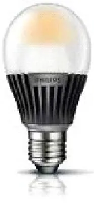
Fig 2.5 LED lamp
2.4.1 Operating principle of the LED diode
Figure 2.6 Basic diagram of a LED diode
The LED diode is a particular p-n junction composed by a thin layer of doped semiconductor material. When the LED is subjected to a direct voltage, in the junction area the electrons recombine with holes of the valence band, going to lower energy state, and giving energy that is released in the form of radiation or photon. Due to the reduced thickness of the semiconductor, a reasonable number of these photons is emitted as light. The exact choice of the semiconductor determines the wavelength of peak emission of photons and therefore the color of light. Unlike of incandescent lamps which emit a continuous spectrum, an LED emits monochromatic light of a particular color.
17
2.4.2 Colors emitted by a LED diode
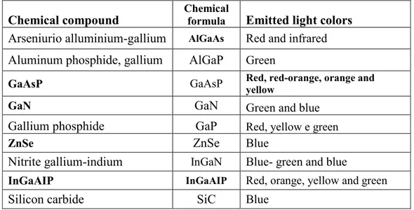
The LED technology shows special characteristics compared with conventional lamps used so far. Innovative feature compared to traditional light sources is the ability to create any kind of color tonalities. The color of the emitted light depends on the type of material that constitutes the diode and the type of impurities that are present. The most common types of LED are listed in Table II.
Table II. Main colors obtained with LED diodes
Chemical compound Chemical formula Emitted light colors Arseniurio alluminium-gallium AlGaAs Red and infrared Aluminum phosphide, gallium AlGaP Green
GaAsP GaAsP Red, red-orange, orange and yellow
GaN GaN Green and blue
Gallium phosphide GaP Red, yellow e green
ZnSe ZnSe Blue
Nitrite gallium-indium InGaN Blue- green and blue
InGaAIP InGaAIP Red, orange, yellow and green
Silicon carbide SiC Blue
The chemical compounds used more frequentlyare the Gallium arsenide (GaAs), the Gallium phosphide (GaP), the Gallium arsenide phosphide (GaAsP), the Silicon carbide (SiC), and the Gallium nitride and Indium (GaInN).
2.4.3 Obtain white light from a LED lamp
Since all the LED diodes emit light having a narrow-band spectrum, in order to obtain white light is necessary to mix the radiation. We adopt various ways for the synthesis:
1. Heterochromatic light (white) obtained with additive synthesis of three primary colors (RGB, red-green-blue). It is possible to embed, within a single light source, three LED capable of generating light of the colors red, green and blue, that is the three primary colors of additive synthesis. By
18
mixing and adjusting individually these colors by using lenses able to merge the three luminous fluxes, we get different tonality of white light; 2. Heterochromatic light (white) obtained with additive synthesis of
complementary colors (blue-yellow). Phosphors based substances are used in the protective covering of the chip;
3. Heterochromatic light (white) obtained with conversion of ultraviolet radiation into visible one. Phosphors are used.
2.4.4 Luminous flux-current characteristic
The performance of the LED lamps depend on a number of physical parameters that influence each other; these parameters fix clear differences with other light sources. Each LED is designed to generate a luminous flux to a certain value of current (driving current) and junction temperature, Figure 2.7. The 15% of the electrical energy is transformed into light, whereas the remaining 85% is lost as heat. The constant level of the current is ensured by the power supply circuit.
Fig. 2.7 Luminous flux of an LED as a function of current at a given temperature
19
2.4.5 Effects of junction temperature on the average life of a LED
An important parameter that defines the photometric and colorimetric performance of a LED is the junction temperature. In Figure 2.8 is shown how the luminous decay varies as a function of time of operation at different junction temperatures for a driving current of 350 mA. Note that the higher the junction temperature and the shorter the average life of the LED. One understands how important, it is to get the maximum performance, that the junction temperature is not high during operation.
Fig. 2.8. Luminous decay of an LED as a function of temperature junction for a current of 350 mA
2.4.6 Effects of the driving current on the average life of a LED
Also the value of the current affects the average life span. Increasing the current produces a larger luminous flux, as shown in Figure 2.7, but at the expense of durability and light efficiency; grows then the decay of the life of the semiconductor. To reduce the junction temperature, using a heat sink, that is a thermo-mechanical system, characterized by the thermal resistance parameter that acts as an interface between the heat source and the external environment.
20
2.4.7 The optics of the LEDs
The LEDs are born with a view, called micro-optics primary protective, which incorporates the chip itself so as to disseminate and refract the light that is emitted in all directions in a manner not determinable.
Then there are the secondary optics, which are aggregated to the LEDs and components that work in synergy with the optical primaries in finding the best luminous efficiency and better performance.
2.4.8 LED Components
Fig. 2.9 LED Components
In Figure 2.9 are shown the various components of an LED. Each component introduces yield losses in the system. From here it appears clear the importance of choosing appropriate materials, to optimize every part of the project of the Lamp, in order to increase the efficiency of light extracted from a LED.
Mechanical protection system
di protezione meccanico Secondary lens for directing the beam of light
Support LED
heatsink Power Supply
21
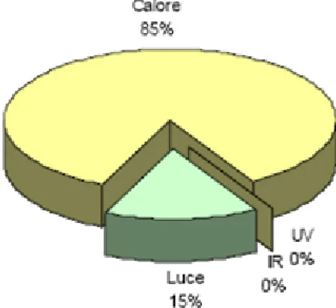
2.4.9 Energy balance of a LED
Figure below shows the distribution of energy for a light emitting diode. Note the absence stated by the manufacturers of infrared and ultraviolet radiation. Note also that 15% of the absorbed energy is converted into light, while the remaining 85% is lost in the form of heat.
Fig. 2.10 Distribution of energy of a LED
2.4.10 Features of LED lamps
The LED diode in itself brings a series of special features and performance that determine the advantages of its use in lighting applications:
1. Very long average life (25000/50000 ore). The life cycle of a product LED is about 3/4 times higher than the best fluorescent lamps;
2. High luminous efficiency (40÷60lm/W);
3. Control of brightness and color (the emitted light is proportional to the bias current of the LED);
4. Negligible emission of UV radiation;
5. Maintenance of luminous efficiency over time; 6. Turning On and Instant Off;
7. Total absence of toxic substances (as mercury); 8. Robustness to shock and vibration;
22
3
TECHNICAL ECONOMIC COMPARISONS BETWEEN THE
MAIN TECHNOLOGIES OF BULBS LIGHT
Fig. 3.1 LED and CFL lamps
Introduction
The characteristics of comparison, as mentioned, are mainly based on both technical and economic performance that the new LED technology can provide to the advantage or disadvantage compared to traditional sources.
3.1 Luminous efficiency comparison
The main parameter to be considered for the evaluation of the energy saving is the luminous efficiency. LED technology, unlike any other light sources, has only dispersive emission of heat; therefore it is not affected by issues related to the ultraviolet and infrared radiations. It is clear, from the comparison between CFL and LED lamps, that the luminous efficiency of the two technologies reaches very close values (50-60 lumens/watt); moreover, the present efficiency of an LED device could be increased up to 100 lumens/watts, but this would lead to a lifetime reduction.
3.2 Average Lifetime Comparison
With regard to the average lifetime, the LED lamps are the best. From the data in possession we realize immediately how this technology has not rivals from this point of view; in fact, while the lifetime of the Master LED lamp is about 25000
23
hours, that of the compact fluorescent lamps is very lower, around 10000 hours of average working operation, Table III.
Table III. Characteristics of three different types of lamps
Compact
CFL
LED
retrofit
Model Master PL
8W/827 Genie ESaver 8W/827 Master Ledbulb 7W A60 Average lifetime [h] 15000 (60% flux)
5000 (85% flux)
8000 (65% flux)
5000 (75% flux) 25000
Luminous flux 400 lumen 420 lumen 400 lumen
Power [w] 8 8 7 Luminous efficiency [lm/w] 50 53 55 Colour temp. [k] 2700 2700 2700 Colour rendering index 82 82 80 Cost [€] 10 6 35 Adjustable No No Si
3.3 Decay of Luminous flux
If we analyze the luminous flux decay after a time equal to the average lifetime, the experimental data shows results of 38% for CFL and 30% for LED. The LED technology has the peculiarity of presenting only a small percentage of luminous decay (2-5%) to around 10000 hours of working operation.
3.4 Color Rendering Index
In terms of color rendering index, both for LED and CFL lamps, the values are around 80, since the operating principle of the LED diode is similar to that of any of the discharge lamp, that is the discrete photons emission.
24
3.5 Costs analysis
The economic comparison is performed by evaluating the average annual cost of each lamp, taking into account the average lifetime and the costs of purchase, and by assuming an average daily use of 5 hours.
It is obvious that nowadays compact fluorescent lamps have the lowest average annual cost. In particular, the models reported in Table IV have a cost of approximately € 1.3; LED lamps have a double average annual cost.
CFL integrata
LED retrofitModel Master PL 8W/827 Genie ESaver
8W/827
Master Ledbulb 7W A60
Average lifetime 8,22 4.38 12,7
Purchase cost [€] 3 6 35
Average annual cost[€] 1,34 1,37 2,75
An economic comparison regarding the annual energy consumption of the two lamp types, since the values of luminous efficiency are very close, provide very similar results.
3.6 Analysis of the cost per lumen
It is interesting to analyze the cost per lumen provided by the two types of lamps as a function of time, defined as the ratio between the average annual cost of the lamp and the produced lumens; since the luminous decay shown with the hours of operation is different for the two technologies. The compact fluorescent lamp has a luminous flux after 8000 hours of working operation of about 35%; for the LED lamp we can say, with good approximation, that after the same number of hours the luminous flux emitted is almost the nominal one.
Table IV. Economic data of three different types of lamps
25
The average lifetime of the CFL lamps is of 10000 hours, whereas that of the LED lamps is of 25000 hours. Assuming an annual working operation of 2000 hours, the results are extrapolated for four years of use.
For the first year the compact fluorescent lamp has a cost of 0.0038 €/lm, whereas the LED lamp has a cost of 0.007 €/lm, which is about double. For the second year of use, the CFL cost becomes of 0.0042 €/lm, whereas the LED lamp has an unchanged cost, 0.007 €/lm. For the next two years the CFL has an even greater cost, 0.0057 €/lm, whereas the LED has a cost of 0.0072 €/lm, slightly higher than the first two years. This suggests that during the first year of use the cost per lumen of the CFL lamp is about half of that of the LED. In the following years, the difference is less marked due to the luminous decay presented by the CFL.
26
4
POWER CIRCUITS FOR LED LAMPS
4.1 M
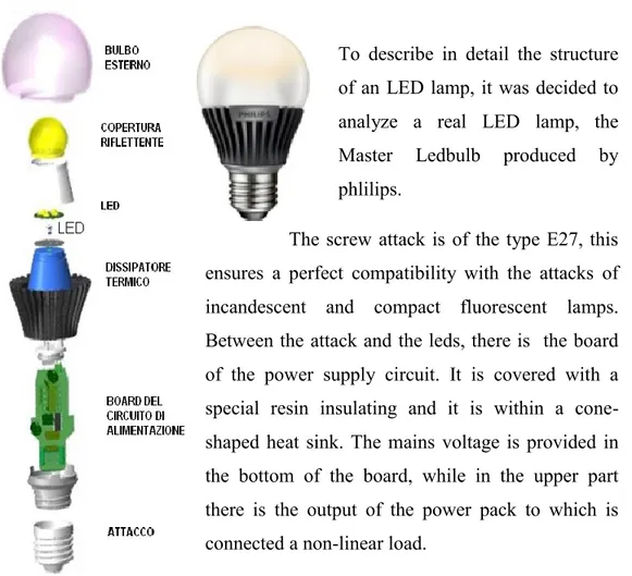
ain components of a LED lamp
To describe in detail the structure of an LED lamp, it was decided to analyze a real LED lamp, the Master Ledbulb produced by phlilips.
The screw attack is of the type E27, this ensures a perfect compatibility with the attacks of incandescent and compact fluorescent lamps. Between the attack and the leds, there is the board of the power supply circuit. It is covered with a special resin insulating and it is within a cone-shaped heat sink. The mains voltage is provided in the bottom of the board, while in the upper part there is the output of the power pack to which is connected a non-linear load.
Figura 4.1: Lampada a Led
The latter consists of 5 diodes Luxeon Rebel at blue light arranged in series. The LEDs are in turn inserted inside a bulb reflective coated with substances phosphors based in order to obtain white light by additive synthesis of complementary colors (blue-yellow). An outer bulb completes the structure of the lamp
27
4.2
Power Converters for LED lamps
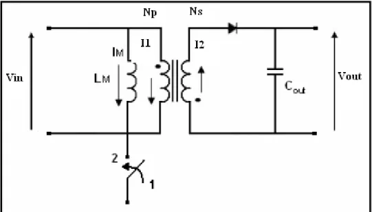
At the entrance of the dc-dc converters in general there is an unregulated dc voltage obtained by rectifying the mains voltage. A switching dc-dc converter is then used to convert the voltage not adjusted to a value of the voltage controlled to the desired level. The flyback belongs to the category of dc-dc converters with isolation between input and output. The insulation is achieved by the use of a transformer, which works at switching frequency; this ensures a significant reduction in terms of size, weight and cost compared to processors that work at line frequency.
Figura 4.4: Modello circuitale del flyback
The transformer acts as an inductance with two windings: in the time ton (switch
closed) it stores energy in the magnetic field and then transfer it in the time toff..
When the switch is closed (ton), a voltage is induced in the secondary. It doesn't
produce passage of current for the presence of the diode. The current and the energy to the load are therefore provided by the output capacitor Cout.
When the switch opens, the voltage at secondary reverses its polarity, the diode forward biased and the energy stored in the transformer is transferred to the load.
28
5
TECHNICAL AND HARMONIC ANALYSIS OF LED LAMPS
AND CFL
Introduction
In this chapter, are first called up the definitions of the various electrical quantities that are of interest (instantaneous power, active and reactive power, power factor etc.., as well as accepted in the technical community), in agreement with the IEEE Standard 1459-2010 [1]. Two different lamps, CFLs and LEDs, are investigated with a series of measures to the rated voltage of 220V, to detect the main technical features. For this purpose the means of investigation used is a common digital storage oscilloscope, supplied in any electronics laboratory. The lamps that are investigated: a CFL lamp (A) 15W nominal and a LED lamp (B) 7W nominal. The measurements are carried out at the nominal voltage of 220V and for values lower or higher than this value. Is detected in all conditions the harmonic content.
5.1
HARMONIC ANALYSIS OF THE POWER ABSORBED BY
THE LAMPS
In stationary conditions, with distorted waveforms of voltage and current (not sinusoidal), the Fourier analysis enables us to derive the component at the fundamental frequency and the harmonic components of higher order h. Indicating with V and I, Vh and Ih the root mean square value of voltages and
currents, respectively, for the fundamental and harmonic h, we obtain:
H
v
v
v
1 ei
i
1i
H)
sin(
2
1 1 1V
t
v
(2)29
i
12
I
1sin(
t
1)
(3)v
H2
sin(
)
1 h h ht
h
V
(4)2
Hi
sin(
)
1 h h ht
h
I
(5) 2V
=T
1
t Tv
dt
t 2 =V
12V
22
V
h2=V
12V
H2 (6) 2I
=T
1
t Tv
dt
t 2 =I
12I
22
I
h2=I
12I
H2 (7) Dove 1 2 2 h h HV
V
2 1 2V
V
(8) e 1 2 2 h h HI
I
2 1 2I
I
(9)5.1.1 Total harmonic distortion (THD)
The overall deviation from its fundamental component of a distorted waveform is calculated by the parameter called total harmonic distortion, or THD. The total harmonic distortion of the voltage is defined as follows:
30 THDV = 1
V
V
H =1
2 1V
V
(10)Similarly, the total harmonic distortion of the current is defined by:
THDI = 1
I
I
H =1
2 1I
I
(11)5.1.2 Active, reactive and apparent power
The active power is defined as [1]:
T t t
vi
dt
T
P
1
=P
1P
H (12) where t T tv
i
dt
T
P
11
11 =V
1I
1cos
1 (13)is the active power on the fundamental harmonic, in our case the frequency of 50 Hz and: h h h h H
V
I
P
cos
1 =P
P
1 (14)is the active power relative to all the higher harmonics, θ is the angle between the harmonics of the same frequency.
Apparent power is defined as:
VI
31
and the apparent power relative to the fundamental is defined by:
S
1V
1I
1 (16) 2 1 2 1 2 1P
Q
S
(17)The apparent power S1 relative to the fundamental harmonic (with its components
P1 and Q1,) defines the flow of electromagnetic energy associated with the voltage
and current at the fundamental frequency (fundamental harmonic).
5.1.3 Explicit expression of the apparent power
The apparent power is expressed in terms of the rms values of voltages and currents at the fundamental frequency is the equivalent terms associated with all the other harmonic components [2]:
2 2 2
V
I
S
= 2 2 1V
HV
2 2 1I
HI
= 2 2 1S
NS
(18) 2S
2 1 1I
V
+ 2 1 HI V +V
HI
1 2+V
HI
H 2 (19)where
S
N is the apparent power due to non-fundamental harmonics, and is composed of the following three distinct terms:the first term expresses the power (in var) due to the distortion components of the current, and is:
I
D
=V
1I
H=S
1THD
I (20)the second term, which shows the power (in var), expresses the contribution due to the distortion components of the voltage, and is:
V
32
the third term, which indicates the apparent power (VA), is linked to the products of other harmonics, and has value:
H
S
=V
HI
H=S
1THD
ITHD
V (22) 2 2 2 H H HP
D
S
(23)The apparent power S can, then, be rewritten in the following way:
2
S
= 2 2 1P
HP
+ 2 2 2 2 1D
ID
VD
HQ
= 2 2 1S
NS
(24)The term DV, in our case, is very small, as the THDV = 2.2% has a limited value
and negligible.
Also the term SH, in our case, by a very small contribution to the apparent power
for the limited value of THDV.
Grouping terms 2 2 2
H V
I
D
D
D
into a single term that is indicated with 2T D , the (24) can be rewritten in the following way:
2
S
=P
12P
H2+Q
12+D
T2 =S
12S
N2 (25)where DT represents the reactive power on the higher order harmonics due to the
non-linearity of the load. In our case the major contribution to the DT term comes
from the term DI. The term Q1 is the reactive power due to the fundamental
harmonics. The term PH, real power due to higher order harmonics, has a
negligible contribution, since the distortion of the mains voltage due to the load is negligible.
33
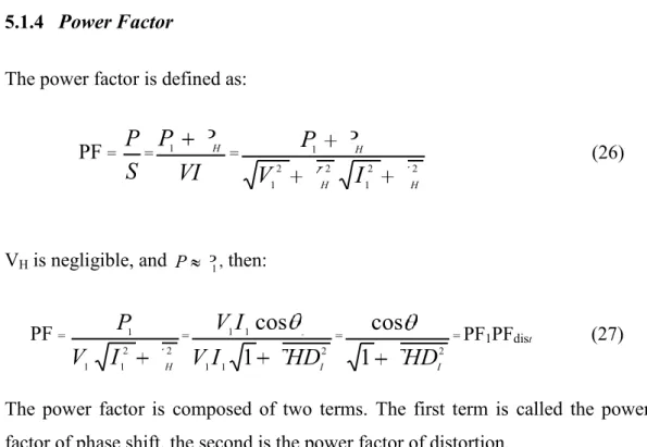
5.1.4 Power Factor
The power factor is defined as:
PF =
S
P
=VI
P
P
1 H = 2 2 1 2 2 1 1 H H HI
I
V
V
P
P
(26)VH is negligible, and P P1, then:
PF = 2 2 1 1 1 H
I
I
V
P
= 2 1 1 1 1 11
cos
ITHD
I
V
I
V
= 2 11
cos
ITHD
= PF1PFdist (27)The power factor is composed of two terms. The first term is called the power factor of phase shift, the second is the power factor of distortion.
5.2 Measurements of power
The measurements are performed on a 15 W CFL lamp A and lamp B LED 7W. The values stated by the manufacturers are shown in Table I:
Table IV. Technical specifications of lamps differenttypes of lamps
34
The experimental work was conducted with measurements at rated voltage of 220V and frequency of 50Hz. The mains voltage has a very limited distortion, and therefore is considered sinusoidal waveform of the voltage applied to the CFL and LED is shown in Fig 1.
Fig 5.1 Voltage applied to the lamps CFL and LED
You have performed various tests and were detected waveforms of current. In Fig 2 shows the waveform of the current absorbed by the lamp CFL.
35
Following instrumental measurement it was found that such waveform has the following characteristics:
rms value of the waveform = 102mA rms value of the first harmonic = 69mA
Total harmonic distortion of current THDI = 109%
Power factor PF = 2 1 1 1
1
THD
II
V
P
= 0,573The waveforms recorded clearly show that the current drawn by the lamp CFL is strongly distorted, the THDI worth 109%, with a significant deviation from the value relative to the sinusoidal behavior (THDI = 0). From measurements performed in the network it was verified that the supply voltage to the terminals of the lamp is almost sinusoidal and the THDV worth 2.2%. By performing similar tests in the case of LED lamp, the waveforms of the input current were detected. The Fig 3 shows the waveform of the current absorbed by the LED lamp:
36
Following instrumental measurement it was found that such waveform has the following characteristics:
rms value of the waveform I = 41,5 mA rms value of the first harmonic I = 33 mA1
Total harmonic distortion of current THDI = 76,2%
Power Factor PF= 2 1 1 1 1 THDI I V P = 0,694
With reference to the tests carried out, it can be said that the waveform of the current drawn by the LED lamp is much less distorted than that absorbed by the CFL, with a THDI decidedly lower and a higher power factor.
Measured quantities CFL LED V Rms nominal voltage applied (V) 220 220 THDV Harmonic distortion of the voltage (%) 2,2 2,06
V1
Fundamental harmonic of the voltage (V)
V)
219,94 219,95 VH Rms value of harmonic distortion of the voltage (V) 4,8 4,5
I Rms total current consumption (mA) 102 41,5 THDI Harmonic distortion of current (%) 109 76,2
I1 Fundamental harmonic of the current consumption (mA) 69 33
IH Value of rms harmonic distortion of the current (mA) 75,2 25,2
S Total apparent power (VA) 22,44 9,1 S1 Apparent power of the fundamental harmonic (VA) 15,17 7,3
SN Apparent power of the not fundamental harmonics (VA) 16,5 5,4
P Total active power (W) 12,9 6,33
Q1 Reactive power of the fundamental (var) 7,12 3,6
Q Total reactive power (var) 17,9 6,6 QH Reactive power of the not fundamental harmonics (var) 16,5 5,5
PF Power Factor 0,573 0,694
37
Were also carried out a series of measures to variable voltage, assuming that the network takes values of voltage lower or higher than the rated voltage. The data obtained are reported in the following figures.
In particular, the Figure 4 shows the input current (effective value of the current of line) from the CFL with variable voltage from 130V to 230V. The Fig 5 shows the variation of the active power in the same range of variation of the previous voltage. The Fig 6 shows the total power factor, and the Figure 7 the total apparent power and in Figure 7 the total apparent power to vary of the supply voltage in the same range of values previously reported. The figures equivalent to those already mentioned for the CFL lamp, for the LED lamp are shown respectively in Figs 8-11.
Line current (rms value) absorbed by the CFL lamp to vary the supply voltage
I (mA))
Line current (rms value) absorbed by the LED lamp to vary the supply voltage
38
Active power absorbed by the CFL lamp to vary the supply voltage
P (W)
Active power absorbed by the CFL lamp to vary the supply voltage
39
Apparent power absorbed by the CFL when the voltage changes
Q (VA)
Apparent power absorbed by the LED when the voltage changes
40
As can be seen from the curves shown above, the total current (in rms) absorbed by the CFL, increases to grow of the voltage with parabolic trend. The total current, rms, absorbed by the LED lamp grows rapidly with the voltage only in the range of values 140-170V and at the voltage of 170 V reaches the value of current of 42.6 mA, value slightly greater than the value of rated current; then in the range of voltage values from 170 to 230V decreases slowly with almost linear until it reaches its nominal value. Then in the significant range of values of voltage from 170-230V, the current drawn by the LED lamp (rms) has a
Power factor of the CFL lamp to vary the supply voltage
PF
Power factor of the LED lamp to vary the supply voltage
41
maximum variation (in the range of these values of voltage) of 5.7% of its nominal value, while the current drawn by the lamp CFL has a variation of 9% of its nominal value. What said is also reflected in the absorption of active power to vary of the supply voltage.
In fact, the active power of the CFL varies with a law linearly increasing to grow of the voltage . So the CFL it behaves as a load strongly voltage-dependent, and this should be considered his model in the power system. The active power of the LED lamps is less dependent on the voltage and varies with parabolic trend (similar to the variation of an incandescent lamp with reference only to the power). And in fact in the range of voltages from 170-230V, the active power of the CFL has a maximum variation of 26% of its nominal value, while the active power of a LED lamp has a maximum variation of 17%. The same applies for the total apparent power absorbed by the two lamps to vary of the supply voltage, whose curves have trends very similar to the respective curves shown for the active power. In fact, in the same range of voltage values from 170-230V, the apparent power of the CFL has a maximum variation of 33% of its nominal value, while the apparent power of the LED lamp has a maximum variation of 23%.
The power factors of the load, consists of both lamps, have a similar behavior, in fact it decreases with increasing of the voltage. Therefore for voltage values lower than the nominal value, the power factor assumes higher values of its nominal value. It should however is noted that for values of voltage lower than 180V, the power factor of the LED lamp grows very rapidly with decreasing of
42
CONCLUSIONS
This study has reviewed the main lighting parameters of the light sources, and their main properties, and highlighted features, strengths and weaknesses. We analyzed the technical and economic differences between the two main types of lamps, CFL and LED. The LED lamp shows remarkable properties not possessed by other light sources.
The comparison between the two technologies of lamps has been extended by means of experimental measurements. The best electrical characteristics on the main arising from the use of the LED lamp with respect to the use of CFL are evident from the measurements performed with the power supply analyzer. As said before, the main performances refer specifically to the harmonic distortion, and the maintenance of such good characteristics of the load in varying conditions of the supply voltage.
For a better understanding of the prerogatives of LED lamps, other important features must be considered: (1) the LED lamp does not contain toxic substances, and therefore no environmental pollution while the CFL contains small amounts of mercury; (2) the LED lamp has an average life much higher, which among other things leads to limited maintenance; 3) has ignition time zero; 4) allows easy control of the brightness (the emitted light is proportional to the bias current LED itself) and color (mixing multiple monochromatic LEDs), 5) absence of UV emission.
Unfortunately, today the technology of LED lamp is still not competitive in terms of cost with that of CFL. Over the past twenty years we have seen a progressive increase of the CFL that have actually supplanted the traditional incandescent lamps, now banned from the market. It is therefore expected in the years to come that the same thing could happen to the LED lamps, and this will be possible if the technology will be improved, so that the LED lamp can be produced at lower costs to economically compete with the CFL.
43
To obtain a significant reduction of the production costs, it is necessary to optimize every single part of the design of the lamp, the technology of production of the semiconductor parts, the optimization of the architecture of driving circuit, where possible reducing the number of components.
44
Bibliografia
[1] L IEEE-1459-2010 Standard, “IEEE Standard definitions for the Measurements of Electric Power Quantities Under Sinusoidal, Nonsinusoidal, Balanced or Unbalanced Conditions”, IEEE, 2010.
. 269-281
[2] Emanuel, A. E., “On the assessment of harmonic pollution,” IEEE
Transactions on Power Delivery vol. 10, no. 3, July 1995.
[3] IEEE Working Group on Non-sinusoidal Situations, “Practical definitions for powers in systems with non-sinusoidal waveforms and unbalanced loads,” IEEE Transactions on Power Delivery, vol. 11, no. 1, Jan. 1996.
[4] Cataliotti A., Cosentino V., and Nuccio S., “The measurement of reactive energy in polluted distribution power systems: an analysis of the performance of commercial static meters,” IEEE Transactions on Power Delivery, vol. 23, no. 3, July 2008.
[5] Filipski P. S., Baghzouz Y., and Cox M. D., “Discussion of Power Definitions Contained in the IEEE Dictionary,” IEEE Transactions on Power
Delivery, vol. 9, no. 3, July 1994,
[6] F. Bisegna, M. Barbalace, F. Gugliermetti: “Stato dell’arte dei LED (light emitting diode)”. Dipartimento di Fisica tecnica, Università di Roma ‘La Sapienza’. Giugno 2010
45
[7] S. K Ronnberg, M.H.J. Bollen, and M Wahlberg “Harmonic emission before and after changing to LED and CF, Part I: laboratory measurements for a domestic customer”. 2010
[8] J.Cunill-Sola, M. Salichs, “Study and Characterization of Waveforms from Low-watt (< 25 W) Compact Fluorescent Lamps with Electronic Ballasts”,
IEEE Tr. Power Delivery, Vol. 22, 2007
[9] Gianni Forcolini, “Illuminazione LED”. Copyright Ulrico Hoepli Editore. Milano, 2008.
[10] JF. Bisegna, M. Barbalace, F. Gugliermetti: “Stato dell’arte dei LED (light emitting diode)”. Dipartimento di Fisica tecnica, Università di Roma ‘La Sapienza’. Giugno 2010.
[11] CREE Datasheet, "XLamp XP-G LEDs". Copyright 2009-2010 Cree.
[12] Catalogo Philips, Osram, Sharp, Tess, Lednovation, Zetalux, Ledtronics, Ledrise. 2010.
[13] ] Gazzetta Ufficiale "Bando graduale dal mercato delle lampadine a incandescenza". Regolamento 244/2009/CE.
46
47
Un ringraziamento vero al Prof. Fortuna che, oltre ad avermi aiutato nel lavoro di tesi, ha creduto in me in un momento delicato della mia vita, trasmettendomi quella forza che mi è stata necessaria per concretizzare il sacrificio di un’intera vita di studio.
48