nanomaterials
Review
Iron-Based Nanomaterials/Graphene Composites for
Advanced Electrochemical Sensors
Kaveh Movlaee1,2, Mohmmad Reza Ganjali1, Parviz Norouzi1and Giovanni Neri2,* ID 1 Center of Excellence in Electrochemistry, School of Chemistry, College of Science, University of Tehran,
14155-6455 Tehran, Iran; [email protected] (K.M.); [email protected] (M.R.G.); [email protected]. (P.N.)
2 Department of Engineering, University of Messina, I-98166 Messina, Italy * Correspondence: [email protected]; Tel.: +39-090-397-7297
Received: 10 October 2017; Accepted: 16 November 2017; Published: 23 November 2017
Abstract:Iron oxide nanostructures (IONs) in combination with graphene or its derivatives—e.g., graphene oxide and reduced graphene oxide—hold great promise toward engineering of efficient nanocomposites for enhancing the performance of advanced devices in many applicative fields. Due to the peculiar electrical and electrocatalytic properties displayed by composite structures in nanoscale dimensions, increasing efforts have been directed in recent years toward tailoring the properties of IONs-graphene based nanocomposites for developing more efficient electrochemical sensors. In the present feature paper, we first reviewed the various routes for synthesizing IONs-graphene nanostructures, highlighting advantages, disadvantages and the key synthesis parameters for each method. Then, a comprehensive discussion is presented in the case of application of IONs-graphene based composites in electrochemical sensors for the determination of various kinds of (bio)chemical substances.
Keywords:iron oxide; hematite; magnetite; maghemite; synthesis; electrochemical sensors
1. Introduction
In nanoscale domain, materials often exhibit chemical and physical properties which cannot be observed neither in bulk nor in atom counterparts. Therefore, a great deal of effort has been devoted to prepare nanostructures which offer the desired properties. Thanks to their elegant properties and simplicity of synthesis in laboratory, iron oxide nanostructures (IONs) have achieved a unique position among other nanosized metal oxides [1,2]. Electrical, optical, magnetic and catalytic properties of iron based materials have been exploited for realizing many different purposes in a vast variety of research items. They have been extensively used in supercapacitors, data storage, lithium ion batteries, catalysis, drug delivery, therapeutic agents as well as water treatment [3,4]. Nevertheless, in many cases, it was necessary to combine iron nanostructures with other materials in order to obtain nanocomposites with enhanced performance. In this regard, graphene has shown a great potential to be a valuable option for synthesizing iron oxide/graphene nanocomposites. These hybrid nanostructures have been largely proposed and used for developing advanced devices in many applicative fields. In the chemical sensor field, IONs are exploited extensively as the sensing element part due to their unique electrical and electrocatalytic properties. Among them, electrochemical sensors for the detection of (bio)chemical substances are receiving increasing attention for medical, biological, environmental and industrial applications. Electrochemical sensors provide an attractive means to analyze a variety of analytes in physiological body fluids, food samples, environmental samples and industrial samples, due to the direct conversion of an electrochemical process to an electronic signal. For these characteristics, along with the simple use and low cost, the research for high-performance electrochemical sensors has experienced an explosive growth over the last two decades.
Nanomaterials 2017, 7, 406 2 of 33
This review will describe iron-based nanomaterials/graphene composites for advanced electrochemical sensors and begin with an introductory part describing the characteristics of the main iron oxide phases used in this regard. Among the different forms of iron oxides [1,2] the most abundant in the nature are hematite (α-Fe2O3), maghemite (γ-Fe2O3) and magnetite (Fe3O4). It is noteworthy that all these forms of iron oxide can also be produced from each other using reducing or oxidizing annealing procedure [2]. As will be seen in the next, magnetite has been largely used in the electrochemical sensor field, however, even if less used, maghemite and hematite show also some interesting applications in this area.
The next section is devoted to acquainting the reader with the most commonly used methods of synthesizing iron oxide nanostructures, along with introducing the advantages, disadvantages and effective parameters of each method. After that, we briefly present information about graphene and, finally, in the last section we will discuss and summarize application of different kinds of composites in which iron nanostructure and graphene have been exploited for the qualitative and quantitative determination of (bio)chemical substances.
2. Iron Oxides Nanostructures
Previous published papers related to application of IONs in biochemical detection, deal almost exclusively with hematite, maghemite and magnetite. Therefore, in this review we will mainly focus on them and recommend readers to use other good references for finding extra information about other phases of iron oxides [1,3,4].
2.1. Hematite (α-Fe2O3)
Hematite as the oldest known member of iron oxides family is an n-type semiconductor with a band gap of 2.3 eV under ambient conditions which is widespread in rocks and soils and it has shown promising capability in the fields of gas sensors [5,6], pigments [7,8], energy storages [9–12] and biochemical detections [13–15]. This form of iron oxide is highly stable and it is usually the final product of transformation of other iron oxides. If finely divided, hematite has red color and where it is coarsely crystalline shows grey or black color [16]. In hematite structures, empty d-orbitals of Fe3+make conduction band whereas the valence band is made by occupied 3d crystal field orbitals of Fe3+with some admixture from the O 2p non-bonding orbitals [2,17,18]. As shown in Figure1a, Fe(III) ions fill two-thirds of octahedral positions, which are surrounded with O lattice in almost perfect hexagonal close-packed.
Nanomaterials 2017, 7, 406 2 of 31
and low cost, the research for high-performance electrochemical sensors has experienced an explosive growth over the last two decades.
This review will describe iron-based nanomaterials/graphene composites for advanced electrochemical sensors and begin with an introductory part describing the characteristics of the main iron oxide phases used in this regard. Among the different forms of iron oxides [1,2] the most abundant in the nature are hematite (α-Fe2O3), maghemite (γ-Fe2O3) and magnetite (Fe3O4). It is
noteworthy that all these forms of iron oxide can also be produced from each other using reducing or oxidizing annealing procedure [2]. As will be seen in the next, magnetite has been largely used in the electrochemical sensor field, however, even if less used, maghemite and hematite show also some interesting applications in this area.
The next section is devoted to acquainting the reader with the most commonly used methods of synthesizing iron oxide nanostructures, along with introducing the advantages, disadvantages and effective parameters of each method. After that, we briefly present information about graphene and, finally, in the last section we will discuss and summarize application of different kinds of composites in which iron nanostructure and graphene have been exploited for the qualitative and quantitative determination of (bio)chemical substances.
2. Iron Oxides Nanostructures
Previous published papers related to application of IONs in biochemical detection, deal almost exclusively with hematite, maghemite and magnetite. Therefore, in this review we will mainly focus on them and recommend readers to use other good references for finding extra information about other phases of iron oxides [1,3,4].
2.1. Hematite (α-Fe2O3)
Hematite as the oldest known member of iron oxides family is an n-type semiconductor with a band gap of 2.3 eV under ambient conditions which is widespread in rocks and soils and it has shown promising capability in the fields of gas sensors [5,6], pigments [7,8], energy storages [9–12] and biochemical detections [13–15]. This form of iron oxide is highly stable and it is usually the final product of transformation of other iron oxides. If finely divided, hematite has red color and where it is coarsely crystalline shows grey or black color [16]. In hematite structures, empty d-orbitals of Fe3+
make conduction band whereas the valence band is made by occupied 3d crystal field orbitals of Fe3+
with some admixture from the O 2p non-bonding orbitals [2,17,18]. As shown in Figure 1a, Fe(III) ions fill two-thirds of octahedral positions, which are surrounded with O lattice in almost perfect hexagonal close-packed.
Figure 1. Crystal structures of (a) hematite and (b) magnetite. Reproduced with permission from [3]. Elsevier, 2009.
Figure 1.Crystal structures of (a) hematite and (b) magnetite. Reproduced with permission from [3]. Elsevier, 2009.
Nanomaterials 2017, 7, 406 3 of 33
2.2. Maghemite (γ-Fe2O3)
Maghemite is the second most stable form of iron oxides, which is considered as fully oxidized magnetite, see Section2.3, can be found in natural sources, e.g., soils. Maghemite is weathering product of magnetite to which it is structurally related. Both magnetite and maghemite have a spinel crystal structure, however, while Fe3O4contains both di and trivalent iron cations, in maghemite most or all the iron cations are in the form of Fe3+and cation vacancies compensate oxidation of Fe2+[19,20]. In inverse spinel structure of maghemite, Fe(III) ions have been scattered between tetrahedral and octahedral sites. Maghemite shows an n-type semiconductor behavior with a band gap of 2.0 eV [2]. While hematite exhibits antiferromagnetic properties, maghemite is considered as ferromagnetic material which has led to its widespread application in different fields. At about 400◦C, γ-Fe2O3is converted irreversibly to α-Fe2O3and magnetization will remarkably loss during this conversion [3]. 2.3. Magnetite (Fe3O4)
Magnetite, FeIIFeIII2O4, is also called iron (II, III) oxide or ferrous ferrite. The molecular formula of magnetite, Fe3O4, can be shown as (FeO·Fe2O3). Among all the natural minerals in earth, magnetite possesses the strongest magnetism [21]. Magnetite differs from most other iron oxides since it contains both Fe2+and Fe3+ions. Fe3O4has a cubic inverse spinel structure that consists of a cubic close packed array of oxide ions, where tetrahedral site is occupied by Fe3+ions surrounded by four O atoms, while octahedral site is occupied with both Fe2+and Fe3+ions surrounded by six oxygen atoms (Figure1b). Therefore, Fe3+exists in both tetrahedral and octahedral sites [20]. In magnetite, Fe2+can be fully or partly replaced by other divalent ions such as Co, Mn and Zn. Therefore, magnetite can be both n-type and p-type semiconductor. Owning to its small band gap, 0.1 eV, magnetite has the lowest resistivity among iron oxides [2]. Additionally, fast electron hopping between the Fe2+and Fe3+ions at the octahedral sites brings about high conductivity of Fe3O4insofar as magnetite can be considered as half metal [20].
3. Preparation Methods of IONs
Since size and shape of nanostructures, size distribution and surface chemistry have great impact on features and behaviors of IONs, preparation methods play a key role in practical aspects. Also, the preparation method determines the degree of structural defects and impurities present in the particles as well as the distribution of such defects thereby manipulation of behaviors of IONs can be achieved. Although IONs can be synthesized in different ways [22], here we introduce just the 4 most commonly used methods which have been extensively exploited for preparation of IONs, i.e., hydrothermal, co-precipitation, microemulsion and sol-gel methods.
3.1. Hydrothermal Method
The hydrothermal method is one of the most useful techniques, not only for iron oxide preparation but also for synthesizing other inorganic nanocrystals, especially for metals and metal oxides [20]. Hydrothermal reactions take place in aqueous media in autoclave or reactor where temperature usually needs to be more than 200◦C and the pressure needs to be higher than 13,800 kPa, about 2000 psi, for iron oxide preparation [21].
At such high temperature and pressure, metal salts can be undergone hydrolyze and dehydration by water. Consequently, supersaturation is generated due to extremely low solubility of the obtained metal oxides in aqueous media at these elevated pressure and temperature [23]. The elevated temperatures enhance dehydration rates and cause the high diffusivity of reactants in such situations. High supersaturation obtains in this procedure due to the extremely low solubility of metal oxides and hydroxides and finally very fine crystals are prepared [3]. Duo to synergistic effect of high temperatures and pressures the quality of the nanocrystals and hence their magnetic features improve significantly [24]. Some parameters like temperature, pressure, reaction time, type and concentration
Nanomaterials 2017, 7, 406 4 of 33
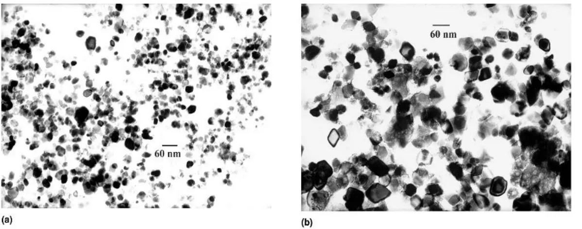
of precursors can be changed in order to obtain desired shape and/or size of products. Hydrothermal process is environmental friendly since there is no need for using organic solvents or post-treatments. Therefore, hydrothermal technique has been widely used to synthesis metal oxides as powders, nanoparticles and single crystals. Effect of temperature, precursor concentration and reaction time on particle morphology and size in hydrothermal method were investigated by Hao et al. [25]. The particle size and size distribution increased with precursor concentration (see Figure2). However, the reaction time had stronger effect on the average particle size than feed concentration. Effect of temperature and reaction time can be understood by considering that the formation of the particles occurs in two steps: first nucleation and then crystal growth. At higher temperatures, the nucleation process is faster than the crystal growth, so particles with lower size are obtain; on the other hand, larger particles are produced as a result of longer reaction time where crystal growth becomes determining factor [21,26].
Nanomaterials 2017, 7, 406 4 of 31 Hydrothermal process is environmental friendly since there is no need for using organic solvents or post-treatments. Therefore, hydrothermal technique has been widely used to synthesis metal oxides as powders, nanoparticles and single crystals. Effect of temperature, precursor concentration and reaction time on particle morphology and size in hydrothermal method were investigated by Hao et al. [25]. The particle size and size distribution increased with precursor concentration (see Figure 2). However, the reaction time had stronger effect on the average particle size than feed concentration. Effect of temperature and reaction time can be understood by considering that the formation of the particles occurs in two steps: first nucleation and then crystal growth. At higher temperatures, the nucleation process is faster than the crystal growth, so particles with lower size are obtain; on the other hand, larger particles are produced as a result of longer reaction time where crystal growth becomes determining factor [21,26].
Figure 2. TEM (transmission electron microscopy) pictures of iron oxide nanoparticles obtained at a
reactor temperature of 573 K and residence time of 12 s: (a) iron feed 0.03 M; (b) iron feed 0.50 M. Reproduced with permission from [25]. Cambridge University Press, 2011.
3.2. Coprecipitation
Coprecipitation is one of the cheapest, simplest and the most environmental-friendly ways for preparation of IONs which involves the simultaneous precipitation of Fe2+ and Fe3+ ions in basic
aqueous media [24]. A complete precipitation of Fe3O4 is expected to take place in a media with pH
between 9 and 14, while molar ratio of Fe3+:Fe2+ is 2:1 under a non-oxidizing oxygen-free
environment. Fe3O4 is not very stable, then it can be oxidized into maghemite in the presence of
oxygen in solution phase, therefore, in these cases, using of an oxygen free media is necessary to obtain magnetite.
This method is frequently used in the aqueous phase synthesis of Fe3O4 nanoparticles.
Generally, this method exploits a basic solution, such as sodium hydroxide or ammonia solution to precipitate Fe2+ and Fe3+. The surface of as-produced IONs is rich of OH groups and these IONs can
be easily dispersed in aqueous media [20]. Refait and Olowe proposed a mechanism in which Fe(OH)2 can serve as an intermediate for Fe3O4 formation. The mechanism consists of the
precipitation of Fe2+ by alkaline, the oxidation of Fe(OH)2 by oxygen to FeOOH and the combination
of Fe(OH)2 and FeOOH to form Fe3O4. Therefore, they proposed that even if only Fe2+ was used as
the precursor, Fe3O4 nanoparticles can be formed using co-precipitation method under air and using
Fe3+ as precursors is not necessary [20]. Hui et al. prepared large-scale hydrophilic Fe3O4
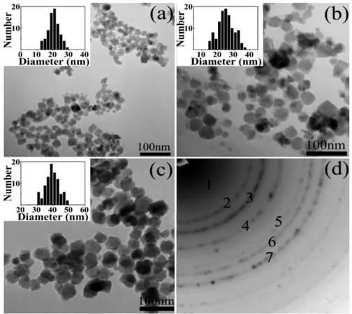
nanoparticles and showed possibility of controlling over particle size in the range of 20 to 40 nm by tuning the experimental parameters such as precursor concentration, temperature and ionic strength [27]. Here FeSO4·4H2O was used as precursor to produce magnetite. As shown in Figure 3,
decreasing the ferrous precursor concentration from 0.1 to 0.02 M results in an increase of average size from 20 to 40 nm; for instance, a mean diameter of about 20 nm is obtained by using 0.10 M Fe2+
Figure 2.TEM (transmission electron microscopy) pictures of iron oxide nanoparticles obtained at a reactor temperature of 573 K and residence time of 12 s: (a) iron feed 0.03 M; (b) iron feed 0.50 M. Reproduced with permission from [25]. Cambridge University Press, 2011.
3.2. Coprecipitation
Coprecipitation is one of the cheapest, simplest and the most environmental-friendly ways for preparation of IONs which involves the simultaneous precipitation of Fe2+and Fe3+ions in basic aqueous media [24]. A complete precipitation of Fe3O4is expected to take place in a media with pH between 9 and 14, while molar ratio of Fe3+:Fe2+is 2:1 under a non-oxidizing oxygen-free environment. Fe3O4is not very stable, then it can be oxidized into maghemite in the presence of oxygen in solution phase, therefore, in these cases, using of an oxygen free media is necessary to obtain magnetite.
This method is frequently used in the aqueous phase synthesis of Fe3O4nanoparticles. Generally, this method exploits a basic solution, such as sodium hydroxide or ammonia solution to precipitate Fe2+and Fe3+. The surface of as-produced IONs is rich of OH groups and these IONs can be easily dispersed in aqueous media [20]. Refait and Olowe proposed a mechanism in which Fe(OH)2can serve as an intermediate for Fe3O4formation. The mechanism consists of the precipitation of Fe2+by alkaline, the oxidation of Fe(OH)2by oxygen to FeOOH and the combination of Fe(OH)2and FeOOH to form Fe3O4. Therefore, they proposed that even if only Fe2+was used as the precursor, Fe3O4 nanoparticles can be formed using co-precipitation method under air and using Fe3+as precursors is not necessary [20]. Hui et al. prepared large-scale hydrophilic Fe3O4nanoparticles and showed possibility of controlling over particle size in the range of 20 to 40 nm by tuning the experimental parameters such as precursor concentration, temperature and ionic strength [27]. Here FeSO4·4H2O was used as precursor to produce magnetite. As shown in Figure3, decreasing the ferrous precursor concentration from 0.1 to 0.02 M results in an increase of average size from 20 to 40 nm; for instance, a mean diameter of about 20 nm is obtained by using 0.10 M Fe2+solution. In Figure3d result of
Nanomaterials 2017, 7, 406 5 of 33
selected area electron diffraction, SAED, for 20-nm Fe3O4NPs has been shown which is an illustration for magnetic structure of this sample.
Nanomaterials 2017, 7, 406 5 of 31
solution. In Figure 3d result of selected area electron diffraction, SAED, for 20-nm Fe3O4 NPs has
been shown which is an illustration for magnetic structure of this sample.
Figure 3. (a–c) TEM images and size distributions of Fe3O4 nanoparticles (NPs) with the different
mean diameters of 20 nm (a,) σ = 16%, 25 nm (b) σ = 19% and 40 nm (c) σ = 10%. The size distributions show that the synthesized Fe3O4 NPs had a narrow size distribution. (d) Electron diffraction (ED)
patterns of the 20-nm Fe3O4 NPs. Reproduced with permission from [27]. American Chemical
Society, 2008.
If the concentration of the Fe2+ was decreased to 0.05 and 0.02 M, 25 and 40 nm Fe3O4
nanoparticles would be produced, respectively. This observation can be explained in this way that concentration of Fe2+ strongly affects both nucleation and growth rate of Fe3O4 particles. The higher
initial precursor concentration, the smaller particles size due to the formation of a large number of seeds which provide high particle concentration and yield smaller particles.
3.3. Sol-Gel
This method generally refers to the hydrolysis and condensation of alkoxide precursors and producing a sol which is a dispersion of nanoparticles. Usual precursors for IONs preparation are iron alkoxides and iron salts like chlorides, nitrates and acetates which are undergone various forms of hydrolysis and condensation reactions. Additional condensation and inorganic polymerization causes to form a 3D metal oxide network named as wet gel. Since the reactions are done at ambient, additional heat treatments are required to obtain the final crystalline state [28]. Water is generally used as solvent but precursors can be hydrolyzed by an acid or base. Basic catalysis causes the formation of a colloidal gel whereas acid catalysis results in a polymeric form of the gel [3]. Properties of the final products strongly depend on the rates of hydrolysis and condensation. Smaller particle size is obtained at slower and more controlled hydrolysis rates. Particle size also depends on the solution composition, temperature and pH of solution [2]. It is of great importance to control the rate of hydrolysis and condensation of gel procurers as well as other redox reactions which take place in gelling stage and heat treatments after that since these variables have great impact on structural features and porosity of the final products. Cui et al. [29] synthesized nearly
Figure 3.(a–c) TEM images and size distributions of Fe3O4nanoparticles (NPs) with the different mean diameters of 20 nm, (a) σ = 16%, 25 nm (b) σ = 19% and 40 nm (c) σ = 10%. The size distributions show that the synthesized Fe3O4NPs had a narrow size distribution. (d) Electron diffraction (ED) patterns of the 20-nm Fe3O4NPs. Reproduced with permission from [27]. American Chemical Society, 2008.
If the concentration of the Fe2+was decreased to 0.05 and 0.02 M, 25 and 40 nm Fe3O4nanoparticles would be produced, respectively. This observation can be explained in this way that concentration of Fe2+strongly affects both nucleation and growth rate of Fe3O4particles. The higher initial precursor concentration, the smaller particles size due to the formation of a large number of seeds which provide high particle concentration and yield smaller particles.
3.3. Sol-Gel
This method generally refers to the hydrolysis and condensation of alkoxide precursors and producing a sol which is a dispersion of nanoparticles. Usual precursors for IONs preparation are iron alkoxides and iron salts like chlorides, nitrates and acetates which are undergone various forms of hydrolysis and condensation reactions. Additional condensation and inorganic polymerization causes to form a 3D metal oxide network named as wet gel. Since the reactions are done at ambient, additional heat treatments are required to obtain the final crystalline state [28]. Water is generally used as solvent but precursors can be hydrolyzed by an acid or base. Basic catalysis causes the formation of a colloidal gel whereas acid catalysis results in a polymeric form of the gel [3]. Properties of the final products strongly depend on the rates of hydrolysis and condensation. Smaller particle size is obtained at slower and more controlled hydrolysis rates. Particle size also depends on the solution composition, temperature and pH of solution [2]. It is of great importance to control the rate of hydrolysis and condensation of gel procurers as well as other redox reactions which take place in gelling stage and heat treatments after that since these variables have great impact on structural
Nanomaterials 2017, 7, 406 6 of 33
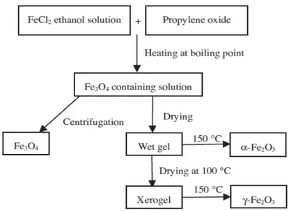
features and porosity of the final products. Cui et al. [29] synthesized nearly monodispersed Fe3O4, α-Fe2O3and γ-Fe2O3nanoparticles using a low temperature sol-gel method with same procedure and same starting materials (see Figure4). The preparation procedure includes the reaction of FeCl2in boiling ethanol solution with propylene oxide to form a sol solution followed by a drying procedure. Structures of produced IONs easily changed by changing of drying conditions for the sol solution [29].
Nanomaterials 2017, 7, 406 6 of 31
monodispersed Fe3O4, α-Fe2O3 and γ-Fe2O3 nanoparticles using a low temperature sol-gel method
with same procedure and same starting materials (see Figure 4). The preparation procedure includes the reaction of FeCl2 in boiling ethanol solution with propylene oxide to form a sol solution followed
by a drying procedure. Structures of produced IONs easily changed by changing of drying conditions for the sol solution [29].
Figure 4. Generalized scheme for the preparation of α-Fe2O3, γ-Fe2O3 and Fe3O4 nanoparticles.
Reproduced with permission from [29]. Elsevier, 2013. 3.4. Microemulsion
A microemulsion is defined as a thermodynamically stable isotropic dispersion of two relatively immiscible liquids that have been stabilized by cationic, anionic and/or non-ionic surfactant like Triton-X. Microemulsions are often clear and stable liquid mixtures of oil, water and surfactant, usually together with a co-surfactant that have been widely used to obtain IONs [2,30–34]. Base on relative concentrations, surfactant molecules self-assemble into different structures in mixture including micelles, bilayers and vesicles. However, micelles are commonly used structures in nanoparticle synthesis, either as normal (oil in water or o/w) or reverse (water in oil or w/o) micelle [35]. In both cases, monodispersed droplets in the size range of 2–100 nm can be produced. This dispersed phase provides a confined environment for synthesizing nanoscale particles. The surfactant-covered water pools produce favorable nano or microenvironments for formation of nanoparticles and, at the same time, for limiting nanoparticles growth. The size of the microemulsion droplets is related to the water to surfactant ratio, although the final size of the nanoparticles may also be changed duo to other parameters like concentration of reactants and flexibility of the surfactant film [3].
Different ways can be used to produce nanoparticles using microemulsion technique (see Figure 5). For instance, precursors A and B are dissolved in the aqueous phases of two similar w/o microemulsions to form an AB precipitate during mixing. The precipitate is confined to the interior of the droplets thereby size and shape of the particles are determined by droplet size (Figure 5a). In another way, nanoparticles are prepared by adding a precipitating or reducing substance to a microemulsion. This microemulsion consists of the primary reactants which have already been dissolved in an aqueous solution (Figure 5b). These precipitating or reducing substances can be either a gas, e.g., hydrogen, or a liquid, e.g., hydrazine. Figure 5c shows another way to produce carbonate, oxide or hydroxide precipitates. Here microemulsion which contains desired cations is subjected to appropriate bubbling gases such as NH3, CO2 or O2 in order to form IONs [3].
Figure 4. Generalized scheme for the preparation of α-Fe2O3, γ-Fe2O3 and Fe3O4 nanoparticles. Reproduced with permission from [29]. Elsevier, 2013.
3.4. Microemulsion
A microemulsion is defined as a thermodynamically stable isotropic dispersion of two relatively immiscible liquids that have been stabilized by cationic, anionic and/or non-ionic surfactant like Triton-X. Microemulsions are often clear and stable liquid mixtures of oil, water and surfactant, usually together with a co-surfactant that have been widely used to obtain IONs [2,30–34]. Base on relative concentrations, surfactant molecules self-assemble into different structures in mixture including micelles, bilayers and vesicles. However, micelles are commonly used structures in nanoparticle synthesis, either as normal (oil in water or O/W) or reverse (water in oil or W/O) micelle [35]. In both cases, monodispersed droplets in the size range of 2–100 nm can be produced. This dispersed phase provides a confined environment for synthesizing nanoscale particles. The surfactant-covered water pools produce favorable nano or microenvironments for formation of nanoparticles and, at the same time, for limiting nanoparticles growth. The size of the microemulsion droplets is related to the water to surfactant ratio, although the final size of the nanoparticles may also be changed duo to other parameters like concentration of reactants and flexibility of the surfactant film [3].
Different ways can be used to produce nanoparticles using microemulsion technique (see Figure5). For instance, precursors A and B are dissolved in the aqueous phases of two similar W/O microemulsions to form an AB precipitate during mixing. The precipitate is confined to the interior of the droplets thereby size and shape of the particles are determined by droplet size (Figure5a). In another way, nanoparticles are prepared by adding a precipitating or reducing substance to a microemulsion. This microemulsion consists of the primary reactants which have already been dissolved in an aqueous solution (Figure5b). These precipitating or reducing substances can be either a gas, e.g., hydrogen, or a liquid, e.g., hydrazine. Figure5c shows another way to produce carbonate, oxide or hydroxide precipitates. Here microemulsion which contains desired cations is subjected to appropriate bubbling gases such as NH3, CO2or O2in order to form IONs [3].
Nanomaterials 2017, 7, 406 7 of 33
Nanomaterials 2017, 7, 406 7 of 31
Figure 5. Schematic representation of nanoparticle synthesis in microemulsions (a) by mixing two
microemulsions; (b) by adding a reducing agent; and (c) by bubbling gas through the microemulsion. Reproduced with permission from [3]. Elsevier, 2009.
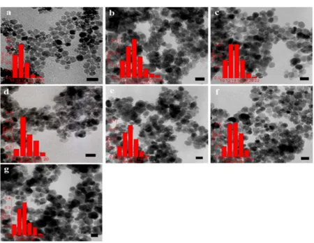
Lu and coworkers [34] extensively investigated the effect of surfactant on prepared IONs. As shown in Figure 6, different kinds of surfactants can alter the size and/or size distribution of final products. In this study, sodium dodecylsulfate, SDS, polyoxyethylene(4) lauryl ether, Brij30, dodecyltrimethylammonium bromide, DTAB, dodecyltriethylammoniumbromide, DEAB, dodecyltributylammonium bromide, DBAB, and cetyltrimethylammonium bromide, CTAB, were used.
Figure 6. TEM micrographs and size histograms for Fe3O4 nanoparticles prepared by microemulsion
method at 70 °C in (a) SDS; (b) Brij30; (c) DTAB; (d) DEAB; (e) DBAB; (f) CTAB; (g) 12-2-12. The scale bar is 20 nm. Reproduced with permission form [34]. Elsevier, 2013.
Figure 5. Schematic representation of nanoparticle synthesis in microemulsions (a) by mixing two microemulsions; (b) by adding a reducing agent; and (c) by bubbling gas through the microemulsion. Reproduced with permission from [3]. Elsevier, 2009.
Lu and coworkers [34] extensively investigated the effect of surfactant on prepared IONs. As shown in Figure 6, different kinds of surfactants can alter the size and/or size distribution of final products. In this study, sodium dodecylsulfate, SDS, polyoxyethylene(4) lauryl ether, Brij30, dodecyltrimethylammonium bromide, DTAB, dodecyltriethylammoniumbromide, DEAB, dodecyltributylammonium bromide, DBAB, and cetyltrimethylammonium bromide, CTAB, were used.
Nanomaterials 2017, 7, 406 7 of 31
Figure 5. Schematic representation of nanoparticle synthesis in microemulsions (a) by mixing two
microemulsions; (b) by adding a reducing agent; and (c) by bubbling gas through the microemulsion. Reproduced with permission from [3]. Elsevier, 2009.
Lu and coworkers [34] extensively investigated the effect of surfactant on prepared IONs. As shown in Figure 6, different kinds of surfactants can alter the size and/or size distribution of final products. In this study, sodium dodecylsulfate, SDS, polyoxyethylene(4) lauryl ether, Brij30, dodecyltrimethylammonium bromide, DTAB, dodecyltriethylammoniumbromide, DEAB, dodecyltributylammonium bromide, DBAB, and cetyltrimethylammonium bromide, CTAB, were used.
Figure 6. TEM micrographs and size histograms for Fe3O4 nanoparticles prepared by microemulsion
method at 70 °C in (a) SDS; (b) Brij30; (c) DTAB; (d) DEAB; (e) DBAB; (f) CTAB; (g) 12-2-12. The scale bar is 20 nm. Reproduced with permission form [34]. Elsevier, 2013.
Figure 6.TEM micrographs and size histograms for Fe3O4nanoparticles prepared by microemulsion method at 70◦C in (a) SDS; (b) Brij30; (c) DTAB; (d) DEAB; (e) DBAB; (f) CTAB; (g) 12-2-12. The scale bar is 20 nm. Reproduced with permission form [34]. Elsevier, 2013.
Nanomaterials 2017, 7, 406 8 of 33
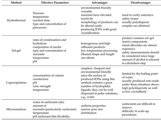
In Table1, effective parameters that influence on the final product as well as advantage and disadvantages of each method have been summarized.
Table 1.Different methods for IONs preparation, advantages, disadvantages and effective parameters.
Method Effective Parameters Advantages Disadvantages
Hydrothermal
Pressure temperature reaction time
type and concentration of precursors
environmental friendly versatile
reactants have elevated reactivity
morphology of products can be altered easily
producing IONs with good crystallization
need to costly autoclave safety issues
usually polydisperse samples are obtained
Sol-gel
rates of condensation and hydrolysis
composition of media type and concentration of reactants
temperature pH
homogenous and high adhesion products low temperature processing Desired shape and length can obtain
product contains sol–gel matrix components metal alkoxides are almost expensive
safety measurements should be considered since large amount of alcohol is released in calcination step Coprecipitation concentration of cations counterions pH ionic strength temperature
simplest, cheapest and environmental friendly since the surface of produced IONs using this method contains a great number of hydrophilic ligands, they can be well dispersed in polar solutions, e.g., water
limited by the boiling point of water
usually produced iron oxide under these situations shows high polydispersity as well as low crystallinity
Microemulsion
water to surfactant ratio amount of
reactants (particularly surfactant) temperature
pH surfactant film flexibility
uniform properties narrow pore size distribution
surfactants are difficult to remove
difficulty in scale-up procedures
4. Graphene
Graphene is a new member of an increasingly populated family of carbon allotropes (Figure7), which has famous members like graphite, diamond, carbon nanotube, fullerene, graphene, etc. [36].
Nanomaterials 2017, 7, 406 8 of 31
In Table 1, effective parameters that influence on the final product as well as advantage and disadvantages of each method have been summarized.
Table 1. Different methods for IONs preparation, advantages, disadvantages and effective parameters.
Method Effective Parameters Advantages Disadvantages
Hydrothermal
Pressure temperature reaction time
type and concentration of precursors
environmental friendly versatile
reactants have elevated reactivity morphology of products can be altered easily
producing IONs with good crystallization
need to costly autoclave safety issues
usually polydisperse samples are obtained
Sol-gel
rates of condensation and hydrolysis
composition of media type and concentration of reactants
temperature pH
homogenous and high adhesion products
low temperature processing Desired shape and length can obtain
product contains sol–gel matrix components
metal alkoxides are almost expensive
safety measurements should be considered since large amount of alcohol is released in calcination step Coprecipitation concentration of cations counterions pH ionic strength temperature
simplest, cheapest and environmental friendly
since the surface of produced IONs using this method contains a great number of hydrophilic ligands, they can be well dispersed in polar solutions, e.g., water
limited by the boiling point of water
usually produced iron oxide under these situations shows high polydispersity as well as low crystallinity
Microemulsion
water to surfactant ratio amount of
reactants (particularly surfactant)
temperature pH
surfactant film flexibility
uniform properties
narrow pore size distribution
surfactants are difficult to remove difficulty in scale-up procedures
4. Graphene
Graphene is a new member of an increasingly populated family of carbon allotropes (Figure 7), which has famous members like graphite, diamond, carbon nanotube, fullerene, graphene, etc. [36].
Figure 7. Allotropes of carbon and their crystal structures. Reproduced with permission from [36].
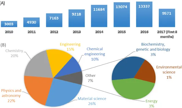
Graphene has been the center of attention of much scientific research since the early papers of Geim and Novoselov [37], for which they later shared the Nobel Prize in Physics in 2010. Figure 8 clearly shows this increased interest for exploiting of graphene and its derivatives such as graphite oxide, graphene oxide and reduced graphene oxide in scientific papers. Graphene, which refers to a two-dimensional layer of sp2 hybridized carbon atoms, exhibits exceptional optical, magnetic,
mechanical, electronic and thermal properties as wellas large specific surface area [38–40]. Due to these extraordinary properties, graphene and its derivatives have been extensively utilized in
Figure 7.Allotropes of carbon and their crystal structures. Reproduced with permission from [36]. Graphene has been the center of attention of much scientific research since the early papers of Geim and Novoselov [37], for which they later shared the Nobel Prize in Physics in 2010. Figure8
clearly shows this increased interest for exploiting of graphene and its derivatives such as graphite oxide, graphene oxide and reduced graphene oxide in scientific papers. Graphene, which refers to a two-dimensional layer of sp2hybridized carbon atoms, exhibits exceptional optical, magnetic,
Nanomaterials 2017, 7, 406 9 of 33
mechanical, electronic and thermal properties as well as large specific surface area [38–40]. Due to these extraordinary properties, graphene and its derivatives have been extensively utilized in different areas such as transparent electrode, energy storage, drug delivery, biosensing and catalysis to date [41–47].
Nanomaterials 2017, 7, 406 9 of 31
different areas such as transparent electrode, energy storage, drug delivery, biosensing and catalysis to date [41–47].
Figure 8. A comparative demonstration of published papers (since 2010 to date) according to Scopus data base searching “graphene” in title. (A) published papers since 2010; (B) categorized published papers in the first 8 scientific areas according to number of papers.
Graphite oxide possesses similar layered structure to graphite. However, the plane of carbon atoms in graphite oxide is heavily decorated by oxygen-containing groups such as hydroxyl, carboxyl, carbonyl and epoxy groups, which increase the interlayer distance and make these layers more hydrophilic. Therefore, these heavily oxidized layers are easily exfoliated in water under ultrasonication (Figure 9) [48].
Figure 9. (a) Chemical route to synthesize aqueous graphene dispersions; (b) The expected chemical structure of a single sheet of graphene oxide (GO); (c) AFM (atomic force microscopy) image of the GO on a silicon substrate showing an average thickness of around 1 nm. Reproduced with permission from [45]. Royal Society of Chemistry, 2012.
Graphene oxide (GO) and reduced graphene oxide (rGO) are other related materials to graphene. GO is layered and oxygenated graphene sheets containing oxygen functional groups and obtains easily as a suspension by exfoliation of graphite oxide. GO can be partially reduced to graphene-like sheets, rGO, by removing the oxygen-containing groups using various reduction methods although some residual oxygen and structural defects will remain even after reduction [48,49].
Figure 8.A comparative demonstration of published papers (since 2010 to date) according to Scopus data base searching “graphene” in title. (A) published papers since 2010; (B) categorized published papers in the first 8 scientific areas according to number of papers.
Graphite oxide possesses similar layered structure to graphite. However, the plane of carbon atoms in graphite oxide is heavily decorated by oxygen-containing groups such as hydroxyl, carboxyl, carbonyl and epoxy groups, which increase the interlayer distance and make these layers more hydrophilic. Therefore, these heavily oxidized layers are easily exfoliated in water under ultrasonication (Figure9) [48].
Nanomaterials 2017, 7, 406 9 of 31
different areas such as transparent electrode, energy storage, drug delivery, biosensing and catalysis to date [41–47].
Figure 8. A comparative demonstration of published papers (since 2010 to date) according to Scopus data base searching “graphene” in title. (A) published papers since 2010; (B) categorized published papers in the first 8 scientific areas according to number of papers.
Graphite oxide possesses similar layered structure to graphite. However, the plane of carbon atoms in graphite oxide is heavily decorated by oxygen-containing groups such as hydroxyl, carboxyl, carbonyl and epoxy groups, which increase the interlayer distance and make these layers more hydrophilic. Therefore, these heavily oxidized layers are easily exfoliated in water under ultrasonication (Figure 9) [48].
Figure 9. (a) Chemical route to synthesize aqueous graphene dispersions; (b) The expected chemical structure of a single sheet of graphene oxide (GO); (c) AFM (atomic force microscopy) image of the GO on a silicon substrate showing an average thickness of around 1 nm. Reproduced with permission from [45]. Royal Society of Chemistry, 2012.
Graphene oxide (GO) and reduced graphene oxide (rGO) are other related materials to graphene. GO is layered and oxygenated graphene sheets containing oxygen functional groups and obtains easily as a suspension by exfoliation of graphite oxide. GO can be partially reduced to graphene-like sheets, rGO, by removing the oxygen-containing groups using various reduction methods although some residual oxygen and structural defects will remain even after reduction [48,49].
Figure 9.(a) Chemical route to synthesize aqueous graphene dispersions; (b) The expected chemical structure of a single sheet of graphene oxide (GO); (c) AFM (atomic force microscopy) image of the GO on a silicon substrate showing an average thickness of around 1 nm. Reproduced with permission from [45]. Royal Society of Chemistry, 2012.
Graphene oxide (GO) and reduced graphene oxide (rGO) are other related materials to graphene. GO is layered and oxygenated graphene sheets containing oxygen functional groups and obtains easily as a suspension by exfoliation of graphite oxide. GO can be partially reduced to graphene-like sheets,
Nanomaterials 2017, 7, 406 10 of 33
rGO, by removing the oxygen-containing groups using various reduction methods although some residual oxygen and structural defects will remain even after reduction [48,49].
Synthesis methods of graphene or its related materials can be divided into two general categories namely top-down and bottom-up. Top-down approaches commence with exfoliation of graphite or graphite derivatives such as graphite oxide and graphite fluoride to create the final product e.g., GO or rGO. This approach can be cost effective and scalable depending on the initial materials and yield. In this approach, graphene or rGO are produced by either peeling, cleaving, separation or exfoliation of graphite or its derivatives (Figure10) [50].
Nanomaterials 2017, 7, 406 10 of 31
Synthesis methods of graphene or its related materials can be divided into two general categories namely top-down and bottom-up. Top-down approaches commence with exfoliation of graphite or graphite derivatives such as graphite oxide and graphite fluoride to create the final product e.g., GO or rGO. This approach can be cost effective and scalable depending on the initial materials and yield. In this approach, graphene or rGO are produced by either peeling, cleaving, separation or exfoliation of graphite or its derivatives (Figure 10) [50].
Figure 10. A process flow chart of graphene synthesis. Reprinted with permission from [38].
In bottom-up approach, products are synthetized from smaller building blocks (Figure 10). Bottom-up methods encompass standard techniques including epitaxial growth using metallic substrates by means of chemical vapor deposition (CVD) or organic synthesis, which depends on the choice of precursor chemicals and thermal degradation and decomposition of the SiC [38,50].
5. Electrochemical Sensors
A chemical sensor can be defined as a device that is able to respond reversibly and continuously to the surrounding environment, providing real-time and reliable information about its chemical composition. These sensors take advantage of a recognition part, which can be a chemical or biological element, joined with a transducing part, which provides an observable signal. Concerning electrochemical sensors, interaction between target(s) and recognition element(s) is converted to an electrical signal by which analytical information can be obtained.
Among different types of transducers that are applied in chemical sensors, e.g., optical, thermal, piezoelectric and so on, electrochemical transducers can offer advantages of low detection limits, wide linear response range, good stability and reproducibility in addition to simplicity, high sensitivity, miniaturization capability and low cost. Owing to these valuable advantages, electrochemical sensors have successfully found their way toward field applications and commercialization. Nowadays many useful electrochemical sensors can be found in the fields of clinical, environmental and industrial analyses [51,52].
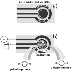
Usually, an electrochemical sensor is fabricated assembling a working electrode (e.g., carbon, graphite, platinum, gold), a reference (e.g., Ag/AgCl and calomel) and a counter electrode. In screen printed electrochemical sensor typology (see Figure 11a), electrodes are printed on a ceramic or plastic substrate, making them suitable for mass production, miniaturization and simple use. As described in Figure 11b, working electrode is the zone of the sensor where the recognition layer presents and electrochemical oxidation-reduction reactions happen.
Figure 10.A process flow chart of graphene synthesis. Reprinted with permission from [38].
In bottom-up approach, products are synthetized from smaller building blocks (Figure 10). Bottom-up methods encompass standard techniques including epitaxial growth using metallic substrates by means of chemical vapor deposition (CVD) or organic synthesis, which depends on the choice of precursor chemicals and thermal degradation and decomposition of the SiC [38,50]. 5. Electrochemical Sensors
A chemical sensor can be defined as a device that is able to respond reversibly and continuously to the surrounding environment, providing real-time and reliable information about its chemical composition. These sensors take advantage of a recognition part, which can be a chemical or biological element, joined with a transducing part, which provides an observable signal. Concerning electrochemical sensors, interaction between target(s) and recognition element(s) is converted to an electrical signal by which analytical information can be obtained.
Among different types of transducers that are applied in chemical sensors, e.g., optical, thermal, piezoelectric and so on, electrochemical transducers can offer advantages of low detection limits, wide linear response range, good stability and reproducibility in addition to simplicity, high sensitivity, miniaturization capability and low cost. Owing to these valuable advantages, electrochemical sensors have successfully found their way toward field applications and commercialization. Nowadays many useful electrochemical sensors can be found in the fields of clinical, environmental and industrial analyses [51,52].
Usually, an electrochemical sensor is fabricated assembling a working electrode (e.g., carbon, graphite, platinum, gold), a reference (e.g., Ag/AgCl and calomel) and a counter electrode. In screen printed electrochemical sensor typology (see Figure11a), electrodes are printed on a ceramic or plastic substrate, making them suitable for mass production, miniaturization and simple use. As described in Figure11b, working electrode is the zone of the sensor where the recognition layer presents and electrochemical oxidation-reduction reactions happen.
Nanomaterials 2017, 7, 406 11 of 33
Nanomaterials 2017, 7, 406 11 of 31
Figure 11. Screen printed electrochemical (SPE) sensor typology. (a) conventional SPE; (b) modified SPE. Working electrode where the electrochemical reactions happen and the electrical circuit connection are also shown.
Electrochemical sensors can be classified on the basis of the used recognition element:
Enzymatic electrochemical sensors: these sensors are often fabricated by immobilizing an enzyme layer on the surface of the working electrode, which responds to the interactions occurring due to the biocatalytic reactions in the presence of target substances. Enzymes, e.g., phosphatase, peroxidase, etc., are of the most regularly employed biological elements not only in the laboratory experiments but also even in the test kids which have recently found their way to the clinical market. In many cases, especially those exploited in biosensors, interaction of enzymes and targets involves some reduction and/or oxidation reactions, which can be easily converted to an electrical signal using electrochemical transducers. Using enzymes offers such advantages like high selectivity, because enzymes usually bind to their targets in a selective way, as well as high sensitivity and relatively fast response, because enzymes usually show catalytically activity by which sensitivity increases and response time decreases. However, losing activity due to immobilization, relatively high price and showing a loss of activity during a comparatively short time period are some limiting factors for using them.
Immunosensors: electrochemical immunoassay methods take advantage of high selectivity of the molecular recognition between the antigen and antibody. Due to its relatively simple device, high sensitivity and ability for miniaturization [53], electrochemical immunoassay has been continuously developed and applied in the field of disease biomarkers detection and other diagnostic tests like pregnancy test. Although immunosensors can be designed by immobilization of either antigens or antibodies, however, immobilization of antigen is more useful owning to this fact that, antibodies are more sensitive biological elements than antigens and immobilization process may lead to loss of affinity as a consequence of structural changing after immobilization [54,55].
Chemically modified electrochemical sensors: in these sensors, working electrode is chemically modified deliberately. Generally, electrode modification involves either coating or bounding of desired modifiers (onto electrode surface) that alters electrochemical features of the bare electrodes. Inclusion of electrocatalytic materials within the electrode matrix is another attractive approach for modifying electrodes. Inorganic, organic and hybrid composites can be used for modifying the composition of the electrode to meet specific sensing needs. In addition, these chemically modified electrodes can be used to anchor enzymes, antibodies, aptamers, where the interaction of the effective biorecognition layer with the electrode sensor surface is optimized, ensuring the highest dispersion and a better stability.
As regards the acquisition of the electrical signal, electrochemical sensors fall into three main categories, as follows:
Figure 11.Screen printed electrochemical (SPE) sensor typology. (a) conventional SPE; (b) modified SPE. Working electrode where the electrochemical reactions happen and the electrical circuit connection are also shown.
Electrochemical sensors can be classified on the basis of the used recognition element:
Enzymatic electrochemical sensors: these sensors are often fabricated by immobilizing an enzyme layer on the surface of the working electrode, which responds to the interactions occurring due to the biocatalytic reactions in the presence of target substances. Enzymes, e.g., phosphatase, peroxidase, etc., are of the most regularly employed biological elements not only in the laboratory experiments but also even in the test kids which have recently found their way to the clinical market. In many cases, especially those exploited in biosensors, interaction of enzymes and targets involves some reduction and/or oxidation reactions, which can be easily converted to an electrical signal using electrochemical transducers. Using enzymes offers such advantages like high selectivity, because enzymes usually bind to their targets in a selective way, as well as high sensitivity and relatively fast response, because enzymes usually show catalytically activity by which sensitivity increases and response time decreases. However, losing activity due to immobilization, relatively high price and showing a loss of activity during a comparatively short time period are some limiting factors for using them.
Immunosensors: electrochemical immunoassay methods take advantage of high selectivity of the molecular recognition between the antigen and antibody. Due to its relatively simple device, high sensitivity and ability for miniaturization [53], electrochemical immunoassay has been continuously developed and applied in the field of disease biomarkers detection and other diagnostic tests like pregnancy test. Although immunosensors can be designed by immobilization of either antigens or antibodies, however, immobilization of antigen is more useful owning to this fact that, antibodies are more sensitive biological elements than antigens and immobilization process may lead to loss of affinity as a consequence of structural changing after immobilization [54,55].
Chemically modified electrochemical sensors: in these sensors, working electrode is chemically modified deliberately. Generally, electrode modification involves either coating or bounding of desired modifiers (onto electrode surface) that alters electrochemical features of the bare electrodes. Inclusion of electrocatalytic materials within the electrode matrix is another attractive approach for modifying electrodes. Inorganic, organic and hybrid composites can be used for modifying the composition of the electrode to meet specific sensing needs. In addition, these chemically modified electrodes can be used to anchor enzymes, antibodies, aptamers, where the interaction of the effective biorecognition layer with the electrode sensor surface is optimized, ensuring the highest dispersion and a better stability.
As regards the acquisition of the electrical signal, electrochemical sensors fall into three main categories, as follows:
Nanomaterials 2017, 7, 406 12 of 33
Potentiometric sensors: In these kinds of sensors, a potential was established at the surface of recognition part, which is proportional to activity of analyte in a logarithmic fashion. Measured emf at zero current is used as an index for determination of the substance which is being determined. Two kinds of potentiometric sensors i.e., ion selective electrodes and field effect transistors are mostly used for constructing these kinds of sensors. In both of aforementioned potentiometric sensors, a permselective recognition part plays vital role by creating a potential signal that is primarily related to the target ion. Although potentiometric sensors show advantages like simplicity, selectivity, potential capability for multi-elemental analyses in array arrangement and low cost, they usually suffer from less sensitivity and slower response time than their voltammetric counterparts.
Voltammetric sensors: these sensors work based on applying a decreasing, increasing or constant potential between working and reference electrodes until reduction or oxidation of analyte(s) occurs and a sharp change in current is appeared. These current changes attributed directly to the concentration of analyte in some conditions. Knowing the oxidation or reduction peak of analyte, one can step the potential to about that value and pursues the current. This method is named amperometry. In all voltammetric methods, electron transfer between electrode and analyte is the key step. Many efforts have been made for modification of electrode surface in order to increase the rate of electron transfer between analyte and electrode and/or hinder this electron transfer for interference species during measurements.
Electrochemical impedance spectroscopy (EIS): this powerful technique has found its way to electrochemical sensors field since last decades and has well proved its ability to provide some valuable information both quantitatively and qualitatively. In this technique, an alternating voltage is often applied and alternating current response will be analyzed with respect to frequency. Two or three electrodes configurations well as frequency response analyzer (FRA) and potentiostat are necessary to perform an EIS measurement [56,57]. Superimposing a constant voltage on alternating voltage is a frequently used strategy during EIS measurements. However, it is necessary to use the lowest possible amplitude for this direct voltage, most often in the range of mV, to avoid of none linearity in the under-study system. According to the apparatus, it is possible to cover a vast range of frequencies, usually from few millihertz to some megaHertz, during EIS and thereby extract some valuable information about under study system [58,59].
6. Application
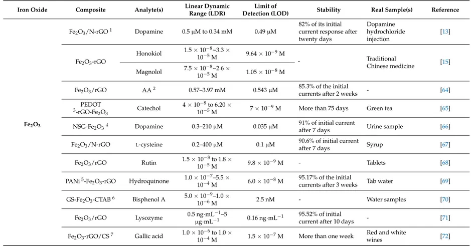
Unique features of IONs e.g., strong magnetic properties, low toxicity, high adsorption ability for immobilization of desired biomolecules and good biocompatibility, together with elegant properties of this new comer member of carbon family e.g., high electrical/thermal conductivity, large surface area and electrocatalytic properties, have stimulated many interests for overcoming difficulties in realizing new scientific ideas or improving the performance of many current devices and methods [60–62]. In this review, we will put our particular focus just on application of graphene-IONs in biochemical determination. Catalytic activity of the graphene-IONs can be improved due to enhanced electronic communication e.g., charge transfer between catalyst and support. Additionally, synergistic effects of graphene sheets and IONs components provide nanocomposite with novel physicochemical properties and consequently enhance electrochemical performance. As a result, graphene-IONs nanocomposites have been considered as one of the most promising hybrid materials that can boost the development of more efficient electrochemical sensors [63]. This part is divided into six sections, where each section is related to a single analyte or a group of analytes determined by the graphene-IONs nanocomposites sensors. Table2summarizes published papers so far in which graphene-IONs composites are used for the fabrication of the electrochemical sensors.
Nanomaterials 2017, 7, 406 13 of 33
Table 2.Application of IONs-graphene composite in biochemical determination.
Iron Oxide Composite Analyte(s) Linear Dynamic
Range (LDR)
Limit of
Detection (LOD) Stability Real Sample(s) Reference
Fe2O3
Fe2O3/N-rGO1 Dopamine 0.5 µM to 0.34 mM 0.49 µM
82% of its initial current response after twenty days Dopamine hydrochloride injection [13] Fe2O3-rGO Honokiol 1.5 × 10⁻⁸~3.3 × 10⁻⁵M 9.64 × 10 −9M - Traditional Chinese medicine [15] Magnolol 7.5 × 10⁻⁸~2.6 × 10⁻⁵M 1.05 × 10⁻⁸M
Fe2O3/rGO AA2 0.57–3.97 mM 0.543 µM 85.3% of the initial
currents after 2 weeks - [64]
PEDOT
3-rGO-Fe
2O3 Catechol
4 × 10⁻⁸to 6.20 ×
10−5M 7 × 10⁻⁹M More than 75 days Green tea [65]
NSG-Fe2O34 Dopamine 0.3–210 µM 0.035 µM 91% of initial currentafter 7 days Urine sample [66]
Fe2O3/N-rGO L-cysteine 0.2–400 µM 0.1 µM 90.6% of initial current
after 7 days Syrup [67]
Fe2O3/rGO Rutin 1.5 × 10 −8to 1.8 × 10⁻⁵M 9.8 × 10 −9M - Tablets [68] PANi5-Fe 2O3-rGO Hydroquinone 1.0 × 10 −7–5.5 × 10⁻⁴M 6.0 × 10 −8M 95.17% of the initial
currents after 3 weeks Tab water [69] GS-Fe2O3-CTAB6 Bisphenol A 5.0 × 10
−9–1.0 × 10⁻⁶M 2.5 nM - Water samples [70] Fe2O3/rGO Lysozyme 0.5 ng·mL −1–5 µg·mL−1 0.16 ng·mL −1 95.52% of initial
current after 10 days - [71]
Fe2O3-rGO/CS7 Gallic acid 1.0 × 10
−6to 1.0 ×
10−4M 1.5 × 10⁻⁷M More than one week
Red and white
Nanomaterials 2017, 7, 406 14 of 33
Table 2. Cont.
Iron Oxide Composite Analyte(s) Linear Dynamic
Range (LDR)
Limit of
Detection (LOD) Stability Real Sample(s) Reference
Fe3O4
AuNPs/MrGO8 Cortisol 0.1 to 1000 ng/mL 0.05 ng/mL 90.16% of initial
current after 20 days Human serum [73] Fe3O4-rGO/nafion Lobetyolin 1.0 × 10
−7–1.0 ×
10−4M 4.3 × 10⁻⁸M
93.62% of initial
current after 14 days Radix Codonopsis [74] H-Fe3O4@C/GNS9
Dopamine 0.1 to 150 µM 0.053 µM
More than 15 days Rat brain tissue
and urine [75]
Uric acid 1.0 to 100 µM 0.41 µM
(Fe3O4/rGO) and
MIL@MIP10 Methamidophos and Omethoate 1.0 × 10⁻⁷–1.0 × 10⁻¹²M and 1.0×10⁻⁷–1.0×10⁻¹³ M 2.67 × 10⁻¹³M and 2.05 × 10⁻¹⁴ M 94.5% of initial current after 15 days Cucumber and kidney bean samples [76]
Fe3O4-GO PSA and PSMA11
1.25–1000 pg/mL and 9.7–5000 pg/mL 1.25 pg/mL and 9.7 pg/mL 80% of initial current after 4 days Prostate cancer patient serum samples [77]12
Fe3O4-rGO Glucose 0.05 to 1 mM 0.1 µM 95.6% of initial currentafter one month - [78]
Fe3O4-SiO2/GO Uric acid 0.5 to 250.0 µM 0.07 µM - Urine sample [79]
GS-Fe3O4/Au@Ag13 CEA14 0.1 pg/mL to 100ng/mL 0.0697 pg/mL More than 2 weeks Human serumsamples [80]
AuM/N-rGO15 Leukemia cancer cells
10 to 1 × 10⁶cell
mL−1 10 cell mL
−1 - Human blood
plasma [81]
CB/Fe3O4-GO16 Chlorpyrifos 0.1–105 ng/mL 0.033 ng/mL 91.2% of initial currentafter 20 days Leafy vegetable [82]
Fe3O4@SiO2/GO Methyldopa (MD) 0.1–400.0 µM 86.0 nM - MD tablet andurine samples [83]
Fe3O4-rGO Sulfonamide 5 × 10 −7~1.1 ×
10−4M 5.0 × 10
−8M [84]
Fe3O4-GO/carbon
nanotube Salicylic acid 5.00 to 155 µM 900 nM - Water sample [85]
magnetic
Nanomaterials 2017, 7, 406 15 of 33
Table 2. Cont.
Iron Oxide Composite Analyte(s) Linear Dynamic
Range (LDR)
Limit of
Detection (LOD) Stability Real Sample(s) Reference
Fe3O4 Nafion/Mb-SA-Fe3O4-GR/ CILE18 Trichloroacetic acid 1.4 to 119.4 mM 0.174 mM - - [87] 3D NG-Fe3O4 DNA 1.0 × 10 −14to 1.0
× 10−6M 3.63 × 10⁻¹⁵M 90% of initial currentafter 2 weeks Serum samples [88]
Fe3O4-SnO2-Gr
AA 0.1 to 23.00 µM 62.0 nM
More than 4 weeks
Biological fluids—pharmaceutical samples [89] DA 0.02 to 2.8 µM 7.1 nM UA 0.015 to 2.40 µM 5.0 nM Fe3O4@GQD/ f-MWCNTs Progesterone 0.01–0.5 and 0.5–3.0 µM 2.18 nM 85% of initial current after 6 weeks Serum samples—pharmaceutical products [90]
Alginate/Fe3O4-rGO Tetracycline 1 nM to 5 µM 0.6 nM 95.86% of initialcurrent after 2 weeks
Food,
environmental and clinical samples
[91] TSA-doped
PPy/Fe3O4/rGO Dopamine 7.0–2.0 µM 2.33 nM More than 10 days
Urine and serum
samples [92]
Pt-Fe3O4/rGO Cysteine 0.10 to 1.0 mM 10 µM More than 2 weeks - [93]
Fe3O4-rGO Chlorpyrifos 0.05 to 100 µg/L 0.02 µg/L - Vegetable samples [94]
PS/Fe3O4 -GO-SO3H19 Doxorubicin 4.3×10⁻⁸to 3.5×10⁻⁶M 4.9 nM, 14 nM and 4.3 nM -Plasma, cerebrospinal fluid, urine [95] 8.6×10⁻⁷to 13×10−6M 2.6×10⁻⁸to 3.5×10⁻⁶M
Pt/Fe3O4/rGO NADH20 0.03–1.5 nM 5 nM - - [96]
Fe3O4-rGO Dopamine 0.010 and0.270 µM 5 nM 93.5% of initial currentafter 30 days Urine sample [97]
GO/CS-Fc21 CEA22 0.001–30 ng·mL−1 0.39 pg - Human serum [98]
ILFSGo23 Ascorbic acid 1.0 × 10⁻⁶to
9.0×10⁻⁴M 2.3 × 10
Nanomaterials 2017, 7, 406 16 of 33
Table 2. Cont.
Iron Oxide Composite Analyte(s) Linear Dynamic
Range (LDR)
Limit of
Detection (LOD) Stability Real Sample(s) Reference
Fe3O4 Fe3O4-rGO Nitrofuranzone 1.0 × 10⁻⁵to 1.09×10⁻⁴M 2.92 × 10 −7M - - [100] Semicarbazide 1.0 × 10⁻⁶to 1.09×10⁻⁴M 6.17 × 10 −7M Fe3O4-Co3O4/rGO Dopamine 5 × 10 −7to 1.55×10⁻³M 1.3 × 10⁻⁷M
More than 2 weeks Human serumsamples [101] Uric acid 1.5 × 10⁻⁶to 1.6 × 10⁻³M 1.8 × 10 −7M rGO/AuNP/Ab2/ S/IMB24 Salmonella pullorum 102 to 106
CFU·mL−1 89 CFU·mL−1 - Chicken liver [102]
GQD-Fe3O4/
CNT25 L-DOPA 3.0 to 400 µM 14.3 nM - Seeds and fava bean [103]
Fe3O4-rGO
Adenine 0.05–25 µM 4 nM
More than 20 days
Fish, urine samples
and vitamin B4 tablet [104]
Guanine 0.05–25 µM 3 nM
Fe3O4@ZIF-8
26/RGO Dopamine 2.0 × 10
−9to 1.0 ×
10−5M 6.67 × 10
−10M More than 10 days Urine and serum
samples [105]
Pd–Fe3O4-GS immunoglobulinG 5 × 10 −6to 5
ng/mL 3.2 fg/mL More than one month
Human serum
samples [106]
Fe3O4-GO/MIP27 interleukin-8 0.1 to 10 pM 0.04 pM 92.9% of initial currentafter 1 month Saliva [107]
Fe3O4-GO@
AuNPs-MIP Dibutyl phthalate
2.5 × 10⁻⁹to 5.0 ×
10−6M 8×10⁻¹⁰M
96.3% of initial current
after 4 weeks Drink samples [108]
AuNPs/Fe3O4
-APTES28-GO
Catechol 2–145 µM 0.8 µM 90% of initial current
after 5 days Tap water [109]
Hydroquinone 3–137 µM 1.1 µM
MGLA29 APOA2 protein30 0.19 to 1.95
µg·mL−1 6.7 pg·mL−1
About 80% decrease
after one week Human urine [110]
DPSPP 31/rGO/Fe 3O4 Hydrazine 120.0–600.0 nM 40.0 nM - Water samples [111] Hydroxylamine 10–155.0 µM 3.4 µM rGO/Fe3O4 Melatonin 0.02–5.80 µM 8.40 × 10⁻⁶M - Pharmaceutical and biological fluids [112] Dopamine 0.02–5.80 µM 6.50 × 10⁻⁶M
Nanomaterials 2017, 7, 406 17 of 33
Table 2. Cont.
Iron Oxide Composite Analyte(s) Linear Dynamic
Range (LDR)
Limit of
Detection (LOD) Stability Real Sample(s) Reference
Fe3O4 GS-Nf 32/Au-Fe 3O4 Clenbuterol 0.5 ng·mL−1to 200 ng·mL−1 0.22 ng/mL 92% of initial current
after 4 weeks Pork sample [113]
GS-Au-Fe3O4 146 antigen(CD146) 5 pg·mL −1to 500
ng·mL−1 2.5 pg·mL
−1 More than 2 months Human serum
samples [114] rGO/Fe3O4 Ascorbic acid 1–9 mM 0.42 µM - - [115] Dopamine 0.5–100 µM 0.12 µM CS-Fe3O4-GO
Hydroquinone 1.5 to 150 µM 20 nM 95% of initial current
after 2 weeks Tap water [116]
Catechol 1 to 410 µM 250 nM
GS-Nf/Au-Fe3O4 chloramphenicol 2.0 ng/mL to 200.0ng/mL 0.82 ng/mL 93.2% of initial currentafter one month Milk sample [117]
Fe3O4-GO-SO3H Furosemide 20–100 µM (serum) 0.1 µM 92.5% of initial current
after 20 days
Human serum and
urine [118] 18–720 µM (Urine) 0.11 µM Iron/nickel oxide nanoparticles-graphene Orange II 5.0 Nm–3.0 µM
2.0 nM (for all) - Different kinds of
food samples [119]
Allura red and Amaranth
5.0 nM–10.0 µM and 5.0 nM–5.0 µM
rGO/Fe3O4 N-acetylcysteine 0.10–10.0 mM 11.1 mM 93.8% of initial currentafter 2 weeks - [120]
rGO/Fe3O4 Sudan I 0.008 µM to 6 µM 0.5 nM - Food samples [121]
Multi-functionalized magnetic graphene sphere Thyroxine 0.05 pg·mL −1to 5 ng·mL−1 15 fg·mL−1 85.3% of initial current after 20 days - [122] Gr-chitosan/Fe3O4 Guanosine 2.0 × 10 −6to 3.5 × 10⁻⁴M 7.5 × 10⁻⁷M 90.75% of initial current after 15 days
Urine samples and traditional Chinese medicines
[123]
1 Fe
2O3/nitrogen-doped Rgo; 2 Ascorbic Acid; 3 Poly (3,4-ethylenedioxythiophene); 4 Nitrogen and sulfur dual doped graphene supported Fe2O3; 5 Polyaniline; 6Hexadecyltrimethylammonium bromide;7Chitosan;8Gold nanoparticles-magnetic functionalized reduced graphene oxide;9Carbon-encapsulated hollow Fe
3o4/GO nanosheets; 10MIL@MIP film as recognition element;11Prostate specific antigen And prostate specific membrane antigen;12LDR and LOD were tunable;13Magnetic graphene loaded gold
and silver core-shell nanoparticles;14Carcinoembryonic antigen;15Gold-coated magnetic nanoparticles on a nitrogen-doped graphene;16Carbon black (CB) and graphene oxide@
Fe3o4;17Indium gallium zinc oxide;18Myoglobin (Mb), sodium alginate (SA)-Fe3O4-GR composite on the carbon ionic liquid electrode;19Magnetic graphene oxide grafted with
chlorosulfonic acid (Fe3O4-GO-SO3H) in the presence of polystyrene;20Dihydronicotinamide adenine dinucleotide;21Graphene oxide/chitosan-ferrocene;22Carcinoembryonic
antigen;23Ionic liquid-magnetic core-shell Fe
3O4@SiO2/graphene oxide;24Immunomagnetic beads;25Immunomagnetic beads;26Zeolitic imidazolate framework-;27Molecularly
imprinted polymer;28(3-Aminopropyl) triethoxysilane;29Magnetic graphene with longchain acid groups;30Apolipoprotein A II protein;311-[2,4-Dihydroxy-5-(phenylazo-4-sulphonic acid)phenyl]-1-phenylmethanon;32Graphene sheets (GS)-Nafion (Nf) film.
![Figure 1. Crystal structures of (a) hematite and (b) magnetite. Reproduced with permission from [3]](https://thumb-eu.123doks.com/thumbv2/123dokorg/4597813.39560/2.892.249.651.802.1031/figure-crystal-structures-hematite-b-magnetite-reproduced-permission.webp)
![Figure 10. A process flow chart of graphene synthesis. Reprinted with permission from [38].](https://thumb-eu.123doks.com/thumbv2/123dokorg/4597813.39560/10.892.123.772.314.545/figure-process-flow-chart-graphene-synthesis-reprinted-permission.webp)