UNIVERSITY OF ROME “TOR VERGATA”
Dr. Alessandra Di Blasi
PhD Course in “Materials for Environment and Energy”
(XIX cycle)
Low Temperature DMFCs
for Portable Applications
Tutor Coordinator
Dr. Vincenzo Antonucci Prof. Enrico Traversa
TABLE OF CONTENTS
S
UMMARY3
CHAPERT
I – Preliminary Remarks
5
I.1 – Introduction to Fuel Cell System
5
I.2 – Fundamental Aspects
7
I.2.1 – Introduction to DMFCs
7
I.2.2– DMFC performance
8
I.2.3 – Structural effect and electrode-kinetics
11
I.2.4 – Pt-Ru binary alloy electrocatalysts
13
I.2.5 – Experimental methods
14
I.3 – Morphological aspects of electrocatalysts
18
I.3.1 – Role of surface area and metal loading
18
I.3.2 – Role of carbon support
19
I.3.3 – Preparation methods
20
I.4 – Cathodic reduction of oxygen
21
I.4.1 – General considerations
21
I.4.2 – Oxygen electroreduction in DMFCs
22
I.4.3 – Carbon supported electrocatalysts
24
I.5 – References
27
CHAPTER
II – Influence of Catalyst Utilization on the
Electrochemical Behaviour of Low Temperature DMFC
31
II– Introduction
31
II.1 – Experimental
31
II.2 – Results and Discussion
32
II.2.1 – Physico-chemical characterization
32
II.2.2 – Electrochemical characterization
34
II.3 – Conclusions
43
CHAPTER III – Investigation of Pt-M / C as DMFC
Cathode Catalysts
45
III – Introduction
45
III.1 – Experimental
47
III.2 – Results and Discussion
48
III.2.1 – Physico-chemical analysis
48
III.2.2 – Electrochemical characterization
51
III.2.3 – Influence of ionomer loading 54
III.3 – Conclusions
57
III.4 – References
59
CHAPTER IV – Rotating Disc Analysis of Oxygen Reduction at Pf-Fe
Catalyst for Low Temperature Direct Methanol Fuel Cells 61
IV.1 – Introduction
61
IV.2 – Results and Discussion
62
IV.3 – Conclusions
68
IV.4 – References
69
CHAPTER V – Optimization of Electrode Properties for Low
Temperature DMFC Applications
70
Cathode Catalysts
V – Introduction
70
V.1 – Experimental
71
V.2 – Results and Discussion
72
V.3 – Conclusions
81
V.4 – References
82
S
UMMARY
Technological improvements in direct methanol fuel cells (DMFCs) are promoted by their exciting perspectives of application in portable, transportation and stationary devices. Direct Methanol Fuel Cells were in the past mainly designed for relatively high
temperature (>90°C) operation in order to enhance the methanol electro-oxidation
kinetics and to increase the ionic conductivity of the polymeric membrane. New composite membranes have been developed to further extend the operating temperature up to 150°C. High operating temperatures are especially favourable for transportation applications. However, the most promising short term application of DMFC appears now to involve the field of portable power sources[1-4] where they can suitably to replace or support batteries. In this regard, increasing interest is devoted towards the miniaturisation of these fuel cell devices in order to replace the current Li-ion batteries. Theoretically, methanol has a superior specific energy density (6000 Wh/kg) in comparison with the best rechargeable battery, lithium polymer and lithium ion polymer (600 Wh/kg) systems. This advantage translates into much longer conversation times using mobile phones, longer time of continuous operation for laptop computers and more power available on these devices to support consumer demand. In relation to consumer convenience, another significant advantage of the DMFC over the rechargeable battery is its potential for instantaneous refuelling. Unlike rechargeable batteries that require hours for charging a depleted power pack, a DMFC can have its fuel replaced in minutes. These significant advantages make DMFC a promising device in the portable electronic market [5-7].
The research activity of this thesis is addressed towards the development of low temperature (30-60°C) DMFCs for portable applications. The different working conditions of portable system i.e. passive operation mode, air breathing etc., introduce new issues with respect to DMFCs operating at high temperatures; thus development of a system for portable applications requires further efforts.
In this thesis, three fundamental aspects have been mainly addressed, these are:
I. Pt loading: analysis of the influence of the Pt loading on the electrochemical behaviour of a DMFC;
II. Methanol tolerant cathode catalysts: analysis of the catalytic activity for the oxygen reduction reaction in DMFC for Pt alloy with transition metals;
IV. Passive mode operation.
The aim of the present work is to contribute to the comprehension of the main issues associated to the low DMFC operation temperature. Such an investigation was carried out by using both physico-chemical and electrochemical methods. Specific tests were carried out by using diagnostic techniques in order to individuate potential solutions to drawbacks affecting DMFCs.
CHAPTER
I
P
RELIMINARYR
EMARKSI.1
I
NTRODUCTION TOF
UELC
ELLS
YSTEMMost of the world energy requirements are presently addressed by burning fossil fuel in low efficiency thermal processes. An increasing use of renewable energy sources is necessary to reduce environmental issues such as atmospheric pollution, global warming, green house effect. Besides, renewable energy sources, alternative energy conversion technologies with high efficiency are required. Fuel cells represent a potential solution both in stationary and transportation applications due to their low environmental impact and high conversion efficiency. Fuel cells do not utilize a thermodynamic cycle as opposite of internal combustion engine (ICE). In fact, they convert the chemical energy of a reaction directly into electrical energy. The basic physical structure or building block of a fuel cell consists of an electrolyte layer in contact with a porous anode and cathode on each side. The electrolyte is an ion exchange membrane (fluorinated sulfonic acid polymer or other similar polymers) that is an excellent proton conductor. The typical protonic membrane, e.g. Nafion, plays both the role of an acid medium and of separator between the two electrode compartments. The electrons liberated at the anode by the oxidation of methanol circulate in the external electrical circuit, producing electrical energy, and reach the cathode where they reduce the oxidant, usually oxygen from air. Thus, in a fuel cell there is no direct contact between fuel and oxidant. Therefore, the overall reaction corresponds to the catalytic combustion of the fuel with oxygen.
As well known, the thermal efficiency of a practical machine is always less than 100%. The internal combustion engine efficiency is about 18%, while the typical efficiency of most fuel cells is about 40%. The energy balance of a fuel cell is based on the input chemical and output electrical energy and heat. The energy balance varies for the different types of cells because of the difference in reactions that occur and the operating temperature. In general, the cell energy balance states that the enthalpy flow of the reactants entering the cell will equal to the enthalpy flow of the products leaving the cell plus the sum of four terms: 1) the net heat generated by physical and chemical processes within the cell, 2) the dc power output from the cell, 3) the rate of heat loss from the cell
to its surroundings, 4) the energy required by the auxiliaries e.g. pumps, blowers, compressors.
The ideal thermal efficiency of an energy conversion device defined as the ratio of the amount of useful energy that, in the ideal case of a fuel cell, is the change in Gibbs free
energy of a reaction to the enthalpy (∆H) of the reaction. Thus, the thermal efficiency of
an ideal fuel cell operating reversibly on a specific fuel and oxygen at standard conditions is: H G ideal ∆ ∆ = η (1)
Whereas, the thermal efficiency of an actual fuel cell, operating at a cell voltage (Vcell),
is given by: aux f E E H G η η η ∗ ∗ ∆ ∆ ∗ ∆ ∆ = ° → electricalefficincy E E =η ∆ ∆ ° (2)
η=ηideal∗ηelectricalefficincy∗ηf ∗ηaux (3)
Fuel utilization, ηf , takes into account the excess of fuel fed to the cell with respect to
the stoichiometry amount required to achieve the operating current (Faraday Law). Since
in the DMFC, a significant part of fuel is lost in the cross-over process (Ie q), the fuel
efficiency is defined as:
I I I eq f = + η (4) aux
η refers to the power consumption of the auxiliaries.
In the power consumed by auxiliaries (blower, pumps, ect.) is not negligible, it must be also taken into account in the evaluation of efficiency.
powerout electrical ry forauxilia powerinput electrical powerout electrical aux netW W netW + = η = ced powerprodu electrical powerout electrical W netW (5) Fuel cells result more advantageous both in terms of fuel utilization and lower environmental impact than ICE:
• H2-based FCs avoid air pollution coming from fossil fuel combustion;
• FCs do not utilize sulphur containing fuel;
However, there are significant difficulties for market application; this is due to both high costs of materials used in fabricating (noble metal catalysts, perfluosulfonic membranes) and the cost of hardware manufacturing (MEAs) which are presently higher than conventional energy conversion system.
Fuel cells include different kind of devices having different working conditions and final applications. They can be classified by use of diverse categories, depending on the
combination of type of fuel and oxidant (H2, CH3OH, CH4 ect.), whether the fuel is
processed outside (external reforming) or inside (internal reforming) the fuel cell, the type of electrolyte, the temperature of operation, whether the reactants are fed to the cell by internal or external manifolds, etc. The most common classification of fuel cells is by the type of electrolyte used in the cells and includes 1) alkaline fuel cell (AFC), 2) phosphoric acid fuel cell (PAFC), 3) molten carbonate fuel cell (MCFC), 4) intermediate temperature solid oxide fuel cell (ITSOFC), and 5) tubular solid oxide fuel cell (TSOFC) and polymer electrolyte fuel cell (PEFC). These fuel cells are listed in the order of approximate operating temperature, ranging from ~100°C for AFC, ~200°C for PAFC, ~650°C for MCFC, ~800°C for ITSOFC, 1000°C for TSOFC and ~80- 130°C for polymer electrolyte fuel cell (PEFC). The operating temperature and useful life of a fuel cell are determined by the physicochemical and thermo-mechanical properties of materials used in the cell components (i.e., electrodes, electrolyte, interconnect, current collector, etc.).
I.2
F
UNDAMENTALA
SPECTSI.2.1INTRODUCTION TO DMFCS
Direct Methanol Fuel Cells (DMFCs) are promising power sources for a range of applications including transportation, portable power sources and distributed generation of clean energy. For the methanol reaction the overall reaction corresponds to the catalytic combustion of methanol with oxygen.
Thernodynamics of direct methanol fuel cell:
Anode reaction: CH3OH + H2O → CO2 + 6 H+ + 6 e- (6) cathode reaction: 3/2O2 + 6e- + 6 H+ → 3 H2O (7) Overall reaction: CH3OH + 3/2 O2 → CO2 + 2 H2O (8)
The free energy and the electromotive force associated with the overal reaction at 25°C and 1 atm are:
1 3 686 − − = ∆GCH OH kJmol ; ∆VCH3OH =1.18V
The thermal efficiency of an ideal fuel cell, operating reversibly on methanol and oxygen at standard condition, is given by:
form OH CH ideal H G ∆ ∆ = 3 η (9) where: 1 3 724.3 − = ∆ − ∆ =
∆HformCH OH Hprod Hreag kJmol (10)
947 . 0 3 . 724 686 1 1 = − − = − − kJmol kJmol ideal η (11) I.2.2DMFC PERFORMANCE
Methanol is an attractive fuel because it is a liquid under atmospheric conditions, hence its storage and transportation is less complicated than hydrogen, and it could be supplied through the existing gasoline infrastructure. Despite of these advantages, major obstacles to their commercial application are:
• slow methanol electro-oxidation and oxygen reduction on the electrodes surface
and the complicate diffusion processes of the reactants/products;
• dehydration of the electrolyte working at temperature higher than 120°C;
• water flooding due to the liquid fed to anode side. If there is too much
humidification the electrode floods which causes problems with mass transport of the gas to the electrode;
• cross-over of methanol through the electrolyte membrane from the anode to the
cathode;
• poisoning of the cathode surface in the presence of methanol cross-over.
Methanol cross-over is an issue that affects cathode performance [8]. Wang et al. [9] found that methanol is oxidized heterogeneously in the presence of oxygen and suitable catalyst leading to a so-called “mixed potential” effect, and that the cathode is additionally poisoned by methanol. The impact of methanol cross-over on the current -voltage-characteristics of prototype DMFCs was investigated in numerous studies [10,11,12,13].
Two options exist to overcome cathode performance losses due to methanol cross-over: i) polymer electrolyte membranes have to be used which allow less methanol permeation, or ii) a cathode catalyst, which neither promotes heterogeneous oxidation of methanol nor methanol poisoning, has to be found [14]. These drawbacks affect cell performance as it is possible to observe in the following scheme, applicable to all fuel cells:
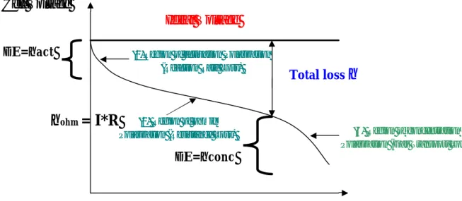
Fig. I-1 Ideal and actual fuel cell voltage/current characteristic
Useful work is obtained (∆G= -nFE) from fuel cell a reasonable current is drawn, but
the actual cell potential is decreased from its equilibrium potential because of irreversible losses, as shown in Figure 1. The losses, which are called polarization, overpotential or
over-voltage (η), originate primarily from three sources: (1) activation polarization (act), (2)
ohmic polarization (ohm), and (3) concentration polarization (conc) [15]. These losses result in a cell voltage (V) less than the ideal potential, E (V = E – Losses).
Activation polarization: activation polarization is present when the rate of an
electrochemical reaction at an electrode surface is controlled by sluggish electrode kinetics. It is possible to study the catalytic activity in this region since a concentration gradient
(Cs=Cb). In other words, this region is directly related to the rates of electrochemical
reactions. Thus, reactants have to overcome an activation barrier.
Current density represents the reaction rate, a small current is associated to a slow
reaction rate of methanol oxidized to CO2. A part of the methanol that does not react will
pass through the membrane reaching the cathode compartment, where a mixed potential Current density (mA/cm2)
Cell Voltage
Total loss
η
Ideal Voltage
(2) Region of ohmic Polarization (Resistance Loss)
(1)Region of activation Polarization (Reaction Rate Loss)
(3) Region of concentration Polarization (Gas Transport Loss)
∆E=ηact
∆E=ηconc
η
ohm= I*R
will form in the presence of oxygen. The activation polarization can be described by the Tafel equation:
∆E = ηact= (RT/αnF) ln (i/io) (12)
or
ηact= a+b log i (13)
Where
a= -2.3RT/αnF log i0
b= -2.3RT/αnF
i0 is an important kinetic characteristic of an electron transfer process, called exchange
current density.
Ohmic polarization: the resistance to flow of ions in the electrolyte and resistance to
flow of electrons through the electrode materials determine ohmic losses. The dominant ohmic losses, through the electrolyte, are reduced by decreasing the electrode separation and enhancing the ionic conductivity of the electrolyte. Because both the electrolyte and fuel cell electrodes obey to Ohm's law, the ohmic losses can be expressed by the equation:
ηohm = I∗R
Concentration polarization: when the reaction is running the reactants react
immediately on the electrodes surface (Cs=0). It is important to have a good diffusion rate
of the reactants on the catalyst pores and, a good diffusion rate of the products from
internal pores. Otherwise, a significant concentration gradient will form, whit Cs<Cb.
The reaction rate in this case will be a function of reactants/products flow from reaction sites. There is an inside and outside diffusional control.
This concentration gradient causes an over potential or a potential drop (∆E) that is
recorded as a potential drop:
∆E=ηconc= RT/nF ln (Cs/Cb) (14)
If
Cs=Cb→ ηconc=0 (15)
Cs/Cb=(1-i/il) (16)
∆E=ηconc= RT/nF ln 1-i/il (17)
These losses have to be subtracted from the ideal potential (E):
Veff = Ec - Ea - ηact - ηc- IR (18)
where
Veff= effective cell potential.
All these aspects lead to a low efficiency and reduced power density performance
especially for a DMFC.Thus, the main objectives for Direct Methanol Fuel Cell are:
• to decrease the over voltages and hence to increase the reaction rate both at
the anode and at the cathode;
• to increase the reaction selectivity towards complete oxidation to CO2;
• to find methanol tolerant oxygen cathodes;
• to decrease the effects of methanol cross-over through the ionic membrane
by developing advanced membranes with optimum structures and compositions.
I.2.3 STRUCTURAL EFFECTSAND ELECTRODE-KINETICS
The electrocatalytic oxidation of methanol has been thoroughly investigated during the last three decades, particularly in regard to the possible development of DMFCs [16-19]. The oxidation of methanol (the electrocatalytic reaction) is constituted of several steps, which involve adsorbed species. From a general point of view, almost all electro-oxidation
reactions involving low molecular weight organic molecules, such as CO, CH3OH,
C2H5OH, HCOOH and HCHO, are enhanced by the presence of a Pt-based catalyst
[20-23] at least in acidic environment. Determination of the mechanisms for this reaction needs specific information on:
1. the electrode kinetics for the formation of partially oxidized products;
2. the nature and the distribution of adsorbed intermediates at the electrode surface. The quantitative analyses of reaction products, due to partial or complete oxidation, can be performed by different methods. Apart from a decrease in the Coulombic efficiency, the formation of partially oxidized products can be deleterious for the DMFC application, because some of these may act as poisoning species for the electrode.
The mechanism, by which such synergistic promotion of the methanol oxidation reaction brought about, has been the subject of numerous studies during the last 30-40
years, in which various spectroscopic methods have been employed in conjuction with electrochemistry [6-10]. A combination of cyclic voltammetry [24-29], in situ ellipsometry [30], X-ray absorption spectroscopy [31], on-line mass spectrometry and in-situ FTIR spectroscopic studies [32-37], revealed that the electro-oxidation of methanol on Pt-based catalysts proceeds through the mechanism (sequence of non-elementary reaction steps) below described. First a sequence of dehydrogenation steps give rise to adsorbed methanolic residues, according to the following scheme:
Pt + CH3OH → Pt-(•CH3OH) (19)
Pt-(•CH3OH) → Pt-(•CH2OH)ads + H+ +
e
- (20)Pt-(•CH2OH)ads → Pt-(•CHOH)ads + H+ +
e
- (21)Pt-(•CHOH)ads → Pt-(•CHO)ads + H+ +
e
- (22)Formyl like species (•CHO)ads has been identied, by IR (absorption band at around 1690 cm-1) [38]. After the reaction (22), the formyl like species is spontaneously dissociated on platinum according to the reaction;
Pt-(
•
CHO)
ads→
Pt-(
•
CO)
ads+ H
aq++ e
-(23)
The strongly adsorbed CO species was identified as the main poisonig species blocking the electrode active sites for further adsorption of intermediates formed during methanol oxidation [39].
Reaction represented by Eq. (23) is a rather fast process and it is the main reason for the CO poisoning of platinum surface. The configuration of the adsorbed CO species depends on the electrode coverage and on the electrode structure. On a smooth platinum polycrystalline electrode, linearly-bonded CO is the main species at intermediate to high coverage, wherease bridge and multibonded CO are clearly seen at low coverage. Linearly-bond CO is the main species adsorbed on Pt (110), wherease multiLinearly-bonded CO is mainly formed on Pt (111) [40].
The vital step in the reaction mechanism appears to be the formation of the
intermediate
(
•
CHO)
ads , which facilitates the overall reaction. The kinetics of its furtherdesorption and/or oxidation into reaction products are the key steps of the mechanism, leading to complete oxidation. An alternative path to the spontaneous formation of the
poisoning species (Eq. 23), is its oxidation with OH species arising from the dissociation of water according to the following reactions:
Pt + H2O → Pt (OH)ads + H+ +
e
-(24)
The final step is the reaction of Pt-OH groups with neighbouring methanolic residues to give carbon dioxide:
Pt-CO + Pt (OH)ads → 2Pt + CO2 + H+ +
e
- (25)The overall oxidation process of methanol to carbon dioxide proceeds through a six electron donation process; yet, the rate determining step, derived from electrochemical steady-state measurements on Pt, through analysis of the Tafel slope, involves a one-electron step [32]. On a pure Pt surface, the dissociative chemisorption of water on Pt is
the rate determining step at potentials below ≈ 0.7 V vs. RHE, i.e. in the potential region
that is of technical interest [32]. It is generally accepted that an active catalyst for methanol oxidation should give rise to water displacement at low potentials and to "labile" CO chemisorption. Moreover, a good catalyst for methanol oxidation should also catalyze the oxidation of carbon monoxide.
I.2.4 Pt-Ru BINARY ALLOY ELECTROCATALYSTS
An alternative approach is to add a second component (a “promoter”) to platinum in order to decrease the formation of poisoning species or to promote their oxidation at lower potential. Even if various theories have been put forward to explain the promoting effect of the additional elements (e.g. Ru, Sn, etc.) [29, 41, 42, 43], this subject remains controversial. Transition metal promoters and adatoms are seen as a means to improve the electrocatalytic behaviour of electrodes, either by minimizing the poisoning reaction or enhancing the main oxidation reaction.
Since the CO oxidation process needs the presence of oxygenated species, numerous types of components have been explored, to generate O or OH species at lower potentials on the platinum surface. Historically, systematic screening of the possible metals show that only a few metals led to a positive results [41]. Ruthenium, tin, molybdenum were carried out to determine the effects of alloying platinum with transition metals groups 4 to 6 on the ease of formation of OH adsorbed species[42]. Despite considerable efforts made over the last twenty years, the best alloying component known to enhance the electro-oxidation
of methanol on platinum is ruthenium. By comparison with the mechanism discussed for pure platinum, the promoting effect of ruthenium can result from a bifunctional mechanism as follows. The adsorbed OH are formed both at Pt sites (reaction (24)), and at Ru sites in a lower potential range. At suitable electrode potentials (0.2 V vs. RHE), water discharging occurs on Ru sites with formation of Ru-OH groups at the catalyst surface. [32]:
Ru + H2O → Ru-(OH)ad + Haq+ + e- (26)
Then, the oxidation of formyl like species can occur either by (25) or by:
Pt-CO + Ru-(OH)ad → Pt + Ru + CO2 + Haq+ + e- (27)
The reaction rate (27) is faster than (25), mainly at lower potentials. According to the mechanism shown above it is generally accepted that Pt sites in Pt-Ru alloys are especially involved in both the methanol dehydrogenation step and the strong chemisorption of methanol residues. Despite considerable research efforts, Pt-Ru alloy are the only acceptable catalyst for the electro-oxidation of methanol at low anode potential.
I.2.5 EXPERIMENTAL METHODS
Many modern instrumental tools of analytical chemistry are already well established in fuel cell-related electrochemistry. These include various programmed potential or programmed current electrochemical methods, in situ FTIR, ellipsometry and differential electrochemical mass spectrometry (DEMS).
Methods employing X-ray radiation have proved to be invaluable for the characterization of technical catalysts —either supported or unsupported—and complete fuel cell electrodes.
X-ray diffraction (XRD) and X-ray photo electron spectroscopy (XPS) are the most frequently used techniques. Alone or in combination with other methods, such as voltammetry and chemisorption, important information about some characteristics of the catalyst can be derived. These include crystallinity, crystallite size, composition, oxidation state of species and possible interactions of the catalyst with the substrate. Extended X-ray absorption fine structure (EXAFS) has been used for the characterization of alloyed fuel cell electrocatalysts [44] and should be extremely useful in methanol anode research because small structural changes could be detected [45]. Fourier transform infrared spectroscopy (FTIR) [46] is among the methods being less common for the
characterization of dispersed catalysts and supports. Transmission electron microscopy (TEM) [47-50] can give information about particle size, surface area and shape of the metal crystallites, while FTIR is able to give an idea about the nature of the surface groups of carbon supports and on the structure of adsorbate species adsorbed on noble metal clusters. Electrochemical impedance spectroscopy (EIS) is also commonly employed with porous electrodes and can provide valuable geometric and kinetic information, especially on cathode properties.
In the late eighties and early nineties, there had been some attempts [51–53] using gas chromatography (GC) in order to carry out the analysis of fuel cell reaction products, that is another critical issue. Unfortunately, GC is far from ideal for this purpose. The time needed for one measurement using gas chromatography is typically of the order of a few minutes. This measuring time, in effect, precludes virtually any real-time monitoring of the formation of fuel cell reaction products. Thus, only discontinuous measurements could be done without the ability to record fast changes of product formation, as being, for instance, likely to occur during voltammetry or potential step techniques.
Even though not directly a part of electrochemistry, the characterization of solid polymer electrolytes (SPEs) is nevertheless an important issue for fuel cell research. Consequently, a view of some important methods available for that purpose should be within the scope of this review article. Basically, the membrane electrolyte has to serve three purposes in a DMFC.
1. It has to provide a high proton conductivity; 2. it needs to have a low permeability for methanol;
3. it has to be stable under the operating temperatures employed.
NMR-spectroscopy in its various forms is certainly an important tool. Nafion®, a perfluorosulfonic acid ionomer, has been found of most significant interest so far with one contribution concerning polybenzimidazole (PBI), a novel SPE, which has been investigated by means of solid-state NMR [54]. NMR-spectroscopy has the advantage that species (e.g. water) sorbed inside the SPE membrane, which frequently provide the pathway for protonic conductivity, can be studied without interference from the polymer matrix.
Another issue concerning SPEs, is thermal stability in cases where long-term operation at elevated temperatures is desired. The various techniques of thermometry are the methods of choice for that purpose. TGA:MS [55,56] and TGA:FTIR [57] are the most
elegant of these methods. Using these two methods, it is not only possible to determine the onset temperature of thermal decomposition, but also some information about the decomposition mechanisms can be extracted at the same time by identifying the decomposition products. However, investigators should be cautioned not to apply the results of thermometric methods carelessly to the problem of long-term stability. Table 1 contains a listing about advantages and disadvantages of the methods discussed.
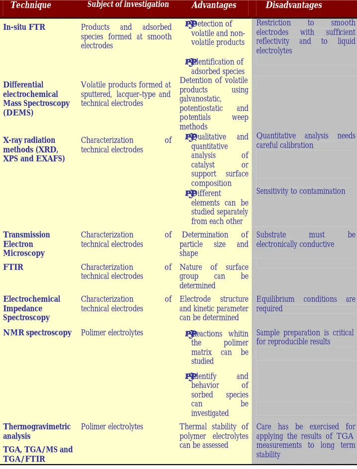
Table I - 1 Summary of techniques used for general electrochemical catalysis research and for the characterization of fuel cell components
(Reproduced from: “S. Wasmus, A. Kuver / J. of Electroanalitycal Chemstry 461 (1999) 14-31)
Technique Subject of investigation Advantages Disadvantages
In-situ FTR Products and adsorbed species formed at smooth electrodes
• Detection of
volatile and non-volatile products
• Identification of
adsorbed species
Restriction to smooth electrodes with sufficient reflectivity and to liquid electrolytes
Differential electrochemical Mass Spectroscopy (DEMS)
Volatile products formed at sputtered, lacquer-type and technical electrodes Detention of volatile products using galvanostatic, potentiostatic and potentials weep methods X-ray radiation methods (XRD, XPS and EXAFS) Characterization of technical electrodes • Qualitative and quantitative analysis of catalyst or support surface composition • Different elements can be studied separately from each other
Quantitative analysis needs careful calibration Sensitivity to contamination Transmission Electron Microscopy Characterization of
technical electrodes Determination of particle size and
shape
Substrate must be electronically conductive
FTIR Characterization of
technical electrodes Nature of surface group can be
determined
Electrochemical Impedance Spectroscopy
Characterization of
technical electrodes Electrode structure and kinetic parameter
can be determined
Equilibrium conditions are required
NMR spectroscopy Polimer electrolytes • Reactions whitin the polimer matrix can be studied • Identify and behavior of sorbed species can be investigated
Sample preparation is critical for reproducible results
Thermogravimetric analysis
TGA, TGA/MS and TGA/FTIR
Polimer electrolytes Thermal stability of
polymer electrolytes can be assessed
Care has be exercised for applying the results of TGA measurements to long term stability
I.
3
M
ORPHOLOGICALA
SPECTS OFE
LECTROCATALYSTSI.3.1ROLE OF SURFACE AREA AND METAL LOADING
As discussed above, the main requirement for an optimal alloy electrocatalyst, such as Pt-Ru, is the synthesis of highly dispersed metal particles on a carbon support. The mass activity (A/g Pt) of the catalyst for methanol electro-oxidation is strictly related to the degree of dispersion, since the reaction rate is generally proportional to its active surface area. In the case of an oxygen reduction electrocatalyst, it was found, after analysing a wide range of Pt and Pt alloy electrocatalysts, that there is an optimum particle size for the metallic phase (about 30 Å), which corresponds to a significantly high mass activity [57].
For this reaction it was found that the specific activity (mA cm-2 real surface area)
increases with the particle size, but simultaneously decreases with the active surface area. The best compromise was achieved at about 30 Å Pt particle size [57].
In the case of methanol electro-oxidation on carbon supported Pt electrocatalyst, two different trends were observed. Mc Nicol et al. [58] observed for their Pt electrocatalysts a
maximum activity at about 80 m2/g surface area. Recently, another group has shown that
the specific activity increases as a function of particle size [59]. Thus, a maximum in mass activity vs. particle size should be observed as in the case of oxygen reduction. On the other hand, Watanabe et al. [60] found that the specific activity for methanol oxidation on a carbon supported Pt electrocatalyst does not change for a particle size above 20 Å (Pt fcc structure); thus, the mass activity increases as the dispersion of the metal phase is increased [60]. These findings have been in part confirmed for the Pt-Ru system for a particle sizes above 30 Å [61]. Not much work has been carried out on electrocatalysts with particle sizes below 20 Å or catalyst formed by an amorphous phase. Generally, most of the Pt-Ru fuel cell electrocatalysts have particle sizes above 20 Å, which are crystalline with a face centred cubic (fcc) structure. Below 20 Å, the distinction between amorphous and crystalline is not so evident. For particles with 10-15 Å size about 50% of the atoms are on the surface and thus there is no ordered structure. Some recent kinetic investigations by Wieckoski et al. [62,63] on Pt surfaces covered with Ru ad-atoms have shown that the surface composed by the (111) Pt crystallographic plane covered by Ru ad-atoms performs better than any other Pt/Ru ad-ad-atoms crystallographic plane. Thus extending these considerations to high surface area Pt-Ru electrocatalysts, the specific activity should increase with the particle size. In fact, a large-size particle possess a high
surface content of (111) planes [57]. Accordingly, a maximum in the electrocatalytic activity should be observed as a function of particle size. Data shown by Ren et al. [58] may be fitted as well with a “volcano” relationship with maximum at 3 nm and shape similar to that generally observed for oxygen reduction. Unfortunately, the scattering due to a variable composition of the Pt-Ru surface, in high surface area electrocatalysts, does not allow to distinguish a clear behaviour. A second aspect concerns the loading of the metal phase on the carbon support. A high weight percent (wt%) of Pt on the carbon substrate will significantly decrease the anode thickness for the same Pt loading per
geometric electrode area (e.g., 1 mg cm-2). Using this approach, it will be possible to
enhance mass transport through the electrode and simultaneously reduce the ohmic drop. However, it has been fo und that an increase of the Pt loading (above 40 wt.%) on the carbon support decreases the dispersion of the electrocatalyst, probably due to some particle agglomeration.
I.3.2ROLE OF CARBON SUPPORT
In general preparation procedures, such as impregnation, colloidal deposition, surface reaction involve the adsorption step of active compounds on a carbon black surface. The synthesis of a highly dispersed electrocatalyst phase in conjuction with a high metal loading on carbon support has been one of the goals of the recent activity in the field of DMFCs. In this regard it is of interest to determine which carbon black is the most suitable as the support. In recent reports [64- 66], the mostly used carbon blacks were: Acetylene Black
(BET Area: 50 m2/g), Vulcan XC-72 (BET Area: 250 m2/g) and KETJEN Black (BET
Area: 1000 m2/g).
All these materials have optimal electronic conductivity but, as denoted above, they differ for the BET surface area and thus very probably in the morphology. A low surface area carbon black (such as Acetylene Black) will not allow high dispersion of the metal phase, especially for a high metal loading (low carbon content); on the other hand, it does not have micropores in the structure, which could hinder mass transport through the electrocatalytic layer. A high surface area carbon black can easily accommodate a high amount of metal phase, with a high degree of dispersion but, at the same time, the significant amount of micropores on the carbon support will not allow a homogeneous distribution of the electrocatalytic phase through the support, which could lead to mass transport limitations of the reactant as well as its limited access to the inner electrocatalytic
sites. Vulcan XC appears to be the best compromise with the presence of a small amount of micropores and a reasonable high surface area sufficient to accommodate a high loading of the metal phase. Up to now, this carbon black is the most used carbon support for the preparation of DMFCs catalysts.
I.3.3PREPARATION METHODS
There are various routes for the synthesis of the Pt-Ru/carbon black electrocatalyst; these can be grouped into two main types, i.e., an impregnation and a colloidal procedure. An impregnation procedure is characterized by an impregnation step of Pt and Ru
precursors (e.g., H2PtCl6, RuCl3, Pt(NH3)2(OH)2, Ru3CO12, Pt(NH3)2(NO)2,etc.) which is
followed by a final reduction step. This can be a chemical reduction of the electrocatalyst
slurry in aqueous solution by using N2H4, NaS2O5, NaS2O3, NaBH4
(liquid-phase-reduction) or gas-phase reduction of the impregnated carbon black by a flowing hydrogen stream. It has been shown that the impregnation method can be used for the synthesis of a multifunctional system, e.g., from a bimetallic to a quaternary electrocatalyst (Pt-Ru-Sn-W) [67]. However, it requires the use of high surface area carbon black such as Ketjen black whose limitations for the operation of a methanol fuel cell have been pointed out above. Furthermore, this procedure does not allow one to obtain high dispersions in the case of high metal loadings.
There are various colloidal deposition routes, for example, as used by Jalan [68], Bonneman et al. [69], Petrow and Allen [70], etc. The advantages of these preparation routes consist of the attainment of significantly high surface areas in the presence of high metal loading on carbon. The main disadvantages are the presence of some complex preparation steps in the overall synthesis, the use in some cases of organic compounds/solvents and the increase of costs of production. An additional method is based on the thermal decomposition. In this case, unsupported high surface area electrocatalysts are obtained by thermal decomposition of appropriate high molecular weight Pt-precursors such as Pt-carbonyl compounds [71]. Other methods, such as co-precipitation sol-gel or physical methods (e.g., sputtering [72]) have not stimulated much interest in the past, but they are now becoming interesting for the synthesis of catalysts for portable power sources [72]. The choice of the most appropriate preparation procedure relies on the following considerations. It is well known that the preparation procedure of electrocatalysts influences their physico-chemical properties and thus their activities for
methanol oxidation reaction and the oxygen reduction. The performance characteristics of an electrocatalyst depend on its chemical composition (surface and bulk), structure and morphology. Accordingly, the selected methodology of electrocatalyst synthesis should allow one to address the process for the attainment of a proper structure (crystalline or amorphous) and with a chemical composition on the surface as close as possible to the nominal or bulk composition. Since the rate of all electrocatalytic reactions is strictly related to the active surface area besides surface chemistry, the morphology of the electrocatalyst needs to be tailored. Morphology is not only related to the metal-phase area but also to the presence of micro and macro pores in the electrocatalyst support which could facilitate or hinder the mass transport properties. All these characteristics determine the cell performance even if the relative influence of each parameter is still not known in detail. It is thus necessary to select appropriate procedures for an optimization of these characteristics i.e., composition, structure, particle size, porosity etc. Generally a combination of physico-chemical and electrochemical analyses carried out on electrocatalysts with different characteristics indicates the system that better suits the scope of application in a DMFC.
I.4
C
ATHODICR
EDUCTION OFO
XYGENI.4.1GENERAL CONSIDERATIONS
Although Pt/C electrocatalysts are, at present, the most widely used materials as cathodes in low temperature fuel cells, due to their intrinsic activities and stabilities in acidic solutions, there is still great enthusiasm to develop more active, selective and less expensive electrocatalysts for oxygen reduction. Since it is widely established that Pt cannot be easily replaced (at least for the moment) by other electrocatalysts for the oxygen reduction reaction (ORR), there are a few directions that can be investigated to reduce the costs and to improve the electrocatalytic activity, especially in the presence of methanol cross-over. One is to increase Pt utilization. This can be achieved either by increasing its dispersion on carbon and the interfacial region with the electrolyte. Another successful
approach to enhance the electrocatalysis of O2 reduction is by alloying of Pt with
transition metals. This enhancement in electrocatalytic activity has been differently interpreted, and several studies were made to analyze in depth the surface properties of the proposed alloys combinations [73-77]. Although a comprehensive understanding of the numerous reported evidences has not yet been reached, the observed electrocatalytic
effects have been ascribed to several factors (interatomic spacing, preferred orientation, electronic interactions) which play, under fuel cell conditions, a favourable role in enhancing the oxygen reduction reaction (ORR) rate [78-82]. High specific activities of Pt-Cr and Pt-Cr-Co alloy electrocatalysts for oxygen reduction as compared with
that on platinum were observed in H2-air polymer electrolyte membrane fuel cells
(PEMFCs) [73,82]. The formation of a tetragonal ordered structure upon thermal treatment, in the case of Pt-Co-Cr, leads to a more active electrocatalyst than that with a Pt fcc structure [78-82]. Moreover, even in the presence of methanol cross-over, the performance of highly selective electrocatalysts for oxygen reduction would be (in theory) less affected by poisoning phenomena on account of the lower chemisorption energy of methanol on the alloys in comparison with that on Pt. Another goal in this field is to obtain very small sizes for the Pt alloy particles supported on carbon. In the case of Pt-Co-Cr particles with a tetragonal structure, the state of art electrocatalysts have a particle size of 6 nm [78-82]. In addition to the co-precipitation and impregnation methods for preparation of these alloys on a carbon support, colloidal preparation procedures have also been recently investigated [83].
I.4.2OXYGEN ELECTROREDUCTION IN DMFCS
For the development of cathode electrocatalysts for DMFCs, two main aspects should be taken into account. The electrocatalysts should be very selective for oxygen chemisorption and thus highly active for oxygen electroreduction. In other words, the electrocatalysts should have a composition which will not be poisoned by the methanol cross-over from anode to cathode while maintaining high reaction rates for oxygen reduction. In most cases, a compromise between electrocatalytic activity and resistance to poisoning is necessary. The most widely used electrocatalysts employed in low temperature fuel cells for the oxygen reduction are based on platinum. As discussed in a previous section, various studies conducted in the past, especially on carbon supported Pt electrocatalysts for oxygen reduction in phosphoric acid fuel cells, showed that the
electrocatalytic activity (mass activity, mA g-1 Pt, and specific activity, mA cm-2 Pt)
depends on the mean particle size. The mass activity for oxygen reduction reaches a maximum at a mean particle size of 30 Å, corresponding closely to the particle size at which there is a maximum in the fraction of (111) and (100) surface atoms on Pt particles of cubo-octahedral geometry [57]. On the other hand, the specific activity increases
gradually with an increase in the Pt particle size and closely follows the trend observed between the surface fraction of (111) and (100) Pt atoms and the particle size. These results have indicated that the (111) and (100) surface atoms are more electro-catalytically active than Pt atoms located on high Miller index planes [57]. Platinum atoms at edge and corner sites are considered to be less active than Pt atoms on the crystal faces. Accordingly, the mass and specific activity should decrease significantly as the relative fraction of atoms at edge and corner sites approach unity [57]. This situation occurs with Pt particles smaller than 10 Å diameter. Most of the experimental evidence observed in PEMFCs shows that crystalline electrocatalysts with about 25-30 Å particle size have higher activities than amorphous particles and also electrocatalysts with larger crystallite sizes [84].
In the case of DMFCs, an additional aspect should be considered; this is in regard to the methanol cross-over through the membrane. Methanol oxidation and oxygen reduction in the cathode compartment compete for the same sites producing a mixed potential which reduces the cell open circuit potential. In order to better understand these effects, it is worthwhile considering the mechanism for methanol oxidation and oxygen reduction; possible mechanisms are presented below.
Oxygen reduction:
O2 + Pt → Pt-O2 (28)
Pt-O2+H++ e-→ Pt-HO2 (29)
Pt-HO2+Pt →rds Pt-OH+Pt-O (30)
Pt-OH+Pt-O+3H++3e-→2Pt+2 H2O (31)
Equation (30) indicates an intermediate step requiring a dual-site reaction, and if it is the rate-determining step, it is more affected by particle size than intermediate step represented by equation (29). When the particle size becomes very small, then only the inactive edge and corner atoms will be present and dual sites of the proper orientation would not be available. Thus the activity of the particle should be lower. According to the observed variation of the reaction rate with particle size, one may conclude that the rate-determining step is represented by Eq. 12 [83].
Methanol oxidation at the cathode side
CH3OH+3Pt → Pt3-COH (32)
Pt3COH → Pt-CO+H++2Pt (33)
Pt+H2O → Pt-OH+H++ e (34)
Pt-OH+PtCO → 2Pt+CO2 (35)
In the case of methanol oxidation at the cathode, three neighboring Pt sites in a proper crystallographic arrangement will favour the methanol chemisorption. Since at high cathodic potentials the water discharging reaction (Eq. 34) is largely favored, oxidation of the methanolic residues adsorbed on the surface proceeds very fast producing a parasitic anodic current on this electrode.
When the particle size of the electrocatalyst is very small or one has an amorphous Pt electrocatalyst for the oxygen reduction, methanol chemisorption energy could be lower and hence the cathode less poisonable. But, at the same time, due to the fact that only the inactive edge and corner atoms will be present and dual sites of the proper orientation will not be available, the activity of such electrocatalyst for oxygen reduction will be lower. The best compromise is to modulate the structure and the particle size between amorphous and crystalline in order to decrease the poisoning by methanol and enhance oxygen reduction.
A second possibility is to use a promoting element for oxygen reduction which simultaneously hinders the methanol chemisorption still maintaining the proper structure and particle size.
I.4.3CARBON SUPPORTED ELECTROCATALYSTS
In order to enhance the resistance to methanol poisoning of the cathode, research activities based on the modification of Pt electrocatalyst by addition of transition metals were recently initiated in various laboratories [83, 85]. In phosphoric acid and PEMFCs the intrinsic electrocatalytic activity of Pt alloys (Pt-Cr, Pt-Ni, Pt-Cr, Pt-Cu, Pt-Fe), with a lattice parameter smaller than that of Pt, is higher than the base metal [73-82]. This effect is related to the nearest neighbour distance of Pt-Pt atoms on the surface of the fcc crystals. Since it has already been observed that the rate determining step involves the rupture of the O-O bond through a dual site mechanism, a decrease of the Pt-Pt distance
carried out in phosphoric acid fuel cells. In such cases leaching of non-noble elements produces a surface roughening with a corresponding increase of the Pt surface area. A considerably lower number of studies has been carried out on Pt-alloys as electrocatalysts for ORR in PEMFCs [73, 82, 84]. In this case, since the electrolyte anions are chemically bound to the backbone of perfluorosulfonic acid membranes and the cell temperature is relatively low, corrosion problems are minimised compared to phosphoric acid fuel cells. Also in the case of PEMFCs, there is specific evidence for an enhancement of the reaction
rate for O2 reduction on a Pt- alloy electrocatalyst [73, 82, 84]. As pointed out in a
previous sub -section, methanol chemisorption and oxygen reduction reactions require an appropriate geometrical arrangement of Pt atoms. Both processes are favoured on a Pt (111) surface, which possesses the reasonable nearest Pt-Pt interatomic distance. Thus, the poisoning effect of methanol cross-over should be more significant on the Pt (111) surface. The lack of information in this field, however, does not allow one to quantify the compensation effect due to the increased methanol oxidation rate at the sites where oxygen reduction is favoured. Beside these aspects, recent work has also taken into consideration the role played by the promoting element (Co, Cr) for the removal of strongly bonded oxygenated species on Pt through an intra-alloy electron transfer [85]. Chemisorption of oxygen molecules occur more easily on oxide-free Pt surfaces [85]. But, as well documented by cyclicvoltammetric analyses [31], methanol adsorption and oxidation are favoured on a reduced Pt surface rather than on platinum oxide. In other words, the addition of Co and Cr to Pt, simultaneously favours the oxygen reduction and methanol oxidation reactions. Furthermore, the presence of electropositive elements, alloyed to Pt, favours the chemisorption of OH species on Pt neighbouring sites. In the absence of oxygen, a small but noticeable promoting effect for methanol oxidation in a wide range of anodic overpotentials has been observed by Cr, Fe and other elements usually selected as catalytic enhancers for the oxygen reduction reaction in PEMFCs [20]. At present, it is difficult to establish if the beneficial effect on oxygen reduction is prevailing with respect to the promoting effect on methanol oxidation at DMFC cathode. In a recent paper, a limited enhancement of ORR was shown when a Pt-alloy instead of Pt was used in DMFCs [83], whereas in other cases, it was observed that Pt-alloys are less tolerant than Pt alone to methanol.
The preparation of cathodic Pt-based electrocatalysts for DMFCs are pratically the same as for the anodic electrocatalysts. However, there are some differences in terms of
the thermal treatment of a Pt-Ru or Pt-Sn alloy for methanol oxidation and that of a Pt-Cr, Pt-Co, Pt-Co-Cr electrocatalysts for oxygen reduction [73-82]. In the latter case, the activation temperature is significantly higher, around 700-900 °C, compared to 100-400°C adopted for the anodic alloy. In the case of the cathode electrocatalyst, a complete alloying is generally accompanied, in most cases, by a phase transition from fcc (cubic) to an ordered tetragonal (fct) structure. This treatment causes an increase of the mean particle size. Thus, the increase of intrinsic electrocatalytic activity is counteracted by the decrease of the surface area of the electrocatalysts.
I.5 R
EFERENCES[1] M. Neergat, D. Leveratto, U. Stimming, Fuel Cells 2, 25 (2002). [2] S. Wasmus and A. Kuver, J. Electroanal. Chemistry 1999, 461, 14.
[3] A. Blum, T. Duvdvani, M. Philosoph, N. Rudoy, E. Peled, J. Power Sources 117, 22 (2003).
[4] T. Yoshitake, H. Kimura, S. Kuroshima, S. Watanabe, Y. Shimakawa, T. Manako, S. Nakamura,, Y. Kubo, Electrochemistry 70, 966 (2002).
[5] R. Dillon, S. Srinivasan, A.S. Aricò, V. Antonucci, J. Power Sources 127, 112 (2004).
[6] X. Ren, P. Zelenay, S. Thomas, J. Davey, S. Gottesfeld, J. Power Sources 127, 112 (2004). [7] S.C. Kelley, G.A. Deluga, W.H. Smyrl, Electrochem. Solid-State Lett. 3, 407 (2000).
[8] M.K. Ravikumar, A.K. Shukla, J. Electrochem. Soc. 143 (1996) 2601. [9] J.-T. Wang, S. Wasmus, R.Savinell, J Electrochem. Soc. 143 (1996) 1233 [10] A. Kuver, I. Vogel, W. Vielstich, J. power Sources 52 (1994) 77.
[11] A. Kuver, I. Vogel, W. Vielstich, 45th Meeting of the International Society of Electrochemstry, Porto 1994, Abstract OIV -4.
[12] D.L. Maricle, B.L. Murach, L.L. Van Dine, 36th Power Sources Conference, Cherry
Hill, NJ, 1994, p. 99.
[13] A. Kuver, W. Vielstich, J. Power Sources 74 (1998) 211-218
[14] K. Sundmacher, O. Nowitzki, U. Hoffman, Chem. Ing.Tech. 69 (1997) 8197. [15] Fuel Cell Handbook
[16] B. D. McNicol, D. A. J. Rand, J. Power Sources for Electric Vehicles: studies in electrical and
Electronic Engineering, 1984, pp. 807-838.
[17] C. Lamy, J.-M. Léger, Proc. 1st International Symposium on New Materials for Fuel Cell
System, Ed. By Savadogo, P.R. Roberge and T.N. Veziroglu, Montreal, 1995, pp. 296-309.
[18] M.P. Hogarth and G.A. Hards, Platinum Metal Rev. 40 (1996) 150. [19] C. Lamy, J.-M. Léger, J.Phys. IV, C1, vol. 4 (1994) 253.
[20] B. D. McNicol, D. A. J. Rand, K. R. Williams, J. Power Sources 1999, 83, 15. [21] A. Hamnett, Catalysis Today 1997, 39, 445.
[22] M. P. Hogarth and G. A. Hards, Platinum Metal Rev. 1996, 40, 150. [23] R. Parsons, T. Van der Noot, J. Electroanal. Chem. 1988, 257, 9.
[24] D. Pletcher and V. Solis, Electrochim. Acta, 1982, 27, 775.[25] K. Wang, H. A. Gasteiger, N.M. Markovic and P. N. Ross Jr., Electrochim. Acta, 1996, 41, 2587.[26] J. B.
Goodenough, A. Hamnett, B. J. Kennedy, R. Manoharan and S. Weeks, J. Electroanal.
Chem. 1988, 240, 133.
[27] B. Beden, F. Kardigan, C. Lamy, J. M. Leger, J. Electroanal. Chem. 1981, 127, 75.
[28] K. Chandrasekaran, J. C. Wass, and J. O' M. Bockris, J. Electrochem. Soc. 1990, 137, 518.
[29] M. Watanabe and S. Motoo, J. Electroanal. Chem. 1975, 60, 275.
[30] E. Ticianelli, J. G. Berry, M. T. Paffet, and S. Gottesfeld, J. Electroanal. Chem. 81, 229, 1977.
[31] R. A. Lampitt, L. P .L. Carrette, M. P. Hogarth, A. E. Russell, J. Electroanal. Chem.
1999, 460, 80.
[32] K. Chandrasekaran, J. C. Wass, and J. O' M. Bockris, J. Electrochem. Soc. 1990, 137, 518.
[33] J. Clavilier, C. Lamy, and J. M. Leger, J. Electroanal. Chem. 1981, 125, 249.
[34] P. A. Christensen, A. Hamnett and G. L. Troughton, J. Electroanal. Chem. 1993, 362, 207.
[35] X. H. Xia, T. Iwasita, F. Ge and W. Vielstich, Electrochim. Acta 1996, 41, 711.
[36] R. A. Lampitt, L. P .L. Carrette, M. P. Hogarth, A. E. Russell, J. Electroanal. Chem.
1999, 460, 80.
[37] W. Vielstich, P. A. Christensen, S. A. Weeks and A. Hamnett, J. Electroanal. Chem.
1988, 242, 327.
[38] B. Beden, F. Hahn, S. Juanto, C. Lamy and J.-M. Legér, J. Electroanal. Chem. 225, 1987, 215.
[39] B. Beden, C. Lamy, A. Bewick and K. Kunimatsu, J. Electroanal. Chem. 121, 1981, 343. [40] S. Juanto, B. Beden, F. Hahn, J.-M. Legér and C. Lamy, J. Electroanal. Chem. 237, 1987, 119; ibid. 238 (1987) 323.
[41] M. M. P. Janssen, J. Moolhuysen, Electrochim. Acta 1976, 21, 861.
[42] A. B. Anderson, E. Grantscharova and S. Seong, J. Electrochem. Soc. 1996, 143 , 2075. [43] J. Mc Breen and S. Mukerjee, J. Electrochem. Soc. 1995, 142, 3399.
[44] L. Troger, A. Freund, P. Albers, K. Seibold, G. Prescher, Ber. Bunsenges, Phys. Chem. 101, 1997, 851.
[45] P.G. Allen, S.D. Conradson, M.S. Wilson, S. Gottesfeld, I.D. Raistrick, J. Valerio, M. Lovato, Electrochem. Acta, 39, 1994, 2415.
[46] T. Torre, A.S. Aricò, V. Alderucci, V. Antonucci, N. Giordano, Appl. Catal. 114, 1994, 257.
[47] A.S. Aricò, P. Cretì, N. Giordano, V. Antonucci, P.L. Antonucci, A. Chuvilin, J. Appl.
Electrochem.. 26, 1996, 959.
[48] A.S. Aricò, P. Cretì, H. Kim, R. Mantenga, N. Giordano, V. Antonucci, J. Electrochem.
Soc., 143, 1996, 3838.
[49] M Uchida, Y. Aoyama, N. Tanabe, N. Yanagihara, E. Eda, A. Ohta, J. Electrochem.
Soc., 142, 1995, 2572.
[50] S.C. Roy, P.A. Christensen, A Hamnet, K.M. Thomas, V. Trapp, J. Electrochem.
Soc.,143, 1996, 3073.
[51] I. Yamanaka, K. Otsuka, Electrochim. Acta 34, 1989, 211. [52] H. Nakajima, H. Kita, Electrochim. Acta 33, 1988, 521. [53] R. Liu, P.S. Fedkiw, J. Electrochem. Soc., 139, 1992, 3514.
[54] S. Wasmus, R.F. Savinell, H. Moaddel, M.H. Litt, C. Rogers, A. Valeriu, G.D.
Mateescu, D.A. Tryk, W.A. Daunch, P.L. Rinaldi, 187th Meeting of the Electrochemical
Society, Reno/Nevada, May 21-26 1995.
[55] R.S. Samms, S. Wasmus, R.F. Savinell, J. Electrochem. Soc., 143, 1996, 1225. [56] B. Gupta, J.G. Highfield, G.G. Scherer, J. Appl. Polym. Sci. 51, 1994, 1659.
[57] N. Giordano, E. Passalacqua, L. Pino, A. S. Aricò, V. Antonucci, M. Vivaldi and K. Kinoshita, Electrochimica Acta 1991, 36, 1979.
[58] B. D. McNicol, D. A. J. Rand, K. R. Williams, J. Power Sources 1999, 83, 15. [59] J. A. Poirier, The Electrochemical Society Interface, Winter 1994, p. 49.
[60] M. Watanabe S. Saegusa, and P. Stonehart, J. Electroanal. Chem. 1989, 271, 213.
[61] X. Ren, P. Zelenay, S. Thomas, J. Davey, and S. Gottesfeld, J. Power Sources 2000, 86, 111.
[62] W. Chrzanowski and A. Wieckowski, Langmuir, 1998, 14, 1967.
[63] H. Kim and A. Wieckowski, Third International Symp. On New Materials for Fuel Cells.
[64] P. S. Kaurenan and E. Skou, J. Electroanal. Chem. 1996, 408, 189. [65] M. K. Ravikumar and A. K. Shukla, J. Electrochem. Soc. 1996, 143, 2601.
[66] J. B. Goodenough, A. Hamnett, B. J. Kennedy, S. A. Weeks, Electrochim. Acta 1987, 32 1233.
[67] A. S. Aricò, Z. Poltarzewski, H. Kim, A. Morana, N. Giordano and V. Antonucci. J.
Power Sources 1995, 55, 159.
[68] V. Jalan, Extended Abstracts, Electrochemical Society, Los Angeles, CA, Fall Meeting, Abstract 192 (October 1979).
[69] H. Bonnemann, R. Brinkmann, W. Brijoux, E. Dinjus, T. Joussen, B. Korall, Angew.
Chem. 1991, 103, 1344.
[70] H. G. Petrow and R. J. Allen, U.S. Pat. 3, 992, 331, 1976.
[71] K. Machida, A. Fukuoka, M. Ichikawa and M. Enyo, J. Electrochem. Soc., 1991, 138, 1958.
[72] C. K. Witham, W. Chun, T. I. Valdez and S. R. Narayanan, Electrochem. Solid-State Lett.
2000, 3, 497.
[73] S. Mukerjee, S. Srinivasan, J. Electroanal. Chem. 1993, 357, 201.
[74] T. R. Ralph, G. A. Hards, S. D. Flint, J. M. Gascoyane, Fuel Cell Seminar Abstracts, p. 536, Palm Springs, CA, Nov. 16-19, 1998.
[75] M. T. Paffet, G. J. Beery, S. Gottesfeld, J. Electrochem. Soc. 1998, 135, 1431.
[76] M. Watanabe, K. Tsurumi, T. Mizukami, T. Nakamura, P. Stonehart, J. Electrochem. Soc.
1994, 141, 2659.
[77] A. Freund, J. Lang, T. Lehman, K. A. Starz, Cat. Today 1996, 27, 279. [78] V. Jalan, E. J. Taylor, J. Electrochem. Soc. 1983, 130, 2299.
[79] S. Gottesfeld, M. T. Paffett, A. Redondo, J. Electroanal. Chem. 1986, 205, 163. [80] B. C. Beard, P. N. Ross, J. Electrochem. Soc. 1970, 137, 3368.
[81] K. T. Kim, J. T. Whang, Y. G. Kim, J. S. Chung, J. Electrochem. Soc. 1993, 140, 31. [82] S. Mukerjee, S. Srinivasan, M. P. Soriaga, J. McBreen, J. Electrochem. Soc. 1995, 142, 1409.
[83] M. Neergat, A. K. Shukla, K. S. Gandhi, J. Appl. Electrochem. 2001, 31, In press.
[84]Y. Takasu, T. Iwazaki, W. Sugimoto and Y. Murakami, Electrochemistry Communications
2000, 2, 671.
[85] A. S. Aricò, A. K. Shukla, H. Kim, S. Park, M. Min and V. Antonucci, Appl. Surf.
Sci.
CHAPTER II
I
NFLUENCE OFC
ATALYSTU
TILIZATION ON THEE
LECTROCHEMICALB
EHAVIOUR OFL
OWT
EMPERATUREDMFC
II. I
NTRODUCTIONThe increasing demand for quality, energy density, and time-performance of power supply is the principal driving force in the portable power production market. For this application technology, it is necessary to work using catalysts having a high activity at room temperature. In order to reach this goal, the first step of this study was focused on an analysis of the influence of the different Pt loading on the electrochemical behaviour of a DMFC, to get information on catalyst utilization for this application.
II.
1
E
XPERIMENTALIn order to reduce ohmic drop, mass transport and manufacturing problems deriving by the use of thick electrodes, the present DMFC catalysts for low temperature applications are usually unsupported Pt and Pt-Ru alloys [1-3]. Yet, the presence of catalyst agglomeration effects in unsupported catalysts significantly limits their utilisation in polymer electrolyte fuel cell systems. In this work, an 85% Pt-Ru (1:1 a/o) alloy supported on Vulcan XC-72 and a 60% Pt/Vulcan XC-72 were in-house prepared and utilized in DMFCs for the electro-oxidation of methanol and the electrochemical reduction of oxygen, respectively. Both catalysts were in-house prepared by using a sulphite complex route [4]. The preparation procedure involved three main steps: (i) synthesis of the Pt and
Ru sulphite precursors, (ii) decomposition of the precursors by H2O2 into colloidal
amorphous oxides, (iii) gas phase reduction in a hydrogen stream to form metallic phases. A description of the preparation procedure has been reported elsewhere [5]. These carbon supported catalysts associate high metal surface area to a suitable concentration of the active phase that allows to maintain a low electrode thickness.
X-ray diffraction powder (XRD) patterns of the anode and cathode catalysts were
obtained on a Philips X’Pert X-ray diffractometer using a CuKα-source. TEM analysis
Nafion ionomer (85 wt% catalyst, 15 wt% Nafion ionomer on a dry basis) by ultrasonic
treatment. Pt loadings ranging between 1 and 10 mg cm-2 were used for both anode and
cathode. A Nafion 117 membrane was used as electrolyte. Membrane -electrode assemblies (MEAs) were formed by a hot-pressing procedure [3] and subsequently installed in a fuel
cell test fixture of 5 cm2 active area. This latter was connected to a test station including an
HP6060B electronic load or to an EG&G electrochemical apparatus consisting of a PAR 273A Potentiostat/Galvanostat and a 20A Current Booster.
For single cell polarization experiments, aqueous methanol (1M) was pre-heated at the same temperature of the cell and fed to the anode chamber of the DMFC through a peristaltic pump; dry air, pre-heated at the same temperature of the cell, was fed to the cathode. Atmospheric pressure in the anode and cathode compartments was used in most
experiments; whereas, 2 atm rel. was settled at the cathode side in a few experiments to
observe the effects of cathode pressure in counteracting methanol cross-over. Reactant
flow rates were 2 ml min-1 and 350 ml min-1 for methanol/water mixture and air stream,
respectively. Single cell performances were investigated by steady-state galvanostatic polarization measurement.
II.
2
R
ESULTS ANDD
ISCUSSIONII.2.1PHYSICO-CHEMICAL CHARACTERIZATION
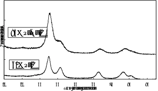
X-ray diffraction analysis (Fig. II-1) shows the diffraction peaks of the fcc structure typical of Pt and Pt-Ru alloy. Due to the high concentration of noble metals supported on
carbon black, only a slight X-ray scattering for graphitic carbon is observed at about 2θ ≅
25°. A shift to higher Bragg angles and an increase of peak broadening is observed for the Pt-Ru catalyst with respect to pure Pt, indicating a decrease of lattice parameters and average particle size, respectively. The lattice parameter is about 21 Å for the Pt-Ru alloy catalyst and 37 Å for the Pt catalyst, as calculated by the Sherrer equation.
Fig II-1. XRD patterns of 85% Pt-Ru/C and 60% Pt/C catalysts.
TEM observation of the two catalysts (Fig. II-2) shows a good dispersion of the metal particles on the support, even if some particle agglomerations due to the high concentration of metal on carbon support are observed.
15 25 35 45 55 65 75 85 95
Two theta degrees
Counts /a.u.
85%Pt-Ru/C
60%Pt/C
15 25 35 45 55 65 75 85 95
Two theta degrees
Counts /a.u.
85%Pt-Ru/C
60%Pt/C
Fig II-2. Transmission electron micrographs of (a) 85% Pt-Ru/C and
(b) 60% Pt/C catalysts.
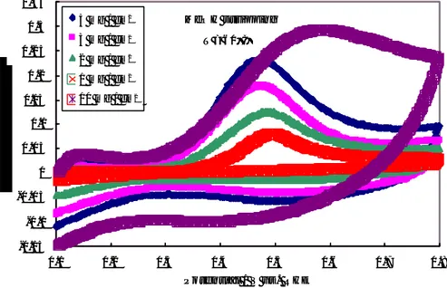
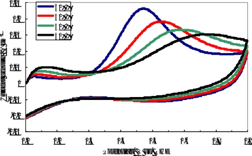
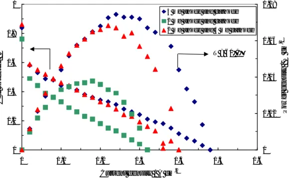
II.2.2ELECTROCHEMICAL CHARACTERIZATION
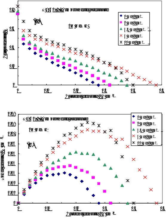
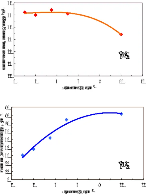
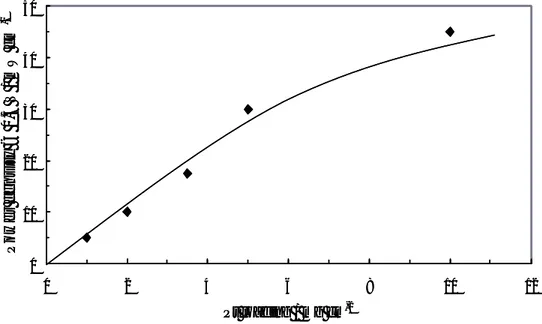
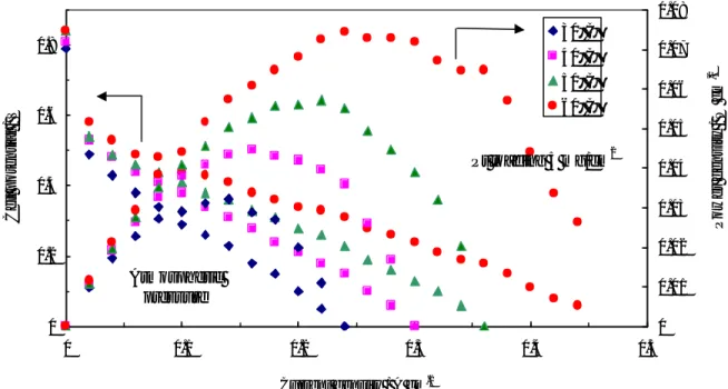
The influence of noble metal loading on the performance of the DMFC operating at low temperatures (30-60°C) was first investigated by steady-state polarization measurements, feeding 1 M MeOH solution to the anode and dry air to the cathode side under atmospheric conditions. Various test were carried out in order to optimize the Pt loading in each electrode for low temperature operation. Pt loadings ranging between 1
and 10 mg cm-2 were used for both anode and cathode. Figure II-3 shows the polarisation
and power density curves obtained at 30°C for the different cells equipped with the various Pt loadings. In these experiments the same Pt loading was present at the anode and cathode. At 30°C the enhancement of power density, increasing the Pt loading from
3.5 to 5 mg·cm-2, is quite significant. Less significant is the improvement increasing the Pt
loading from 5 to 10 mg·cm-2. Accordingly, 5 mg·cm-2 would be a suitable Pt loading for
this application. This is confirmed by successive experiments at different temperatures.