Ph.D. degree in Information and Communication Technologies XXXI Cycle
Ph.D. Thesis
Design and Implementation of Machine
Learning Techniques for Modeling and
Managing Battery Energy Storage Systems
Candidate Massimiliano LUZI ID number 1146457 Thesis Advisor Antonello RIZZI Co-Advisor Fabio Massimo FRATTALE MASCIOLI
Prof. Antonio D’ALESSANDRO(chairman) Prof. Francesco RIGANTIFULGINEI
Prof. Alessandro BUSACCA Dott. Alessandra BUDILLON
This thesis has been reviewed by: Prof. Giorgio RIZZONI
Prof. Federico BARONTI
Design and Implementation of Machine Learning Techniques for Modeling and Manag-ing Battery Energy Storage Systems
Ph.D. thesis. University of Rome “La Sapienza” © 2019 Massimiliano LUZI. All rights reserved
UNIVERSITY OF ROME “LA SAPIENZA”
Abstract
Faculty of Information Engineering, Informatics, and Statistics Department of Information Engineering, Electronics, and
Telecommunications Doctor of Philosophy
Design and Implementation of Machine Learning Techniques for Modeling and Managing Battery Energy Storage Systems
by Massimiliano LUZI
The fast technological evolution and industrialization that have interested the humankind since the fifties has caused a progressive and exponential increase of CO2 emissions and Earth temperature. Therefore, the research community and the political authorities have recognized the need of a deep technological revolution in both the transportation and the energy distribu-tion systems to hinder climate changes. Thus, pure and hybrid electric pow-ertrains, smart grids, and microgrids are key technologies for achieving the expected goals. Nevertheless, the development of the above mentioned tech-nologies require very effective and performing Battery Energy Storage Sys-tems (BESSs), and even more effective Battery Management SysSys-tems (BMSs). Considering the above background, this Ph.D. thesis has focused on the development of an innovative and advanced BMS that involves the use of machine learning techniques for improving the BESS effectiveness and effi-ciency. Great attention has been paid to the State of Charge (SoC) estimation problem, aiming at investigating solutions for achieving more accurate and reliable estimations. To this aim, the main contribution has concerned the development of accurate and flexible models of electrochemical cells.
Three main modeling requirements have been pursued for ensuring ac-curate SoC estimations: insight on the cell physics, nonlinear approximation capability, and flexible system identification procedures. Thus, the research activity has aimed at fulfilling these requirements by developing and inves-tigating three different modeling approaches, namely black, white, and gray box techniques. Extreme Learning Machines, Radial Basis Function Neural Networks, and Wavelet Neural Networks were considered among the black
box models, but none of them were able to achieve satisfactory SoC estima-tion performances. The white box Equivalent Circuit Models (ECMs) have achieved better results, proving the benefit that the insight on the cell physics provides to the SoC estimation task. Nevertheless, it has appeared clear that the linearity of ECMs has reduced their effectiveness in the SoC task. Thus, the gray box Neural Networks Ensemble (NNE) and the white box Equiva-lent Neural Networks Circuit (ENNC) models have been developed aiming at exploiting the neural networks theory in order to achieve accurate mod-els, ensuring at the same time very flexible system identification procedures together with nonlinear approximation capabilities.
The performances of NNE and ENNC have been compelling. In par-ticular, the white box ENNC has reached the most effective performances, achieving accurate SoC estimations, together with a simple architecture and a flexible system identification procedure.
The outcome of this thesis makes it possible the development of an inter-esting scenario in which a suitable cloud framework provides remote assis-tance to several BMSs in order to adapt the managing algorithms to the aging of BESSs, even considering different and distinct applications.
Acknowledgements
I would like to express my special thanks of gratitude to Prof. Antonello Rizzi for the fundamental support provided during the past years, starting from the period of the Master’s Thesis, until the last days of my Ph.D. . I will never forget his help and his suggestions. My life would be very different without our late-afternoon talks.
I would like to thank also my co-advisor Prof. Fabio Massimo Frattale Mascioli, Luigi Anniballi, and all the people from the POMOS laboratories for their valuable and undiscussed support and the opportunities otherwise I would not be able to enjoy. Special thanks go to Maurizio Paschero, not only for his help during my Ph.D. years, but also for having trusted me as a photographer for his daughter’s baptism.
My most sincere gratitude is for Prof. Giorgio Rizzoni for the opportunity he gave me to work at the Center for Automotive Research, for his help, and for our guitar talking and the numerous jam sessions.
A very special thanks go to the “CAR-riola”, Fabrizio Donatantonio, Nicola Zanardi, Matteo Galli, and Stefano Leonori, the most crazy Italian gang walk-ing in the street of Ohio. All of you made the life in Columbus easier and happier. In particular, I would like to acknowledge Nicola, for the sincere friendship we have built.
I am also grateful with all my lab-mates, Stefano Leonori, Alessio Mar-tino, Enrico Maiorino, Antonello Rosato, Rosa Altilio, Enrico de Santis, and Antonino Capillo. We spent great time together. In particular, a special men-tion is for Stefano, who shared with me all the good and bad moments of our Ph.D., supporting each other.
Last but not least, I would like to express my gratitude to all my fam-ily, in particular to my parents Agnese Mura and Patrizio Luzi, to my sister Annalisa Luzi and her husband David Camilli, and in particular to my dar-ling nephew Alessandro. Further thanks are for my other family, Riccardo Deiana, Angelo Deiana, and Gabriele Marozzi for the not necessary words. My acknowledgement is also for my band, Davide Ubaldi, Dino Manoni, Daniele Sangiorgi, and Sandro Elia, and for all the numerous members of “La Banda”.
Finally, my most important thanks are for Valentina Taschini, to whom this thesis is dedicated, simply for being her and nothing more. The past three years have been difficult for us, being far away to each other, but her sure presence, support, and help never made me feel the distance from her.
Contents
Abstract i
Acknowledgements iii
1 Introduction 1
1.1 Background . . . 1
1.2 Objective of the Research . . . 17
1.3 Overview on the Research Topic . . . 19
1.3.1 Battery Management System . . . 19
Monitoring . . . 19
State of Charge . . . 20
State of Health . . . 23
Balancing . . . 27
1.3.2 Modeling Techniques . . . 28
2 Machine Learning Techniques 31 2.1 Neural Networks . . . 31
2.2 Evolutionary Algorithms . . . 39
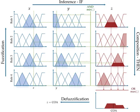
2.3 Fuzzy Logic . . . 44
2.4 Multi-Swarm Hybrid Genetic Particle Swarm Optimization. . 49
3 BMS Algorithms 52 3.1 Comparison Between EKF and SR-UKF for SoC Estimation . . 52
3.1.1 Nonlinear Kalman Filters . . . 52
3.1.2 Hardware in The Loop Comparison . . . 56
Experimental Setup. . . 56
Experimental Results . . . 59
3.2 Real Time Optimal Balancing with a Binary PSO . . . 61
3.2.1 Passive Balancing Architecture . . . 61
3.2.2 Proposed Balancing Algorithm . . . 62
3.2.3 Tests and Results . . . 66
Experimental Results . . . 67
4 Modeling Electrochemical Cells 74 4.1 Modeling Background . . . 74
4.2 White Box Technique . . . 76
4.2.1 Nonlinear Equivalent Circuit Model . . . 76
Model Background . . . 76
Nonlinear RC Dipole for Modeling the Low-Pass Tran-sient Response . . . 78
System Identification Procedure for the Nonlinear RC Dipole . . . 80
Performance Analysis . . . 83
4.2.2 Linear Equivalent Circuit Model . . . 88
Flexible Identification Procedure . . . 88
Performance Analysis . . . 90
4.2.3 Mechanical Inspired Equivalent Circuit Model . . . 93
Mechanical Analogy . . . 93
System Identification . . . 97
Performance Analysis . . . 99
4.3 Black Box Technique . . . 104
4.4 Gray Box Technique . . . 105
4.4.1 Neural Networks Ensemble Model . . . 105
Instantaneous Timescale Modeling . . . 108
Dynamic Timescale Modeling . . . 110
Quasi-Stationary Timescale Modeling . . . 111
4.4.2 Model Training and Testing . . . 112
Data Sets . . . 112
Training Procedure . . . 114
4.4.3 Model Performances . . . 118
System Identification Task . . . 118
SoC Estimation Task . . . 121
4.5 A Neural White Box Model: Equivalent Neural Network Circuit124 4.5.1 Equivalent Neural Network Circuit . . . 124
Model Architecture . . . 124
Neural Network Implementation . . . 127
4.5.2 Experimental Setup. . . 128
Data Sets . . . 128
ENNC Configurations . . . 131
4.5.3 Performances Analysis. . . 133
Performance Metrics . . . 133
Discussion on the ENNC Configurations . . . 136
4.6 Comparison Among White Box, Black Box, and Gray Box Mod-els . . . 139
5 Hardware Implementations 145 5.1 BMS Prototype. . . 145
5.2 Battery cycler . . . 147
5.3 Hardware in The Loop Equipment . . . 149
6 Conclusions 152
List of Publications 159
Chapter 1
Introduction
1.1 Background
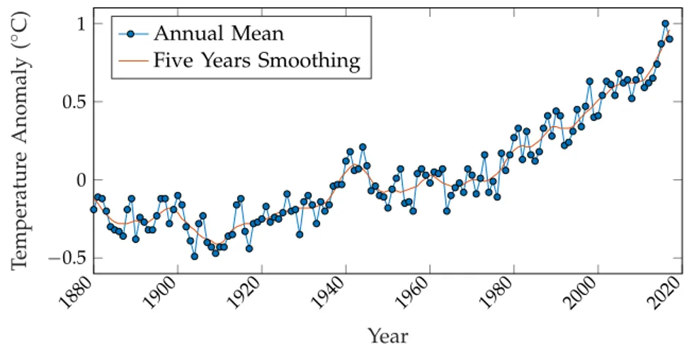
Climate changes and global warming are some of the most relevant issues of modern era. Indeed, the wide technological evolution that has interested the nineteenth century has caused a progressive and exponential increase of the Earth temperature, as shown in Figure1.1.
1880 1900 1920 1940 1960 1980 2000 2020 −0.5 0 0.5 1 Year Temperatur e Anomaly ( ◦C) Annual Mean
Five Years Smoothing
Figure 1.1: Variation of the land-ocean temperature with base period 1951-1980. Data downloaded fromdata.giss.nasa.gov/gistemp/graphs.
One of the main reasons of this increasing trend is related to the uncon-trolled emissions of carbon dioxide (CO2). In general, a suitable concentra-tion of CO2and of the other natural gases composing the Earth atmosphere creates a beneficial greenhouse effect that has allowed and still allows a fa-vorable environment for living beings. Nevertheless, any alteration on the concentration of the greenhouse gases results in a significant and long last-ing variation of the climatic conditions. Unfortunately, since the Industrial Revolution until now the human activity has caused a progressive and un-restrained increase of the CO2concentration. In particular, this phenomenon
has become progressively more relevant together with the wide industrial-ization and the very fast technological evolution that have interested the hu-mankind since the fifties.
Several consequences are related to global warming and to the resulting climate changes. First of all, variations in the biological environment cause the extinction of several animal and plant species. Second, melting of ice is an immediate effect of global warming. Specifically, this results in retreat of glaciers, decline of Arctic sea ice, and rise of the sea levels. Third, global warming affects also the seasonal cycles, with consequent changes in several ecosystems, alterations in the plant and animal life cycles, anomalies in the rainfall rhythms, and extreme weather conditions. Other consequences are the acidification of oceans, expansion of deserts, and droughts. Moreover, all of these phenomena will affect also the human society, with alterations in the crop production and in general in the public health.
The above discussed negative situation has led both the research com-munity and the political authorities at focusing on the mitigation of global warming. Therefore, 195 countries have attended to the United Nation Cli-mate Change Conferenceheld in Paris on December 2015 aiming at discussing about how to hinder climate changes. During this conference, it has been ne-gotiated the Paris Agreement [1] in which the signatory countries has pledged to adopt solutions aiming at «holding the increase in the global average tem-perature to well below 2◦C above pre-industrial levels and pursuing efforts to limit the temperature increase to 1.5 ◦C above pindustrial levels, re-cognizing that this would significantly reduce the risks and impacts of cli-mate change»1. The agreement states that each country shall determine au-tonomously the best contribution for achieving the expected goals. More-over, each of them has to make its economical system consistent with a low greenhouse gas emissions and climate-resilient environment. Indeed, each country shall make efforts «to reach global peaking of greenhouse gas emis-sions as soon as possible, [...] and to undertake rapid reductions thereafter in accordance with best available science, so as to achieve a balance between anthropogenic emissions by sources and removals by sinks of greenhouse gases in the second half of this century [...] »2.
A graphical analysis of the expected goals and a forecast of the green-house gas emissions trend by 2030 is shown in Figure1.2. The negative ef-fect of the human activity held until now is evident. Indeed, from one side
1Article 2.1.a from the Paris Agreement. 2Article 4.1 from the Paris Agreement.
the historical data shows a constant increasing trend in the greenhouse gas emissions. On the other hand, the figure highlights that the policies and the pledges adopted so far are not satisfactory for fulfilling the expected goals.
Figure 1.2: Analysis of the CO2 emissions and comparison with the
Paris Agreement’s goals by December, 2018. Figure downloaded at www.
climateactiontracker.org.
The main reason of the inadequacy of the adopted solutions is attributable to the ambitious and challenging technological revolution that is necessary for matching the goals of the Paris Agreement. From the industrial point of view, radical changes in the manufacturing process must be introduced in order to limit the emissions of the industrial plants. Consequently, many companies must provide huge investments for pursuing the aim of the agree-ment. The most immediate solution consists in the renovation of the indus-trial equipment. Nevertheless, often the simple modernization of the plants could not be sufficient for matching the very demanding requirements con-cerning the greenhouse gas emissions. Therefore, the most compelling so-lution consists in a deep redesign of the entire manufacturing processes in order to develop plants natively green. It is clear that this process is very de-manding for many companies, and it requires structural changes and suitable settling times.
Besides the industrial area, the transportation and the Energy Distribu-tion System (EDS) are widely recognized as the two main fields where to act for hindering global warming.
The transportation system has been historically based on fossil fuel propulsion. The main advantage of this solution has been always recognized in the very high energy density of fuel that ensures very fast refills and long distance ranges. Thus, gasoline-powered vehicles have dominated the trans-portation technology so far even if electric cars have got a reliable produc-tion with Thomas Parker in 1884 [2] about 20 years before of the Ford Model T. Nevertheless, traditional Internal Combustion Engines (ICEs) are effective but inefficient machines [3]. Indeed, the average efficiency is around 20 %, meaning that most of the fuel energy is dissipated in heat and in the produc-tion of waste gases, in particular CO2. Therefore, considering also that the total number of vehicles in use worldwide has increased from 126 millions of the sixties to 1.3 billions in 2014, it is straightforward to think about conven-tional cars as one of the most relevant causes of the increasing trend in the CO2concentration.
Several actions have been done aiming at reducing the greenhouse gas emissions of conventional vehicles, such as the introduction of international rules like the European Emission Standards. The adoption of these rules have forced car makers at finding solutions for developing more efficient ICEs and for introducing novel strategies to limit the related emissions. Nevertheless, these solutions alone are far to be sufficient for achieving the goals of the Paris Agreement. Moreover, the conventional transportation technology is going to be completely unsustainable considering that the number of cars is going to further increase in the next future. Therefore, many countries and car makers have recognized the need of coming back to the electric propulsion, and to convert the transportation technology to Electric Vehicles (EVs) and Hybrid Electric Vehicles (HEVs) [4], [5].
A simplified block diagram of the EV and HEV architectures is shown in Figure1.3. The powertrain of an EV is in general very simple. It consists of a battery pack, a power converter, and an electric motor. The power converter is in charge of performing two tasks. The first one consists in converting the DC voltage of the battery pack to the suitable voltage specifications of the electric motor. Very often, the power converter is actually an inverter performing a DC-AC conversion because of the common use of AC induction motors for the wheels traction. The second task is to control the amount of power to be provided to the electric motor accordingly with the power required from the driver.
HEVs have a more complicated architecture because electric and conven-tional propulsion coexist in the same powertrain. HEVs can be split in two
Battery
Pack ConverterPower Motor Transmission
(a) Fuel Tank ICE Power Converter Battery
Pack ConverterPower Motor
Transmission
(b)
Fuel
Tank ICE Clutch Battery
Pack ConverterPower Motor
Transmission
(c)
Figure 1.3:Powertrain architecture of electrified vehicles. (a) EVs. (b) Series-HEVs. (c) Parallel-Series-HEVs.
main categories: series-hybrid and parallel-hybrid. In the series architecture only the electric motor provides traction to the driving wheels, whereas the ICE works as a range extender being connected to a generator in order to recharge the battery pack. Two power converters are required: the first one is connected between the battery pack and the electric motor having the same role seen for EVs. The second power converter is connected between the gen-erator and the battery pack in order to allow the recharging process. Likewise EVs, the required power must be satisfied only by the electric propulsion. In the parallel-hybrid architecture both the ICE and the electric motor can drive the wheels. Therefore, the power required by the user must be satisfied by
means of an intelligent control of the powertrain. Indeed, it is possible to rec-ognize at least four different operating modes. The first one is the full electric propulsion, in which only the electric motor is used for driving the wheels. Similarly, only the conventional propulsion is used in the ICE mode. The third is the hybrid mode, in which the required power is satisfied by using the ICE and the electric motor together. Finally, in the regenerative break-ing mode the inertia of the car is used to recover energy for rechargbreak-ing the batteries. Moreover, in some architecture it is possible to introduce a further generator that is connected to the ICE in order to create a more complicated series-parallel architecture. In this case, it is possible to have a further mode in which the wheels are driven only by the electric motor, while the ICE is used for recharging the batteries through the related generator.
Besides the zero and the low emissions properties, respectively, EVs and HEVs have the further advantage of a more efficient powertrain with respect to the conventional ones. Indeed, electric motors can achieve efficiency up to more than 90 % on the whole rotational speed range. Moreover, very often electric motors do not need a multi-gear transmission system because they can handle higher rotational speeds with respect to ICEs. Consequently, it is possible to avoid complex transmission gearboxes, further improving the efficiency of the powertrain. Nevertheless, the main drawback of EVs is their limited autonomy and limited flexibility of the refill process resulting in the range anxiety commonly perceived by the drivers. HEVs provide a suitable palliative to these drawbacks thanks to the installation of the ICE in their powertrain, and for this reason their commercialization is being more promi-nent with respect to EVs. Nevertheless, the actual reduction of CO2emissions lays widely in a consistent diffusion of EVs, and therefore it is necessary to furtherly improve their performances, as well as to create the most suitable environment for their diffusion, starting from a wide revolution of the EDS.
EDS has been based so far on the concept of centralized power genera-tion and decentralized loads. In this context, the most diffused power plants have relied on fossil fuels, where electric energy is harvested by burning coal, natural gas, or petroleum [6], [7]. It is straightforward that also the above described EDS has contributed in the increasing trend of CO2 emis-sions and global warming. Moreover, the traditional grid is also character-ized by a very rigid and inefficient operating condition. First, its stability is deeply dependent on the synchronous AC electric machines of the cen-tralized power plants. As a direct consequence, the traditional grid tech-nology itself makes harder the transition to alternative and greener power
sources [8]. Second, the centralized architecture implies that the distribution must be organized and operated following a tree architecture in which of-ten the plants are far away from the actual loads. Thus, the energy has to flow among very long power lines, power transformers, transmission lines, transmission substations, distribution lines, distribution substations, and fi-nally to the loads. This means that the entire architecture has an intrinsic lack of efficiency because of the losses unavoidably present in each node of the tree. Moreover, this strict operating architecture has two further implicit drawbacks. First, customers do not have any consciousness of the grid, of the generation processes, of the energy prices, and consequently they have a very limited opportunity of participating to the energy market. Second, it is very hard to control the grid, and it is almost impossible to think about a dynamic reconfiguration of the distribution architecture. This results in a further lack of efficiency and in an implicit weakness of the grid, because pos-sible failures can easily lead to blackouts [9], [10]. For the above discussed reasons the traditional EDS looks widely inadequate for facing the more and more increasing energy demand due to the deep pervasiveness of technology and the incoming diffusion of EVs that will characterize the modern society. Moreover, it is likewise inadequate for reducing CO2emissions. Therefore, a deep re-design of the entire EDS is necessary. In particular, the smart grid [7], [11]–[14] and the microgrid [8], [15], [16] concepts have been recognized as the most promising technologies for implementing the next generation EDS. Smart grid and microgrid aim at creating a suitable environment for con-verting the rigid, weak and inefficient distribution system based on central-ized fossil fuel power plants to a flexible and reliable grid based on decen-tralized Renewable Energy Sources (RESs) [17]–[19]. From the smart grid perspective, the distribution system must be revolutionized through a deep introduction of Information Technology (IT) tools [7]. The aim is to create a constant two-way communication between suppliers and customers, as well as to equip each node with suitable smart meters aiming at monitoring in real-time the operative condition of the grid. The introduction of IT tools allows to increase the flexibility of the distribution system, and to prepare the grid for an effective use of RESs. Indeed, the constant monitoring of the system pro-vides a real-time full knowledge of both the generation and the load status. If this information were unnecessary for the traditional grid since both genera-tion and loads were considered substantially constant along the network, the installation of RESs, Energy Storage Systems (ESSs), DC fast charge station for EVs, as well as the changed habits of customers make generation and load
profiles very variable both temporally and spatially. Therefore, a constant monitoring of the entire grid is mandatory for achieving a more effective operation of the system. Moreover, a deep use of sensors makes EDS more reliable and efficient. Indeed, it permits a prediction and a prompt detec-tion of incoming failures, as well as the actuadetec-tion of remote fixing, whenever applicable. Furthermore, the decentralized architecture allows an adaptive reconfiguration of the grid on the basis of the actual generation-load status, aiming at increasing the efficiency of the entire system.
The constant communication between suppliers and customers is the other foundation concept of smart grid. This communication aims at mak-ing customers more active and more conscious of the energy market, bemak-ing informed in real-time about the energy prices and the grid status. Thus, customers can have an active participation in the distribution system, also because they are encouraged at being local suppliers by means of personal RESs, as well as personal ESSs, Plug-in EVs (PEVs), or Plug-in HEVs (PHEVs) [20]–[22].
The above described foundation concepts imply that next generation smart grids shall be composed of Zero-net Energy Nodes (ZENs) [8], namely part of the grid able to reach a self-sufficient energy balance by taking advan-tage of local RESs and local ESSs. Microgrids are the most feasible candidates for implementing a ZEN node. A microgrid is an atomic EDS that behaves like a single entity with respect to the main grid [23]. It is composed of in-terconnected loads, local generation plants, mainly RESs, and ESSs. Thanks to the local generation and the presence of ESSs, a microgrid can be com-pletely self-sufficient with respect to the grid, and therefore it can work in an islanded mode. Nevertheless, the most challenging scenario sees the mi-crogrid still connected to the main grid, such that the customer can acts as a “prosumer”, i.e. both an energy producer and consumer at the same time. Therefore, microgrids play a key role in the implementation of the smart grid concept, involving each customer at having an active role in the energy mar-ket. Indeed, each microgrid must be equipped with effective Energy Manage-ment Systems (EMSs) for achieving a more efficient, more effective, smarter, and more remunerative use of the available energy [24], [25].
It is clear from the above discussion the importance that EVs, HEVs, smart grids, and microgrids have for leading the radical technological and social revolution required by the Paris Agreement. Although these technologies be-long to different application fields, all of them share ESSs as an invariant de-vice for achieving significant improvements with respect to the conventional
technologies.
Concerning EVs and HEVs, the importance of ESSs is straightforward. The availability of effective and reliable battery packs is the first step for im-proving the vehicle performances, as well as for ensuring the actual commer-cialization of HEVs and especially EVs. Indeed, most of the restraints on the diffusion of electrified cars comes from ESS related issues, such as range anx-iety and high prices. Therefore, it is mandatory to focus on the development of effective and reliable ESSs both for lowering the prices and for improving the vehicle performances in terms of speed and distance range.
From the EDS perspective, the installation of ESSs is mandatory for facing the stochastic nature of RESs and the variable operating condition character-izing the incoming smart grid and microgrid environment [26]. The first im-portant application of ESSs consists in facing the fluctuation of the generation profiles characterizing RESs. Indeed, the energy production of photovoltaic plants and wind turbines is strictly dependent on the actual atmospheric con-ditions. Therefore, it could happen that RESs have a generation peak when that energy is not required, or conversely the actual generation is not suffi-cient for satisfying the loads request. Thus, ESSs are useful for implementing an energy buffer that stores the overproduced energy for supplying it when necessary. In addition to this application, ESSs are useful also for facing the increased aleatory nature of load profiles due to the diffusion of EVs and of the related charging stations. Indeed, thinking about a larger and larger fleet of EVs, each car represents an unpredictable load that can be connected to the grid in any time and in any node. Moreover, this problem is even worse considering the incoming diffusion of DC fast charge stations, since each connected EV is a full stochastic and unpredictable load greater than 50 kW [27]–[29]. In this context, ESSs will be key devices for addressing these load peaks that otherwise the traditional grid would not be able to cope with. Besides performing peak shaving of both generation and load profiles, the in-stallation of ESSs allows the implementation of a smarter and more effective management of the energy flows. Indeed, ESSs introduce a further degree of freedom that can be exploited for implementing innovative and beneficial strategies for handling the energy production and loads, especially in the mi-crogrid environment. In this context, it is possible to think about strategies in which the prosumer takes advantage of the local RESs and ESSs in order to make profit. To this aim, it is necessary to decide when it is more advanta-geous charging or discharging the ESSs, when it is more convenient buying or selling energy from/to the main grid, as well as to schedule the activity
of the home appliances. Therefore, it is necessary to implement smart EMSs whose task is to manage the energy flows for optimizing suitable objectives [24]. Herein, machine learning techniques play a key role for developing in-novative EMSs, and to this aim several solutions have been already proposed in the literature [15], [16], [30], [31].
Several technologies are available for implementing ESSs. The most dif-fused ones can be classified in four macro-areas depending on the physical nature of the stored energy, namely mechanical, electrochemical, electrical, and chemical [26], [32]. A summary of the most important ESSs technologies divided by the physical nature of stored energy is shown in Table1.1.
Table 1.1:Most important ESSs technologies
Mechanical Electrochemical Electrical Chemical
Pumped Hydroelectric Lead-acid Capacitor Fuel Cell
Compressed Air Nickel-cadmium Supercapacitor Flywheel Nichel-metal Hydrid Superconducting Magnetic
Li-ion Sodium-sulfur
Flow Battery
Pumped Hydroelectric Storage (PHS) [33], Compressed Air Energy Stor-age (CAES) [34], and Flywheel [35] belong to the mechanical category.
PHSs are the most common and mature energy storage technology for EDSs. In PHSs energy is stored and dispatched by means of two water reser-voirs placed at two different altitude levels. Specifically, the water is pumped from the lower to the upper reservoir for storing energy, whereas it is released back to the lower reservoir to get the energy back by driving suitable power turbine units. The effectiveness of PHSs is ensured by their high maturity level and their wide use worldwide. However, their actual installation is re-strained by environmental issues, location limitations and high costs, as well as their application is limited by the small energy and power densities.
In CAES a reversible motor/generator and a corresponding compressor-turbine unit are used for converting electricity to compressed air and the other way around. During the energy storing phase, the motor drives the compressor that forces air into a suitable natural or artificial reservoir. Con-versely, the stored air drives the turbine for getting back energy through the generator. CAESs offer flexible sizes and durability. Nevertheless, their limi-tation consists in low cycle efficiency (40-70 %), difficulties at finding suitable geographical environments for their installation, high capital costs, and small energy and power densities.
Flywheels are very simple and intuitive ESSs converting electrical energy in the kinetic one. Specifically, they consist of a flywheel and a reversible motor/generator. The motor drives the flywheel accelerating it for storing energy, whereas the flywheel decelerates while its inertia drives the gener-ator for getting the stored energy back. The main advantage of flywheels is their high cycle efficiency (90-95 %), absence of depth-of-discharge effects, and easy maintenance. However, their main limitation consists in a very high self-discharge ratio that implies the impossibility of storing energy for long-term periods.
The electrochemical category is composed of rechargeable and flow bat-teries, both of them characterized by storing and delivering energy by means of redox reactions [26], [36].
Rechargeable batteries consist in several electrochemical cells that are connected in series and in parallel for achieving the nominal voltage and nominal energy required by the specific application they are used for. Each electrochemical cell consists in three main components: two electrodes (cath-ode and an(cath-ode) immersed in one electrolyte. During the discharge phase a re-dox reaction causes electrons flowing from the anode to the cathode through the external system, and thus providing energy to it. Conversely, during the charge phase the redox reaction is inverted by applying a suitable voltage to the cell.
Several electrochemical technologies are available depending on the spe-cific materials used for the anode, cathode, and electrolyte.
The most mature is the lead-acid technology, in which PbO2, Pb, and sul-furic acid compose the cathode, the anode, and the electrolyte, respectively [37]. Lead-acid cells offer a good cycle efficiency (60-90 %), as well as small self-discharge ratio and low capital costs. However, their main drawback is the limited life, together with a limited energy density and specific energy, meaning that lead-acid ESSs are in general voluminous and heavy devices.
Nickel-Cadmium (NiCd) cells have nickel hydroxide as anode and metal-lic cadmium as cathode, whereas the electrolyte is an alkaline solution. They have a higher energy and power densities, as well as higher specific energy with respect to lead-acid cells. Nevertheless, the actual use of NiCd bat-teries is highly restrained by the presence of toxic metals (nickel and cad-mium), and because they suffer from a prominent memory effect that can easily compromise their effectiveness. Therefore, it has been developed the Nichel metal Hydride (NiMH) technology, in which a hydrogen-absorbing
alloy is used as cathode in place of cadmium. These cells have similar prop-erties of the NiCd technology, but with the advantage of a reduced memory effect, a higher energy density, and the use of environmental friendly mate-rials. Despite that, NiMH cells suffer from a high self-discharge ratio and a strong dependence on the depth-of-discharge effect that limit their lifetime.
Li-ion electrochemical cells use a lithium metal oxide for the anode, such as LiCoO2, LiMO2, or LiFePO2, and graphite or carbon for the cathode [38]. The electrolyte is an organic liquid containing dissolved lithium salts. The main advantages of this technology are the high cycle efficiency (80-97 %), the high energy and power densities, and the high specific energy and spe-cific power. Moreover, lithium cells do not suffer from the memory effect, and they have a negligible self-discharge ratio. However, the main draw-back is the prominent sensibility to the depth-of-discharge effect that requires a very careful management of them for avoiding damages that can compro-mise their effective use. In addition, lithium cells still have a higher capital cost with respect to other electrochemical technologies.
Sodium-sulfur cells (NaS) have melted sodium and melted sulfur as cath-ode and ancath-ode electrcath-odes, respectively, whereas beta alumina composes the electrolyte [39], [40]. These cells have high energy density, higher rated capacity with respect to other electrochemical technologies, negligible self-discharge ratio, and high pulse power capabilities. Furthermore, sodium and sulfur are cheap, non-toxic, and highly available materials. However, the working temperature must be set between 300◦C and 350◦C in order to ensure both the electrodes are melted. This is the main disadvantage of this technology, implying high operating costs and the presence of a dedicated equipment for ensuring the working temperature.
Flow batteries are electrochemical ESSs storing energy in two external tanks where two redox couples are dissolved in liquid electrolytes [36]. Be-sides the tanks, a flow battery is composed of two electrodes connected to related compartments separated by a ion selective membrane. When charg-ing, the two electrolytes are pumped to the respective chambers so that one electrolyte is oxidized and the other is reduced. The reverse reaction happens when discharging. Flow batteries are very flexible and scalable ESSs since the stored energy depends only on the size of the electrolyte tanks, whereas the dispatchable power depends on the size of the electrodes. Moreover, they have small self-discharge ratio. Despite that, flow batteries can lose per-formances depending on non-uniform pressure drops and limitation on the transfer of the electrolytes. Moreover, they have a high manufacturing cost
and they make use of toxic materials.
Capacitor, supercapacitor and Superconducting Magnetic Energy Storage (SMES) belong to the electrical category of ESSs.
Capacitors are a basic electrical device composed of two electrodes sep-arated by a very thin dielectric layer. Energy is stored in the static electric field generated by the accumulation of charge in the two electrodes. Super-capacitors are actually standard Super-capacitors characterized by a very high ca-pacitance [41]. Capacitors and supercapacitors are power oriented devices being characterized by a very high power density and specific power. Con-versely, both of them are not able to store a large amount of energy. Other advantages are their almost linear behavior, their long life, and the high cycle efficiency (84-97 %). Nevertheless, besides the very low energy density and specific energy, capacitors and supercapacitors are affected by a significant self-discharge phenomenon.
An SMES system stores energy by inducing a DC current in a supercon-ducting coil [42]. The main components of an SMES device are a refrigerator, a power converter, and the superconducting coil. In particular, the refrig-erator is necessary for bringing the environment temperature below of the superconducting threshold, that is around 9◦K. The power converter is used for inducing the current to the coil when charging, and to get the energy back when discharging. SMESs have long lifetime, high cycle efficiency (95-98 %), and an almost absent degradation from the depth-of-discharge. However, SMES is a young technology, and therefore it is characterized by a high cap-ital and maintenance cost, as well as a prominent self-discharge ratio and a high sensibility to the temperature divergence.
Fuel cells are chemical ESSs in which energy is stored in high pressure tanks of hydrogen [43]. The storing and the dispatching of energy is per-formed by two separate and independent processes. For storing energy it is necessary to produce hydrogen, and an example is water electrolysis. On the other hand, the fuel cell device performs the conversion from the stored hy-drogen to the electric energy. The advantage of the separate processes make fuel cells very flexible and scalable ESSs, achieving a wide range of power and energy densities. However, their actual use is limited by a very limited efficiency (20-60 %), and by the hazard related to the high pressure tanks used for storing hydrogen.
A graphical comparison of the above described ESS technologies in terms of energy and power densities, specific energy and specific power is shown
100 101 102 103 104 100 101 102 103 104 105 PHS Flywheel CAES Li-ion Lead-acid NiCd/NiMH Fuel cell Capacitor Supercapacitor SMES Flow Battery NaS Energy Density (Wh/L) Power Density (W/L) (a) 100 101 102 103 100 101 102 103 104 PHS Flywheel CAES Li-ion Lead-acid NiCd/NiMH Fuel cell Capacitor Supercapacitor SMES Flow Battery NaS Specific Energy (Wh/kg) Specific Power (W/kg) (b)
Figure 1.4: Comparison among different ESS technologies [26], [32]. (a) En-ergy density vs power density. (b) Specific enEn-ergy vs specific power.
in Figure 1.4, whereas Table 1.2 shows a comparison in terms of cycle ef-ficiency, self discharge rate, lifetime, number of cycles, power capital cost, energy capital cost.
Each ESS technology has different and specific beneficial properties, as well as corresponding drawbacks. Therefore, it is impossible to determine a dominant technology that suits successfully any kind of application. Nev-ertheless, the brief overview discussed in the above and the comparisons shown in Figure1.4 and Table 1.2highlight as Li-ion ESSs offer compelling performances in a greater number of technical properties with respect to the other ESS technologies. First, lithium cells show the overall best trade-off
Table 1.2:Comparison among different ESSs technologies [26], [32]
Technology EfficiencyCycle [%]
Daily Self Discharge
[%]
Lifetime
[years] Number ofCycles
Power Capital Cost [$/kW] Energy Capital Cost [$/kWh] PHS 70-85 ∼0 40-60 10000-30000 2500-4300 5-100 CAES 40-70 ∼0 20-40 8000-12000 400-1550 2-250 Flywheel 90-95 100 15-20 >20000 250-350 1000-14000 Lead-acid 60-90 0.1-0.3 5-15 200-1800 200-600 50-400 Ni-Ca 60-83 0.2-0.6 3-20 2000-4500 500-1500 400-2400 Ni-MH 60-83 5-20 3-20 2000-4500 500-1500 400-2400 Li-ion 80-97 0.1-0.3 5-15 1000-20000 900-4000 600-3800 NaS 75-90 ∼0 10-20 2500-4500 350-3000 300-500 Flow Battery 65-85 ∼0 5-20 2000-12000 200-2500 150-1000 Capacitor 60-70 40-100 1-10 >50000 200-400 500-1000 Supercapacitor 84-97 10-40 10-30 >50000 100-450 300-2000 SMES 95-98 10-15 20-30 >20000 200-489 500-72000 Fuel Cell 20-60 ∼0 5-20 1000-20000 500-3000 2-15
among energy density, power density, specific energy, and specific power. Therefore, it is possible to develop very compact and light ESSs without los-ing performances both in terms of stored energy and deliverable power. Sec-ond, the negligible self-discharge ratio and the absence of the memory effect allow long periods of inactivity, as well as a frequent charge of the battery pack without jeopardizing the effectiveness of the cells. In addition, Li-ion cells have one of the most high cycle efficiency with respect to all the other technologies [26], [36], they offer a lifetime comparable to the other electro-chemical ESSs, and they do not require specific environment conditions for their effective use.
All the previous mentioned advantages make lithium cells the most promising ESS technology in the field of portable electronics, automotive industry, and EDS. Indeed, Li-ion ESSs have become the dominant storing technology so far for notebooks, smartphones, cameras, and so on, as well as it is becoming the main technology also for EVs, HEVs, and microgrid. The main reason of that is because all the above mentioned applications are char-acterized by very rigid requirements concerning the packaging of the battery pack both in terms of weight and volume. Moreover, they can involve fre-quent long lasting idle periods, frefre-quent transitions between charging and discharging phases, as well as partial charge/discharge cycles. It is evident that lithium cells are the ESS technology that mostly cover the requirements of these applications, especially the electrified transportation and the micro-grid environment. Nevertheless, Li-ion ESSs are very fragile, and they need to be carefully managed for achieving an effective and safe use of them. This is because they are strongly affected by the depth-of-discharge effect, as well as lithium is a very reactive and flammable element. Indeed, the chemical
processes being at the basis of the cell functionality can be irreversibly com-promised in case of a severe over-discharge condition. Therefore, lithium cells must not be deep discharged in order to prevent any early aging and loss of capacity. Similarly, a severe over-charge can easily result in damages, loss of performances, as well as fire or even explosions. Moreover, although lithium cells can work in a wide temperature range from -20 ◦C to 60 ◦C, a high operating temperature can result in an early aging of the cells [44], and it can contribute at making lithium even more prone to fire. Therefore, an accu-rate management of lithium cells is mandatory and any Li-ion ESSs must be equipped with a dedicated device called Battery Management System (BMS). Any BMS is an ensemble of hardware and software components aiming at monitoring, managing, and protecting Battery ESSs (BESSs). The main task of any BMS is to safeguard the safety and the health of every cell by ensur-ing that each of them works in a Safe Operatensur-ing Area (SOA) concernensur-ing the terminal voltage, the flowing current, and the operating temperature. This task is typically performed by limiting the charging/discharging current or at least by disconnecting the entire battery pack in case of severe violations of the SOA boundaries. The second task of BMS is to evaluate the State of Charge (SoC) of each cell, providing information about the residual energy stored in them. Third, it has to perform State of Health (SoH) estimation in order to retrieve information about the residual ability of each cell at storing energy. Finally, the last task is cells balancing, aiming at ensuring that each cell of the BESS works in an operating point as much as possible similar to that of the others. Indeed, even if the battery pack is built by selecting and balancing the cells, the randomness of the manufacturing process and of the aging effect cause a progressive divergence of their operating points.
Besides the fundamental task of ensuring safety and health, BMSs are key devices for significantly improving the performances of BESSs, in particular the lithium ones.
The first benefit comes from an effective balancing of the battery pack. Indeed, the undesired divergence of the cells operating points is one of the main reasons of the gradual loss of performances characterizing BESSs. This is because an unbalanced battery pack has a reduced operating range since the most charged cell can easily violate the upper boundaries of the SOA, as well as the most discharged one can violate the lower boundaries simultane-ously. Therefore, a balanced BESS is able to better exploit the stored energy, allowing to span a wider range of SoC, resulting in an increased cycle dura-tion. Moreover, since all the cells work in similar operating points, also their
aging will be similar.
Concerning SoH, an accurate determination of this quantity is critical for tracking the aging of the BESS, and specifically that of each cell. Accurate SoH estimations are beneficial for two reasons. First, considering that BESSs are considered to become unfeasible when they lose more than 20 % of the original capacity, any error in the SoH estimation can result in a early dis-posal of healthy battery packs. Second, just because of the above mentioned rigid health requirements, it is possible to think about second life applica-tions of dismissed BESSs in order to amortize the capital cost of the first in-stallation. Therefore, it will be very beneficial an accurate SoH estimation in order to get an exact knowledge of the residual capacity of second life battery packs.
Among the tasks belonging to BMS, SoC estimation is surely the most critical one. Indeed, an accurate knowledge of the SoC value is of crucial importance for maximizing the effectiveness not only of the BESS, but also of the whole energy system. This is because the energy management algorithms running on any EMS deeply involve the accurate knowledge of the current SoC in order to improve the overall efficiency of the energy flows [31], [45]. It is clear that any estimation error can result in a loss of effectiveness of the entire energy system. Moreover, a reliable and accurate SoC estimation is helpful for performing all the other tasks of BMS, allowing to monitoring in real-time the actual working point of the cells, the charge and over-discharge conditions, to provide useful information for cells balancing, as well as to track the loss of capacity.
1.2 Objective of the Research
Considering the strategic role that BMSs have in the incoming technologi-cal revolution concerning both the automotive and the energetic distribution areas, this Ph.D. thesis has focused on the development of an innovative, re-liable, and advanced BMS that largely involves the use of machine learning techniques for improving the BESS effectiveness and efficiency.
The research activity has focused mainly on the software part of BMSs, being most of the improvements concerning this device depending on the introduction of innovative and more effective algorithms. In particular, be-cause of its critical importance, great attention has been paid to the SoC es-timation task, aiming at investigating solutions for achieving more accurate, robust, and reliable estimations. To this aim, the most promising methods
proposed in the literature have been considered and analyzed. Herein, the BMS performances at estimating SoC are strictly dependent on the availabil-ity of accurate models of electrochemical cells. Therefore, the main objective of this thesis has been the study and the design of accurate and flexible mod-els of electrochemical cells to be used for improving the BMS performances at estimating SoC, as well as at performing the other tasks.
The research activity on electrochemical cell models has been conducted aiming at fulfilling three main requirements considered mandatory for en-suring accurate and reliable SoC estimations. First, the model shall provide useful insights on the physics of the cell for exposing information about SoC. Second, it shall track and approximate in the most accurate way all the non-linearities characterizing electrochemical cells. Third, system identification shall be as flexible as possible. In particular, the first and the second require-ments have been considered necessary for improving the performances of the SoC estimator at providing accurate and reliable SoC estimations. On the other hand, the third property has aimed at allowing a frequent update of the model parameters in order to track the aging of the cells. More precisely, a flexible system identification procedure allows the task to be performed on generic data, avoiding then to disassemble the BESS for performing specific, long lasting and expensive offline tests.
Several modeling techniques have been analyzed looking for the solu-tion that best fulfills all the above described requirements. To this aim, ma-chine learning algorithms have been deeply investigated because it has been a firm conviction that their data-driven approach and their capability of deal-ing with nonlinearities and uncertainties would be very helpful for develop-ing electrochemical cell models bedevelop-ing simultaneously effective at performdevelop-ing SoC estimation and characterized by a flexible system identification proce-dure. Thus, three different approaches have been investigated: black box, gray box, and white box techniques. In particular, black box models offer the most flexible system identification and an easy nonlinear modeling as well, but they provide a limited insight on the cell physics. White box models of-fer a complete insight on the physics, but they do not allow a flexible system identification procedure, as well as they could have a limited nonlinear ap-proximation capability. Therefore, part of the research activity has focused on the development of suitable methods for making system identification more flexible for white box models. Finally, a promising research field has been investigated by developing customized gray box and white box neural
networks models. Indeed, the use of customized neural networks architec-tures have appeared particularly suitable for modeling electrochemical cells, allowing to keep satisfying insight on the cell physics, together with a flexible system identification and a nonlinear approximation capability.
1.3 Overview on the Research Topic
1.3.1 Battery Management System
Monitoring
The basic task of any BMS is monitoring the status of each cell composing the BESS. This task is straightforward and it is performed by the real-time mea-surement of the main physical quantities related to the cell activity. Specif-ically, these quantities are voltage, current, and temperature. To this aim, BMSs are typically organized in a master-slave architecture. The master unit is devolved to the computational tasks and to the consequent analysis of the measured quantities. On the other hand, the slave device is equipped with sensors and actuators. In particular, the sensors perform the required mea-surements of voltage, current, and temperature, whereas the actuators are the electronic hardware needed for performing cells balancing, as well as for opening the main switch of the battery pack in case of severe hazards. More-over, often the slave device is also equipped with a very simple monitoring interface. This is implemented with a microcontroller that allows to set the lower and upper SOA boundaries related to voltage and temperature, and to throw a warning flag in case some of the cells violate these limits.
Several commercial slave devices are available in the market perform-ing both the required measurements and cells balancperform-ing. Moreover, most of them are equipped with several General Purpose Input Output (GPIO) pins for controlling different actuators, mainly electronic switches. Examples are the products from Linear Technology such as LTC 68043 or LTC 68134, and the
devices from Texas Instruments such as TIDA-005535or bq76PL455A-Q16.
All the above mentioned devices are equipped with a suitable communi-cation interface for transmitting the measurements and the warning flags to the master. In particular, besides the other computational tasks, the master
3www.analog.com/en/products/ltc6804-1.html 4www.analog.com/en/products/ltc6813-1.html 5www.ti.com/tool/TIDA-00553
collects these information and performs a second and more accurate moni-toring of the working condition of the cells, as well as it processes this data for a more suitable visualization and analysis.
State of Charge
SoC estimation is the most critical task of BMSs. Indeed, besides providing information about the residual stored energy, an accurate and robust deter-mination of SoC helps at maximizing life, efficiency, and effectiveness of each cell and of the whole BESS. Moreover, it makes easier performing the other tasks, such as cells balancing and SoH estimation.
SoC is defined as the ratio between the actual stored charge and the capac-ity Cn. More precisely, Cn is the total amount of charge that the cell can store between the minimum and the maximum allowed voltage. Consequently, SoC is a number belonging to the range[0, 1], with 0 and 1 meaning that the
cell is full discharged and full charged, respectively. Very often, SoC is ex-pressed in a percentage unit by multiplying the ratio by 100. Thus, let Q(t)
be the actual stored charge at time t, SoC is defined as follows: SoC(t) = Q(t)
Cn . (1.1)
Although the definition is very simple, SoC estimation is still considered an open problem both from the research community and the industrial field. Indeed, being SoC related to an internal state of the cell, it cannot be directly measured and it has to be inferred from indirect information, specifically the measurements of current, voltage, and temperature [46], [47].
Several methods have been proposed in the literature, and they can be divided in four main categories: coloumb counting, open circuit voltage, ma-chine learning, and state observers [48].
The coloumb counting approach estimates SoC by evaluating the stored charge Q(t) through the integral of the charging/discharging current [49],
[50]. Therefore, SoC is evaluated as follows:
SoC(t) = SoC(t0) + 1 Cn
Z t t0
Iin(t)dt (1.2) where Iinis the input current of the cell and it is considered positive during charging, t0 is the initial instant, SoC(t0) is the initial value of SoC, and Cn is the cell capacity expressed in Ah. Nevertheless, both the measurements and the data elaboration are performed in discrete time. Therefore, coloumb
counting is typically performed with the following discrete expression: SoC[k+1] = SoC[k] + Ts
CnIin
[k] (1.3)
where k is the temporal index, and Ts is the sampling time.
Despite the very simple and intuitive approach, coloumb counting is not a suitable method for several reasons. First, being based on the discrete approximation of an integral, it is affected by error accumulation that pro-gressively compromises the estimation accuracy. Second, coloumb count-ing requires very accurate measurements of the input current Iin. Neverthe-less, current sensing is not as straightforward as measuring voltage. Conse-quently, the accuracy of the current measurements is often limited, making even worse the error accumulation problem. Third, it is necessary to know exactly the initial value of SoC. This is because expression (1.1) does not take into account any physical properties of electrochemical cells, that indeed are collapsed into the value SoC[0] [51]. The problem is that the initial SoC can
be retrieved only at the end of a full charging procedure. Therefore, coloumb counting is not able to cope with partial charge/discharge cycles. Finally, it is necessary to know the value of the capacity Cn, but this quantity changes with the aging of the cell, and its value is significantly dependent on the pro-cedure used for evaluating it.
The second approach is more consistent, and it estimates SoC by means of the measured voltage. Indeed, it has been observed a unique correspondence between the amount of stored charge and the Open Circuit Voltage (OCV), with OCV being the steady-state terminal voltage of the cell. In particular, these methods are based on the definition of a lookup-table upon the OCV-SoC curve that determines the correspondence between each OCV-SoC value and the related steady state voltage. Thus, SoC is estimated by comparing the terminal voltage Vout with this lookup-table [47], [52]. The OCV-SoC curve can be retrieved by applying a sequence of pulse loads to the cell and waiting for equilibrium [53], or through machine learning methods such as genetic algorithms [54]. An example of OCV-SoC curve of a lithium electrochemical cell is shown in Figure1.5.
The OCV method is easier and more effective than coloumb counting, but it is has several drawbacks as well. First, the voltage response of any electro-chemical cell to its input current is affected by parasitic effects. Specifically, the internal resistance and charge redistribution phenomena cause instan-taneous voltage drops and transient responses, respectively, that make the
0 10 20 30 40 50 60 70 80 90 100 3 3.2 3.4 3.6 SoC [%] OCV [V]
Figure 1.5:OCV-SoC curve of a lithium iron-phosphate cell.
measured voltage not anymore coincident with OCV. Consequently, there is a weak correlation between SoC and the terminal voltage, causing errors in the SoC estimation. Second, as shown in Figure1.5, the OCV-SoC curve can have a very flat shape for a wide range of SoC values, resulting in a variation of few millivolts in front of high variations of SoC. Consequently, any small measurement error or measurement noise cause a significant erroneous SoC estimation. This phenomenon affects particularly the lithium technology, es-pecially the iron-phosphate one.
Machine learning techniques are data-driven methods aiming at finding suitable correlations between the measured physical quantities and SoC. In particular, SoC estimation is formulated as a black-box function approxima-tion problem, where voltage, current, and temperature are the inputs of the system, and SoC the output. Examples are neural networks [55], [56], Sup-port Vector Machines (SVM) [57], or neuro-fuzzy systems [58]. The main drawback is that these approaches require a huge amount of historical data related to the cell usage in order to train the machine learning tools. Nev-ertheless, collect this amount of data is not a straightforward task, since it involves expensive testing equipment, such as accurate battery cyclers and climatic chambers, as well as long-term tests that can last tens of days [51] Moreover, these techniques may require further data processing and filtering for avoiding noisy estimations.
In accordance with the latest research results, the most promising SoC es-timators are those based on state observer techniques such as Kalman Filters (KFs) [59]. The foundation of these methods is that SoC is a state variable of electrochemical cells, with expression (1.1) being the related state update equation. Therefore, provided there is a suitable model in which expression (1.1) appears in the state form equations, then any state observer is able to estimate SoC together with all the other state variables of the model [59].
of KFs need to be considered. Thus, Extended Kalman Filter (EKF) [60]–[62] and Unscented Kalman Filter (UKF) [63]–[65] have been widely used in the literature for performing SoC estimation. EKF copes with the nonlineari-ties through a piecewise linearization of the nonlinear system equations. Al-though it provides good estimation performances, the effectiveness of EKF decreases with deep nonlinear systems. Thus, UKF has been proposed in 1997 by Julier et.al [66] as a more suitable technique for dealing with nonlin-ear systems. To this aim, UKF uses a deterministic sampling, called unscented transformation, in order to obtain information about the current state variables and the related state-covariance matrices. This procedure avoids the evalua-tion of Jabobians, and it allows to obtain an accuracy up to the third order of the Taylor approximation, in front of the first order accuracy of EKF.
The main advantage of state observers is that they are real-time and self-correcting algorithms able to progressively correct a wrong estimation, con-verging to the actual SoC value. Nevertheless, they are model-based tech-niques requiring the availability of an accurate and effective model of the system under analysis for a likewise effective estimation of the system state vector. Therefore, the modeling and the related system identification of elec-trochemical cells is of utmost importance for performing accurate SoC esti-mations by means of Kalman filters.
In conclusion, a brief overview about the different SoC estimation meth-ods is shown in Table1.3.
State of Health
Likewise SoC, also SoH is not a directly measurable quantity, and therefore its estimation is based again on the indirect information of voltage, current, and temperature. Moreover, its real-time estimation is still considered an open question from the research community.
One of the first problems concerning SoH estimation is that there is not a unique and standardized definition. From a general point of view, SoH should be an index in the range[0, 1]indicating with 1 a brand new cell, and
with 0 the End Of Life (EOL) status. Thus, SoH can be defined in many differ-ent ways: some definitions are based on explicit expressions, whereas others provide an SoH index by analyzing the trend that suitable parameters show with respect to cell aging [67], [68]. In the latter case, the definition of SoH is dependent on the specific parameters taken into account, and therefore it cannot be generalized.
Table 1.3:Overview on the SoC estimation methods
Method Description Advantages Drawbacks
Coloumb
Counting Discrete integral of theinput current.
Simple and intuitive approach. Computa-tionally efficient.
It requires to know the initial SoC value. It is affected by error accumulation. It does not consider any physical property of the cell. It requires accurate current measure-ments. It is not able to cope with partial charge/discharge cycles. It requires to know the actual capacity Cn.
OCV
Matching of the ter-minal voltage with the OCV-SoC lookup-table.
It takes into account physical properties of the cell. Computation-ally efficient.
Internal resistance and charge redistribution phenomena weak the correlation between voltage and SoC. Flat SoC-OCV curves make the SoC prediction more sensible to measure-ment noises and errors.
Machine Learning
SoC estimated with a black-box function ap-proximation tool.
Computationally effi-cient.
It requires a huge amount of historical data for training the tool. Collect the training data involves expensive testing equipment and long-lasting tests. The relationship between voltage, temperature, current, and SoC is hidden. It may require further data process-ing and filterprocess-ing.
State Ob-server
Use of nonlinear KFs for estimating SoC as a state variable of the system.
Real-time and self-correcting method. It can provide in-formation about the estimation accuracy.
Can be computationally demanding. It re-quires an accurate model of electrochemical cells.
Two explicit expressions of SoH can be found in the literature. The first one is based on the evaluation of the actual cell capacity Cn and it is the most used and the most recognized from the research community. Indeed, even if the manufacturer declares a nominal capacity for a specific cell, Cn progressively fades with aging. Therefore, SoH is defined as follows:
SoH(t) = Cn(t)
CnSOL
(1.4) where Cn(t) is the actual capacity at time t, and CnSOL is the capacity at the manufacturing moment, or Start of Life (SOL).
The second definition is based on the observation that the internal resis-tance of electrochemical cells shows an increasing trend with the number of cycles. However, there is not an officially recognized expression, and differ-ent authors have proposed their own:
SoH(t) = REOL−R(t) REOL−RSOL [69] SoH(t) =1− R(t) −RSOL RSOL [70] SoH(t) = R(t) RSOL [71] (1.5)
where R(t), RSOL, and REOL are the internal resistance at time t, SOL, and
EOL, respectively. It can be noticed that the third definition is not actually a number in the range[0, 1], as well as the expression proposed in reference
[69] requires to perform specific tests over aged cells in order to retrieve the REOL value.
Several methods have been proposed for performing SoH estimation. The most important ones are those based on capacity measurement [50], on in-ternal resistance measurement [72], on Incremental Capacity Analysis (ICA) [73], [74], on Electrochemical Impedance Spectroscopy (EIS) [75], [76], on Kalman filters [70], and on machine learning techniques [77].
Both the capacity and the resistance measurement methods are based on offline tests aiming at estimating the value of Cn(t) and R(t) to be applied in expressions (1.4) and (1.5), respectively. In particular, the capacity test consists in performing a discharge cycle until voltage reaches the minimum allowed value, followed by a charge cycle run until voltage reaches the max-imum allowed value. During this test, Cn(t) is evaluated by applying the coloumb counting technique. The resistance test consists in applying a fast current pulse to the cell and in measuring the resulting voltage drop. Thus, let∆I and ∆V be the current pulse and the related voltage drop, respectively, the estimation of the internal resistance is evaluated as follows:
R= ∆V
∆I . (1.6)
The main drawback of both the previous approaches is that they allow only an offline SoH estimation. Moreover, it must be noticed that it is nec-essary to disassemble the entire BESS and to perform specific tests over the single cells in order to get the SoH of each of them.
ICA methods are based on the estimation of the OCV-SoC curve that im-plicitly encloses information about SoH. In particular, these methods consist in determining the Incremental Capacity (IC) curve from the OCV-SoC one by evaluating the derivative of SoC with respect to OCV. The ICA method is based on the observation that the peaks appearing in the IC curve become smoother and progressively move towards higher value of OCV with the aging of the cell [73]. Therefore, it is possible to define an SoH index by matching the shape of the IC peaks with the health of the cell.
Similarly to the capacity and the internal resistance approaches, also ICA can be performed only offline, it needs to disassemble the battery pack, as well as it requires to perform specific tests in order to retrieve the OCV-SoC
curve of the cells. Furthermore, it is necessary to define a suitable method for getting an SoH index from the IC curve.
EIS methods are some of the most promising approaches for performing online SoH estimations. They are based on the EIS analysis that involves the measurement of the terminal impedance of the cell at different frequency values. In particular, the impedance Z(ω) is evaluated by injecting a small
sinusoidal signal at different frequencies, and by measuring the consequent absolute and phase-shift voltage responses. It has been observed that the resulting Nyquist diagram of Z(ω)changes with the aging of the cell, so that
it is possible to define an SoH index similarly to the ICA method [75].
The EIS approach has the advantage of allowing an online SoH estima-tion. Nevertheless, the currently available EIS hardware is very expensive and voluminous. Therefore, it is not possible to provide a multi-cell BESS with the sufficient amount of EIS devices needed for monitoring all the cells. Moreover, as well as for the ICA approach, also EIS needs the definition of a suitable method for retrieving an SoH index from the EIS curve.
Concerning Kalman filtering approaches, their application to SoH estima-tion is very similar to that of SoC. Indeed, also in this case it is required the availability of a suitable cell model in order to make Kalman filters track the evolution of the cell capacity Cn and/or of the internal resistance R. Often, dual Kalman filtering techniques can be used in order to estimate both SoC and SoH simultaneously [70].
Also Kalman filter techniques have the advantage of an online and real-time SoH estimation. However, besides the necessity of a suitable model, the main drawback is that it is mandatory a very accurate SoC estimation in order to permit a likewise accurate tracking of the Cn evolution. To make things worse, also the accuracy of the SoC estimator depends on that of SoH, since expression (1.3) use the value of Cnfor evaluating SoC. Therefore, it can happen that the Kalman filter estimating SoH tries to correct a wrong SoC estimation, and similarly the SoC estimator tries to correct the erroneous Cn estimation, resulting in an unstable and oscillating monitoring system.
Finally, machine learning approaches aim at finding suitable relationships between the measurements of voltage, current, and temperature with the progressive capacity fade of the cell. Therefore, SoH estimation is formu-lated as a function approximation problem, similarly to the SoC estimation task. Alternatively, machine learning methods, such as neural networks or SVMs, have been used in the ICA and EIS approaches for retrieving an SoH index from the IC and Z(ω)curves, respectively [74], [76].

![Figure 1.4: Comparison among different ESS technologies [26], [32]. (a) En- En-ergy density vs power density](https://thumb-eu.123doks.com/thumbv2/123dokorg/2894421.11486/23.892.193.732.127.794/figure-comparison-different-ess-technologies-density-power-density.webp)

![Figure 3.3: SoC estimation and related error performed by setting SoC [ 0 ] = 100 %.](https://thumb-eu.123doks.com/thumbv2/123dokorg/2894421.11486/68.892.227.699.319.606/figure-soc-estimation-related-error-performed-setting-soc.webp)


