UNIVERSITA’ DEGLI STUDI DI CATANIA
Department of Civil Engineering and Architecture
Doctorate of Philosophy
Ingegneria dei Sistemi, Energetica, Informatica, e delle telecomunicazioni XXIX Ciclo
==================================================================
Dott.ssa GIULIA OGNIBENE
MULTIFUNCTIONAL NANOCOMPOSITES
OBTAINED BY HIERARCHICAL STRUCTURES
PhD Supervisor : Prof. G.Cicala PhD Coordinator: Prof. P. Arena
=========================================================== 2016
2 Table of Contents Introduction ... 5 Introduction References... 9 1. Polymer composites ... 11 1.1 Thermoplastics ... 16 1.2 Thermosets ... 17 1.3 Polymer blends ... 18 1.4 Filled matrices ... 20 1.5 Chapter 1 References ... 24
2. Multifuntional Material Systems ... 25
2.1 Introduction... 25
2.2 Classification: Nomenclature ... 28
2.3 Current Multifunctional Materials Systems: ... 32
2.3.1 Carbon nanomaterials ... 32
2.3.2 Piezoelectrics ... 36
2.3.3 Shape memory materials ... 39
2.3.4 Carbon fiber reinforced composites for energy storage and sensing ... 42
2.3.5 Self-healing materials ... 43
2.4 Synthesis of multifunctional nanocomposites ... 47
2.5 Chapter 2 References ... 51
3. Electrospinning: Process and Applications ... 57
3.1 Introduction... 57
3.2 History of electrospinning ... 58
3.3 The process ... 61
3.4 Spinning of Polymeric Nanofibres ... 63
3.4.1 Structure and morphology of polymeric nanofibres ... 63
3.4.2Properties of nanofibers ... 67
3.5 Application of electrospun nanofibres ... 69
3.5.1 Biomedical application ... 70
3.5.1.1 Medical prostheses ... 70
3.5.2 Electrical and optical application ... 71
3.6 References Chapter 3 ... 74
3
4.1 Why nanofibres as composite reinforcement? ... 75
4.2 Polymer composites reinforced with electrospun nanofibres: Literature review ... 79
4.2.1 Electrospun nanofibers as bulk reinforcement of polymer matrix ... 79
4.2.2 Electrospun nanofibers as interface reinforcement of composite laminates ... 82
4.3 References Chapter 4 ... 85
5. Electrospun nanofibers as Filtration Membranes ... 86
5.1 Water Membrane classification ... 86
5.2 Electrospun water filtartion membranes: Literature review ... 87
5.2.1 Microfiltration ... 87
5.2.2 Ultrafiltration ... 91
5.3 Why Active Electrospun membranes? ... 93
5.3.1 Fouling of membranes ... 93
5.3.2 Active mebranes: structures with photocatalytic properties ... 95
5.3.3 Active membranes: AgNps with antimicrobial properties ... 97
5.4 Chapter 5 References ... 100
6. Aim of the project ... 102
7.Experimental section ... 105
7.1 Materials ... 105
7.1.1 Tougheners for composite laminates ... 105
7.1.2 Epoxy resin ... 107
7.1.3 Crosslinker ... 108
7.1.4 Polymer for UF membranes ... 108
7.1.5 Nanofillers ... 108
7.1.6 Precursors ... 111
7.2 Samples preparation ... 112
7.2.1 Electrospinning of thermoplastic nanofibers ... 112
7.2.2 Composite laminates preparation... 114
7.2.3 Active membrane preparation: ZnO nanorods growth... 115
7.3 Characterization technique ... 115
7.3.1 Scanning Electron Microscopy (SEM) ... 115
7.3.2 Dynamic Mechanical Analysis (DMA) ... 117
7.3.3 X-ray diffraction (XRD) ... 121
7.3.4 Thermogravimetric analysis ... 123
4
7.4 Results and discussion ... 126
7.4.1 Characterization of Electrospun nanofibers for composite laminates ... 126
7.4.2 Composite laminates characterization... 135
7.4.3 Nanofilled composite laminates characterization ... 140
7.4.4Characterization of Electrospun nanofibers for active UF membranes ... 145
7.4.5 Photocatalytic test ... 152
7.4.6 Optimization of process conditions for active membrane preparation ... 155
7.4.7 Characterization of Electrospun fibers for antibacterial UF membranes ... 157
7.5 Chapter 7 References ... 161
5
Introduction
Multifunctional materials are a new class of materials which possess, at the same time, different properties, for examples high electrical conductivity and flame retardancy. The growing interest in this new class of materials is therefore quite clear, since they allow to obtain a material that achieves, simultaneously, to two or more functions or which has different properties depending on which part of it is used.
Based on this considerations, the main goal of this PhD project was the development of novel multifunctional composites based on the use of hierarchical structuring. The obtained multifunctional systems have been used for two different applications. In the first one, hybrid thermoplastic/carbon fabrics, by means of electrospinning, was used in order to manufacture toughened and nanorinforced (by using MWCNT) composite laminates by Resin Transfer Molding (RTM) and other infusion techniques. While in the second application, hybrid inorganic/organic membranes have been used as active membranes for water filtration in order to mitigate the fouling problem.
In the firts application CNTs were selected because, in addition to their outstanding mechanical properties, where the strength, modulus, and resilience are equal or superior to any current materials, CNTs also possess excellent electrical and thermal properties, making them attractive for enhancing a variety of matrices [1-2]. A large number of reports describe the production and characterization of CNT-based polymer [3-5], and to a lesser extent ceramic [6], composites [7]. Furthermore, Interest is, therefore, growing in the development of hierarchical (or hybrid or nanostructured or multiscale) composites, in which a nanoscale CNT reinforcement is utilised alongside traditional microscale reinforcing fibres. Hierarchical structures are widely observed in nature, e.g. in plant cell walls, animal shells and skeletons,
6
showing that a high mechanical performance can be obtained, even from fairly weak constituents, by structuring matter across a range of length scales [8].
The main motivation for adding CNTs to conventional fibre composites is to alleviate the existing limitations associated with the matrix dominated properties. For example, CNTs could offer both intralaminar and interlaminar reinforcement, thus improving delamination resistance and through-thickness properties, without compromising in-plane performance. The CNTs should be superior to other means of improving through-thickness performance, such as z-pinning, stitching, braiding etc., which tend to reduce the in-plane laminate performance, by disturbing and damaging the primary fibres [9]. In addition, the CNTs may introduce additional damage processes that could enhance the local toughness of the matrix during fracture.
The combination of CNTs with conventional fibre-reinforcements in polymer composites has been achieved predominantly through two different routes: dispersing CNTs entirely throughout the composite matrix or attaching CNTs directly onto primary reinforcing fibres. The most straightforward manufacturing process for hierarchical composites involves shear-mixing the CNTs into the resin system, followed by a conventional infusion/impregnation of the CNT modified resin into the primary fibre assembly. This approach generally has the advantages of simplicity and compatibility with standard industrial techniques, but, is limited to relatively low loading fractions. Moreover, other problems are correlated to the composite production techniques. Resin transfer moulding (RTM) is a typical method used in the resin infusion process for fabricating hierarchical composites [10-13]. Vacuum-assisted resin transfer moulding (VARTM) has been reported as being a more efficient route for manufacturing hierarchical composites [14-17].
7
One of the main problems in these approaches is that the viscosity of a CNT-modified matrix increases dramatically with increasing CNT content, leading to incomplete matrix infusion. Highly viscous or agglomerated resin systems cannot be infused using conventional composite manufacturing techniques. In addition, the size of the CNTs (or their agglomerates) can lead to filtering effects against the primary fibres, leading both to CNT segregation and depletion; this CNT concentration gradient may significantly degrade the composite performance [10-13].
Alternatives based on preparing hierarchical composite pre-pregs using filament winding via a drum winder [18-19] may have the potential to mitigate some of these issues. However, so far, the reported CNT loading fraction in the resulting hierarchical composites (after lay-up and curing in an autoclave) is in the range of 0.1–2 wt%. It is worth noting that, in all cases, the addition of CNTs, particularly of functionalized CNTs designed to react with the resin, can modify curing rates, the extent of resin conversion, and glass transition temperatures [20-21].
For all the reasons explained before, the innovative idea proposed in this PhD research was the use of filled soluble nanofibers that, placed in the interlaminar regions of the composite before the resin injection, will dissolve when the resin is inject releasing the nanofillers. With this solution, no increase in the resin viscosity is caused and is possible to have higher percentage of nanofillers. In chapter 6 the idea will be discussed in detail.
As regards the second application of multifunctional membranes, it was decided to develop "active" membranes for water filtration. The need to develop "active" membranes is due to their fouling problem. The membrane fouling describes the deposition and accumulation of rejected contaminants from the feed stream on the membrane, which results in low water quality, high operation cost, and short lifespan of membrane. In order to overcome these
8
limitations different methods were proposed in literature [22-23] for the removal of organic and inorganic pollutants from influents. Most of them uses heterogeneous photo-catalysis with semi-conductors that gradually breaks down the molecules of the pollutants and generates no residual by-products thus zero sludge disposal complication. "Active" membranes, in addition to acting as a mechanical filter, holding back the molecules of the polluting substances present in the water, are able to chemically degrade these molecules transforming them into non-toxic substances and therefore preventing they accumulate over the membrane compromising its efficiency over time.
The idea presented in the second part of this thesis was to develop advanced membranes for active water filtering, characterised by combined sieving, photo-catalytic and antibacterial properties. For this purpose ZnO nanowires was grown on the surface of Polyethersulfone (PES) electrospun fibres. Structured hybrid materials containing ZnO nanowires as secondary functional units grown on primary flexible substrates, exhibit highly sought-after functionalities such as bacterial repellency [24], strong UV absorption [25–29], and high photocatalytic potency in the presence of UV light [30-32]. As seen, the idea to graft inorganic nanoparticles onto organic substrates, in order to obtain flexible materials with photocatalytic properties, has already been proposed in literature, but, the novelty of the approach followed in this PhD project is to obtain these hybrid membranes by using a much simpler and economic method than those used until now. This procedure will be described in detail in Chapter 7.
9
Introduction References
[1] P. Harris, Int. Mater. Rev., 2004, 49, 31–43. [2] M. Terrones, Int. Mater. Rev., 2004, 49, 325–377.
[3] M. Shaffer and J. Sandler, Processing and Properties of Nanocomposites, ed. S. G. Advani, World Scientific, New Jersey, NJ, 2007, pp. 1–59.
[4] J. N. Coleman et al., Carbon, 2006, 44, 1624– 1652.
[5] W.Wang et al., Philos. Trans. R. Soc. London, Ser. A, 2008, 366, 1613–1626. [6] J. Cho et al., J. Mater. Sci., 2009, 44, 1934–1951.
[7] P. Harris, Carbon nanotube science:Synthesis, properties and applications, Cambridge University Press, 2009, pp. 227–246.
[8] J. Aizenberg et al., Science, 2005, 309, 275–278.
[9] L. Tong et al., 3D Fibre Reinforced Polymer Composites, Elsevier Science, Oxford, 2002, pp. 1–12.
[10] Z. H. Fan et al., Carbon, 2004, 42, 871–876.
[11] F. H. Gojny et al., Composites, Part A, 2005, 36, 1525–1535. [12] Y. Iwahori et al., Composites, Part A, 2005, 36, 1430–1439.
[13] M. H. G. Wichmann et al., Eng. Fract. Mech., 2006, 73, 2346–2359. [14] J. J. Qiu et al., Nanotechnology, 2007, 18, 275708–275711.
10
[16] Y. X. Zhou et al., Mater. Sci. Eng., A, 2006, 426, 221–228. [17] Y. S. Song, Polym. Compos., 2007, 28, 458–461.
[18] W. Chen et al., Composites, Part A, 2009, 40, 1082–1089. [19] A. Godara et al., Carbon, 2009, 47, 2914–2923.
[20] J. F. Shen et al., Compos. Sci. Technol., 2007, 67, 3041–3050. [21] S. G. Prolongo et al., Nanotechnol., 2009, 9, 6181–6187. [22] J. Thushara et al., RSC Adv., 2013, 3, 21431
[23] X. Dong et al., Materials Letters135(2014)96–98 [24] T. J. Athauda et al., RSC Adv., 2013, 7, 1–4.
[25] B. Xu and Z. Cai, J. Appl. Polym. Sci., 2008, 108, 3781–3786. [26] G. Qi, H. Zhang and Z. Yuan, Appl. Surf. Sci., 2011, 258, 662–667. [27] B. Xu et al., Surf. Coat. Technol., 2010, 204, 1556–1561.
[28] L. Wang et al., ACS Appl. Mater. Interfaces, 2011, 3, 1277–1281. [29] B. Xu and Z. Cai, Appl. Surf. Sci., 2008, 254, 5899–5904.
[30] A. Sugunan et al., J. Am. Ceram. Soc., 2010, 93, 3740–3744. [31] S. Baruah et al., J. Nanotechnol., 2010, 1, 14–20.
11
1. Polymer composites
The term composite materials refers to a class of materials having three main constituents: a matrix, a reinforcement, and an interface. The matrix in composite materials transfers load to the reinforcement and protects the reinforcement from environmental degradation. Composites can be classified according to their matrix type. When metal or ceramic matrix materials are used, composites are referred to as metal matrix composites (MMCs) or ceramic
matrix composites (CMCs), respectively. When polymeric matrix materials are used,
composites are referred to as polymeric matrix composites (PMCs). Composite classification is also often made according to the reinforcement used. Three reinforcement types are usually considered: long continuous fibers, short fibers, and particles (fig. 1.1).
12
Polymeric matrix composites are the focus of this chapter. PMCs present several advantages compared to traditional materials as shown in Figure 1.2 through Figure 1.5.
13
Figure 1.3 Tensile strength
14
Figure 1.5 Maximum service temperature
Figure 1.6 reports the specific mechanical properties for different materials. This comparison highlights that composite materials outperform traditional materials when weight saving is the driving design factor.
15
Figure 1.6 Specific mechanical properties
Two types of polymeric matrixes are commonly used: thermoplastics and thermosets. Thermoplastics can be melted by heating and solidified by cooling, which render them capable of repeated reshaping and reforming. Thermoplastics can be either amorphous or
16
semicrystalline. Thermoset materials, once polymerized, cannot be melted or formed again. The polymerization process is commonly called curing. While curing, resin molecules form three-dimensional networks in which they are connected by covalent bonds (cross-links). Owing to these cross-links, thermosets present good thermal stability and chemical resistance but cannot be reshaped after curing.
1.1 Thermoplastics
Thermoplastic resins are increasingly used as matrixes for composites despite the fact that thermosets can be advantageous in terms of processability. Thermoplastics present some advantages over thermosets including the following:
high delamination resistance and damage tolerance;
low moisture absorption and excellent chemical resistance if semicrystalline thermoplastics are used;
low toxicity and infinite storage life due to absence of reactive chemicals; recyclability by remelting of used matrixes;
faster processing because no curing reaction is needed.
The lack of tack of thermoplastics at room temperature is a key disadvantage over thermosets as it requires more sophisticated manufacturing processes for material deposition.
Over the last decade, interest in thermoplastic composites have increased as original equipment manufactures (OEMs) and part fabricators seek new ways to more efficiently produce structural components that have good damage tolerance and environmental performance. Many thermoplastic types can be used as matrixes. A common graph showing classification of thermoplastics consumption versus price and performance is shown in Fig.1.7. Poly(ether ether ketone)s (PEEKs), poly(ether imide)s (PEIs), poly(phenyl sulfide)s
17
(PPSs), and polysulfones belong to a special class of thermoplastics that can be used as matrixes for niche applications. Commercial prepreg tapes such as carbon fiber/poly(ether ether ketone) (CF/PEEK) and later carbon fiber/poly(phenyl sulfide) (CF/PPS) were introduced in the early 1980s in the aerospace sector [1].
Figure 1.7 Price/performance profile for commercial thermoplastics.
1.2 Thermosets
Thermosets are polymeric materials that form cross-linked networks after curing. These networks render the materials infusible and resistant to chemical agents. Thermosets have good heat retention and maintain their performance over time. They are less susceptible to ageing than thermoplastics. Thermosets present low viscosities in the unreacted state and thus they can be processed manually or at lower pressures compared to thermoplastics. The major limitation of thermosets is their inherent brittleness. Other shortcomings are their limited shelf life due to reactivity, the difficulty of reclaiming scrap material and, for some thermosets, the production of by-products during cross-linking reactions. Typical thermosets used as matrices for composites are reported in Table 1.1.
18 Table 1.1
1.3 Polymer blends
In most cases of industrial interest, polymer matrices present some deficiencies that limit their use. For example thermosets have good thermal stability, high environmental resistance and high modulus, but they are usually brittle. The poor toughness is largely due to their cross-linked structure and is an intrinsic limit for thermosets. To overcome this limitation many approaches are proposed in the literature (Fig.1.8).
19
Figure 1.8 Toughening strategies for thermoset resins
The dominant approach has been to add a second phase which precipitates during cure and produces a multiphase morphology able to induce a variety of toughening mechanisms. Many different modifiers have been used: elastomers, polyurethanes, and ductile engineering thermoplastics among others. The use of elastomers typically causes a decrease in mechanical properties, particularly compression strength (due to the reduced resin modulus) and Tg.
20
Blending thermosets with thermoplastics is one of the most successful approaches because it does not have a significant effect on the balance of properties. Toughness enhancement is typically achieved by phase separation and is driven by many factors including the size and type of morphology, the polymer molecular weight, the backbone structure and end groups and the ductility of the epoxy matrix. A co-continuous morphology is typically desired for the optimum balance of toughness and solvent sensitivity. A toughening technology used to obtain the highest damage tolerance is interlaminar or interleaf toughening. This exploits the concept of increasing the size of the interlaminar region in order to increase the size of the process zone and therefore the fracture toughness and compression after impact (CAI) of the composite. Methods to achieve interlaminar toughening include the additions of particles, films, fibres and veils.
Blending may improve resin or product performance by:
producing materials having a full set of the desired properties at lowest cost, improving product performance, and
improving processability.
1.4 Filled matrices
Filled matrices are matrices in which a sufficient quantity of a small size of a rigid material (filler) is well dispersed in order to improve certain key properties such as modulus, strength and viscosity or to reduce cost, shrinkage, etc. Conventional loading with traditional fillers typically ranges from 10 to 50wt%. The term filler is used for materials with characteristic dimensions in the range of 100-104 nm. This contrasts with nanofillers which range between
21
1 and 100nm. Fillers can be classified accordingly to their shape (Fig.1.9), origin and size (Fig.1.10).
Fig.1.9Filler classification according to shape.
Fig.1.10 Filler classification according to their size.
Some fillers exhibit reinforcing capabilities and others do not [2]. The reinforcing activity of a filler depends on four factors:
particle size
particle structure (for most fillers it is more appropriate to speak of aggregate structure) specific area
22
The term nanofilled matrices refers to polymeric matrices compounded with fillers with characteristic dimensions in the nanometer range. Polymer nanocomposite is the most common name used to refer to such matrices. The fillers used for nanocomposites are usually referred to as nanofillers. Several types of nanofillers can be found that present one or more dimension in the nanometer range (Fig.1.11 )
Figure 1.11 Common nanofillers of interest for nanofilled matrices
Traditional filled matrices contain reinforcements with length in micrometers, and the interface of fillers is close to the bulk polymer matrix. In the case of nanocomposites, where the length of the reinforcement is on the nanometer scale, they have ultra-large interfacial area per volume, and the distances between the polymer and filler components are extremely short. Polymer coils are 40 nm in diameter, and the nanofillers are on the same order of magnitude; as a result, molecular interaction between the polymer and the nanofillers are thought to give nanofilled matrices unusual material properties that conventional matrices do not possess [3]. These unpredicted effects are also referred to as “nano-effects”. More recent results have, however, indicated that while the property profile is interesting, the nanoclay-based nanocomposites often obey continuum mechanics predictions and, in most cases, reinforcement effects obey composite theories where no “nano-effect” is considered [4]. Nanocomposites offer several advantages over the simple reinforcement effect that makes them of
23
interest for composite materials. One big advantage is the possibility to realize matrices with sensing and actuation capabilities that can be used for the development of multifunctional composites [5]. Other non-structural functions achieved by nanocomposites include thermal and electrical conductivity, flame resistance and abrasion resistance. Thermal and electrical conductivity are two of the most interesting functions that can be improved by the addition of nanofillers.
When developing nanofilled matrices key factors to achieve optimal reinforcing efficiency are: high dispersion degree to ensure the absence of nanofiller agglomerates in the micrometer range; good adhesion between matrix and nanofiller to ensure adequate stress transfer; and, in some cases (e.g., nanotubes and nanofibers), nanofiller orientation for optimal performance. The most complex and challenging task is to achieve fine and uniform dispersion because of the great interactions between nanofillers and the high matrix viscosity increase due to nanofiller addition.
24
1.5 Chapter 1 References
[1] L. A. Berglund in S.T. Peters, ed., Handbook of composites, Chapman & Hall, London, 1998, pp.115-130
[2] J.L. Leblanc, Filled Polymers: Science and Industrial Applications, CRC Press, Boca Raton, 2010.
[3] J.H. Koo Polymer Nanocomposites, McGraw Hill, 2006, DOI: 10.1036/0071458212 [4] D.R. Paul, L.M. Robeson, Polymer 49 (2008) 3187–3204
[5] C.Li, E.T. Thostenson, Tsu-Wei Chou, Composites Science and Technology 68 (2008) 1227–1249
25
2. Multifuntional Material Systems
2.1 Introduction
Multifunctional Material Systems (MFMS) comes from the idea of having materials that are more autonomous and polyvalent than their counterpart monofunctionals.
For example, an electrically conductive material eliminates the need for wires, a shape morphing material may eliminate the need for actuators, a flame retardant material eliminates the need for severe fire protection mechanisms, a renewable material minimizes the need for continuing of extraction of raw materials, and of course a combination of these eliminates the need for all of those and maybe some more, because many times the combination of materials can result in new functions not present in either of the single materials by themselves. Moreover, by using MFMS will be possible to save in number of parts, reducing the need for joining operations. A good integration among materials should be able to eliminate traditional boards, connectors, bulky cables yielding major weight and volume savings (Fig.2.1) increasing system-level efficiency. They should also be vastly more tailorable to the application than current unifunctional materials, because of the wide range of combinations of materials and resulting properties and functions.
Furthermore, in addition to the strong performaces that could be achieved using MFMS, it is good to also take into account the cost saving, at least in the post-production phase, that they could allow (Fig.2.2).
26
Figure 2.1 A multifunctional material system should integrate in itself the functions of two or more different components.
.
27
Below is a detailed explanation for each component of the Figure 2.2.
Raw material:
In most cases different materials will be used in a MFMS, because that’s easier than to find a MFM that performs all the desired functions. On the other hand, there are several hierarchical MS being developed, that increase material efficiency, thus using less material to achieve a greater performance. It is then unclear where would MFMSs stand in terms of raw material costs. Some may be cheaper others may be more expensive than current materials, but either way, for the same price it is expected that the performance for each function will increase, so the value will tend to get better.
Fabrication:
Many methods used in the production of MFMS are expensive and haven’t been transferred to industry because of difficulty in achieving scalability. Anyway, since MFMS are of higher complexity than monofunctional ones, it might be expected that their production will also be more expensive and require more expensive tooling. On the other hand, with the increasingly improving 3D-printing technology some of those difficulties may significantly reduce.
Assembly:
Assembly should be a winner for MFMS. Shape morphing technologies and multifunctionality reduce the number of articulated and external components, which in turn reduce the number of parts and joining complexity. For example, if one part made of a MFMS can do functions that used to need 5 different materials/parts, then it’s a 5-fold decrease in joining operations.
28
Maintenance:
Because of the increasingly autonomous status of MFMS, self-healing/sensing/regulating (homeostasis)/etc., the need for human control should gradually decrease, and therefore so should maintenance costs.
Non-recurring:
The design phase for MFMS needs to integrate engineers from several fields as the material itself will satisfy the requirements of several functions of different schools: electrical, mechanical, biological, environmental, chemical, etc. For this reason simulation software and material databases should get more complex and have some impact in the final cost of the material.
2.2 Classification: Nomenclature
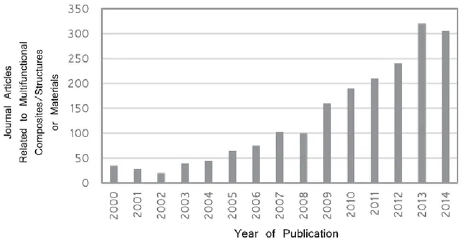
The interest of the scientific community in the new class of materials able to perform several functions is increasing, as it's possible to observe by literature data (Fig.2.3) . As the number of people working in a field increases so does the need for clarification. Many terms are used interchangeably with slightly different meanings. For example, the term ‘‘smart material” is a very lose term whose meaning varies significantly from author to author. Few good suggestions that might be useful was presented by A. Ferreira [1]. He groups Multifunctional materials (MFM), Multifunctional composites (MFC) and multifunctional structures (MFS), will here be group into a broader group named Multifunctional Material Systems (MFMS). The definition of material systems (MS) encompasses materials, composites and structures (Fig.2.4).
29
Figure 2.3 Literature survey on journal articles related to multifunctional composites/ structures/materials in Engineering Village, March 2015.
30
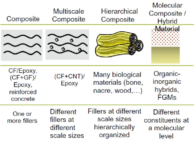
This definition is necessary because one could have, for example, a monofunctional ceramic with a textured surface and an internal structure of a nanolattice. It wouldn’t be correct to call it a MFM because the multifunctionality arises both from the material and the structure. An example of a MFM would be Carbon Nanotubes (CNTs) which inherently have high mechanical strength and electrical conductivity or PZT which can provide both sensing and actuation. An example of a MFC would be epoxy/CF-(Fe powder) (mechanical strength and electrical conductivity), and an example of a MFS would be shark denticles which provide anti-bioufouling and reduce drag. The definition of MFMS, then, encompasses all of these. Other concepts that are going to be mentioned quite a frequently are ‘multiscale’ and ‘hierarchical’ composites (Fig. 2.5). Multiscale composites concern the different sizes of the fillers. For example, a carbon fiber (micromaterial) + carbon nanotube (nanomaterial) reinforcing an epoxy matrix is a multiscale composite. A hierarchical composite concerns the structural organization of the fillers, where fillers/materials are organized in a hierarchical way. For example, filler A is contained inside filler/material B, which is contained inside filler/material C.
31
Figure 2.5Classification of multi-materials according to the types, sizes and organizations of constituents
Another useful concept for distinguishing material systems is that of material integration, that is, how well materials are integrated into one another. One can obtain multifunctionality by integrating various functions in multimaterial systems or single materials. In the former, it can be obtained by the addition of fillers at the nano or microscale such as in (nano-) composites, or multilayer constructs. For single materials it can be obtained at the molecular level such as with several functionalized polymers. Matic [2] and Asp and Greenhalgh [3] have proposed slightly different versions of the same division, a three scale system that Ferreira adapted as a combination of both ideas (Fig.2.6).
32
Figure 2.6Classification of MFMS according to the distinguishing of the constituents: multifunctional structure, multifunctional composite and multifunctional material [1].
The integration of materials goes from not integrated (type I or structure) to integrated but with distinct phases (composite) to fully integrated at the molecular level or type III.
2.3 Current Multifunctional Materials Systems:
2.3.1 Carbon nanomaterials
A lot of research worldwide have recently been focused on Graphene, carbon nano tubes (CNTs) and carbon nanofibers (CNFs). These different spatial configurations of carbon atoms, covalently bonded, (Fig.2.7) combine great mechanical, thermal and electrical properties. Liu et al. [4] have predicted from first principles that this material has the highest
specific stiffness and strength of any known material. Many papers had presented the mechanical characterization of these carbon nanomaterials [5–12] which unfortunately have seen highly variable results due to the difficulties in performing the required tests at the nanoscale, forcing many scientists to resort to indirect ways of measuring. If we were to take a few representative values, CNTs would have 1 TPa < E < 1.8 TPa and 11 < σ𝑟< 150 GPa
33
[5] and would be best thermal conductors currently known having a maximum thermal conductivity of 6600 W/ mK for an individual SWCNT and >3000 W/mK for an individual MWCNT, which is at least twice of diamond’s, and a maximum electrical conductivity of ~300 MS/m for SWNT and >0.1 MS/m for MWNT while revealing superconducting properties at low temperature [13]. Moreover thanks to the fact that CNTs, graphene and CNFs are of a very small size, they are susceptible of reaching far greater surface area to volume ratio (A/V) than micro fillers. Furthermore both CNTs and graphene have either very low (<<1) or very high (>1) aspect ratio which also further increases their A/V ratio (Fig. 2.8). This ratio is one of the main reasons to develop nanocomposites; a high interface region means high adhesion and high efficient transfer of stress across the composite components. This also means that for the same desired effect, a less amount is required of the filler with higher A/V.
Figure 2.7 (a) carbon nano wall or graphene; (b) single walled CNT; (c) multi walled CNT; (d) carbon nano fiber. Adapted from [14].
34
Figure 2.8 Variation of the ratio of surface area/volume (A/V ratio) against aspect ratio l/d and (b) A/V ratio for a cylinder with its radius and height [1].
For the reasons explained before, i.e. extremely good mechanical, electrical and thermal properties and high A/V ratio, there is a strong interest in reinforcing materials with carbon nanomaterials to enhance their properties. This interest can also be attributed to the fact that fiber-reinforced polymer matrix composites, such as glass and carbon fiber, can also be reinforced by these carbon nanomaterials resulting in a multiscale composite with even better properties. Moreover different materials benefit, in different ways, from being reinforced with carbon nanomaterials. Polymers see greatly improved thermal and electrical conductivity as well as increases in strength and elastic modulus when reinforced with graphene, CNTs or CNFs [12,15–18]. Composites of ceramic matrices see an increase in toughness and electrical and thermal conductivity [19]. Metal matrices, most commonly based on Al, Mg, Cu and Ni, have been reported to have increased resistance to corrosion, stiffness and strength [20-22]. Some representative examples can be seen in Fig. 2.9.
35
Figure 2.9 Electrical conductivity as a function of SWCNT mass fraction in a SWCNT-polycarbonate composite. The dashed lines represent the minimum conductivity necessary for the specified functions [23]; (b) Electrical conductivity as a function of graphene volume fraction in a graphene-alumina composite. Adapted from [19]; (c) Thermal conductivity of
epoxy-based composites as a function of filler volume fraction for carbon black (CB), graphitic micro particles (GMP), nanoplatelets (GNP) and single walled CNTs (SWCNT). Adapted from [24]; (d) Stress–strain curve for a nanocomposite of
PA6 polymer matrix and different CNT filler concentrations, adapted from [25].
Given than the most used composites have polymers as matrices, in aircrafts where electrical conductivity is needed in certain parts to transfer electricity from thunders, the poor conductivity of polymers has to be compensated by the addition of more parts, being the sole function is to transfer lightning strikes’ electricity. Polymer matrix nanocomposites with carbon-based fillers are being investigated as a possible replacements for regular polymers typically used in composites’ matrixes.
36
2.3.2 Piezoelectrics
Piezoelectric materials are materials that generate an electric potential in response to an applied mechanical stress, the direct piezoelectric effect, which can be used for sensing or energy harvesting. On the other hand, when applied an electric field to the material it will either change shape or generate mechanical stress, inverse piezoelectric effect, which can be used for actuation and shape control. This means that if we apply a force to a piezoelectric material, it will develop a positive charge on one end and a negative charge on the other end. If we connect the two ends, current flows. Piezoelectric materials are capable of actuating or sensing at frequencies from about 1 Hz to the MHz range with relatively linear behavior. Moreover, they have high stiffness which provides them with strong voltage dependent actuation.
The most used piezoelectric materials are polycrystalline ceramic (PZT, PbTiO3, BaTiO3), single crystals (SiO2, LiNbO3, LiTaO) and polymeric (PVDF, co-polymer) and they take the form of monolithic, thin films [26], wafers [27] and (nano)fibers/wires, [28–33] which can be hollow [34–36] and arranged as macro and active fiber composites [37,38] (MFCs1 and AFCs) or 1–3 Composites. The piezoelectric ceramics are more brittle but have larger actuating forces, whereas the piezoelectric polymers withstand higher deformations and so are better fit for shape hanging applications or irregularly shaped parts. Traditionally, the ceramics have been the most used due to low cost, ease of manufacturing, high coupling efficiency, chemically inertness, high operating temperature and high sensitivity (for sensing). However, ceramics are very brittle and therefore requires extra care when being handled. Furthermore they also have poor conformability to curved surfaces generally requiring extra manufacturing steps in order to be used. The fragility of the piezoceramics has been partially overcome, while also increasing the flexibility of the material, by having them in the form of fibers. Typically, crystalline materials have much higher specific strengths in the form of fiber
37
because the volume fraction of flaws diminishes. Then, by embedding those fibers in a tough polymer-matrix we can increase toughness and flexibility of the composite [39].
A good example was developed by Lin and Sodano [40,41] which create piezoelectric structural fibers that can be laid up in a composite material giving it sensing, actuation and load bearing capacity. The structural fiber was made of a piezoelectric material as an interface between an interior carbon fiber and an exterior piezoelectric material, as illustrated in fig. 2.10a. Guillot et al. [42] also developed a TEFLON-FEP coated PZT hollow fiber for sensing and energy harvesting purposes (fig. 2.10b) revealing a flexibility that wouldn’t be possible had it not been coated (Fig.2.10c) and producing twice as much energy density as the current state of the art Multifunctional Composites (MFCs).
Figure 2.10 (a) Hybrid structural-actuating fiber [40]; (b) one mm diameter hollow PZT fiber coated by Teflon-FEP (c) in bending. Adapted from [42].
Using the inverse piezoelectric effect, it is possible to use piezoelectric materials for actuation. MFCs are composed of unidirectionally aligned rectangular piezoceramic fibers bonded by a polymeric matrix, and sandwiched between interdigitated electrodes (Fig.2.11). This arrangement of electrodes exploits the d33 electromechanical coupling allowing for greater efficiency. Because they are thin and flexible, they can easily be coupled to the surface of other parts, and allow for several actuation types (Fig.2.12).
38
Figure 2.11 Constitution of a typical AFC and a typical MFC. Adapted from [43,44].
Figure 2.12 (a) Picture of an MFC showing its high flexibility [45]; (b) MFCs’ work modes. Adapted from [46].
Li et al. [47] have presented an approach for increasing aerodynamic performance, such as increasing lift, reducing drag and improving roll performance, by using several MFCs distributed on the aircraft wing surface that control the wing’s mechanical deformations.
39
2.3.3 Shape memory materials
Shape memory materials (SMMs) are a type of SRMs that respond to thermal, pressure and magnetic field. For example, Shape memory alloys (SMAs) are metallic alloys that can reversibly recover permanent strains when subjected to a specific stimulus. This recovery occurs when the SMA goes back from the malleable martensite phase to the very stiff austenite phase. SMAs can provide a very lightweight alternative to conventional actuators such as pneumatic, hydraulic or motor-based, since they are outstanding in terms of power/weight ratio over other types of actuators.
SMAs are used in morphing aerospace structures quite extensively [48]. Sofla et al. [49] reviewed aircraft wing morphing technologies while also developing a shape morphing aircraft wing using an antagonistically positioned SMAs material which flex the wing (Fig. 2.13). In the trailing edges of some jet engines chevrons are used for noise reduction. BOEING developed a device known as variable geometry chevron to reduce take-off noise and increase cruise efficiency which is actuated by NiTi SMAs flexures [50] (Fig. 2.14).
Figure 2.13 Bending achieved in a prototype aircraft wing by heating of SMA strips. (a) Un-morphed and (b) morphed [49].
40
Figure 2.14 Variable geometry chevron developed by Boeing, adapted from [50].
In SMAs, it is also possible to program multiple memory shapes, and this has seen a surge of interest in the recent years. This can be done using a new process known as multiple memory material technology [51] or by combining SMAs with other materials such as SMPs (Shape memory polymers) [52] resulting in a SMH with greater functionality.
Comparatively to SMAs, SMPs have many important advantages such as lower cost, density and easier processing, among others. Most studies concerning SMPs are about the thermoplastics ones, which have relatively poor thermal and mechanical properties (e.g. temperature, moisture and chemical resistance), so they may not be able to meet many requirements for multifunctional structural materials. However, thermosets, as well as thermoplastic SMPs reinforced with CF and CNTs, and other fillers are in development and show promise [53,55].
Like SMAs, SMPs also find applications in aerospace. The aerodynamic performance of aircrafts is designed for specific flight conditions, e.g. cruise for long range airliners, meaning that whenever the plane is not at the condition it was optimized for, efficiency is going to drop. For this reason, there is great interest in expanding the optimal flight conditions, which could be obtained through morphing parts of the aircraft giving it the ability to change its
41
geometry during flight. There are several attempts at implementing the concept of morphing wings [56]. Two examples concerning the use of SMPs as the actuation mechanism are shown in (Fig.2.15a and b). Due to their shape morphing ability, SMPs are also being studied for use in deployable structures [57]. The main advantage of using SMPs for space applications is that it could greatly reduce the volume, weight, and cost of the structure compared with traditional self-deploying techniques. For example, Keller et al. [58] have developed a deployable radio frequency reflector comprised of SMP-based composites claiming it is much more mechanically simpler and lighter than its conventional competitors (Fig.2.15c–d).
Figure 2.15 SMPs application in aerospace, so far mainly for actuation: (a) Prototype of a morphing wing unmanned combat air vehicle by Lockheed Martin [53]; (b) Conductive SMP for morphing wing, adapted from [58]; (c) A SMP composite reflector in its pre-deformed (up) and recovered (down) shape; (d) illustration of the structure of the reflector
42
2.3.4 Carbon fiber reinforced composites for energy storage and sensing
The idea of adding energy storage function to high performance structural materials has been gaining increased attention.has the interest in better batteries. Eric Jacques, a researcher in and aerospace engineering at KTH, has mentioned how carbon fiber can fill two functions in an electric car: as a lightweight composite reinforcement material for the car’s body, and as an active electrode in lithium ion batteries. He says carbon fiber offers a viable alternative to graphite. Lithium can be inserted into the carbon fiber microstructure and the carbon fiber acts as a good conductor [59].
Drayson Racing Technologies and Lola first presented the Lola Drayson B12/69EV, an electric racing car that uses a composite structural battery to aid the main battery for powering (Fig.2.16) [60]. Even though the way the composite was achieved in the Lola Drayson, and many others, are hidden inside the R&D of industries, other researches might give a hint due to research of their own. Pereira [61] obtained a CF/epoxy with energy storage function by embedding thin film lithium energy cells within the CF layers. The strength and stiffness of the carbon/epoxy laminate was not significantly changed, and there was no abnormalities in the energy cells’ charging and discharging processes when the composite was mechanically loaded to up to 50% of its ultimate tensile strength.
43
Figure 2.16 Lola Drayson B12/69EV electric racing car with nickel-based and CF structural-batteries [60].
2.3.5 Self-healing materials
Self-healing materials are materials that are capable of selfrepairing damage without human intervention. To help categorize these materials we can divide them into classes (Fig.2.17). The first is related to how the healing mechanism is triggered. If it needs an external stimulus such as light or heat they’re called non-autonomic, whereas if the damage itself is enough to trigger the healing they’re called autonomic. The second is related to how the healing mechanism is or isn’t part of the material. In extrinsic self-healing, the process requires external, specifically brought in by vascules, or embedded in micro or nanocapsules materials for the self-healing to occur. Intrinsic self-healing, on the other hand happens when the matrix itself has the ability to provide healing function. The self-healing ability has been studied in for ceramics, metals and polymers. A way to quickly perceive the difference in difficulty of implementing the self-healing functions on these three material types is through the temperatures at which the mechanism of healing occurs. Low temperatures for polymers and
44
their composites (<120 °C) and high temperatures for metals (<600 °C) and ceramics (>800 °C).
Figure 2.17 Classification of self-healing materials according to their autonomy and healing mechanism integration.
Self-healing finds most interest, by far, in polymer matrix composites. In them, internal micro cracks/damages during their lifetime cycle are very hard to detect and to repair. The current way to deal with this is to adopt conservative designs, which lead to overweight structures that do not utilize the full potential of fiber reinforced polymer matrixes. The development of self-healing in thermosets has followed a distinctly different route than that of thermoplastics. While for thermoplastics healing is generally associated with the high chain mobility which allows a softening and flow of material across a damaged interface that occurs upon heating, for thermosets such is not possible because their typical cross-link network prevents the polymer chains from diffusing through the material when heated above the Tg and instead the material degrades. Because of this, for thermosets most of the methods developed so far are extrinsic, requiring the use of a healing agent to mend the cracks. The research is presently focused on discovering the best distribution method and healing agent as well as the
45
possibility of mixing with others. As for the distribution method of the healing agent the most well-known are:
Healing agent sealed in discrete micro-capsules for one time local healing when capsules are ruptured [62] (Fig.2.18a). This only works for micron-sized cracks with limited size and the healing process ceases once the healing agent is used;
Hollow fiber embedment, generally glass fibers but more recently CNTs have also been researched [63] (Fig.2.18b). This method allows for multiple healing to occur and for larger cracks, and also can increase structural performance as the fibers also have load bearing capacity;
A bio-inspired network of capillaries in which healing agen flows inside for multiple local healing events (Fig.2.18c) [64,65];
Brownian motion induced polymer chain crawling has also been applied for self healing but with limited achievement.
Even if self-healing occurs and is shown to totally restore strength, it might be useful to have indications of the location and severity of the damage. Such can be accomplished if the healing agent is mixed with a fluorescent dye like Pang and Bond [70] did.
As the literature review showed, self-healing currently almost exclusively deals with repairing the structural function of materials. When damage occurs in multifunctional composites, several functions can be impaired at the same time, which raises the need for the healing ability to repair them as well.
46
Figure 2.18Fig. 62. (a) Illustration a self-healing mechanism based on a microencapsulated healing agent embedded in the matrix. When a crack occurs, the healing agent fills it cracks by capillary action, and, mixed with the catalyst, is polymerized and bonds the crack faces together; (b) illustration of healing mechanism in hollow fiberbased self-healing composites. Adapted from [66] and [67]; (c) Self-self-healing mechanism based on distribution by vasculature; (d)
ESEM image showing ruptured microcapsule [68] (e) Intra-ply shear cracks intercepting hollow glass fibers in a self-healing CFRP laminate [69]; (f) Vascule in an Epoxy/CF laminate[64].
47
2.4 Synthesis of multifunctional nanocomposites
Multifunctional nanocomposites received a great deal of attention due to their synergy or enhanced properties compared to their base counterparts. In the field of multifunctional nanomaterials, considerable effort has been centered on the noble metal-based systems by immobilizing noble metal onto diverse inorganic/organic supports to obtain the desired functional nanomaterials. In addition, effort has been made in loading noble metals on semiconductor metal oxides such as TiO2 and highly conductive nanomaterial such as CNTs using any surfactant or linkers [71].
It is well known that at nanoscale, the physical, chemical, and biological properties of materials are very different from their corresponding bulk counterpart because of the quantum confinement. For instance, gold and silver nanoparticles are characterized by their strong ability to absorb visible light at certain wavelengths, which depend on the size and shape of the nanomaterials. Solids with nanoparticle size cannot be prepared by traditional methods simply because the reactants are not mixed on the atomic scale. For this reason alternative methods, e.g., hydrothermal, sol–gel, Pechini, CVD, electrospinning, and microwave, have been evaluated in order to achieve atomic-scale mixing of reactants, in gas, liquid, or even solid phases. Although these are low-temperature methods, nevertheless, high-temperature processing may be required, especially for ceramic-based nanomaterials. These methods enable the final product to be homogenous nanosized materials with narrow particle size distribution. The appropriate methodologies for the preparation of these multifunctional nanomaterials are depicted in Table 2 [72] and they will be described below.
48
Table 2 Methodologies for the preparation of multifunctional nanomaterials
Hydrothermal synthesis
Hydrothermal synthesis is one of the prominent methods employed to precipitate single/multiphase metal/semiconductor metal oxides directly from their corresponding homogeneous/heterogeneous solution. Hydrothermal synthesis is a single-step process preferred for preparing several single/multiphase oxides and phosphates [73-76]. Due to its simplicity and versatility, hydrothermal synthesis is also being used to grow single crystals ranging from emeralds, rubies, quartz, to alexandrite. The technique is also being employed to obtain nanomaterial for energy as well as environmental applications ranging from dye-sensitized solar cells to catalysis [77-78].
49 Sol–gel synthesis
In sol–gel synthesis, a colloidal solution (sol) is being used to prepare a compound consisting of a metal or metalloid element surrounded by appropriate ligands (gel). This process results in the fabrication of variety of nanocrystalline elemental, alloy, and composite metal/semiconductor metal oxides. The sol–gel synthesis provides greater control in the process parameters, resulting in the synthesis of a variety of metal/semiconductor metal oxides [79].
Polymerized complex method (Pechini process)
A wet chemical method using polymeric precursor based on the Pechini process has been employed to prepare a wide variety of ceramic oxides. The process offers several advantages for processing ceramic powders such as direct and precise control of stoichiometry, uniform mixing of multicomponents on a molecular scale, and homogeneity. The method is being widely used for the synthesis of dielectric, fluorescent, magnetic materials, high-temperature superconductors, and catalysts. The method is also preferred for the deposition of oxide films as coatings, for instance, nanostructured electrode in dye-synthesized solar cells and lithium ion battery [80-82].
Chemical vapor deposition
Chemical vapor deposition (CVD) can deposit a film of solid material on a heated surface from a chemical reaction in the vapor phase. The versatile process can result in nano/microstructured coatings, powders, fibers, as well as multiphase compounds from metals, metal oxides, as well as nonmetallic elements such as carbon and silicon [83-85]. The advantage of CVD includes high throughput due to high deposition rate, as well as fabrication of single/multiphase nanomaterials. CVD process has been given enormous attention, owing to the possibility of mass production of nanomaterials; nevertheless, the mechanism of powder synthesis kinetics is still not completely known for this technique.
50 Microwave synthesis
The applicability of microwave processing spans over a number of fields, ranging from food processing to medical and chemical applications. A major area of research in microwave processing includes microwave material interaction, microwave equipment design, new material development, sintering, joining, and modeling. As microwave processing offers uniform heating at a lower temperature, it is being successively utilized in the fabrication of ceramics as well as carbon fibers at low temperature and time [86-87].
51
2.5 Chapter 2 References
[1] A.D.B.L. Ferreira et al. / Composite Structures 151 (2016) 3–35. [2] Matic P, 5053. Bellingham, Wash: SPIE; 2003. p. 61–9.
[3] Asp LE, Greenhalgh ES. Multifunctional composite materials for energy storage in structural load paths. [Slide Presentation]; 2012.
[4] Liu M, et al., ACS Nano 2013;7:10075–82.
[5] Page CD. Characterization of multifunctional carbon nanotube yarns: in-situ strain sensing and composite reinforcement 3586178 Ph.D. North Carolina State University, Ann Arbor; 2013.
[6] Zuberi MJS, Esat V., Compos B Eng 2015;71:1–9. [7] Sakharova NA, et al., Compos B Eng 2015;75:73–85. [8] Rafiee R, Moghadam RM., Compos B Eng 2014;56:435–49. [9] Shokrieh MM, Rafiee R., Mech Compos Mater 2010;46:155–72. [10] Allaoui A, et al., Compos Sci Technol 2002;62(11):1993–8.
[11] Hu Z, Lu X. Chapter 8 – mechanical properties of carbon nanotubes and graphene. In: Iijima KT, editor. Carbon nanotubes and graphene. Oxford: Elsevier; 2014. p. 165–200. [12] Du JH, Cheng HM., Macromol Chem Phys Jun 2012;213:1060–77.
[13]Zapata-Solvas E, et al., J Eur Ceram Soc Sep 2012;32:3001–20. [14] Kang I, et al., Compos Part B: Eng 2006;37:382–94.
52 [16] Coleman JN, et al., Carbon 2006;44:1624–52. [17] Tjong SC., Mater Sci Eng: R: Rep 2006;53:73–197. [18] Lin Y, et al., Compos B Eng 2015;76:31–7.
[19] Porwal H, et al. Appl Ceram Nov 2013;112:443–54. [20] Ovid’ko IA., Rev Adv Mater Sci 2014;38:190–200. [21] Tjong SC., Mater Sci Eng: R: Rep 2013;74:281–350. [22] Bakshi SR, et al., Int Mater Rev 2010;55:41–64.
[23] Moniruzzaman M, Winey KI., Macromolecules 2006;39:5194–205. 2006/08/01. [24] Yu A, et al., J Phys Chem C 2007;111:7565–9. 2007/05/01
[25] Liu, Phang IY, et al., Macromolecules 2004;37:7214–22. 2004/09/01. [26] Muralt P, et al., MRS Bull 2009;34:658–64.
[27] Giurgiutiu V, Zagrai AN., J Intell Mater Syst Struct 2000;11:959–76. [28] Cook AC, Vel SS., Eur J Mech A Solids 2013;40:11–33.
[29] Cook AC, Vel SS., Compos Struct 2012;94:322–36. [30] Huang T, et al., Nano Energy 2015.
[31] Ramdayal, Balasubramanian K., Defence Sci Journal 2013;63:331–9. [32] Zhang M, et al., Nano Energy 2015.
[33] Nilsson E, et al., Proc Eng2014;87:1569–72.
53
[35] Brei D, Cannon BJ., Compos Sci Technol 2004;64:245–61. [36] Guillot FM, et al., J Eng Fibers Fabr 2013;8:75–81.
[37] Chen Y, et al., In: SPIE, Smart structures and materials 2006: smart structures and integrated systems, San Diego; 2006.
[38] Bent AA. Active fiber composites for structural actuation [Doctor of Philosophy], Aeronautics and Astronautics, Massachusetts Institute of Technology; 1997.
[39]Lin X-J, et al., Trans Nonferrous Met Soc China 2013;23:98–107. [40] Lin Y, Sodano HA., Compos Sci Technol 2008;68:1911–8. [41] Lin Y, Sodano HA., . Adv Funct Mater 2009;19:592–8. [42] Guillot François M, et al., J Eng Fibers Fabrics 2013;8. [43] Brett Williams R et all., Modal Analysis Conference; 2002. [44] Kovalovs A, et al., J Phys: Conf Ser 2007;93:012034.
[45] NASA’s Langley Research Center. <https://spinoff.nasa.gov/Spinoff2007/ip_9.html>; 2007.
[46] Smart material. <http://www. smart-material.com/MFC-product-main.html>; 2015. [47] Li M., Sci China Ser E: Technol Sci 2011;54:395–402.
[48] Calkins FT, Mabe JH., J Mech Des 2010;132:111012. [49] Sofla AYN, et al., Mater Des 2010;31:1284–92. [50] Oehler SD, et al., Smart Mater Struct 2012;21:094016. [51] Khan MI, et al., Adv Eng Mater 2013;15:386–93.
54 [52] Ghosh P, et al., Mater Des 2013;44:164–71. [53]Leng J, et al., Prog Mater Sci 2011;56:1077–135. [54] Meng H., Polymer 2013;54:2199–221.
[55] Lu HB, et al., Nanosci Nanotechnol Lett Sep 2014;6:772–86. [56] Thill C, et al., Aeronaut J 2008;112:117–39.
[57] Leng J-S, et al., Yuhang Xuebao/J Astronaut 2010;31:950–6.
[58] K. Philip, et al., 47th AIAA/ASME/ASCE/AHS/ASC Structures, Structural Dynamics, and Materials Conference, American Institute of Aeronautics and Astronautics, 2006.
[59] <http://www.kth.se/en/aktuellt/nyheter/de-gor-batterier-avkolfiber-1.480780>
[60] The Conservative Thinkers Blogspot. Lola Drayson B12/69EV electric racing car launched, available: Lola Drayson B12/69EV electric racing car launched; 2014.
[61] Pereira AM. Energy-storage multifunctional composites 3405614 Ph.D. University of California, Los Angeles, Ann Arbor; 2009.
[62] Kirkby EL, et al., Polymer 2009;50:5533–8.
[63] Lanzara G, et al., Nanotechnology 08/19 2009;20:5533–8. p. 335704 (7 p.).
[64] Norris CJB, et al. Healing of low-velocity impact damage in vascularised composites. vol. 44; 2013. p. 85.
[65] Hugo RST, et al., first international conference on self healing materials, Noordwijk aan Z ee,The Netherlands; 2007
55
[67] Wu DY, et al., Prog Polym Sci 2008;33:479–522.
[68] Trask RS, et al., Bioinspiration Biomimetics Mar 2007;2:P1–9. [69] Trask RS, et al., J R Soc Interface 2007;4:363–71.
[70] Pang JWC et al., Compos Part A Appl Sci Manuf 2005;36:183–8.
[71] Jose et al., Journal of the American Ceramic Society (2009), 92(2), 289–301.
[72] Sahay et al. International Journal of Mechanical and Materials Engineering 2014, 9:25 [73] Dai et al., Nano Letters (2009), 9(6), 2455–2459
[74] Fang et al., Small (2006), 2(5), 612–615. [75] Ye et al., Small (2010), 6(2), 296–306.
[76] Ji et al., Research Bulletin (2009), 44(4), 768–774.
[77] Hsu et al., Applied Physics Letters (2008), 92(13), 133507.
[78] Zhou et al., European Journal of Inorganic Chemistry (2010), 5, 729–734.
[79] Leventis et al., Journal of the American Chemical Society(2009), 131(13), 4576–4577. [80] Sahay et al., Journal of Solid State Chemistry (2012a), 186, 261–267.
[81]Sahay et al., Journal of Physical Chemistry C (2012b), 116(34), 18087–18092. [82] Suresh Kumar et al., J. Phys. D: Appl. Phys. (2012), 45(26), 265302 (1-5).
[83] Hitchman and Tian, Journal of Electroanalytical Chemistry (2002), 538, 165–172. [84] Iguchi et al., Topics in Catalysis (2009), 52(6–7), 563–570.
56
[85] Mills et al., Journal of Photochemistry and Photobiology A-Chemistry (2002), 151(1–3), 171-179.
[86] Reddy et al., Catalysis Letters (2009), 130(1–2), 227–234.
57
3. Electrospinning: Process and Applications
3.1 Introduction
It has been view that when the diameters of polymer fiber materials are shrunk from micrometers to submicrons or nanometers, there appear several amazing characteristics such as very large surface area to volume ratio (this ratio for a nanofiber can be as large as 103 times of that of a microfiber), flexibility in surface functionalities, and superior mechanical performance (e.g. stiffness and tensile strength) compared with any other known form of the material. These outstanding properties make the polymer nanofibers to be optimal candidates for many important applications. A number of processing techniques such as drawing, template synthesis, phase separation, self-assembly, electrospinning, etc. have been used to prepare polymer nanofibers in recent years.
The drawing is a process similar to dry spinning in fiber industry, which can make one-by-one very long single nanofibers. However, only a viscoelastic material that can undergo strong deformations while being cohesive enough to support the stresses developed during pulling can be made into nanofibers through drawing. The template synthesis, as the name suggests, uses a nanoporous membrane as a template to make nanofibers of solid (a fibril) or hollow (a tubule) shape. The most important feature of this method may lie in that nanometer tubules and fibrils of various raw materials such as electronically conducting polymers, metals, semiconductors, and carbons can be fabricated. On the other hand, the method cannot makeone-by-one continuous nanofibers. The phase separation consists of dissolution, gelation, extraction using a different solvent, freezing, and drying resulting in a nanoscale porous foam. The process takes relatively long period of time to transfer the solid polymer into the nano-porous foam.
58
The self-assembly is a process in which individual, pre-existing components organize themselves into desired patterns and functions. However, similarly to the phase separation the self-assembly is time-consuming in processing continuous polymer nanofibers. Thus, the electrospinning process seems to be the only method which can be further developed for mass production of one-by-one continuous nanofibers from various polymers. Electrospinning has emerged as a powerful technique for producing high strength fibers due to its versatility, ease of use, ability to align structures and control fiber diameters. Some of these unique features cannot be otherwise achieved by conventional fiber processing techniques mentioned above. Another merit is that under the influence of an electric field, electrospinning self-assembles dispersed fillers along the axial direction such that composites can be formed by imposing additional spatial confinement to the polymer chains. These reinforced fibers display superior properties and function as basic building blocks for the fabrication of high strength structures using a bottom-up approach. For example, carbon nanotubes (CNTs) and carbon black (CB) particles are among the commonly used fillers which are dispersed within the fibers to mimic the functionality of silk fibers for high strength and toughness applications.
3.2 History of electrospinning
The origin of electrospinning as a viable fiber spinning technique can be traced back to the early 1930s. In 1934, Formhals patented his first invention relating to the process and the apparatus for producing artificial filaments using electric charges [1]. Though the method of producing artificial threads using an electric field had been experimented with for a long time, it had not gained importance until Formhals’s invention due to some technical difficulties in earlier spinning methods, such as fiber drying and collection. Formhals’s spinning process consists of a movable thread collecting device to collect the threads in a stretched condition, like that of a spinning drum in the conventional spinning. Formhals’s process was capable of

![Figure 2.6 Classification of MFMS according to the distinguishing of the constituents: multifunctional structure, multifunctional composite and multifunctional material [1]](https://thumb-eu.123doks.com/thumbv2/123dokorg/4519454.34860/32.892.132.804.105.398/classification-according-distinguishing-constituents-multifunctional-structure-multifunctional-multifunctional.webp)
![Figure 2.11 Constitution of a typical AFC and a typical MFC. Adapted from [43,44].](https://thumb-eu.123doks.com/thumbv2/123dokorg/4519454.34860/38.892.141.770.115.378/figure-constitution-typical-afc-typical-mfc-adapted.webp)
![Figure 2.13 Bending achieved in a prototype aircraft wing by heating of SMA strips. (a) Un-morphed and (b) morphed [49]](https://thumb-eu.123doks.com/thumbv2/123dokorg/4519454.34860/39.892.248.686.733.1063/figure-bending-achieved-prototype-aircraft-heating-morphed-morphed.webp)
![Figure 2.15 SMPs application in aerospace, so far mainly for actuation: (a) Prototype of a morphing wing unmanned combat air vehicle by Lockheed Martin [53]; (b) Conductive SMP for morphing wing, adapted from [58]; (c) A SMP composite reflector in its pr](https://thumb-eu.123doks.com/thumbv2/123dokorg/4519454.34860/41.892.135.798.451.1055/application-aerospace-actuation-prototype-lockheed-conductive-composite-reflector.webp)
![Figure 2.16 Lola Drayson B12/69EV electric racing car with nickel-based and CF structural-batteries [60]](https://thumb-eu.123doks.com/thumbv2/123dokorg/4519454.34860/43.892.178.761.118.451/figure-lola-drayson-electric-racing-nickel-structural-batteries.webp)


