Analisi di pre-test della campagna sperimentale CIRCE/HERO con codici
di sistema
Descrittori
Tipologia del documento: Rapporto Tecnico
Collocazione contrattuale:
Accordo di programma ENEA-MSE su sicurezza nucleare e
reattori di IV generazione
Argomenti trattati:
Generation IV reactors, Tecnologia del piombo,
Termoidraulica dei reattori nucleari
Sommario
Nell’ambito dell’attività PAR 2016 in sinergia con i progetti H2020 SESAME e MYRTHE si è costruita ed installata la sezione di prova HERO. Tale sezione di prova rappresenta, in scala, il progetto di riferimento del generatore di vapore dell’LFR. Inoltre, in ambito PAR 2015, sono state sviluppate e documentate le nodalizzazioni dell’impianto CIRCE/HERO con i codici RELAP5/Mod3.3 e RELAP5-3D©. Il presente report è un contributo alla progettazione della campagna sperimentale CIRCE/HERO, rilevante per la validazione di codici di sistema e CFD. L’attività è estata condotta utilizzando il codice RELAP5-3D, modificato dall’Università di Roma per adeguare le proprietà termofisiche del LBE con quelle più aggiornate e riconosciute internazionalmente (i.e. OECD/NEA). Lo scopo è di progettare un esperimento che riproduca la transizione da circolazione forzata a circolazione naturale. Dapprima sono state fatte delle analisi al fine di determinare le migliori condizioni iniziali per il transitorio. Successivamente, è stato valutata la dinamica del sistema, in condizioni di potenza di decadimento e circolazione naturale, al variare della portata d’acqua del secondario tra 0-20% della portata nominale.
Note
Autori: V. Narcisi, P. Lorusso, F. Giannetti (UNIROMA), A. Del Nevo, M. Tarantino (ENEA)
Copia n. In carico a:
1
NOMEFIRMA
0
EMISSIONE01.12.2017
NOMEA. Del Nevo
I. Di Piazza
M. Tarantino
FIRMATitle: Pre-tests analyses of CIRCE/HERO
experimental campaign using system codes
Project:
ADP ENEA-MSE PAR 2016Distribution
P
UBLICIssue Date
01.12.2017
Pag.
R
ICERCAS
ISTEMAE
LETTRICORef.
ADPFISS-LP2-151Rev. 0
2 di 35
List of revisions
Revision Date Scope of revision Page
Table of contents
List of revisions ... 2
List of figures ... 4
List of tables ... 5
1 Introduction ... 6
2 The CIRCE-HERO Test Facility ... 6
2.1 Secondary system ... 11
3 RELAP5-3D© modelling ... 12
4 Pre-Test Calculations ... 16
4.1 Identification of full power steady state conditions ... 16
4.2 Transient analysis ... 21
4.2.1 Transient Test 1 ... 23
4.2.2 Comparison of the transient tests ... 28
5 Conclusions... 33
Title: Pre-tests analyses of CIRCE/HERO
experimental campaign using system codes
Project:
ADP ENEA-MSE PAR 2016Distribution
P
UBLICIssue Date
01.12.2017
Pag.
R
ICERCAS
ISTEMAE
LETTRICORef.
ADPFISS-LP2-151Rev. 0
4 di 35
List of figures
Figure 1: CIRCE isometric view ... 7
Figure 2: CIRCE-HERO test section ... 8
Figure 3: FPS hexagonal bundle ... 8
Figure 4: FPS arrangement ... 9
Figure 5: HERO-SGBT: double wall wrap ... 10
Figure 6: HERO steam generator bayonet tube ... 11
Figure 7: Pre-heater: spiral geometry ... 12
Figure 8: Secondary loop... 12
Figure 9: Region #1: mono-dimensional scheme ... 14
Figure 10: Region #2: multi-dimensional component ... 15
Figure 11: FPS nodalizzation scheme ... 16
Figure 12: LBE mass flow rate ... 18
Figure 13: LBE temperatures ... 18
Figure 14: FPS temperatures ... 19
Figure 15: pool temperature ... 20
Figure 16: representative section ... 21
Figure 17: TrT 1 – LBE mass flow rate ... 24
Figure 18: TrT 1 – LBE temperatures ... 25
Figure 19: TrT 1 – Thermal stratification ... 26
Figure 20: TrT1 – Temperature evolution ... 27
Figure 21: TrT1 – FPS temperature evolution ... 28
Figure 22: Comparison – LBE mass flow rate ... 29
Figure 23: Comparison – FPS temperatures ... 30
Figure 24: Comparison – SG temperatures... 30
Figure 25: Comparison – Thermal Stratification ... 31
Figure 26: TrT3 – Temperature evolution ... 32
List of tables
Table 1: CIRCE S100 main parameter ... 7
Table 2: Model dimensions ... 16
Table 3: Full power calculations – boundary conditions ... 17
Table 4: Full power calculations – main results ... 17
Table 5: FW and Ar injection ... 21
Table 6: Compensated power curve ... 22
Title: Pre-tests analyses of CIRCE/HERO
experimental campaign using system codes
Project:
ADP ENEA-MSE PAR 2016Distribution
P
UBLICIssue Date
01.12.2017
Pag.
R
ICERCAS
ISTEMAE
LETTRICORef.
ADPFISS-LP2-151Rev. 0
6 di 35
1 Introduction
In the framework of the Lead-cooled European Advanced DEmonstartion Reactor (LEADER) project, a new concept of Steam Generator (SG) was proposed for ALFRED (Advanced Lead Fast Reactor European Demonstrator). The innovative configuration is the super-heated steam double wall bayonet tube type with leakage monitoring which allows the double physical separation between the primary coolant and the steam-water that flows inside the tubes. This solution permits to increase the safety margin of the nuclear power plant (NPP), reducing the probability of the interaction of the primary and secondary coolant, and the possibility to detect any leakages from the steam-water or the liquid metal, monitoring the pressure inside the separation volume.
In order to investigate and develop the behaviour of the new SG configuration and to provide suitable experimental data for the code validation, ENEA designed and constructed HERO (Heavy liquid mEtal pRessurized water cOoled tubes) test section to investigate a bundle of seven bayonet tubes with an active length of 6 m, in scale 1:1 with the tubes which will comped the ALFRED steam generators.
The main purpose of this report is to carry out the pre-tests for the design of an excperimental campaign aimed at studying the transition between forced an natural circulation and to select one transient suitable for an international benchmark.
2 The CIRCE-HERO Test Facility
CIRCE is a multipurpose pool facility, designed to study innovative heavy liquid metal cooled nuclear system. It consists of a main cylindrical vessel, filled with about 70 tons of molten Lead-Bismuth Eutectic (LBE), which aims to contain different test sections, and two auxiliary tanks, to store liquid metal during the maintenance phases and to host LBE during the transfer phases (see Figure 1). The main parameters of the facility are summarized in Table 1 [1].
The previous test section installed in CIRCE, named ICE (Integral Circulation Experiment), has been upgraded in order to host HERO test section, the innovative SG which consists of seven double wall bayonet tubes with an active length of 6 m (1:1 with ALFRED SG tube length) reproducing, as much as possible, ALFRED steam generator under operational conditions. As shown in Figure 2, HERO (in blues) has been located in the position of the previous heat exchanger (HX), partially contained inside the cylindrical shell of the HX. The primary main flow path is also highlighted in Figure 2. The feeding conduit is the inlet of the test section; the molten LBE enters the unit and it passes through the Venturi-nozzle flow meter, included into the feeding conduit, which measures the mass flow rate of the liquid metal entering the FPS. The fuel pin simulator is the core of the facility which consists of the electrical pin bundle with a nominal thermal power of 1 MW and an active length of 1 m. The bundle (see Figure 3) is composed of 37 electrically heated pins arranged in a wrapped hexagonal lattice with a pitch to diameter ratio equal to 1.8. Each pin is characterized by an outer diameter of 8.2 mm and it provides a thermal power of 25 kW and a heat flux at the pin wall of 1 MW/m2. The relative position between the pins and the wrapper is fixed by three spacer grids which dived the unit in three zones (Figure 4): the bottom mixing zone, the active zone and the upper mixing zone. Moreover, the pins are kept in the correct position with a lower grid, which guarantees the LBE inlet, and an upper grid, acting as FPS cap equipped with penetrations for the pins. The hot LBE exits the heat source (HS), it flows through the release pipe and it moves inside the fitting volume (in green in Figure 2), which connects the FPS with the riser (in yellow), a double wall pipe insulated with the air gap in order to reduce the heat dissipation towards the pool. At the inlet section of the riser, the nozzle of the argon injection system is installed in order to promote the circulation of the primary coolant. The mixture flows upward inside the riser and it is collected into the separator, which is the upper component of the test section. The separator has two function: it creates the expansion volume dedicated to the separation of the hot LBE and the argon gas and guarantees the connection between the riser and the SG. The HERO Steam Generator Bayonet tubes consists of seven double wall bayonet tubes with an active length of 6 m, arranged in a hexagonal bundle. The unit is included inside a double wall wrapper, depicted in Figure 5, which consists of the internal hexagonal wrap and the external cylindrical shroud that allows the insulation of the unit by the air gap. The hot LBE enters the unit through six inlet holes, obtained on the hexagonal shroud and located inside the separator, and flows downward across the free volume between the inner shroud and the tubes. The Figure 6 depicts a schematic view of the bayonet tube; the feed-water enters at the top edge of the slave tube and flows downward reaching the saturation conditions. It is collected in the lower plenum of the tube and flows
upward through the annular volume between the inner and the second tube, reaching the superheated conditions at the end of the active length. Then the steam exits the unit and it is collected inside the steam generator, hydraulically connected with each tube. The volume between the slave tube and the inner tube is filled with an insulator layer in order to prevent the steam condensation on the outer wall of the inner tube. The main features of the unit are the double separation and the leakage monitoring system. The separation between primary and secondary coolant is obtained with the second and the third tube; the volume between these two tubes is filled with pressurized helium, in order to detect any leakages from primary or secondary side by monitoring the helium pressure, and a high conductivity powder to enhance the heat exchange capability. The bayonet tubes are arranged inside the hexagonal shroud with a p/d of 1.42 and they are kept in position by means of five spacer grids [2].
Figure 1: CIRCE isometric view
Table 1: CIRCE S100 main parameter
Parameter Value
Outside Diameter 1200 mm
Wall Thickness 15 mm
Material AISI 316L
Max LBE inventory Electrical Heating Cooling Air Flow Rate Temperature Range Operating Pressure Design Pressure
Nominal Argon Flow Rate
90000 kg 47 Kw 3 Nm3/s 200-550°C 15 kPa (gauge) 450 kPa (gauge) 15 Nl/s
Title: Pre-tests analyses of CIRCE/HERO
experimental campaign using system codes
Project:
ADP ENEA-MSE PAR 2016Distribution
P
UBLICIssue Date
01.12.2017
Pag.
R
ICERCAS
ISTEMAE
LETTRICORef.
ADPFISS-LP2-151Rev. 0
8 di 35
Figure 2: CIRCE-HERO test section
Title: Pre-tests analyses of CIRCE/HERO
experimental campaign using system codes
Project:
ADP ENEA-MSE PAR 2016Distribution
P
UBLICIssue Date
01.12.2017
Pag.
R
ICERCAS
ISTEMAE
LETTRICORef.
ADPFISS-LP2-151Rev. 0
10 di 35
Figure 6: HERO steam generator bayonet tube
2.1 Secondary system
The secondary system is based on a open loop circuit fed by water. The water is pressurized at 180 bar and preheated at 335°C before entering the SGBT unit. It is required approximately 500 kW.
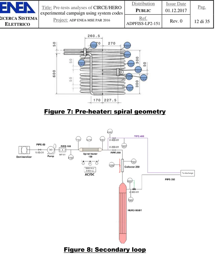
The preheating function is performed by an electrically heated pipe (24 m long) designed in spiral geometry (Figure 7). This component assures the maximum temperature of 450°C. The secondary system is composed of:
The demineralizer;
The pump;
The spiral heater;
The collector;
The HERO SGBT.
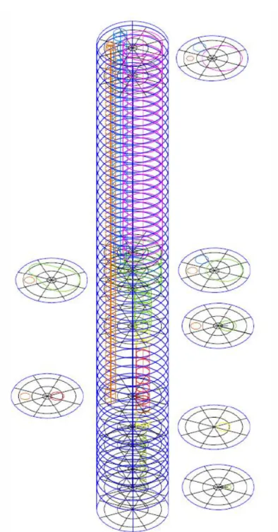
The demineralized water is pressurized by a volumetric pump (with oscillation reducer) connected with a control valve. The pressurized water is sent to the pre-heated component to increase its temperature and then it is collected in the collector. This component is designed in order to achieve, as uniform as possible, distribution of the feed-water to the seven bayonet tubes (two grids with no coaxial holes are provided). Finally, the water enters in HERO SGBTs where it is heated and evaporated. Figure 8 shows a schematic view of secondary loop [3].
Title: Pre-tests analyses of CIRCE/HERO
experimental campaign using system codes
Project:
ADP ENEA-MSE PAR 2016Distribution
P
UBLICIssue Date
01.12.2017
Pag.
R
ICERCAS
ISTEMAE
LETTRICORef.
ADPFISS-LP2-151Rev. 0
12 di 35
Figure 7: Pre-heater: spiral geometry
Figure 8: Secondary loop
3 RELAP5-3D
©modelling
RELAP5-3D© is the last version of R5 series, which was developed to simulate accidental thermal-hydraulic transient in light water-cooled reactors. The main improvement of R5-3D, from previous versions, are the capability to simulate multi-dimensional component and the addition of new working fluids, including HLM [4]. The validated R5-3D nodalization scheme of CIRCE-ICE test facility [5] [6] have been upgraded in order to carry out pre-test analysis of HERO experimental campaign. Three are the main differences between the test sections: HERO SGBTs substitutes for previous HX, the holes on the cylindrical shell of the FPS are closed, in order to limit the heat losses between the HS and the cold pool, and the DHR system is removed. The nodalizzation scheme consists of two macro regions, coupled to simulate the global facility: a
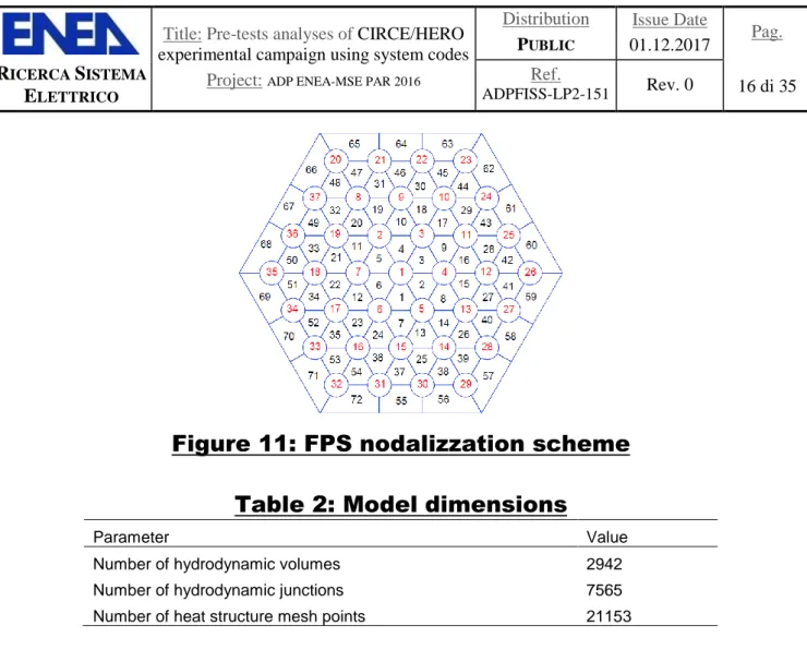
mono-dimensional model to simulate thermal-hydraulics of the primary main flow path (see Figure 9) and a three-dimensional component, shown in Figure 10 where the internals are depicted only to display the positioning, to investigate the thermal stratification and mixing convection phenomena into CIRCE main pool.
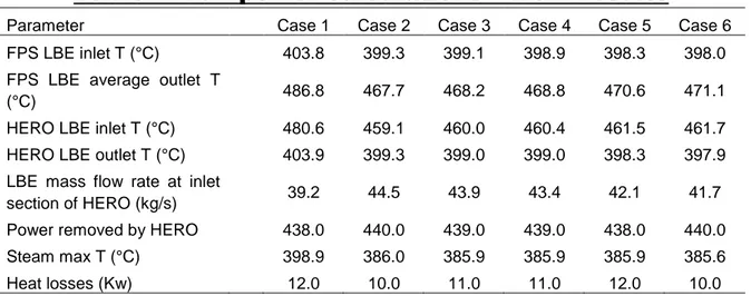
The mono-dimensional model includes each component of the test section: the feeding conduit, the fuel pin simulator, the release pipe, the fitting volume, the riser, the separator and the HERO test section (primary and secondary side). The FPS is analyzed sub-channel by sub-channel modelling the HS with 72 parallel pipes, divided into 15 control volumes linked with 1536 cross junctions, which simulates each sub-channel (see Figure 11). The thermal power supplied by the 37 pins is reproduced with 5760 heat structure nodes and other 1728 thermal nodes model the heat dispersion through the hexagonal wrapper. The nodalization scheme of the FPS has been obtained in order to compare the LBE temperature in the exact position of the thermocouples (TCs) installed inside the HS. For the evaluation of the heat transfer coefficient (HTC) in a rod bundle geometry for liquid metals, the Todreas & Kazimi correlation is implemented in R5-3D [7]:
𝑁𝑢 = 4.0 + 0.33 (𝑝 𝑑) 3.8 (𝑃𝑒 100) 0.86 + 0.16 (𝑝 𝑑) 5
Developed in the range of 1.1<p/d<1.4 and 10<Pe<5000. Previous activities on HLM technologies, highlighted the underestimation of the HTC using this correlation and a better estimation with Ushakov correlation [8]:
𝑁𝑢 =
7.55𝑝 𝑑− 20(
𝑝 𝑑)
−13 + 3.67(
90𝑝𝑑)
2 𝑃𝑒(0.56+0.19𝑝𝑑)In order to better reproduce the HTC, an artificial fouling factor of 1.31 is evaluated as the ratio between Ushakov correlation (p/d = 1.8, the real value) and Todreas & Kazimi correlation (p/d = 1.4), in the range of the HS temperatures and asuming the nominal flow conditions. The heat transfer correlation used for the non-bundles geometry is the Seban-Shimazaki [7]:
𝑁𝑢 = 5.0 + 0.025𝑃𝑒0.8
Upstream the FPS, the pressure drop of the Venturi nozzle is simulated with a concentrated pressure loss coefficient K, dependent on the flow conditions and validated with post-test analysis conducted on CIRCE-ICE campaign [5] [6].
The argon injection at the inlet section of the riser is simulated with boundary conditions: the time dependent volume sets gas inlet conditions and the time dependent junction, linked with the second volume of the riser, adjusts the mass flow rate injection. An additional time dependent volume sets the pressure of the gas plenum of the facility.
The SG primary side is simulated with a single equivalent pipe composed of 43 volumes and hydraulically coupled with the separator at the top and with the 3D component at the bottom. The secondary side of the SGBTs is collapsed in two equivalent pipe: the first one for the descending side and the second one for the ascending side. The feed-water inlet conditions are set with the time dependent volume, connected to the descending pipe with the time dependent junction which sets the inlet mass flow rate. Another time dependent volume is connected with the upper zone of the ascending pipe to fix the steam pressure at the steam chamber. The components which simulates the HERO SGBT are thermally coupled with 4 heat structures; in particular, as the case of the FPS, the heat structure which couples the LBE and the steam side, is adjusted with a calibrated fouling factor, calculated as the ratio between Ushakov correlation (p/d = 1.42) and Todreas & Kazimi correlation (p/d = 1.4), to better reproduce the HTC.
The pressure losses due to the grids installed into the FPS and the steam generator are calculated by the Rheme correlation [5]: 2 2
0.5
grid vp
C
v
where ρ and v are respectively the density and the velocity of the fluid while ε represents the blockage factor of the grids, calculated as:
grid
flow
A
A
Title: Pre-tests analyses of CIRCE/HERO
experimental campaign using system codes
Project:
ADP ENEA-MSE PAR 2016Distribution
P
UBLICIssue Date
01.12.2017
Pag.
R
ICERCAS
ISTEMAE
LETTRICORef.
ADPFISS-LP2-151Rev. 0
14 di 35
10 0.264 2.79 273.14
2.79 10
2.6
3.5
,
Re
Re
vC
MIN
The mono-dimensional scheme are hydraulically coupled with multi-dimensional component by three junctions and both the models are consistent with the vertical sliced approach. The MULTID component is composed of 51 axial levels, 4 radial meshes and 8 azimuthal intervals and it is obtained in order to compare the LBE temperature in the exact positions of the TCs installed into the main pool. The number of azimuthal and radial meshes is chosen on the basis of the geometrical position of the internal components and the porosity factors are used to reproduce the volume occupied by the internals.
In Table 2 the dimensions of the global model are summarized.
Title: Pre-tests analyses of CIRCE/HERO
experimental campaign using system codes
Project:
ADP ENEA-MSE PAR 2016Distribution
P
UBLICIssue Date
01.12.2017
Pag.
R
ICERCAS
ISTEMAE
LETTRICORef.
ADPFISS-LP2-151Rev. 0
16 di 35
Figure 11: FPS nodalizzation scheme
Table 2: Model dimensions
Parameter Value
Number of hydrodynamic volumes 2942
Number of hydrodynamic junctions 7565
Number of heat structure mesh points 21153
4 Pre-Test Calculations
4.1 Identification of full power steady state conditions
The experiment consists of the transition from forced to natural circulation in a loss of flow accidental scenario. Every simulations, in this work, are carried out using the most recent thermophysical properties correlations, recommended by NEA [9] and implemented in RELAP5-3D© in the activity described in [10]. In order to identify the initial conditions of the transient tests, the following cases are analyzed:
Case 1: to achieve a constant temperature drop across the FPS equal to 80°C in the range of about 400-480°C, representative of the temperature drop across the ALFRED core. The thermal power supplied by the FPS is set to the nominal value of 450 kW, the pool is initialized with the average temperature of 396°C and the argon and the feedwater mass flow rate are respectively 1.29 Nl/s and 0.3308 kg/s;
Case 2: to achieve the LBE mass flow rate across the SG equal to 44.7 kg/s, representative of the scaled down SG of ALFRED. The boundary conditions are the same of case 1, except the argon injection, set to 2.354 Nl/s;
Cases from 3 to 6 have the same boundary conditions of case 1, except gas flow rate, respectively 2.242, 2.13, 1.85 and 1.79 Nl/s.
The boundary conditions of each cases are summarized in Table 3 and the main results, after 8 hours of problem time, are shown in Table 4. The full power steady state conditions, identified as the initial conditions for the transient simulations, is the case 1. The Figure 12 shows the LBE mass flow rate at the inlet section of the SG. The calculation starts in stable conditions; at 50 s the Ar is injected and the LBE mass flow rate immediately assumes the value of 36.5 kg/s. After 220 s from the beginning of the simulation, the HS starts to supply the thermal power up to the nominal value at 390 s, and the mass flow of the primary coolant increases to the value of 38 kg/s. The temperature of the global system starts to increase and at 2000 s the feed-water is injected in the bayonet tubes and the LBE mass flow rate reaches the nominal value of 39.2 kg/s. The Figure 13 depicts the LBE temperature at the inlet and outlet section of the FPS and the SG. After
the activation of the FPS, the temperature at the outlet section of the FPS starts to increase and the heat dissipation through the pool causes a ΔT between the external and the internal subchannels of about 20°C (see green and red line). The temperature at the inlet section of the SG increases following the FPS temperature and, due to the absence of the secondary alimentation, there is not a decrease of temperature along HERO. When the feed-water is injected in the unit, the steam generator start to removed thermal power and the LBE SG outlet temperature rapidly decreases to the value of 418°C and, with a delay time of about 450 s, the temperature at the FPS and at the inlet section of HERO reaches the maximum value; then the average temperature of the primary flow path decreases to the nominal values summarized in Table 4. The Figure 13 shows that the LBE enters the HS with a uniform temperature and it is confirmed in Figure 14, which depicts the temperature distribution in different section of the fuel pin simulator, highlighting the effects of the heat dissipation through the hexagonal wrap. The Figure 15 is a representation of the LBE in the most representative section, signed in red in Figure 16 where the FPS is depicted in yellow and the SG in orange. The Figure 15 highlights the temperature difference between the internal components and the LBE inside the pool and shows that a thermal stratification phenomenon occur at about 2.8 m from the bottom of the vessel. The level of the thermal stratification seems to be influenced by the heat dissipation from the internal components, occurring at the same level of the hottest zone of the HS.
Table 3: Full power calculations – boundary conditions
Parameter Case 1 Case 2 Case 3 Case 4 Case 5 Case 6
FPS thermal power (kW) 450.0 450.0 450.0 450.0 450.0 450.0 LBE average T inside the
pool (°C) 396.0 396.0 396.0 396.0 396.0 396.0
Ar mass flow rate (Nl/s) 1.290 2.354 2.242 2.130 1.850 1.790
Steam pressure (bar) 172.0 172.0 172.0 172.0 172.0 172.0
FW inlet T (°C) 335.0 335.0 335.0 335.0 335.0 335.0
FW mass flow rate (kg/s) 0.331 0.331 0.331 0.331 0.331 0.331
Table 4: Full power calculations – main results
Parameter Case 1 Case 2 Case 3 Case 4 Case 5 Case 6
FPS LBE inlet T (°C) 403.8 399.3 399.1 398.9 398.3 398.0
FPS LBE average outlet T
(°C) 486.8 467.7 468.2 468.8 470.6 471.1
HERO LBE inlet T (°C) 480.6 459.1 460.0 460.4 461.5 461.7 HERO LBE outlet T (°C) 403.9 399.3 399.0 399.0 398.3 397.9 LBE mass flow rate at inlet
section of HERO (kg/s) 39.2 44.5 43.9 43.4 42.1 41.7
Power removed by HERO 438.0 440.0 439.0 439.0 438.0 440.0
Steam max T (°C) 398.9 386.0 385.9 385.9 385.9 385.6
Title: Pre-tests analyses of CIRCE/HERO
experimental campaign using system codes
Project:
ADP ENEA-MSE PAR 2016Distribution
P
UBLICIssue Date
01.12.2017
Pag.
R
ICERCAS
ISTEMAE
LETTRICORef.
ADPFISS-LP2-151Rev. 0
18 di 35
Figure 12: LBE mass flow rate
Title: Pre-tests analyses of CIRCE/HERO
experimental campaign using system codes
Project:
ADP ENEA-MSE PAR 2016Distribution
P
UBLICIssue Date
01.12.2017
Pag.
R
ICERCAS
ISTEMAE
LETTRICORef.
ADPFISS-LP2-151Rev. 0
20 di 35
Figure 16: representative section
4.2 Transient analysis
The starting point for the transient analysis is considered the case 1. Three transient tests are considered in order to individuate the reference accidental scenario:
Transient Test 1: it consists of a protected loss of LBE pump, decreasing to 0 the argon injection with a curve simulating the presence of a pump flywheel. The FPS power simulates a decay heat curve, scaled down by a typical curve for fast reactor and compensated with heat losses through the main vessel, and feedwater mass flow rate decreases to 10% of the nominal value to simulate the activation of the DHR system;
Transient Test 2: the boundary conditions are the same of the Transient Test 1, except the feed-water mass flow rate, set to 20% of the nominal value;
Transient Test 3: it consists of a loss of LBE pump plus loss of DHR function in hot conditions; the boundary conditions are the same of the Transient Test 1, except the feed-water mass flow rate which is disactivated.
The problem time of each Transient Test is 1000 s; Table 5 and Table 6 summarized the boundary conditions of the transient simulations.
Table 5: FW and Ar injection
Time (s) Feed-water flow (kg/s) Ar injection (kg/s)
0 0.3307850 (TrT 1) 0.002310
1 0.1819310 (TrT 1) 0.002081
Title: Pre-tests analyses of CIRCE/HERO
experimental campaign using system codes
Project:
ADP ENEA-MSE PAR 2016Distribution
P
UBLICIssue Date
01.12.2017
Pag.
R
ICERCAS
ISTEMAE
LETTRICORef.
ADPFISS-LP2-151Rev. 0
22 di 35
4 0.0330785 (TrT 1) 0.001650 5 0.0330785 (TrT 1) 0.001540 10 0.0330785 (TrT 1) 0.001155 20 0.0330785 (TrT 1) 0.000770 30 0.0330785 (TrT 1) 0.000578 50 0.0330785 (TrT 1) 0.000385 100 0.0330785 (TrT 1) 0.000210 150 0.0330785 (TrT 1) 0.000110 200 0.0330785 (TrT 1) 0.000045 300 0.0330785 (TrT 1) 0.000000 1000 0.0330785 (TrT 1) 0.000000Table 6: Compensated power curve
Time (s) Power shut-down curve (W) Compensated FPS power (W) 0 450000 450000 1 97190 107190 2 83682 93682 3.5 71273 81273 5 62713 72713 7.5 53132 63132 10 46928 56928 15 38839 48839 22.5 31771 41771 30 27373 37373 40 23210 33210 50 20148 30148 60 17949 27949 90 14179 24179 120 12137 22137 180 9938 19938 240 8917 18917 300 8368 18368 360 7818 17818 420 7425 17425 480 7190 17190 540 6954 16954 600 6718 16718 660 6483 16483 720 6247 16247 780 6169 16169 840 5933 15933 900 5776 15776 1000 5776 15776
4.2.1 Transient Test 1
The main events of the transient test are summarized in Table 7. Figure 17 and Figure 18 depicts the evolution of the LBE mass flow rate at the inlet section of the SG and LBE inlet and outlet temperatures of the FPS and HERO. Immediately after the beginning of the transient test, the temperature at the outlet section of the FPS decreases to the minimum value of 420°C; at this time, the thermal power has nearly reached the value of the compensated decay power and the LBE mass flow rate is close to 50% of the nominal value. This causes the minimum value of the temperature drop across the FPS (at 80 s) and, after a delay time of about 30 s, also the minimum value of the temperature drop across the SG, when the LBE outlet temperature reaches the value of 440°C. The LBE mass flow rate continues to decrease reaching the minimum value of 1.4 kg/s after 340 s from the beginning of the test. At this time, the FPS outlet temperature reaches the peak value of 470 °C, remaining lower than the nominal value of 497°C and the outlet temperature of the SG reaches the minimum value of about 360 °C, lower than the temperature inside the main vessel (see also Figure 20 (c)). Then the LBE mass flow rate reaches the value of about 3.7 kg/s and the average temperature of the global system decreases to the final value. The Figure 20 shows the evolution of the temperature inside the main vessel and it highlights that, during the transient test, at the thermal stratification level, the gradient of the temperature versus the elevation is less than the steady state conditions, as shown also in Figure 19 which depicts the vertical trend of the temperature inside the pool. This is due to the hot LBE exiting from the SG during the transient test. The Figure 21 summarized the evolution of the LBE temperature inside the FPS, previously described.
Table 7: TrT 1 – Main events
Time (s) Main event
0 Start of the transient sequence
80 Minimum value of the LBE temperature at the outlet section of the FPS 110 Peak temperature at SG outlet section
340 Minimum value of the LBE mass flow rate
350 Peak temperature at the outlet section of the FPS and minimum temperature at the outlet of HERO
Title: Pre-tests analyses of CIRCE/HERO
experimental campaign using system codes
Project:
ADP ENEA-MSE PAR 2016Distribution
P
UBLICIssue Date
01.12.2017
Pag.
R
ICERCAS
ISTEMAE
LETTRICORef.
ADPFISS-LP2-151Rev. 0
24 di 35
Title: Pre-tests analyses of CIRCE/HERO
experimental campaign using system codes
Project:
ADP ENEA-MSE PAR 2016Distribution
P
UBLICIssue Date
01.12.2017
Pag.
R
ICERCAS
ISTEMAE
LETTRICORef.
ADPFISS-LP2-151Rev. 0
26 di 35
Title: Pre-tests analyses of CIRCE/HERO
experimental campaign using system codes
Project:
ADP ENEA-MSE PAR 2016Distribution
P
UBLICIssue Date
01.12.2017
Pag.
R
ICERCAS
ISTEMAE
LETTRICORef.
ADPFISS-LP2-151Rev. 0
28 di 35
(a) 0 s (b) 80 s (c) 350 s (d) 1000 sFigure 21: TrT1 – FPS temperature evolution
4.2.2 Comparison of the transient tests
The following analysis is a comparison of the transient tests. The Figure 22 shows the comparison of the LBE mass flow rate at the inlet section
n of HERO; the primary flow assumes the same value during the decrease but, after about 145 s, the driving force is influenced by the thermal power removed by the SG and the LBE mass flow of the test 2 is constantly greater than test 1 and 3. In particular, during the transient 3, the driving force only depends on the heat losses through the main vessel, since the feed-water injection is stopped. Between 225 and 370 s, the LBE reverse flow occurs and it causes the particular trend of the temperature inside the test section, shown in Figure 23 and Figure 24. The Figure 23 depicts the LBE temperature at the inlet and outlet section
of the HS; the transient 2 follows the same qualitative trend of the test 1, assuming lower temperatures in comparison with the reference transient. Significant differences occur during the test 3, when the LBE mass flow assumes negative values; during the first 220 s, the transient test 3 assumes the same temperature trend of test 1 and 2 but after this time the inlet temperature of the HS reaches the pick value of 455°C and the same effect occurs at the outlet section of the SG, where the LBE temperatures reaches the minimum value of 353°C (see Figure 24). After that, the LBE reaches the nominal value of 0.5 kg/s and the temperature of the test section moves to the final values; in particular, at the outlet section of the FPS, the maximum value of 546°C is reached at the end of the transient test. The temperature trend at the end of the tests are compared in Figure 25 and the LBE temperature evolution inside the main vessel and on different section of the HS for the transient test 3 are depicted in Figure 26 and Figure 27.
Title: Pre-tests analyses of CIRCE/HERO
experimental campaign using system codes
Project:
ADP ENEA-MSE PAR 2016Distribution
P
UBLICIssue Date
01.12.2017
Pag.
R
ICERCAS
ISTEMAE
LETTRICORef.
ADPFISS-LP2-151Rev. 0
30 di 35
Figure 23: Comparison – FPS temperatures
Title: Pre-tests analyses of CIRCE/HERO
experimental campaign using system codes
Project:
ADP ENEA-MSE PAR 2016Distribution
P
UBLICIssue Date
01.12.2017
Pag.
R
ICERCAS
ISTEMAE
LETTRICORef.
ADPFISS-LP2-151Rev. 0
32 di 35
(a) 0 s (b) 110 s (c) 360 s (d) 1000 s(a) 0 s (b) 80 s
(c) 360 s (d) 1000 s
Figure 27: TrT 3 – FPS temperature evolution
5 Conclusions
The scope of this work is to present the pre-test analyses on CIRCE-HERO test facility and to identify the test matrix for the experimental campaign with a detailed model with the use of multidimensional component for the pool. The simulations have been performed with Relap5-3D© code, upgrading the validated model of CIRCE-ICE facility and using the most recent thermo-physical properties correlations of the LBE, recommended by NEA and implemented in R5-3D during a previous activities. The analysis aims to investigate the transition from forced to natural circulation in a protected loss of flow accident scenario. At first step, a sensitivity analysis has been performed in order to identify the steady state conditions which represents the initial conditions for the transient tests. After that, three transient calculations have been carried out, reducing the feedwater mass flow rate from 20% to 0% of the nominal value. The simulation
Title: Pre-tests analyses of CIRCE/HERO
experimental campaign using system codes
Project:
ADP ENEA-MSE PAR 2016Distribution
P
UBLICIssue Date
01.12.2017
Pag.
R
ICERCAS
ISTEMAE
LETTRICORef.
ADPFISS-LP2-151Rev. 0
34 di 35
but with a sufficient secondary mass flow rate (about 10%), the FPS coolability is guaranteed also in short term, without an excessive outlet temperature increment. When feedwater mass flow rate is set to zero, a reverse flow of the primary coolant is predicted by the code with an acceptable increment of FPS outlet temperature: this phenomenon will be eventually checked and investigated trough the experimental campaign.The transient test 1 has been identified as the reference scenario.
6 Acronyms and definitions
Acronym Definition
ALFRED Advanced Lead Fast Reactor European Demonstrator CIRCE CIRColazione Eutettico
FPS Fuel Pin Simulator
FW Feed-water
HERO Heavy liquid mEtal pRessurized water cOoled tubes HLM Heavy Liquid Metal
HS Heat Source
HTC Heat Transfer Coefficient
HX Heat eXchanger
ICE Integral Circulation Experiment LBE Lead-Bismuth Eutectic
LEADER Lead-cooled European Advanced DEmonstartion Reactor NPP Nuclear Power Plant
R5 Relap5
SG Steam Generator
SGBT Steam Generator Bayonet Tube
REFERENCES
[1] V. Narcisi, F. Giannetti, G. Caruso, D. Rozzia, A. Del Nevo, M. Tarantino, Installazione della sezione di prova HERO nella facility CIRCE: sviluppo nedalizzazione e progettazione della campagna sperimentale, Report ENEA ADPFISS – LP2 – 133.
[2] V. Narcisi, F. Giannetti, M. Tarantino, A. Del Nevo, G. Caruso, Pre-test analysis of protected loss of primary pump transients in CIRCE-HERO facility, Journal of Physics: Conference series, doi: 10.1088/1742-6596/923/1/012005, 2017.
[3] V. Narcisi, D. V. Di Maio, F. Giannetti, G. Caruso, D. Rozzia, A. Del Nevo, M. Taratino, ALFRED-SGBT. Preliminary characterization by the HERO test section, Report ENEA
[4] Team T R C D 1995 RELAP5-3D© Code Manual Vol. 1 Code Structure, System Models and Solution Methods NUREG/CR55.
[5] V. Narcisi, F. Giannetti, M. Tarantino, D. Martelli, G. Caruso, Pool temperature stratification analysis in CIRCE-ICE facility with RELAP5-3D© model and comparison with experimental tests, Journal of Physics: Conference series, doi: 10.1088/1742-6596/923/1/012006, 2017.
[6] V. Narcisi, F. Giannetti, P. Lorusso, M. Tarantino, A. Del Nevo, G. Caruso, Thermal Stratification analysis in CIRCE-ICE pool facility with RELAP5-3D© model, Global Symposium on Lead and Lead Alloy based Nuclear Energy Science and Technology GLANST-2017.
[7] Team T R C D 1995 RELAP5-3D© Code Manual Vol. 4 Models and Correlations NUREG/CR55. [8] F. Giannetti, D. V. Di Maio, A. Naviglio, G. Caruso, Thermal-hydraulic analysis of an innovative
decay heat removal system for lead-cooled fast reactors, Nuclear Engineering and Design, 305 168-178, 2016.
[9] NEA 2015, Handbook on Lead-bismuth Eutectic Alloy and Lead Properties, Materials Compatibility, Thermal-hydraulics and Technologies, 647-730.
[10] P. Balestra, F. Giannetti, G. Caruso, A. Alfonsi, New RELAP5-3D Lead and LBE Thermophysical Properties Implementation for Safety Analysis of Gen IV Reactors, 2016, 2016.