Dipartimento di Meccanica
Scuola di Dottorato “Pitagora” in Scienze Ingegneristiche
Dottorato di Ricerca in Ingegneria Meccanica XXI Ciclo
SETTORE SCIENTIFICO DISCIPLINARE: ING-IND/16
Tesi di Dottorato
Fundamental Aspects
in Metal Cutting Modelling
Coordinatore
Supervisore
Prof. Sergio Rizzuti
Prof. Luigino Filice
Candidata
Ing. Stefania Rizzuti
Dissertazione finale sottomessa per ottenere il titolo di Dottore di Ricerca in Ingegneria Meccanica Anno Accademico 2007/2008
C
ONTENTS
I
NTRODUCTION 1C
HAPTER1.
F
INITEE
LEMENTS
IMULATION OFM
ETALC
UTTING1.1 I
NTRODUCTION 31.2 M
ODELLING OFC
UTTINGP
ROCESSES 51.3 C
RITICALA
SPECTS OF THEN
UMERICALS
IMULATION 101.3.1 FRICTION AT THE TOOL –CHIP INTERFACE 12
1.3.2 THERMAL ASPECTS 12
1.3.3 MATERIAL FLOW STRESS AT HIGH STRAIN RATE AND TEMPERATURE 14
C
HAPTER2.
F
RICTIONM
ODELLING2.1 I
NTRODUCTION 162.2 F
RICTIONM
ODELS FORM
ACHINING17
2.3 E
XPERIMENTS ANDN
UMERICALP
REDICTIONS 192.3.1 CONSTANT SHEAR FRICTION ON THE WHOLE TOOL-CHIP INTERFACE 21 2.3.2 CONSTANT COULOMB FRICTION ON THE WHOLE TOOL-CHIP INTERFACE 23 2.3.3 CONSTANT SHEAR FRICTION IN STICKING REGION AND COULOMB FRICTION IN
SLIDING REGION 23
2.3.4 STICKING-SLIDING MODEL 24
2.3.5 VARIABLE SHEAR FRICTION ON THE TOOL-CHIP INTERFACE 25
2.3.6 BEST RESULTS FOR EACH PROPOSED MODEL 25
2.3.7 ON THE TEMPERATURE IN THE TOOL 26
2.4 D
IFFERENTC
OUPLEST
OOL-
W
ORKPIECE 282.4.1 TEMPERATURE ESTIMATION 31
2.5 D
EPENDENCE OFM
ACHININGS
IMULATIONE
FFECTIVENESS ONM
ATERIAL2.5.1 EXPERIMENTAL TESTS AND NUMERICAL SIMULATIONS 34
2.5.2 MATERIAL AND FRICTION MODELLING 36
2.5.3 NUMERICAL RESULTS 39
2.5.3.1 FORCE PREDICTIONS USING THE CONSTANT SHEAR MODEL 39 2.5.3.2 FORCE PREDICTIONS USING THE COULOMB MODEL 40 2.5.3.3 FORCE PREDICTIONS USING THE STICKING-SLIDING MODEL 41 2.5.3.4 CUTTING CONTACT LENGTH AND SHEAR ANGLE PREDICTIONS USING THE CONSTANT SHEAR
MODEL 43
2.5.3.5 CUTTING CONTACT LENGTH AND SHEAR ANGLE PREDICTIONS USING THE COULOMB MODEL 46 2.5.3.6 CUTTING CONTACT LENGTH AND SHEAR ANGLE PREDICTIONS USING THE STICKING-SLIDING
MODEL 47
2.5.4 RESULTS DISCUSSION 49
2.6 C
ONCLUSIONS 52C
HAPTER3.
A
N
EWA
PPROACH TOM
ODELH
EATT
RANSFERP
HENOMENA AT THET
OOL–
C
HIPI
NTERFACE3.1 I
NTRODUCTION 543.2 T
HE ROLE OF THE GLOBAL HEAT TRANSFER COEFFICIENT 553.3 E
XPERIMENTAL PROCEDURE 583.4 P
ROCEDURE TO CALCULATE THE GLOBAL HEAT TRANSFER COEFFICIENT 593.5 R
ESULTSA
NALYSIS 613.6 C
ASE STUDY:
3D
F
INITEE
LEMENTA
NALYSIS OFT
OOLW
EAR 643.6.1 THE PROPOSED TOO WEAR MODEL 65
3.6.2 3DEXPERIMENTAL TESTS 69
3.6.3 3DNUMERICAL MODELLING 70
3.6.4 RESULTS AND DISCUSSION 72
3.7 C
ONCLUSIONS 74C
HAPTER4.
D
EFINITION OFM
ATERIALM
ODELS THROUGHM
ACHININGT
ESTS4.1 I
NTRODUCTION 764.3 T
HEP
ROPOSEDP
ROCEDURE 82 4.3.1 EXPERIMENTAL TESTS 83 4.3.2 NUMERICAL PROCEDURE 844.4 S
OMEC
ONSIDERATIONS 874.5 C
ONCLUSIONS 87C
ONCLUSIONS 88R
EFERENCES 90A
CKNOWLEDGMENTS 101I
NTRODUCTION
Machining is one of the most common manufacturing processes. Nearly every mechanical component in use has undergone a machining operation at some stage of its manufacturing process. Therefore, the effectiveness of metal cutting process significantly affects the overall cost of final products, and there is a strong drive to reduce time and cost of machining operations.
In the past century, a great deal of research has been devoted toward understanding the mechanics of metal cutting, with the objective of obtaining more effective cutting tools and more efficient manufacturing process plans. Traditionally, these objectives have been achieved by experimentation and prototyping. In spite of extensive research in this field, the basic mechanics of the cutting process and the interaction of many factors which leads to its great variety is not yet totally understood.
Understanding of cutting mechanics has caught the attention of many researchers, and many analytical, empirical and numerical models have been contributed to the knowledge in this field. While all these models have advanced the common knowledge about the cutting process, the suitability of a cutting model depends on prediction of machining performance in order to facilitate effective planning of machining operations achieving optimal productivity, quality and cost. In particular, numerical modelling of this process has attracted the attention of many researchers in recent years, because of the better insight it can provide into the mechanics of chip formation by avoiding many of the simplifications needed in other approaches. However, the reliability of a numerical cutting model is dependent on two factors; the reliability of the input data in terms
of material and frictional characteristics, and the correctness and efficiency of the numerical approach, formulation and procedures used.
This dissertation deals with some fundamental aspects of the numerical simulation of the cutting process, which constitute, up to now, a big challenge for the researchers involved in this field. The aim is to supply a useful scientific contribution to the ever-increasing need of reliable, robust and ready-to-use simulation tools. In particular, the achieved specific objectives of the proposed research are:
• analysis of the role played by the friction models within the numerical simulation of orthogonal cutting. The investigation deal with the prediction of both mechanical and thermal variables;
• development of a physically-consistent model for the global heat transfer coefficient, by means of an inverse approach based on a set of experimental data and on a mixed updated Lagrangian - Eulerian approach. The model was validated through its direct implementation in the FE code and its application in tool wear prediction;
• development of a numerical strategy for the identification of a simplified material law to properly define the behaviour of the workpiece material, utilizing only machining tests and taking also into account the thermal phenomena involved in the process.
This research has been performed at the Department of Mechanical Engineering of the University of Calabria and during research visit at the “Laboratoire de Mécanique des Systèmes et des Procédés (LMSP), at ENSAM (Ecole Nationale Supérieure d’Arts et Métiers), Paris, directed by Prof. F. Chinesta.
The results of the PhD activity were also possible thanks to the significant collaboration with other Italian research centres, namely the Department of Mechanical Technology, Production and Management Engineering, University of Palermo, the Department of Production Systems and Economics, Polytechnic of Torino and Institute of Science and Technology of Ceramics, CNR-Torino, and the
C
HAPTER
1
F
INITE
E
LEMENT
S
IMULATION OF
M
ETAL
C
UTTING
1.1 I
NTRODUCTION
It is recognized that machining operations play a leading role in manufacturing. A study carried out in 1998 by Merchant [1] showed that about 15% of the value of all the mechanical components manufactured worldwide is achieved through machining. Probably this quota increased in the last decade due to the increase of machining market and the demands of the manufacturing industries for micro and nano-machining [2]. As a consequence of its large economic and technical importance, a great number of researches have been carried out in order to optimize machining process in terms of improved quality, increased productivity and reduced cost [2].
A research conducted by Armarego et al. [3], in the USA in 1996, revealed the following important factors: the cutting tool was properly selected less than in 50% of the cases, the tool was used at the rated cutting speed only in the 58% of the cases, and finally only 38% of the tools were used up to their full tool-life capability. Since then many efforts have been done in this direction, but the situation still urges the need for developing more scientific approaches in order to improve machining performance.
Moreover, accurate predictions of the results of the machining operations are required. This approach relies strongly on the prediction of the accuracy of shape and dimensions, and the surface finish and properties of the subsurface layer of the parts produced, the machining times required and the costs of the operation performed. In general, existing methods for the control of manufacturing operations, mainly based on the experience and craftsmanship of the manufacturing engineers/machinists, are becoming obsolete and have to be replaced by science-/knowledge- based methods. These are the main reasons for the development and introduction of CAD/CAM/CAPP systems to support process planning and control in flexible manufacturing/machining systems capable of performing a large variety of machining operations [4].
It is expected that future production will unquestionably require rapid and reliable adaptation to technological innovations, and these will be essential for a continued existence in the marketplace. Consequently, much more effort must be made to consider available process knowledge in order to improve component properties, and process parameters have to be based on product-related production requirements [5]. One way of meeting these numerous requirements is to use modelling, with the following purposes [6]:
- To find ways of optimizing process quickly and realistically. - To permit realistic predictions of process results.
- To obtain new knowledge of process steps and process design. - To derive capabilities of process monitoring and control from this.
For the past 50 years metal cutting researchers have developed many modelling techniques including analytical techniques, slip-line solutions, empirical approaches, and finite element techniques.
In particular, several enhancements have been obtained in the last decade thank to the use of Finite Element simulation, which was used by numerous researchers to predict some typical machining variables, such as cutting forces, chip morphology, surface integrity, etc. [7].
1.2 M
ODELLING OF
C
UTTING
P
ROCESSES
Metal cutting is a highly non-linear and coupled thermo-mechanical process, where the mechanical work is converted into heat through the plastic deformation involved during chip formation and also due to frictional work between the tool, chip and workpiece.
A thorough understanding of the material removal process in metal cutting is essential in selecting the tool material and in design, and also in assuring consistent dimensional accuracy and surface integrity of the finished product.
The earliest analytical models explaining the mechanical of metal cutting were proposed by Merchant [8,9], Piispanen [10], and Lee and Shaffer [11]. These models are known as shear angle models; they relate the chip shear angle to the tool rake angle. Kudo [12] introduced curved shearing to account for the controlled contact between the curved chip and the straight tool face. These models assumed rigid-perfectly plastic material behaviour.
Analytical models including the effect of work hardening and strain-rate effects were proposed by Palmer and Oxley [13] and Oxley et al. [14]. Interfacial friction along the toll-chip interface was incorporated into these viscoplastic models by Doyle et al. [15]. The effect of heating in metal cutting was included in an analytical model by Trigger and Chao [16]. Three-dimensional geometric conditions in metal cutting were considered by Usui et al. [17] using an energy approach.
In recent years, the finite element method has become the main tool for simulating metal cutting processes.
An important aspect of finite element simulation of metal cutting is the type of numerical formulation used, because of the great implications it has in the success of such analyses.
Typical approaches for numerical modelling of metal cutting process are Lagrangian and Eulerian techniques, as well as a combination of both called the
arbitrary Lagrangian-Eulerian formulation (denoted in the literature by the acronym ALE) [18,19].
In Lagrangian approach, the mesh follows the material, it is “attached to the workpiece”. In the updated Lagrangian formulation, because the elements move with the workpiece, they experience both large plastic deformation and rigid body motion. Under such circumstances, the larger deformation, and the changing material properties due to stress and strain in the material, need to be considered. The advantage of the updated Lagrangian formulation is that the tool can be simulated from the start of the cutting to a steady state. [20] But in order to extend the cutting time until steady state, the model requires large computational times. In addition, in order to perform chip separation, material failure and separation criteria are necessary. An other problem in the Lagrangian formulation is the computational instability due to the large distortion of some elements. This problem may eventually cause unrealistic results or premature termination of the analysis. Severe element distortion also results in a degradation of the accuracy. To address this issue it is useful to redefine the mesh system periodically, and so algorithms of remeshing and rezoning have to be included in the finite element codes.
The first model for orthogonal cutting utilizing simulated chip formation from the incipient stage to the steady state was due to Strenkowski and Carroll [21]. In their study, no heat was assumed to be conducted between chip and workpiece. The values of the chip separation criterion based on effective plastic strain were used to simulate the cutting process, without comparison to experiments. When it exceeded a specified value at the nodes closest to the tool tip, the nodes would be separated to form the machined surface and chip underneath. They found that different values selected for chip separation criterion based on the effective plastic strain affect the magnitude of the residual stresses in the machined surface of the workpiece. Strenkowski and Mitchum [22] presented the modified cutting model. They analyzed the transition from indentation to incipient cutting and used their results to evaluate the values for the chip separation criterion. Their results
showed that the criterion value, based on the effective plastic strain, increases with depth of cut.
Lin and Lin [23] developed a thermo-elastic-plastic cutting model. The finite difference method was adopted to determine the temperature distribution within the chip and the tool. In their model, a chip separation criterion based on the strain energy density was introduced. They verified that the chip separation criterion value based on the strain energy density was a material constant and was independent of uncut chip thickness. With this cutting model, Lin and Pan [24,25] simulated an entire orthogonal cutting process with tool frank wear from incipient stage to the steady state. The agreement between simulation and experimental results for cutting forces, friction force, the chip thickness, and contact length was found to be acceptable. Lin and Liu [26] analyzed an orthogonal finish machining using tungsten carbide and diamond tools that had different coefficients of thermal conductivity. Comparing the cutting forces predicted by the model with those obtained by experiment for orthogonal finish machining, they showed that the model could simulate the orthogonal finish machining process for different tool materials.
Ueda and Manabe [27] simulated the oblique cutting process as the first step in the three dimensional deformation analysis of cutting. With a displacement-based criterion, the chip formation process is continuously simulated from the beginning of the cutting until the steady state. When the distance between the tool tip and the nodal point located immediately in front exceeded a predefined critical value of separation, the nearest element was separated. However, the physics of a displacement-based chip separation criterion has not been clearly characterized. The results of the rigid plastic finite element analysis are qualitatively compared with in situ scanning electron microscope observation of the cutting experiments.
Zhang and Bagchi [28] developed conditional link elements handling chip separation from the workpiece. A displacement-based chip separation criterion was used to selectively null the link elements as the tool progressed. The validity of this model was examined by comparing the calculated cutting force, feed force,
shear angle, and plastic deformation with those from experiments. But because this model ignored the temperature and strain rate effects, it was only useful for low-speed machining.
Hashemi et al. [29] presented the first cutting model that did not assume a predefined cutting path. A unique chip fracture algorithm was implemented to permit tool travel between any set of nodes and t allow segmentation of the chip. Although a number of important features such as friction, temperature effects, and workpiece strain hardening were neglected and an overly coarse mesh that restricted the number of potential tool pathways was used, this model was thought to be a considerable achievement.
In Eulerian approach, the mesh is fixed spatially and the material flows through the mesh. Eulerian approach is suitable to analyse the steady state of cutting process, not including the transition from initial to steady state cutting process. Cutting process analysis with Eulerian approach requires less calculation time because the workpiece model consists of fewer elements. That is the reason why before 1995 the applications of Eulerian approach in chip formation analysis overrun those of Lagrangian approach. But experimental work is often necessary in order to determine the chip geometry and shear angle, which is an unavoidable part of geometry modelling.
The first application of the approach to metal cutting using a viscoplastic material model was reported by Strenkowski and Carroll [30]. This model is the so-called Eulerian cutting model. As this approach considers each element to be a fixed control volume, such that the mesh does not move with the flowing material as with the Lagrangian approach, the boundaries of the chip must be known in advance. These researchers later investigated the correlation between the Lagrangian and Eulerian frames. Both approaches showed reasonably good correlation with experimental results for cutting forces, residual stresses and strains, and chip geometry. With the Eulerian approach, Strenkowski and Moon [31] analyzed steady-state orthogonal cutting with the capability to predict chip geometry and chip-tool contact length for purely viscoplastic materials.
In 1991, Komvopoulos and Erpenbeck [32] investigated steady-state cutting effects of cratered tools with built-up edges. They examined the effects of material constitutive behaviour for rate-independent elastic-perfectly-plastic materials and rate-sensitive elastic-plastic isotropically strain hardening material. The analysis assumed an initially stress-free steady-state chip geometry and modelled a relatively short progression of the tool. A displacement-based chip separation criterion was used, and good correlation with experimental results was achieved.
Moriwaki et al. [33], developed a rigid plastic finite-element model to simulate the orthogonal micro-cutting process and examined the effects of the tool edge radius to depth of cut in the micro cutting process. They also analyzed the flow of cutting heat and temperature distribution. In analyzing temperature, however, they did not consider the variation of the flow stress with temperatures and the velocities in workpiece and chip and, hence, their study was for very low cutting speeds.
Shih and Yang [34] developed a plane strain steady-state cutting model using a displacement-based chip separation criterion. Consideration of strain rate, temperature, and friction effects was combined with a clever remeshing scheme to allow efficient analysis of very long cutting lengths. To improve the accuracy of residual stresses, workpiece cooling was considered. Recently, a more realistic stick-slip friction model was incorporated, together with an unbalanced force reduction technique that stabilized the chip separation process [35]. Contour plots and an Eulerian description of the material deformation were also presented to gain better understanding of the metal cutting mechanics [36].
Joshi et al. [37] calculated the strain rates and stresses in the primary shear deformation zone and compared them with the known experimental results for orthogonal steady-state machining. The material behaviour in the metal cutting process was modelled by a viscoplastic constitutive equation.
Wu et al. [38] developed a thermo-viscoplastic model of the orthogonal machining process based on a three-field, mixed, finite element method. This
method was highly accurate for coarse meshes, computationally very cheap, and did not suffer from locking for incompressible materials. It also satisfied the nontrivial stress boundary condition better than the compatible displacement model. From this model, detailed information about the stress, strain rate, temperature, cutting forces, chip thickness, shear angle, contact length, chip geometry, and heat conduction could be obtained. Simulations were performed for aluminum 6061 alloy and pure titanium. Kim and Sin [39] developed a cutting model by applying the thermo-viscoplastic FEM to analyze the mechanics of the steady-state orthogonal cutting process. The model was capable of dealing with free chip geometry and chip-tool contact length. The coupling with thermal effects was also considered. In analyzing temperature distributions, the “upwind” scheme was employed and hence it was possible to analyze high-speed metal cutting. For 0.2% carbon steel, good correlation between experiments and simulations was found.
The arbitrary Lagrangian-Eulerian (ALE) approach is a general formulation that combines the features of pure Lagrangian and Eulerian approach.The nodal points of the FE mesh are neither attached to the material points nor are they fixed in space. The mesh is allowed to move independently of the material. The flexibility of ALE description in adaptation of the finite element mesh provides a powerful tool for performing many difficult analyses involving large deformation problems.
1.3
C
RITICAL
A
SPECTS OF THE
N
UMERICAL
S
IMULATION
Simulation of forming operations has reached high accuracy and robustness being able to consider contact interfaces, non isothermal and strain rate dependent processes, complex component geometries (3D models are nowadays efficient and reliable as 2D codes) and damage modelling. The use of Finite Element Method (FEM) codes for simulating plastic deformation processes helps in the identification of best die geometries and process parameters so reducing the trial and error refining as well as increasing the part quality.
In the last two decades, the Finite Element Method (FEM) has also been applied to simulate various cutting processes [21, 40, 41, 42]. It has been shown that the FEM cutting simulation can be used to estimate the process variables that are very difficult to measure during cutting, such as tool stresses and temperature, chip temperature, and chip sliding velocity along the tool face. The knowledge of these cutting variables provides an insightful understanding of the cutting mechanics and allows the analysis of tool wear. Furthermore, their correlations with tool wear/tool life can facilitate researchers to conduct a systematic process optimization [48].
Figure 1.1 depicts the relevant input properties/parameters required for a designed cutting simulation.
Figure 1.1. Critical input for successful FEM cutting simulation [48].
Despite FEM codes are nowadays widely utilized, there is still a relevant lack of knowledge which remarkably limits their successful application to the design of cutting processes. The most relevant criticisms involve material characterization for strain, strain rate, material hardness and temperature conditions typical of machining, friction data at the tool/part interface, chip formation and heat transfer conditions. All these aspects are detailed in the following paragraphs.
1.3.1
F
RICTION AT THET
OOL-C
HIPI
NTERFACEFriction conditions at the tool-chip interface are very important inputs for modelling and simulation of the machining process.
In machining, the material being removed, i.e. the chip, slides over the tool rake face. The contact region between the chip and the tool is referred to as the tool-chip interface. The nature of the conditions at the tool-chip interface in machining has been the focus of considerable research [43-45]. In the orthogonal cutting process, the chip contact length extends from the cutting edge to a distance where it curls off from the rake face. The heat flowing into the tool is dependent on this contact length with larger contact lengths resulting in the dissipation of more heat into the tool. The other factors that influence the contact length are machining variables, tool and chip geometry, tool and workpiece material, and cutting fluid [46,47].
1.3.2
T
HERMALA
SPECTSIn machining processes, since heavy deformations are imposed to the material, relevant quantity of heat is generated. In particular, this aspect is becoming very critical in the last years, mainly for two different reasons: the very high cutting speeds, now allowed by the development of new tool materials and powerful machines; and the ever more urgent necessity to reduce or eliminate lubricants and coolants due to the relevant impact on environment and to the heavy influence on the industrial costs [49, 50].
How it is well known, the generated heat is mainly due to the deformation work on the shear plane (primary shear zone), according to many of the traditional models concerning chip formation theory [51].
In addition, a secondary shear zone is located on the rake face, along the contact length. In this area the main responsible of the heat generation is friction between the sliding material and the tool (see Figure 1.2). At the conventional
cutting speeds the largest part of heat is dissipated in the chip and just a low percentage flows towards the tool.
Figure 1.2. Primary and secondary shear zone [60].
According to the above discussed reasons, it is clear that two aspects have to be carefully taken into account as far as heat flux prediction is concerned, namely the evaluation of the global heat transfer coefficient between the chip and the tool and the friction modelling. The former was experimentally calculated by several authors [13, 14], for several couples of material. Nevertheless, many researchers [6,15] attempted to tune this value with the aim to accelerate the convergence of the finite element simulations towards steady state conditions, despite the very short cutting time that can be effectively investigated.
There is another issue to be taken into account: machining simulation can currently investigate only a very short machining time, generally few milliseconds. This time is not sufficient to permit that the heat generated in the primary shear zone arrives to the chip-tool interface and affects the temperature distribution in the tool. Therefore the calculated temperatures in the tool depend mainly on the heat generated by friction in the secondary shear zone and the heat transfer coefficient works, more or less, as a partitioning coefficient which determines the heat amounts flowing into the chip and the tool respectively.
According to the above considerations it is worth concluding that an effective, scientifically consistent, numerical analysis of the coupled thermo-mechanical phenomenon is nowadays not yet possible.
1.3.3
M
ATERIALF
LOWS
TRESS ATH
IGHS
TRAINR
ATE ANDT
EMPERATUREOne of the most important aspects of the machining modelling by means of finite element simulation is the material modelling of the workpiece material behaviour.
In fact, using FEM based simulation, it is crucial to know the flow stress of the workpiece material under the strain, strain rate and temperature conditions that exist in practical metal cutting operations.
To be useful in metal cutting simulation, flow stress data must be obtained at high strain rates (up to 106 s−1), temperatures (up to 1000 ◦C) and strains (up to 4) [52].
Previous studies on modelling of material behaviour in the cutting process can be divided into the following categories: rigid-plastic [ Iwata et al., 1984; Moriwaki et al., 1993; Ueda and Manabe, 1993), elastic-plastic (Klamecki, 1973; Lajczok, 1980; Usui and Shirakashi, 1982; Strenkowski and Carrol, 1985; Komvopoulos and Erpenbeck, 1991; Zhang and Bagchi, 1994), and viscoplastic (Strenkowski and Carrol, 1986; Strenkowski and Moon, 1990; Joshi et al., 1994). Temperature effects have also been considered in some models, which include plastic (Lin and Lin, 1992; Lin and Pan, 1993; Lin and Liu, 1996), thermo-elastic-viscoplastic (Shih and Yang, 1993; Shih, 1995; 1996), and thermo-thermo-elastic-viscoplastic (Wu et al., 1996; Kim and Sin, 1996) materials.
Nowadays the material properties for metal cutting are obtained mainly using four methods: high-speed compression tests, Hopkinson’s bar tests, practical machining tests and reverse engineering using the FEM technique [4,5].
can be preheated in the furnace before the tests for obtaining material flow stress at elevated temperature. However, the limit of strain rate for this test is in the range of 500 s−1. In addition, the heating rate is considerably lower than that in machining, which causes anneal softening and/or age-hardening of the sample while no such effects have been observed in practical machining [7].
The Hopkinson’s bar technique provides faster heat rate by using an induction coil and a higher punch speed. With these improvements, anneal softening and age-hardening are prevented and material data for higher strain rate can be obtained [8]. Modification of sample geometry can raise the achievable strain rate up to 10,000 s−1 for specific materials [9].
Methods to determine the flow stress data through practical machining operations were proposed by different researchers who attempted to approximate the stress, strain, strain rate and temperature conditions that truly exist in machining operations. The data was then directly fitted with a flow stress model. These approaches were addressed in [10–12]. Shatla et al. [2] introduced the inverse mapping method to determine the flow stress instead of curve fitting. This procedure requires less experimental effort. However, the approach was not able to offer a unique solution in all investigated cases.
The FEM technique and experiments have been used together to obtain the flow stress data as presented in [13,14].
C
HAPTER
2
F
RICTION
M
ODELLING
2.1 I
NTRODUCTION
During metal cutting, heat is generated both on the shear plane (primary cutting zone) and on the rake face (secondary cutting zone). When the cutting speed is sufficiently high, heat generated on the rake face is the main responsible of the thermal flow through the tool which determines heating and, then, the worsening of the tool mechanical properties leading to wear and, sometimes, breaking.
In this context, a relevant role is played by friction modelling which influences not only the value of the thrust force but also the quota and the distribution of generated heat on the rake face.
On the other hand, even if a proper friction modelling is strongly necessary in order to improve the effectiveness of the simulation of the thermal related phenomena, currently, this topic appears not well-assessed.
In the past several friction models have been proposed but, up to now, it is not established if one of them can be considered as the most effective.
The main objective of the study reported in this chapter, was therefore to assess, if possible, the best friction model, i.e. the one which is able to provide the most effective description of the phenomena involved in the process.
The investigation on the effectiveness of the most diffuse friction models was carried out comparing the numerical predictions with experimental measurements, namely cutting forces, contact length, chip thickness, shear angle and tool temperature.
The analysis was firstly focused on a specific couple workpiece-tool and on the five most commonly used friction models in the simulation of the cutting processes.
Successively, the results obtained from this early stage led to extend the scope of the investigation to further combinations of workpiece-tool materials, including the case of a TiAlN coating.
Finally, the study on the friction modelling in orthogonal cutting was related to an other fundamental aspect of numerical simulation of machining process, namely the flow stress characteristics of the work material.
For this purpose, at the varying of the friction model, four material constitutive equations were implemented in the numerical model and a sensitivity analysis was carried out comparing the numerical predictions and the experimental evidences.
The results of this wide analysis are described in the following paragraphs.
2.2 F
RICTION
M
ODELS FOR
M
ACHINING
The attention of the researchers involved in machining field was focused on friction modelling since the beginning of the studies on this process. Over the years several models were proposed all over the world as summarised in the follow.
In early metal cutting analysis, friction conditions at the tool-chip interface were neglected or the simple Coulomb’s law was considered on the whole contact zone, using a constant coefficient of friction μ:
n
σ μ
τ = ⋅
being τ the frictional stress and σn the normal one.
Another well known friction model is the constant shear model, which neglects altogether the low stress variation of τ with σn. In this case, a constant frictional
stress on rake face is assumed, equal to a fixed percentage of the shear flow stress of the working material k:
=
τ m⋅k
(2)
A more realistic model is related to the actual distribution of stresses on the rake face. The latter is rather complicated and it is typically non linear. According to Zorev [53], the normal stress decreases from the tool edge to the point where the chip separates from the tool. On the contrary, the frictional stress is equal to the shear flow stress near the tool edge and then decreases. According to this distribution the existence of two distinct regions on the rake face was proposed, as shown in Figure 2.1.
Figure 2.1. Stresses distribution on rake face [Mettere ref].
In the first region, named sticking zone, the normal stress is very large and the frictional stress is assumed to be equal to the shear flow stress of the material being machined. In the latter, on the contrary, the normal stress is small and Coulomb’s theory is able to provide a suitable model of the phenomenon.
This can be expressed by means of the following formulation [53]:
( )
x = ⋅( )
x( )
x k n = τ μ σ τ when when <k k ≥ τ τ (3)(μ⋅σ / )
]
−
−
Usui and Shirakashi [54] derived an empirical equation as a friction model which relates the frictional stress τ to the normal stress σn:
[
k 1τ = ⋅ n k
e
(4)
where k is the shear flow stress of the workpiece material and μ is a friction coefficient experimentally obtained for different workpiece-tool material combination.
Childs et al. [55] modified this model by multiplying k with a friction factor m, where 0<m<1: ( )
[
n mk]
e− ⋅ ⋅ − ⋅ / 1 μσ k m⋅ =τ
(5)It may be verified that for extremely small values of σn/k Eq. (5) approaches
the (3). The rate of change of τ with σn at intermediate levels of σn/k may be
varied by the further empirical modification of Eq. (6), where n is an exponent that was found ranging between 1 and about 3:
( n mk )n n e k m⋅ = τ (6) 1 / 1 ⎥⎦⎤ ⎢⎣ ⎡ − ⋅ −μ⋅σ ⋅
Up to now, no rigorous comparisons between the effectiveness of the proposed models were proposed in literature.
2.3 E
XPERIMENTS AND
N
UMERICAL
P
REDICTIONS
In order to develop the analysis, an orthogonal cutting experiment was carried out on a lathe, using a tube specimen and an axial feeding (Figure 2.2). The workpiece material was AISI 1045 steel while the cutting tool was an uncoated carbide ISO P30, with a rake angle of 0° and a relief angle of 6°. The tests were executed without any lubricant at the tool-chip interface, with a cutting speed of 100m/min, a feed of 0.1 mm/rev and a depth of cut of 3mm (Case 1).
Figure 2.2. Experimental setup.
Cutting and thrust force were measured by using a Kistler piezoelectric dynamometer while a Leica optical microscope was used for estimating both the contact length (Figure 2.3) and chip thickness.
lc = 0.5mm
Figure 2.3. The measured contact length by optical microscope.
The temperature was measured using an embedded thermocouple, close to the cutting edge, at a distance of 0.6 mm from the rake face and 0.35 mm from the tool tip (Figure 2.4). Table 2.1 summarizes the experimental results.
As far as the numerical simulations are concerned, the SFTC-Deform-2D code was utilized. It is based on the updated Lagrangian formulation, and an implicit integration method. Since the experiments were carried out in orthogonal cutting conditions, a 2D plane strain simulation was developed in order to reduce the computational time. The workpiece was initially meshed by means of 5000 iso-parametric quadrilateral elements while the tool, modelled as rigid, was meshed into 1000 elements. A coupled thermo-mechanical analysis was carried out.
Figure 2.4. Thermocouple position inside the tool.
The material behaviour for the AISI 1045 was described by using a reliable model proposed by Oxley [56]. As far as the friction modelling is concerned, five different formulations were considered according to the above considerations. For each of them, different coefficients were tested obtaining different predictions in order to find the value that better fits the experiments.
No fracture criteria were introduced in the simulation implementing a chip generation strategy based on the remeshing-rezoning algorithm.
Table 2.1. Experimental results. Cutting force Fc [N] 745
Thrust force Ft [N] 600
Contact length lc [mm] 0.5
Chip thickness t [mm] 0.29 Shear angle φ [deg] 19 Measured temperature [°C] 542
2.3.1
C
ONSTANTS
HEARF
RICTION ON THEW
HOLET
OOL-C
HIPI
NTERFACEA constant shear friction factor was firstly implemented in FE model. Table 2.2 reports the calculated results concerning cutting and thrust force (with the relative errors), contact length, chip thickness and shear angle.
Table 2.2. Constant shear friction on the whole tool-chip interface (model I). m Fc [N] eFc% Ft [N] eFt% lc [mm] t [mm] φ [deg] 0.30 721 3.2% 328 45.3% 0.17 0.16 30 0.50 706 5.2% 354 41.0% 0.18 0.18 29 0.60 720 3.4% 385 35.8% 0.21 0.18 28 0.65 735 1.3% 405 32.5% 0.19 0.19 27 0.70 743 0.3% 418 30.3% 0.20 0.19 27 0.75 760 2.0% 433 27.8% 0.22 0.19 27 0.80 769 3.2% 449 25.2% 0.25 0.20 26 0.82 780 4.7% 462 23.0% 0.25 0.20 26 0.90 810 8.7% 507 15.5% 0.28 0.21 25
It is interesting to note that a good prediction is obtained as far as the forces are concerned, using an “m” coefficient of about 0.8-0.9. On the other hand, the predicted thrust forces at the reference cutting condition are always lower than experimental force (600 N). A similar discrepancy was observed by Bil et al. [57], although the authors used three different FEM packages. As underlined by Sartkulvanich et al. [58], disagreement of the thrust forces may be due to the difference between the FE model and the actual turning operation. Force measurement in orthogonal turning considers not only the thrust forces from chip formation but also the force that presses the tool upon the workpiece in feed direction. Usually, orthogonal turning tests are conduced either by turning a tube or a disc. These tests do not exactly represent 2D plane strain due to curvature surfaces of the sample and cause force measurements to be different from the predictions. Moreover, it is very inaccurate the evaluation of the contact length, with an error of about 50%. The trend is correct since its tends to increase with friction increasing but the absolute value is not convincing. Probably this poor prediction of the contact length is also due to an accuracy in the experimental measurement. More limited discrepancies are obtained for the deformed chip thickness and shear angle.
2.3.2
C
ONSTANTC
OULOMBF
RICTION ON THEW
HOLET
OOL-C
HIPI
NTERFACEIn this second set of simulations, a constant Coulomb friction factor was fixed on the contact interface between chip and tool. The obtained results are summarized in Table 2.3.
Table 2.3. Constant coulomb friction on the whole tool-chip interface (model II).
μ Fc [N] eFc% Ft [N] eFc% lc [mm] t [mm] φ [deg] 0.1 688 7.7% 322 46.3% 0.27 0.16 29 0.15 708 5.0% 352 41.3% 0.25 0.18 29 0.2 737 1.1% 388 35.3% 0.22 0.18 28 0.25 747 0.3% 408 32.0% 0.21 0.19 27 0.3 752 0.9% 417 30.5% 0.22 0.19 27 0.4 761 2.1% 430 28.3% 0.26 0.20 27 0.5 765 2.7% 442 26.3% 0.24 0.19 27 0.6 772 3.6% 454 24.3% 0.21 0.19 26 0.8 779 4.6% 466 22.3% 0.23 0.20 26
Also in this case the forces data are sufficiently reliable for a value of the friction coefficient that ranges in a wide range. In particular, it is important to underline that the sensitivity to the coefficient changing is very low. Practically coefficients ranging form 0.2 to 0.8 are acceptable.
2.3.3
C
ONSTANTS
HEARF
RICTION INS
TICKINGR
EGION ANDC
OULOMBF
RICTION INS
LIDINGR
EGIONIn the third set of simulations, a constant shear friction factor was imposed in the sticking zone and a Coulomb friction factor was considered in the sliding region. For this purpose, two friction windows were defined in DEFORM. As in Shatla et al. [59], firstly the length of the sticking region was fixed equal to two times the uncut chip thickness. But in this way it was noticed that the sticking region covered all the contact length. Thus, according to other researchers [60] the length of the sticking zone was assumed equal to the uncut chip thickness.
Several friction factors were investigated. The best results were found for the cases reported in Table 2.4.
In this case a slight improvement in the contact length estimation is observed. The condition for which m=0.5 in the sticking zone and μ=0.3 in the sliding one ensures the best trade-off. The forces are well predicted, the contact length is sufficiently well estimated while the deformed chip thickness and shear angle are not satisfactory yet.
Table 2.4. Constant shear friction in sticking region and Coulomb friction in sliding region (model III). III Fc [N] ec% Ft [N] et% lc [mm] t [mm] φ [deg] m=0.82 μ= 0.1 737 1.1% 380 36.7% 0.19 0.19 28 m=0.7 μ= 0.2 755 1.3% 424 29.3% 0.23 0.19 27 m=0.6 μ=0.2 741 0.5% 409 31.8% 0.27 0.19 27 m=0.5 μ=0.3 749 0.5% 425 29.2% 0.34 0.19 27 m=0.4 μ=0.3 741 0.5% 428 28.7% 0.22 0.20 27
2.3.4
S
TICKING-S
LIDINGM
ODELThe fourth set of simulations is based on the model reported in Eq. (3) implemented in the utilised code using a proper designed user-subroutine.
This model again allows a good prediction in cutting force estimation but the evaluation of the thrust force and, especially, contact length, deformed chip thickness and shear angle are not coherent (see Table 2.5).
Table 2.5. Sticking-sliding model (model IV).
IV Fc [N] ec% Ft [N] et% lc [mm] t [mm] φ [deg]
μ=0.2 731 1.9% 387 35.5% 0.26 0.20 28 μ=0.3 742 0.4% 409 31.8% 0.22 0.19 27 μ=0.4 766 2.8% 432 28.0% 0.23 0.20 26
2.3.5
V
ARIABLES
HEARF
RICTION ON THET
OOL-C
HIPI
NTERFACEA variable shear friction stress on the tool-chip interface was considered as a function of the normal pressure. It was calculated on the basis of the model proposed in Eq. 6 where the coefficients m, μ and n were chosen according to Dirikolu et al. [61]. The results for the best case are reported in Table 2.6.
Table 2.6. Variable shear friction at the entire tool-chip interface (model V).
Fc [N] ec% Ft [N] et% lc [mm] t [N] φ [deg]
755 1.3% 432 28.0% 0.22 0.20 27
Analyzing the data in the table, it is possible to assess that model V supplies results comparable to the other models. A good prediction of the forces does not correspond to a good prediction of the other mechanical variables that show errors of about 50%.
2.3.6
B
ESTR
ESULTS FORE
ACHP
ROPOSEDM
ODELTaking into account the experimental data, for each one of the proposed models the best trade-off among the tested parameters were determined, as shown in Table 2.7.
Table 2.7. Best results for each friction model.
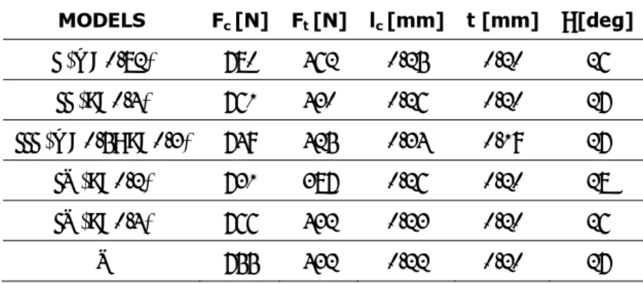
MODELS Fc [N] Ft [N] lc [mm] t [mm] φ [deg] I (m=0.82) 780 462 0.25 0.20 26 II (μ=0.4) 761 430 0.26 0.20 27 III (m=0.5; μ=0.3) 749 425 0.34 0.19 27 IV (μ=0.2) 731 387 0.26 0.20 28 IV (μ=0.4) 766 432 0.23 0.20 26 V 755 432 0.22 0.20 27
These results demonstrate that the different formulations do not provide substantial differences as far as the “mechanical results” are concerned.
Based on this consideration, the following step was to verify the thermal behaviour of the different models since comparable results can be obtained properly setting the constants if the mechanical issues are taken into account.
2.3.7
O
N THET
EMPERATURE IN THET
OOLDespite at the varying of the friction model the sensitivity is very low as far as the mechanical variables are regarded, it is very interesting to observe how the situation completely changes if thermal issues are investigated.
A thermal analysis was also carried out taking into account the different friction models. It is well known that in thermo-mechanical simulation of metal cutting a very short process time can be effectively simulated. During this limited time, many process variables do not reach steady state conditions. Among these the temperature surely plays a relevant role in the occurrence (and modeling) of different process phenomena. Anyway, a punctual prediction of the thermal aspects is allowed in the thermo-mechanical simulation only if particular procedures are implemented.
Some researchers, for instance, artificially increase the global thermal exchange coefficient. In fact, it was demonstrated that high values of h [62] allow to reach steady state temperatures in a very short time of simulation. In this way the thermal equilibrium is suddenly reached at the tool-chip interface but the temperature distribution, for instance in the tool, is quite different respect to the real one. Therefore, this procedure results more a trick than a rigorous scientific approach, thus this issue has to be accurately investigated. Besides an important factor to take into account is the friction modeling at the chip-tool interface because it is the main cause of energy generation in the thermo-mechanical analysis.
In the present study it was studied the variation of the temperature distribution in the tool when the different friction models are adopted.
An inverse approach was utilized to evaluate the global film coefficient h. More in detail, the procedure for each friction model was the following:
1. a 2D thermo-mechanical numerical simulation was run imposing a global heat transfer coefficient equal to 1000 kW/m2K. In fact, how it was pointed out by
Filice et al. [63], a value of h close to 1000 kW/m2K permits a satisfactory
agreement between the numerical data and the experimental evidences;
2. when the temperatures at the tool-chip interface reached the steady-state conditions, the simulation was stopped and the nodal temperatures on rake face were collected;
3. the obtained nodal temperatures of 2D analysis were then applied as boundary conditions for a subsequent 3D Eulerian thermal analysis;
4. the steady-state temperature were previously experimentally measured by using a proper thermocouple placed in the tool, then the error between the predicted and the experimental temperatures was calculated:
4.1 if the error was lower than an acceptable value (5%) then global interface film coefficient, h, was found;
4.2 else, return to step 1 and increase or decrease global interface heat transfer coefficient, h, according to the obtained error.
Having a look at the Table 2.8, it is possible to state that only in four cases the proposed procedure converged, allowing to calculate the temperature in the tool with an acceptable error.
Thus, the friction model heavily affects the thermal result.
More in details, even if this part of the study was focused only on one material and one process configuration, it is important to highlight that apart from small differences, the main mechanical results (i.e. forces, contact length and so on) appears practically not sensitive to friction model. On the contrary, friction becomes probably the most relevant issue in thermal analysis since it determines the rake face heating.
Table 2.8. Predicted temperature in the tool. MODELS h [kW/m2K] T FEM [°C] e% I (m=0.82) 1000 560 3.32% II (μ=0.4) 10000 551 1.67% III (m=0.5; μ=0.3) 1000000 324 40.22% IV (μ=0.2) 10000 443 18.27% IV (μ=0.4) 10000 551 1.67% V 100 545 0.55%
Taking into account this considerations the study was successively extended in order to take into account other couples of workpiece-tool, different cutting conditions and other material laws.
All these aspects will be discussed in the next paragraphs.
2.4
D
IFFERENT
C
OUPLES
T
OOL
-W
ORKPIECE
With the aim of enlarging the investigation on the role played by the implemented friction model within a 2D simulation of orthogonal cutting, the initial experimental campaign was enhanced with new orthogonal cutting experiments.
The new workpiece-tool materials utilized were: AISI 1020 - uncoated carbide ISO P25 tool (Case 2), AISI 1045 - uncoated carbide ISO P40 (Case 3),
AISI 1045 - carbide ISO P40 with a TiAlN coating (Case 4).
All the turning tests were carried out using a feed of 0.1 mm/rev and a cutting speeds of 100 m/min. The depth of cut was generally 3 mm but it was fixed equal to 2.5 mm in the Case 2. The rake angle was equal to 0°C in the Case 2, while it was equal to +10° in the other ones.
All the measurements were executed utilizing the same procedure described in the paragraph 2.3. Therefore, cutting and thrust forces were measured by using a
piezoelectric dynamometer while an optical microscope was used for estimating both the chip contact length and chip thickness. Temperatures were measured using a single wire thermocouple that was directly embedded in the tool, at a know distance from the rake face (about 0.35 mm). Table 2.9 summarizes the experimental results in terms of cutting and thrust forces, chip contact length, chip thickness and measured temperature for both the old case and the new cases.
Table 2.9. Experimental results.
Measured parameters CASE 1 CASE 2 CASE 3 CASE 4 Cutting force Fc [N] 745 920 820 710
Thrust force Ft[N] 600 463 620 386
Contact length lc[mm] 0.5 0.529 0.36 0.28
Chip thickness t [mm] 0.29 0.42 0.28 0.21 Temperature [°C] 542 483 514 417
Data in Table 2.9 were calculated as average value of 5 measures for each configuration.
In this investigation, for a second time the finite element code DEFORM-2D, was used to simulate the cutting process. For all the cases the workpiece was modelled as elastic-plastic and the tool as rigid, and 2D plane strain conditions were imposed in the simulation. Also this time the material flow stress model proposed by Oxley [56] was used in finite element code, for both AISI 1020 and AISI 1045 materials.
The investigation was restricted to the three most common friction models, namely the constant shear friction on the tool-chip interface (model I), the constant Coulomb friction on the whole tool-chip interface ( model II) and finally the sticking-sliding model (model IV). The motivation is the very broad employment of these models among the experts in the field. In addition, analysing the results obtained by using the other two models (model III and model V), it was observed that they do not provide a better prediction of the mechanical variables. Moreover both model III and model V present an important difficulty: in the first case (model III) it is necessary to fix the length of the sticking region,
while in the second case (model V) it is necessary to know the shear flow stress of the material.
The study, taking into account the results of the previous analysis, was also restricted in terms of friction coefficients.
Tables from 2.10 to 2.12 summarize the best numerical results for all the investigated cases concerning cutting and thrust forces, chip contact length and chip thickness. The Tables also report the relative errors for each parameter and the average error . e
Table 2.10. Best numerical results for each friction model (Case 2).
Model Fc [N] eFc% Ft [N] eFt% lc [mm] elc% t [mm] et% e%
I (m=0.85) 864 6.1 545 17.7 0.55 4.0 0.32 23.8 12.90 II (μ=0.90) 839 8.8 499 7.8 0.38 28.2 0.30 28.6 18.35 III (μ=0.90) 843 8.4 501 8.2 0.34 35.7 0.31 26.2 19.63
Table 2.11. Best numerical results for each friction model (Case 3).
Model Fc [N] eFc% Ft [N] eFt% lc [mm] elc% T [mm] et% e%
I (m=1.00) 747 8.9 361 41.8 0.26 27.8 0.21 25.0 25.88 II (μ=0.85) 654 20.2 240 61.3 0.18 50.0 0.18 35.7 41.80 III (μ=0.80) 667 18.7 257 58.5 0.16 55.6 0.18 35.7 42.13
Analyzing each couple of materials it is possible to state that the different friction formulations do not provide very relevant differences as far as the mechanical parameters are concerned. On the other hand, taking into account all
Table 2.12. Best numerical results for each friction model (Case 4).
Model Fc [N] eFc% Ft [N] eFt% lc [mm] elc% t [mm] et% e%
I (m=0.80) 762 7.3 417 8.0 0.20 28.6 0.18 14.3 14.55 II (μ=0.80) 760 7.0 433 12.2 0.26 7.1 0.19 9.5 8.95 III (μ=0.90) 747 5.2 431 11.7 0.24 14.3 0.19 9.5 10.18
the cases it is possible to highlight that a proper friction model and coefficient has to be selected for each specific workpiece-tool system. The best model and
coefficient for each of the investigated case is reported in Table 2.13, taking into account also the first couple workpiece-tool investigated.
Table 2.13. Best Results for each couple of materials.
Couple Model Fc [N] eFc% Ft [N] eFt% lc [mm] elc% t [mm] et% e%
1 I (m=0.90) 810 8.7 507 15.5 0.28 44.0 0.21 27.6 23.95
2 I (m=0.85) 864 6.1 545 17.7 0.55 4.0 0.32 23.8 12.90
3 I (m=1.00) 747 8.9 361 41.8 0.26 27.8 0.21 25.0 25.88
4 II (μ=0.80) 760 7.0 433 12.2 0.26 7.1 0.19 9.5 8.95
Several considerations may be developed on the data of Table 2.13; from a practical point of view, it is possible to state that all the models are able to provide sufficient predictions, also because average errors of 10-20% have to be considered as acceptable in this field. What is more, the most relevant error is caused on the contact length, probably due to the not very accurate mesh refining at the chip-rake face interface. In general, taking into account the available data, the use of Model I, setting a shear factor in the range 0.80-1.00, constitutes a good approach for friction modelling in the investigated cases. In the Case 4, in fact, Model II is the best only taking into account chip contact length.
2.4.1
T
EMPERATUREE
STIMATIONAlso this time a thermal analysis was carried out . In order to overcome the problem related to the possibility of simulating only few milliseconds of the machining process time, the strategy based on an artificial increasing of the global heat transfer coefficient h between the tool and workpiece was adopted. In particular, as in the previous analysis, a value of h close to 1000 kW/m2K was
utilized, since it permitted [63] a satisfactory agreement between the numerical data and the experimental evidences, for a specific couple workpiece-tool (AISI 1045 – ISO P20). The procedure utilized was the same as in the paragraph 2.3.7.
More in detail, the influence of the friction model on temperatures was investigated for the Cases 1 and 2, using the best coefficients for each model, according to the above reported results.
Data provided by the simulations are summarized in Table 2.14. Table 2.14. Predicted Temperature in the Tool. CASE 1
MODELS TFEM [°C] e% MODELS CASE 2 TFEM [°C] e%
I (m=0.90) 560 3.32% I (m=0.85) 535 10.33% ΙΙ (μ=0.40) 555 2.40% II (μ=0.90) 739 53.00% ΙΙΙ (μ=0.40) 565 4.24% III (μ=0.90) 670 38.72%
It can be observed that the numerical temperatures are strictly dependent on the friction model and on the selected constants. This is consistent with theory since a relevant quota of heat is generated in the secondary shear zone. However, the sensitivity of temperature on the friction model and coefficient is very high and all the simulations are influenced by the choice of the h value. It seems clear that, while the mechanical variables can be estimated properly setting the friction model, further efforts are required as far as the thermal aspects are regarded.
In fact, also the strategy to increase the global heat transfer coefficient is not completely physically consistent, even if it permits to obtain a quicker reaching of thermal steady state.
Furthermore, it is possible to state that a generally applicable model is not yet available as regards the thermal simulation.
On the other hand , since a proper friction model and coefficient have to be selected for each specific workpiece-tool system, the analysis was extended to the study of friction related to material modelling as shown in the following sections of this chapter.
2.5 D
EPENDENCE OF
M
ACHINING
S
IMULATION
E
FFECTIVENESS ON
M
ATERIAL AND
F
RICTION
M
ODELLING
deeper understanding of the aspects involved. With this aim, the couple workpiece – tool was fixed, as well as the heat transfer coefficient at tool - chip interface, while different cutting conditions were taken into account. In addition, the attention was focused on the effects of different combination of friction models and material laws, utilized to describe the workpiece material behaviour.
Several researches were focused on the effects of flow stress and friction models in finite element simulation. Childs [64] utilized several flow stress laws, proposed in the literature, with the aim of analyzing their effects on the prediction of process mechanics in the primary and the secondary shear zones. He found that, despite the differences existing in their structure, the material laws provided similar numerical flow stress values in the primary shear zone, but caused large differences in the secondary shear zone. According to the author, this discrepancy was mainly due to the friction law since machining has very severe friction conditions and small changes in friction modelling can cause large changes in chip formation.
The above conclusions were confirmed by Ozel [60]. In particular, he found that machining modelling is greatly influenced by two major factors: a) flow stress characteristics of the work material, and b) friction characteristics at the tool-chip interface. However, in the analysis, he took into account only the influence of the friction law.
A sensitivity analysis of the influence of flow stress and friction laws was recently proposed by Sartkulvanich et al. [58] even if their study was more oriented on the flow stress aspects. Furthermore, they utilized a power law obtained by fitting the data from Hopkinson’s bar tests, and two friction laws were utilized in their investigation.
Recently, Childs and Rahmad [65] recognized that a complete analysis requires one to take into account the effects of the flow stress and of the friction law at the tool-chip interface. However, their study was oriented on a sensitivity analysis of the strain-hardening data on the main cutting variables (cutting force and thrust force) using several FE codes.
According to the state of the art, it is evident that there is a necessity to carry out a wider analysis aimed at investigating the influence of both material flow stress laws and friction models on the effectiveness of FE simulations of cutting processes.
This is the objective of this study, which is focused, for sake of simplicity, on the simulation of an orthogonal cutting process of a plain-carbon steel (AISI 1045) utilizing different material laws and friction models. Four rheological models were considered for the material, as well as three different friction laws. For each law, several friction coefficients were used generating a very extensive plan of finite element simulations, which constitutes the knowledge base of this research. The different mechanical variables predicted using numerical simulations were compared with the experimental results.
2.5.1
E
XPERIMENTALT
ESTS ANDN
UMERICALS
IMULATIONSAn experimental investigation was carried out in order to acquire the necessary data to validate the numerical predictions. In particular, a few cutting tests were run on a lathe, reproducing orthogonal cutting conditions.
The workpiece material was AISI 1045 steel, while the cutting tool was an uncoated carbide ISO P30, with a rake angle of 0°, a relief angle of 6°, and an edge radius of 0.05 mm. The width of cut was 3mm. The tests were executed without any lubricant at the tool–chip interface, utilizing the values of cutting speed and feed rate reported in Table 2.15. All the experiments were repeated three times, showing an uncertainty of ± 6-10% (95% confidence interval).
Table 2.15. Cutting conditions. CASE Cutting Speed
(m/min) Feed Rate (mm/rev) 1 100 0.1 5 150 0.1 6 100 0.15
Different mechanical variables were detected during the tests. Cutting and thrust forces were measured by using a piezoelectric dynamometer, while an optical microscope was used to estimate both the chip contact length and chip thickness. Table 2.16 shows the average experimental results of cutting and thrust forces, chip contact length, chip thickness and shear angle.
Table 2.16. Experimental results.
TEST CASE 1 5 6
Cutting force Fz [N] 745 715 1027
Thrust force Ft[N] 600 522 749
Contact length lc[mm] 0.50 0.53 0.60
Chip thickness t [mm] 0.288 0.220 0.355 Shear angle φ [deg] 19.0 24.4 23.0
In this investigation, the finite element code SFTC-Deform-2D was utilised [66]. The workpiece, modelled as rigid-plastic, was initially meshed by means of 3000 iso-parametric quadrilateral elements while the tool, modelled as a rigid body, was meshed into 1000 elements (Figure 2.5). It is worth pointing out that the global heat transfer coefficient at the tool-chip interface, h, was fixed equal to 1000 kW/m2K taking into account some previous studies [67].
ST SH ST SH SH SH SH ST ST
Velocity boundary conditions ST=heat transfer allowed
SH=heat transfer not allowed
2.5.2
M
ATERIAL ANDF
RICTIONM
ODELLINGAs mentioned, four different constitutive models were tested in order to model the plastic behaviour of AISI 1045 steel.
The first one (indicated as M1) is the model originally proposed by Oxley [56]; the effective flow stress is computed as an exponential function of the effective strain ε: (7) σ = 1 1 n ε σ
with σ1 being the strength coefficient and n1 the strain-hardening exponent.
Both σ1 and n1 are considered as functions of the parameter velocity-modified
temperature, Tmod, which includes the effects of strain rate, , and temperature ,
T
.
ε
1. The velocity-modified temperature parameter was proposed by McGregor and
Fisher [68] and is defined as:
⎟⎟ ⎟ ⎠ ⎞ ⎜⎜ ⎜ ⎝ ⎛ − ⋅ = 0 . . 1 mod 1 log ε ε ν T T (8)
where νand are constants depending on the workpiece material, available in [
0 .
ε
56]. The relationships σ1 vs. Tmod and n1 vs. Tmod have been experimentally
established using high speed compression tests [56].
The second utilized flow stress equation is the well known Johnson-Cook model [69] (indicated as M2):
(
)
⎟⎟ ⎠ ⎞ ⎜ ⎜ ⎝ ⎛ ⎟⎟ ⎠ ⎞ ⎜⎜ ⎝ ⎛ − − − ⋅ ⎟⎟ ⎟ ⎠ ⎞ ⎜⎜ ⎜ ⎝ ⎛ ⎟⎟ ⎟ ⎠ ⎞ ⎜⎜ ⎜ ⎝ ⎛ + ⋅ + = m room melt room n T T T T C B A 1 ln . 1 0 . ε ε ε σ (9)where σ is the stress (MPa), ε the strain, the strain rate (sε. -1), the reference
strain rate (s
0 .
ε
-1), and A, B, C, n, m are the material flow stress parameters.
In particular, the J-C material constants in model M2 were identified through high strain rate mechanical testing using the Split Hopkinson’s Pressure Bar
![Table 2.2. Constant shear friction on the whole tool-chip interface (model I). m F c [N] e Fc % F t [N] e Ft % l c [mm] t [mm] φ [deg] 0.30 721 3.2% 328 45.3% 0.17 0.16 30 0.50 706 5.2% 354 41.0% 0.18 0.18 29 0.60 720 3.4% 385 35.8% 0.21 0.18](https://thumb-eu.123doks.com/thumbv2/123dokorg/2881995.10410/26.892.215.699.155.387/table-constant-shear-friction-tool-chip-interface-model.webp)