1
University “Federico II” of Naples, The Center for Advanced Biomaterials for Healthcare @ Istituto Italiano di Tecnologia
Azobenzene-based Biomaterials
as Dynamic Cell Culture Systems
PhD thesis
PhD Program in Industrial Product and Process Engineering (XXXI cycle)
Selene De Martino
Tutor Prof. Paolo A. Netti
Supervisor Dr. Silvia Cavalli
Coordinator Prof. Giuseppe Mensitieri
3
AZOBENZENE-BASED BIOMATERIALS AS DYNAMIC CELL CULTURE SYSTEMS A THESIS SUBMITTED IN PARTIAL FULFILLMENT OF THE
REQUIREMENT FOR THE DEGREE OF DOCTOR OF PHILOSOPHY IN
INDUSTRIAL PRODUCTS AND PROCESS ENGINEERING
AUTHOR
Selene De Martino
SUPERVISOR
Prof. Dr. Paolo A. Netti ADVISORS
Dr. Silvia Cavalli
COORDINATOR
Prof. Dr. Giuseppe Mensitieri
COLLABORATION
4
Table of Contents
Introduction ... 7
1.1 Tissue Engineering ... 7
1.2 Cell-Material Interaction ... 7
1.3 Static Cell Instructive Materials (CIMs) ... 9
1.4 Dynamic CIMs ... 11
1.5 Azobenzene ... 14
1.5.1 Azobenzene Photoswitching without UV Light ... 16
1.6 Azobenzene-containing Polymer ... 17
1.6.1 Photo-orientation ... 18
1.6.2 Macroscopic Motion ... 19
1.6.2.1 Regular Surface Reliefs by Holographic Light Irradiation ... 21
1.6.2.2 Regular Surface Reliefs by 1D Gaussian Laser Beam ... 23
1.6.2.3 Randomly‐distributed Surface Reliefs by One‐Beam Irradiation ... 27
1.6.3 Directional Photofluidization Lithography (DPL) ... 28
1.7 Azopolymers as Dynamic CIMs ... 31
1.8 The role of Topography in the Regulation of Stem Cells ... 34
1.9 Aim and Outline of the Thesis ... 36
Chapter 2 ... 38
Dynamic Topographic Control on Mesenchymal Stem Cells by Photoresponsive Azopolymers .... 38
2.1 Introduction ... 39
2.2 Materials and Methods ... 41
2.2.1 Substrate Preparation. ... 41
2.2.2 Optical Pattern Inscription. ... 41
2.2.3 Cell Culture Experiments ... 42
5
2.2.3.2 rt-PCR analysis ... 43
2.3 Results and Discussion ... 44
2.3.1 Pattern Fabrication ... 44
2.3.2 Pattern Erasure ... 47
2.3.3 Cell Adhesion, Orientation and Elongation on Static Pattern ... 49
2.3.4 Cell Response to Dynamic Pattern ... 53
2.3.5 Stem Cell Differentiation in Static Conditions ... 56
2.3.6 Stem Cell Differentiation on Dynamic Pattern ... 59
2.4 Conclusion ... 61
Chapter 3 ... 62
Dynamic Manipulation of Membrane Curvature by Light-Driven Reshaping of Azopolymer Substrates ... 62
3.1 Introduction ... 63
3.2 Materials and Methods ... 65
3.2.1 Micro-pillar array fabrication ... 65
3.2.2 Optical Setup ... 66
3.2.3 Cell culture experiments ... 67
3.2.3.1 Transfection ... 67
3.2.3.2 Immunostaining ... 67
3.2.3.3 Live/dead cell viability assay ... 68
3.3 Results and Discussion ... 69
3.3.1 Pillars Reshaping by Optical Set-up ... 69
3.3.2 Pillar Reshaping by Confocal Microscopy ... 72
3.3.3 Pillar Reshaping with Live Cells ... 74
3.3.4 Membrane Curvature-Dependent Actin Polymerization on Static Azopolymer Array ………..75
3.3.5 Membrane Curvature-Dependent Actin Polymerization on Dynamic Azopolymer Array ………..77
6
3.4 Conclusion ... 80
Chapter 4 ... 81
Hydrogel Scaffolds Containing Azobenzene as Dynamic Cell Culture Systems ... 81
4.1 Introduction ... 82
4.2 Materials and Methods ... 84
4.2.1 Synthesis of Azobenzene-based Crosslinkers ... 84
4.2.1.1 Azo-crosslinker 1 ... 84
4.2.1.2 Azo-crosslinker 2 ... 85
4.2.2 Synthesis of Acrylamide-modified Gelatin B ... 87
4.2.3 Gelatin Photoresist Preparation and Two-Photon Polymerization ... 87
4.2.4 Cell Culture Experiments ... 87
4.2.4.1 Cell Imaging ... 88
4.2.4.2 Live/Dead Cell Viability Assay ... 88
4.2.5 Photostimulation ... 88
4.3 Results and Discussion ... 90
4.3.1 Hydrogel Scaffold Preparation ... 90
4.3.1.1 Azocrosslinker characterization ... 90
4.3.1.2 Acrylamide Modified Gelatin Hydrogels characterization ... 95
4.3.2 Fabrication of 3D Scaffolds ... 97
4.3.3 Photostimulation of the gelatin squared structures ... 99
4.3.4 Biological Investigation ... 100
4.4 Conclusion ... 105
Conclusion and Future Perspectives ... 106
7
Chapter 1
Introduction
1.1 Tissue Engineering
Tissue engineering is a multidisciplinary research area, which involves several contributions from biology, medicine and engineering, all merged in the field of regenerative medicine. Its goal is to develop technologies to repair or replace tissues without the complication of chronic immuno-suppression.1 More specifically, tissue engineering combines cells, scaffolds and bioactive factors to direct the in vitro formation of new tissues or organs. In order to recreate synthetic scaffolds with optimal properties to support cell attachment and tissue growth, tissue engineering is focused on in depth studies of the extracellular matrix (ECM).2 The native ECM is a complex and dynamic network of proteins that provides both structural and biochemical support to surrounding cells.3 For a long
time, the ECM has been considered as a passive cell support, while recently this concept has been revisited.4 In fact, the ECM is certainly recognized as an active structure able to promote, guide and sustain cellular functions. The interaction of cells with the ECM plays a key role in the regulation of multiple biological responses of cells. In fact, the ECM provides simultaneously mechanical, topographic, and biochemical cues that can influence cell attachment, morphology, proliferation, migration and differentiation.5 The field of tissue engineering attempts to translate this knowledge to biomaterial science in order to have a rational control of cell-scaffold interaction. Biomaterials, defined as encompassing natural or synthetic materials that interact with biological systems, serve as the scaffolding upon which cells build tissues.4 To sum up, tissue engineering research is currently focused on applying knowledge of the biological characteristics of native cellular environment to develop even more innovative and efficient biomaterial-based constructs and cell-instructive platforms.
1.2 Cell-Material Interaction
It is well known that a crosstalk occurs at the cell-material interface and it has a profound influence on the cell behavior.6 Thus, revealing the basic role of each cues is extremely important in biomaterial development, cell biology, tissue engineering and regenerative medicine. Artificial matrixes, in fact, aim to mimic the ECM behavior, interacting with cells and instructing them in order to promote tissue
8
regeneration events. Understanding the interaction between the cell and its external environment is fundamental for replicating basic cell-ECM functions in biomaterials. As matter of fact, a big part of this field of research is focused on the development of new cell instructive materials (CIMs), as smart engineered environment that can stimulate cells and guide them to express specific biological features.7 In particular, the possibility to pattern the material surface at relevant length-scales allows to selectively induce diverse cellular responses. Furthermore, the variation of biomaterials’ properties such as stiffness, roughness, ligand density, surface charge, hydrophobicity can affect cell responses. In fact, different topographic features can activate certain mechanotransduction processes which are involved in complex biological progressions, such as morphogenesis, tissue repair, and tumor progression.8-9 The mechanotransduction process can be described as a simple model where mechanical input influences cells’ intrinsic mechanical properties which is then transduced into specific cellular outputs.10 The cell-ECM communication is mediated by membrane receptors – e.g., integrins, laminin receptors and syndecans – or ECM-modifying proteins, such as matrix metallo proteinases (MMPs).11 Integrins play a crosstalking role during the biological recognition and signaling events between the ECM outside the cell and the cytoskeleton inside the cell. Each integrin consists of a heterodimer made from one α and one β subunit. Both subunits are type I transmembrane glycoproteins with relatively large extracellular domains.11 The process of integrin-mediated cell adhesion comprises a cascade of four different, partly overlapping, events: cell attachment, cell spreading, organization of actin cytoskeleton and formation of focal adhesion. During these steps, integrins are involved in physical anchoring as well as in signal transduction processes through the cell membrane.12 In summary, the cell-ECM crosstalk regulates, through integrins, the cell behavior
by influencing cell proliferation, survival, shape, migration and differentiation. These processes are dynamically regulated because ECM is constantly undergoing remodeling, assembly and degradation particularly during the normal processes of development, differentiation and wound repair.13,14 The development of novel biomaterials able to understand this crosstalk, mimicking the natural cell environment and influencing cell functions over time, is the current challenge in the tissue engineering.
9 1.3 Static Cell Instructive Materials (CIMs)
It is known that cells are sensitive to the chemical composition, physical properties and biologically functional moieties of artificial matrix where they are seeded.6 These signals modulate cell adhesion, orientation, motility, and intracellular signaling pathways that regulate transcriptional activity and gene expression.15 Many attempts have been carried out towards controlling the material surface with nano and micromachining approaches aiming to control cell guidance and polarization at the cell-material interface.16 In particular, material surface properties can be modulated by physical patterning or creating other physical interactions such as chemical binding or charge injection.17 In the case of surface patterning, micron, submicron and nanoscale topographies of diverse shapes can regulate different cellular response such as proliferation, migration, and differentiation.18-21 It is interesting to note that different cell types such as fibroblasts, osteoblasts, epithelial cells, neuronal cells, and more recently stem cells have dissimilar responses.22 One of the main goals in biomaterials’ design is to mimic the structure and function of the native ECM. While the chemical factor effects on cell behavior have been extensively analyzed, topographic cues are relatively less explored.23 Almost a century ago, the earliest surface morphology effect on cells was discovered and it was found that cells topographic cues, independent of biochemistry, may have significant effects upon cellular behavior. The cell response to topographies depends on cell type, cell-cell interactions, and the geometry of the patterns.6 However, the most relevant effects are observed when topographies exhibit dimensions
comparable to those of cells. It is reported that patterns in the range of 70 nm up to 2-5 μm show relevant effects on cells.6 Furthermore, the presence of nanometric features alter the surface properties
of materials (surface energy, wettability) modifying also the preferred protein adsorption. In this way, the geometric characteristic of topographic patterns creates also a chemical pattern making some surfaces more accessible (i.e. the top of ridges and pillars) than others (i.e. bottom of grooves and pits) for cell lamellipodia and filopodia adhesion.6 With the development of advanced materials, surface patterning affords a unique and powerful tool to understand cell–material interactions.24 Many studies have been conducted on features in the micrometer range but recently nanoscale topography has received major attention because of its resemblance to in vivo surroundings.25 For instance, the investigation of the native basement membranes from a variety of animal sources has demonstrated that ECM layers possess a complex topography consisting of intertwining fibers mixed with meshwork of pores, ridges and other features of micro-nanometer sized dimensions.2621 Reproducing the linear pattern in vivo, generally results in significant alterations to cell morphology and cytoskeletal arrangement, specifically cells align along the long axis of the groove with actin and microtubules also organized parallel to grooves.27-28 Hamilton et al. investigated the adhesion,
10
spreading and migration of human periodontal ligament (PDL) fibroblasts in response to continuous and discontinuous topographic cues in the nanometric range. They showed that PDL fibroblasts adhered to and spread on all tested surfaces, with initial spreading and focal adhesion formation slower on discontinuous nanogrooves while they appeared highly elongated on both types of nanogrooves after 24 h post seeding.29 Ahn et al. investigated topographies constituted by nanopots with variable nanopost densities able to guide hMSCs making different cell fate decisions.30 In particular, osteogenic differentiation was favored by greater distance between posts, whereas smaller post-to-post distances were associated with adipogenesis.30 In general, a variation of topographic features such as shape, size, distribution, height can differently instruct cells. For example, it was reported that expression of osteogenic markers of human mesenchymal stem cell (hMSCs) enhanced both on nanopits randomly placed (50 nm holes),31 nanotubes (100 nm diameter) and ridge/groove with 400 nm pitch.25 Until now, a large number of studies have fabricated substrates that contain microscale and nanoscale features on otherwise 2D surfaces. It is important bear in mind that these substrates only provide cues to the portion of the cell that is in contact with the surface and essentially limit cell motility to two dimensions. This property, for example, induces to polarize only a segment of the cell’s membrane that can interact with the ECM and neighboring cells, leaving the rest of the cell exposed to a different environment. Biological processes analyzed on 2D substrates can bring to imprecise results because they are limited in their complexity compared to the native tissue environment.32
Effectively, also if 2D cell constructs have provided the base for our nascent interpretation of complex biological phenomena, we can agree upon insufficiency of examining hierarchical biology in just two dimension. Therefore, realization of the well-defined 3D artificial ECM is important from the perspective of tissue growth for systematic studies of fundamental aspects of 3D cell–cell and cell– matrix interactions in vitro. As a result, biologists and bioengineers alike have investigated many three-dimensional scaffolds that recapitulate aspects of the native cellular microenvironment for in vitro cell culture. For example, Liu et al. reported a study where they compared how various biomaterial-based culture conditions, e.g., 2D vs. 3D scaffolds and static vs. dynamic, were able to influence the global gene expression profile of differentiated embryonic stem cell (ES).33 They reported a higher expression level of extracellular matrix (ECM)-related genes on 3D dynamic scaffolds compared to 2D scaffolds and 3D static scaffolds. Effectively, a 3D scaffold possesses major characteristics resembling those of the 3D-cell environment. Fibrous collagen or matrigel matrices have been commonly used to study 3D cell behavior, but these matrices have a random pore size and are structurally and chemically ill-defined. So much attention has been focused on materials that can demonstrate a distinct efficacy as matrices for 3D cell culture.34 Hydrogels are an important
11
class of soft materials that can be fabricated in the form of 3D microperiodic structures.35-37
Bioprinting of 3D hydrogels has emerged as a powerful alternative for the fabrication of 3D structures (typically collagen, HA, alginate, photocured acrylates, or modified copolymers) with faithfully mimic the structures of native tissue.38 Furthermore also the direct laser writing (DLW) is shown to be an advantageous and versatile technique to fabricate tailored 3D cell-culture scaffolds.39 In particular, the two-photon polymerization (2PP) technique allows the realization of arbitrary 3D structures with submicron spatial resolution.40 Ovsianikov et al. combined 2PP to fabricate highly porous 3D scaffolds of acrylated poly(ethylene glycol) and laser-induced forward transfer (LIFT) as a cell-seeding tool to produce arbitrary multicellular 3D constructs with unprecedented flexibility and precision.41
1.4 Dynamic CIMs
An ideal platform for the in vitro study of cellular response should include the fabrication of tridimensional structured platforms that are able, at the same time, to deliver biochemical, topographic and mechanical cues with a fine spatial-temporal control.42 In order to unravel the complex mechanisms at the basis of cell-material interaction, many reports in the literature make use of advanced microfabrication techniques to structure both synthetic and nature-derived materials in complex 3D architectures with “smart” functionalities. We define smart, biomaterials able to change one or more of their properties when exposed to an external electrical, thermal, optical, and mechanical stimulus. So these responsive materials also defined as “Dynamic Cell Instructive Materials” have attracted considerable attention due to their potential to attain unprecedented levels of space/time control over biomolecular processes at engineered interfaces, including the control over reversibility of the signaling/cue. Therefore, in vitro platforms that recapitulate dynamic in vivo signaling can lead to an enhanced understanding of fundamental biological processes. For this reason, in the last years the scientific community has recently shown an increased effort to design dynamic substrates that can communicate active physical cues to cells in a more biomimetic context. Among different cues, as introduced above, topography plays an integral role in influencing cell behavior. Takayama and co-workers reported the first application of dynamic topography to cultured cell using reversible poly(dimethylsiloxane) (PDMS) surfaces. The C2C12 myoblast cell morphology was dynamically altered using surface array transitions. The initial wavy micropattern was obtained by plasma oxidizing, it was introduced and removed in the presence of cells applying and releasing compressive strain (Figure 1.1 a-d).43 Also Guvendiver et al. reported a strain-responsive buckling
12
patterns on PDMS substrates used to dynamically and spatially control hMSCs organization. Preferential alignment of hMSCs was completely eliminated after the topography switch from patterned to flat, and could be reversibly repeated for several cycles.44 Furthermore, also if these
preliminary findings are innovative, these materials are not suitable for dynamic in vitro analysis because the pattern complexity and versatility are relatively limited. Kirschner and Anseth demonstrated the possibility to control in real-time cell morphology through the controlled erosion of a photolabile PEG-based hydrogel system with tunable microtopography. 45 hMSCs were initially seeded onto smooth surfaces, which were in turn patterned using photolithography into an anisotropic channel pattern and then an isotropic square pattern. Cells exhibited a round morphology on the smooth pattern, an elongated shape along the channels, and again a round morphology on isotropic squares.45 An alternative approach to fabricating reversible surface features is by exploiting the unique properties of shape-memory polymers (SMPs). They are one of the most important examples of systems that can exposing a changing topographic signal by an external heat trigger. SMPs are a class of active materials that have the ability to memorize a permanent shape through crosslinking. They are manipulated and then fixed to a temporary shape by an immobilizing transition and later, they can recover the permanent shape by a triggering event. This behavior allows a change of superficial properties of materials. In the context of dynamic CIMs, the challenge is developing engineering biocompatible surfaces enable to strict regulate the shape-memory effect in terms of well-defined geometry and biologically relevant surface transformations under physiological conditions.46
Henderson and coworker presented SMP substrates able to change surface topography during cell culture in order to control cell behavior.47 They embossed on initially flat SMP substrate a temporary
topography of parallel micron-scale grooves and successively, the shape memory was triggered through a change in temperature activation that allowed topographic transformation back to the original surface in the presence of mammalian cells.47 Similar, Le et al. proposed a dynamic topographic control of mesenchymal stem cells by culture on responsive Poly(ε-caprolactone) surfaces. The cell morphology was switched from highly aligned to stellate shaped in response to a surface transformation between a 3 μm × 5 μm channel array and a planar surface at 37° C (Figure 1.1 ef).46
13
Some distinct advantages of the shape memory process are the ability to program complex shapes in many length scales (from the nano- to macroscales) but despite the promising results obtained with these materials, this shape-memory activity is often not reversible, or not suitable for biological applications.48 In general, the external stimuli capable of regulating the ‘on-off’ features of surface properties are not limited to temperature alone. For example, light arises much interest among Figure 1.1 a-d (Left side) Schematic of the process of reversibly introducing microfeatures into the substrate surface; after being prepared for cell culture, substrates are compressed to obtain wavy features and uncompressed to remove the features. Micrographs (on the right) show cell behavior on the reconfigurable surface b) before c) during and d) after compression – cells orient from random to aligned and back to random. e) GFP-hMSC cells cultured on temporary 3 μm × 5 μm channel SMP arrays demonstrated significant alignment along the channel axis. f) The cell morphology changed to stellate shaped in response to the surface transformation, switching the patterned surface to flat by heat. (Reprinted from Biomaterials 2008, reference 43, and Advanced materials 2011 reference 46)
14
possible external triggers (electric or magnetic field, heat etc.) because beyond its unique spatial and temporal controllability, it is a kind of clean energy, which can be manipulated conveniently and controlled in situ. In this context, interesting is to fabricate scaffolds with photoresponsive molecules include reversible photoresponsive azobenzene, spiropyran and irreversible photocleavable and photolinkable compounds.49 Their photochemical reactions can be used to induce switching in surface physicochemical properties involving different mechanisms: photo dimerization, photo-induced intramolecular bonds or photo-isomerization. Nowadays, azobenzene is the most widely used molecule in light-controlled systems.50-52 It has undoubtedly attracted most attention due to its strong photo-switching effect, simple molecular structure, reversibility, speed and simplicity of incorporation.53 In fact, when illuminated with a specific type of light, the azobenzene molecules undergo to isomerization process from the more stable trans isomer to the less stable cis isomer, that can significant changes optical, geometric, mechanical and chemical properties of azobenzenes. Furthermore, these photo-induced variations can be often transferred from molecules to large host systems containing azobenzenes. In fact, interesting photo-mechanical effects come out when azobenzenes are incorporated into biopolymers and other polyelectrolytes.54
1.5 Azobenzene
Azobenzene is an aromatic molecule in which an azo linkage (-N=N-) joins two phenyl rings. It undergoes a rapid and reversible photoisomerization, converting between the stable trans configuration and a meta-stable cis form (Figure 1.2).
This photoisomerization is completely reversible and free from side reactions. Trans azobenzene is near planar with a dipolar moment around zero. It shows a n-π* band at 440 nm and a strong π-π* transition near 320 nm. Cis azobenzene adopts a bent conformation with a dipolar moment different from zero. It also has a strong n-π* band near 440 nm and shorter wavelengths bands at 280 nm and 250 nm. Upon irradiation, a fraction of the trans azobenzene is converted to the cis form, which can thermally revert to the more stable trans state on a timescale dictated by the particular substitution pattern of molecules. Thermal cis-to-trans relaxation, however, produces essentially 100% of the
15
trans isomer. This isomer can be regenerated also by irradiation at 450 nm on a picosecond timescale. Photophysical and photochemical properties of azobenzene derivatives strongly depend on the substituents on the azo groups.48 As described by Rau et al.55, the azo chromophores are typically
divided into three classes, based upon spectroscopic characteristics: 1) azobenzene type molecules, which are similar to the unsubstituted azobenzene with a low-intensity n-π* band in the visible region and a much stronger π-π* band in the UV; 2) aminoazobenzene-type molecules, which are ortho or para substituted with an electron-donating group, with the n-π* and π-π* bands much closer; 3) pseudo-stilbene, which are substituted at 4 and 4’ positions with an electron-donating group and electron withdrawing group (Figure 1.3).
In the latter case, the strong π → π * absorption with charge-transfer (CT) character is a dominant feature in the visible spectrum, and the n→ π * transition is hidden by this strong band. Substituents on the phenyl rings may strongly influence the position and shapes of the azobenzene absorption bands and the rate of thermal cis to trans relaxation. Azobenzenes with para donor substituents can show strongly red-shifted π-π* bands but at the same time faster thermal relaxation process. This behavior derived by similar dipolar character between the thermal transition state and the excited state. Azobenzenes can be synthetized with spectroscopic properties particularly appropriate for specific applications. Actually, substitutions at ortho position on the phenyl rings introduce steric effects able to slow the thermal relaxation process of cis-trans isomerization. This effect is not observed with para or meta substituted molecules on phenyl rings. In summary, by varying the nature of ortho substituents, together with the number and nature of meta and para substituents, it is possible Figure 1.3 Chemical structures and UV/Vis absorption spectra of (1) azobenzenetype, (2) aminoazobenzene-type and (3) pseudo-stilbene-type azo compounds. (Reprinted from Chemistry-A European Journal 2017, reference 65)
16
to tune spectroscopic properties of azobenzene (longer wavelengths, good thermal stability). Exploring the wide possibilities of chemical modifications of the azobenzene unit, open up a wide range of investigations with new azoderivatives that can be triggered by visible or even IR light. The choice of an azobenzene is strongly related to the properties necessary for a certain application and its introduction in a polymer can have a wide range of possible macroscopic effects.56
1.5.1 Azobenzene Photoswitching without UV Light
As introduced, one emerging issue in biomaterial science is the elaboration of bistable molecular switches that can be controlled with visible light only. The majority of applications of azobenzene as a molecular switch uses UV light to trigger trans to cis isomerization. In biological systems, UV light is highly scattered and can induce toxicity effects. For instance, the need of using UV light to induce the switching processes implies serious limitations in living systems. In the light of biological applications, it has been of considerable interest to design azobenzene photoswitches with particular aspects concerned the cis/trans ratio in the photostationary state, the lifetime of the two isomers and the stability over time.57 A variety of azobenzenes with high conversion efficiency isomerizable in the visible range have been identified. Substitution of all four ortho positions of azobenzene with methoxy groups or Cl or Br atoms, or C2 bridged compounds allowed to obtain azobenzenes with slow thermal cis to trans relaxation facilitating production of large fractions of the cis isomer.58-59
Following a related strategy, Knie et al. designed a new family of azobenzenes fully addressable in the visible region by introducing fluoro substituents ortho to the N=N bond.60 Ortho‐
fluoroazobenzenes showed high photoconversions, and unprecedented robust bistable character. Furthermore, particularly interested was also the introduction of Sulphur at the ortho positions of azobenzenes that leads to a >20 nm red shift as well as a significant increase in the intensity of the longest wavelength absorption bands of the trans isomers.61 Woolley and co-workers reported the synthesis of azobenzene with methoxy groups in the ortho positions of the two phenyl rings in which long switching wavelengths are combined with relatively slow thermal relaxation rates and high cis-state yield (Figure 1.4).62
17
In trans state, it shows a strong π-π* band around 320 nm while a slight bathochromic and hyperchromic effect for the n-π* band relative to parent compound (same structure without orto-substituted). In cis state, the absorption bands are not subjected to spectroscopic variation. This means that the n-π* transition of the cis isomer occurs at significantly lower wavelengths (36 nm) compared to the analogues transition of its trans isomer. The split between n-π* bands of trans and cis isomers allows the switching of this azobenzene completely in visible range, trans-to-cis isomers using green light (530-560 nm) while reverse cis-to-trans photoswitching with blue light (460 nm) (Figure 1.5). In addition, this azobenzene shows interesting properties: the half-life of the cis isomer is longer that parent compound so that an intense light source is not required in order to maintain a substantial fraction of the cis isomer; very good solubility in aqueous solution for use in a biological application; multiple rounds of photoisomerization; and even constant high-intensity irradiation with green light (70 mW/cm2) for ∼1 h, without evidence of photobleaching or photo-oxidation.62
1.6 Azobenzene-containing Polymer
The azobenzene moiety, incorporated in different materials either doped into a matrix or covalently attached to a polymer (amorphous and liquid-crystalline (LC) systems), can be used as a “probe” to induce light driven changes of material properties.52 In fact in azopolymers, the photoisomerization induces conformational changes of azobenzene and consequently of the polymer chains that in turn lead to macroscopic variations in the chemical and physical properties of surrounding.63 Furthermore, in the azobenzene-containing polymers, the photo-responsive behavior of the azo groups is combined with the inherent stability of polymers to obtain stable and tunable materials.64 Azobenzene Figure 1.5 Photoisomerization of the 4,4’-diacetamidoazobenzene bearing o-methoxy groups measured in ACN at 25°C
18
functionalized monomer can be attached to the side chain, main chain and end chain of the polymer, or it can be used as cross-linker. The point of attachment to a polymer chains, the size, the shape and the conformation of chromophore play an important role in determining the effective free volume available during the isomerization.
1.6.1 Photo-orientation
Azobenzene chromophores can be photo-oriented by linear polarized light (LPL). This behavior is typical of pseudo-stilbene-type azo compounds characterized by a rapid trans-cis-trans isomerization upon light illumination. The constant and fast cyclic photoisomerization activity results in series of motions that can take place at molecular, nanoscale and micrometer levels.63 Only azobenzene groups orientated with a transition dipole axis along the polarization of the light will absorb and consequently photo-isomerize. The probability of absorption varies as cos2ϕ, where ϕ is the angle between the light
polarization and the azobenzene dipole axis. Thus, azo-molecules orientated parallel to the light polarization will absorb, while the chromophores with dipole axis perpendicular to the light will not. For a given initial angular distribution of chromophores, many will absorb, convert into the cis form, and then revert to the trans form with a new random direction. Thus, there is a net depletion of chromophores aligned with the light polarization, with a concomitant increase in the population of chromophores aligned perpendicular (Figure 1.6).65 Thus, optical dichroism as well as birefringence is induced in polymer films.
19 1.6.2 Macroscopic Motion
The photoisomerization at micrometer scale level is observed in an organized environment such as liquid crystal (LC), Langmuir-Blodgett films and monomolecular films. Azobenzenes are robust and anisotropic molecules that with suitable substitutions can show liquid crystalline behavior.66 Instead of amorphous materials where there is not a preferential direction for photo-deformation, liquid crystalline elastomers (LCEs) with anisotropic physical properties allow a precise control in two and three dimensional motions. LCEs in particular are promising materials for artificial muscles because coupled both properties of LC (order) and that of elastomers (elasticity).52,67 The incorporation of
azobenzene mesogenes into LCEs can induce a reduction in the nematic order and causes a contraction of the films upon exposure to UV light as a result of a photochemical reaction of the photochromic moiety.68 Furthermore, by their incorporation, it also possible observes three‐ dimensional movement (bending, oscillating, twisting and swimming) of LCE films by irradiation with light.69 Finkelmann et al. reported a pioneering work on large contractions of liquid crystalline networks (LCNs) containing azobenzene moieties by light.70 Successively, Ikeda et al. reported an anisotropic bending and unbending induced by light of LCGs and LCNs, cross-linked polymer films containing an azo- benzene moiety and a diacrylate-azobenzene moiety. The absorption of photons occurs only in the surface of the film due to the high absorption coefficient of azobenzene so the volume contraction is induced only in the surface region of the cross-linked LC polymer film upon Figure 1.6 Photo-induced orientation of azo compounds in solid state. a) The azo compound aligned along the polarization direction of the incident light (I) absorbs light and isomerizes. The azo compounds aligned in other directions (e.g., II, III, and IV) can absorb the incident light with a lower probability than I and can be photoisomerized. Azo compounds aligned perpendicular to the polarization direction (V) cannot absorb light and remain fixed, because their transition dipole axis and the light-polarization are perpendicular to each other. b) Irradiation of an isotropic azo-containing sample in solid state induces orientation of azo compounds in the direction perpendicular to the polarization direction. Circularly polarized light removes the orientation. (Reprinted from Chemistry-A European Journal 2017, reference 65)
20
irradiation.70 Furthermore, R. Yin et al. proposed an interesting crosslinked liquid crystalline
polymers containing azotolane moieties in side chains which show a photoinduced bending and unbending behavior upon irradiation with sunlight, according to the trans–cis photoisomerization of the azotolane moieties.71 At micrometer level, we can observe the massive movement of the polymer material because it is not limited only to the mesogenic chromophore but involves polymer chains. This kind of isomerization usually occurs in polymer containing pseudo-stilbene azobenzene type. Currently, there are different approaches on the mechanism of light induced polymer deformation. Upon light illumination, the cyclic azobenzene isomerization induces a macroscopic and anisotropic deformation of the solid azobenzene-containing polymers (azopolymers). Additionally, the direction of the deformation is parallel to the polarization direction of the incident light. Saphiannikova and coworker proposed a re-orientation model, assuming that the light-induced re-orientation of the azobenzene side chains induces a re-organization of polymer backbone and so generating a mass migration.72-73 This theory claims that the material stays solid during photoirradiation. For this reason, it is described with the term “moving” or “mass transport”. While the group of prof. Karageorgiev supports an athermal directional photo-fluidization model claiming that the cyclic isomerization of azobenzenes may cause an athermal transition of the glassy azobenzene containing polymer into a fluid state.74 Here, the repeated trans-cis-trans cycles, “photosoften” or “photoplasticize” the polymer matrix and enhance polymer chain mobility. This phenomenon is described as “flowing”, highlighting that trans-cis-trans cycles decrease Tg of azopolymers and drive azopolymers to “flow”.65 The exact
mechanism that occurs at microscopic scale is being studied by different research groups and still under investigation, but in the meantime this interesting azomaterial behavior is already exploited in a variety of applications. In this Thesis, we will adapt the wide used term photofluidization for describe this phenomena, knowing that the photo-induced deformation or softening theories are still under debate. Furthermore, Pheis et al. reported also a third type of photoinduced liquefaction of azopolymers defined as “photoinduced reversible solid-to-liquid transitions”. In this last case, the photoinduced flow is non-directional and associated to a cyclic isomerization. In fact, the azobenzene is not a pseudo stilbene type but one with a long lifetime in the cis form and a high cis content.65 Furthermore, the trans and cis isomers have different Tg values. Once that a trans azopolymer (solid) is converted to the cis azopolymer (liquid), the cis azopolymer stands in the liquid state even when UV light is switched off.
Taking advantage of azobenzene isomerization at micrometer level of azo‐materials, different kind of surface reliefs can be fabricated:
21
• Regular surface reliefs by 1D Gaussian laser beam;
• Randomly‐distributed surface reliefs by one‐beam irradiation.
1.6.2.1 Regular Surface Reliefs by Holographic Light Irradiation
In 1995, it was discovered by Natansohn et al.75 and Kumar et al.76 the capacity of thin films of the azopolymer Poly(Disperse Red 1 acrylate) (pDR1a) to generate spontaneous surface deformations as a consequence of light irradiation through an interference pattern that reproduced the intensity and polarization gradient of any incident light field. These types of polymers are able to induce the formation of sinusoidal surface patterning, a surface relief grating (SRG), in the form of topographic arrays that trace out the light intensity profile. The Lloyd mirror is the set-up used by original investigation in this area. It is generated by an interference pattern caused by intersecting two coherent laser beams with a wavelength in the azo-absorption band. Figure 1.7 shows a representative set-up example of SRG formation.77
This phenomenon has been used to realize micro− and nano−grooved polymer films, suitable in many applications, such as optics and photonics.52,78 The surface mass transport involves repeated trans-cis-trans photoisomerization of azobenzene, and the transmission of molecular motion to polymer material that being to move over nano to micron length scales, at temperatures well below the Figure 1.7 Experimental setup for the SRG formation. M1 and M2 are the mirrors. (Reprinted from International Journal of Optics and Photonics (IJOP) 2010, reference 77)
22
material’s glass transition temperature (Tg).79 This is a reversible phenomenon, where topographic
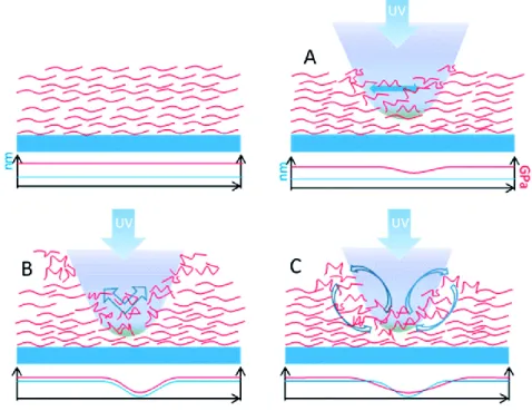
features embossed can be erased by heating the sample above Tg, and by a circular polarized light or an incoherent light source that can also revert the surface to its initial flat profile by a randomization of azobenzenes.66 After the erasing, the azofilms show no evidence of degradation or charring of the polymer films. As discussed previously, despite considerable research, this complex phenomenon is not completely understood yet. Hurduc et al, proposed a new mechanism of SRG formation directly observed the fluid state formation by optical microscopy. They highlighted the importance of polymer chemical structure in the softening/fluidization.80 The SRG formation is based on three different processes that can take place simultaneously: the polymer photo-fluidization in illuminated regions; the mass displacement from illuminated to dark regions and the inverse mass displacement, from dark to illuminated regions (Figure 1.8).
Figure 1.8 The proposed mechanism for SRG formation during laser irradiation, involving at least three processes: A) the polymer photo-fluidization in illuminated regions, B) the mass displacement from illuminated to dark regions and C) the inverse mass displacement from dark to illuminated regions. (Reprinted from Soft Matter 2014, reference 80)
23
1.6.2.2 Regular Surface Reliefs by 1D Gaussian Laser Beam
Interference lithography in Lloyd’s mirror configuration is commonly used to emboss surface relief grating (SRG) on azopolymer films. Furthermore, a single focused laser beam allows for embossing linear pattern on azopolymer surfaces by moving the sample consistently to the light polarization direction.81 A single Gaussian laser beam can induce an azosurface deformation, by aligning the azobenzene groups in the direction perpendicular to the polarization of the incident light.79 In accordance to the observations of polarization-dependent formation of the SRGs, Bian et al. reported a single Gaussian beam-induced deformation on different azopolymer materials.82 It is known that the mass migration process depends on the light polarization, intensity and wavelength.56 In fact, they demonstrated that the photoinduced surface deformation occurs in the direction of the light polarization. In fact, the exposure with a polarization perpendicular to the direction of the light intensity does not produce appreciable surface variation. Furthermore, the presence of an intensity gradient by itself does not lead to surface deformation. The focused beam is able to make a hole in correspondence to the center of the laser spot and the resulting surface deformation is influenced by the polarization and intensity of the laser beam. A dip is formed in the center while the polymer chains moved out from the central region and piled up at the wings where the intensity is small, when the surface deformation is induced by a linearly polarized Gaussian beam focused on an azopolymer film (Figure 1.9 a). In contrast, the polymer surface deformation results completely different when induced by a higher-intensity linearly polarized Gaussian laser beam. In this case, a peak in the surface profile appeared in the center of the exposed spot (Figure 1.9 b). This behavior at higher intensities can be explained by some photochemical reactions in addition to photothermal and photobleacing effects that can occur in polymeric matrix.81 When the surface deformation is induced by a circular polarization Gaussian beam, the polymer moves from the center to the outside of the focused laser spot, thus forming a doughnut-shaped pattern (Figure 1.9 c). A symmetric dip on the surface was formed because of the polarization direction of the optical field sweeping in all radial directions which always causes an intensity gradient.82
Figure 1.9 a) Surface deformation induced by Linear polarization Gaussian beams with low intensity and b) with high intensity. c) Surface deformation induced by circular polarization Gaussian beams with low intensity. (Reprinted from
24
There are few reports on surface deformations that are induced by a single focused laser beam.81, 83
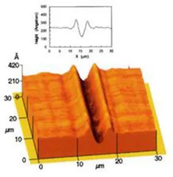
Noga et al. with optical technique produced topographic features of different shapes on the surface by controlling the position of the sample with respect to the focalized laser beam. They analyzed the changes of embossed topographies by tuning the thickness of the polymer layer, the temperature and the wavelength of laser beam.84 A symmetric groove was formed when the surface deformation was induced by a cylindrical Gaussian beam along the direction of the light intensity gradient. The central bottom of the groove corresponds to the position of maximum light intensity (Figure 1.10). In contrast, no appreciable deformation was observed when the laser beam had a polarization perpendicular to the direction of the light intensity gradient.81
Figure 1.10 Surface deformation induced by a one-dimensional Gaussian beam. (Reprinted from Applied Physics
Letters 1998, reference 81)
For all kinds of polarization of Gaussian beam, the polymer migrates in the direction of the polarization of the light from high to low light intensity regions. Effectively, the resultant polymer deformation is strongly dependent on many parameters. Tanabe et al. discussed the effect of the incident light polarization and the position of the laser focus on the deformation pattern.85 In particular, they found that the deformation pattern was strongly dependent on the z- position of the focused laser spot. When the z-position was exactly on the film surface the polymer moved along the polarization direction from the center to the outside of the focused spot, thus producing two side lobes
25
along the polarization direction and a pit at the center (Figure 1.11 a). If the z-position was above the film surface in air, the polymer formed a protrusion coming out towards the center of the laser focus (Figure 1.11 b). The polymer movement was blocked by the substrate and so the protrusion was not formed, when the laser was focused into the glass substrate, (Figure 1.11 c).
Recently, different kind of sources have been used to induce an azopolimer mass migration. Ishitobi et al. presented the first report of two-photon induced plastic surface deformation in azopolymer films.86 In their work, they reported on the deformation induced by a gradient of light intensity depended by the wavelength, polarization direction of the incident laser light and z-position of the focused spot with respect to the plane of the polymer film. In this last case, divergent results respect one-photon absorption has been reported. When the z position of the focus was below the film surface, the polymer always moved from the outside to the center of the focused laser spot along the direction of the polarization of the excitation light and formed a protrusion at the center and two dips, one at each side of the protrusion along the polarization direction (Figure 1.12). However, no deformation was induced due to the intensity of the light spot at the film being not large enough to induce two Figure 1.11 (Left column) Line plots of the surface deformation and (right column) schematics of the relationship between the Z-position of the focus and the film surface at a) Z = +500 nm, b) Z = 0 nm, and c) Z = -500 nm. (Reprinted from
26
photon isomerization and polymer movement, when the distance between the focus and sample surface was larger than 5 μm.
Moreover, it is extremely interesting the possibility¸ independently proposed by the groups of prof. Ambrosio and Netti, to emboss photopatterns on azomaterial with a confocal microscope.87-88 Ambrosio et al. realized different topographies (i.e. trenches and bumps) by changing the mutual orientation of the light polarization direction with respect to the sample scanning direction. In more details, they observed the formation of channels when the sample was moved perpendicularly to the light polarization direction, while they obtained ridges when the sample was directed along the polarization direction.88 In Netti’s group, C. Rianna et al. used the confocal microscope for embossing
patterns in the presence of cells. The mass transport induced by the azobenzene isomerization was activated only inside drawn regions-of-interest (ROIs) by a confocal microscope, scanned by means of galvanometric mirrors. This method allowed to have a great versatility to emboss pattern with Figure 1.12 (Left column) Line plots of the surface deformations and (right column) schematics of the relationship between the Z position of the focus and the film surfaceat a) Z = +2 μm b) Z = -2 μm. (Reprinted from Optics Express
27
different shape (concentric squares, triangles, sphere‐like geometries) realized by simply changing the geometry of the irradiated regions (Figure 1.13).87
1.6.2.3 Randomly‐distributed Surface Reliefs by One‐Beam Irradiation
In 2002, Hubert et al. reported for the first time a spontaneous self-organization of the flat surface of a thin azofilm into ordered hexagonal bumps by a one-beam irradiation. The material creates a diffraction structure in order to optimize the light dissipation.89 Furthermore changing the irradiation conditions, also parallel stripes, or turbulent structures can be generated in azobenzene-based materials (Figure 1.14).
Figure 1.13Different patterns on pDR1m. SEM images of several patterns realized on pDR1m films by using a
confocal microscope, drawing several ROIs and irradiating the sample with 514 nm Argon laser wavelength. A) Concentric squares, B, C) triangles, and D) sphere‐like geometries realized by simply changing the features of the irradiated regions. (Reprinted from Advanced Functional Materials 2016, reference 87)
Figure 1.14AFM images of hexagonal structures for a) vertically, b) horizontally, and c) circularly polarized incident laser beam. (Reprinted from Advanced Materials 2002, reference 89)
28
Several attempts have been carried out to understand the underlying physics that controls these various forms of pattern formation. The dependence of photoactivated pattern formation on both the light’s intensity and polarization has been extensively investigated, but its physical explanation is still incomplete. Galinski and co-workers, for examples, explained the pattern formation entirely based on principle of phase separation in the polymer.90
1.6.3 Directional Photofluidization Lithography (DPL)
An interesting effect can be observed when the mass migration does not interest a flat film but a more complex 2D topography. Coupling the properties of azomaterials with other fabrication techniques allows for the realization of micro/nano structures of different shape and size (e.g., pillars, wives, bars). In particular, the combination of soft lithographic methods and light-induced mass migration leads to topographies tunable after the fabrication. For instance, anisotropic movement of 2D structures under light illumination has provided significant opportunities for the fabrication of complex micro/nanoarchitectures. Main examples include reshaping of funnels, circular or ellipsoidal holes and pillars. This process is known as directional photofluidization lithography (DPL). There are many examples in literature of azopolymer patterns subsequently modified by irradiation.91,92 Kang et al. fabricated a linear azopolymer array by soft lithography and successively photo-reconfigurated it by holographic photofluidization, tuning the polarization of the interference patterns (Figure 1.15).91 In particular, the use of holographic photofluidization in a monolithic evolution of hierarchical SRGs could be useful both for exerting unprecedented control over structural features by adjustment of the polarizations and for modulation height of the SRGs by light irradiation time. Also Lee et al. reported the reconfiguration of line arrays obtained with a single beam irradiation that evolved in ellipsoidal hole array when irradiated perpendicularly to the array by two beam interfering.92
29
To sum up. the coupling of DPL and soft lithography leads to the fabrication of a plethora of 2D arrays. These complex structures could be reshaped by light after their fabrication, allowing for creating of 3D complex structures (e.g., domes, mushrooms, lemons, canoes) from a regular array. The advantage of this technique is the possibility to obtain structures not easily fabricated by conventional methods.93 Lee and co-workers produced for the first time a set of pillars containing-azobenzene using a PDMS negative master.59 The profile of the pillars were reshaped after the fabrication using polarized light by directional photofluidization of azobenzene materials. Under irradiation with a linearly polarized light, azo-materials became fluidized at room temperature and their direction flow was parallel to the light polarization. This behavior led to shape transition from an initial circular pillar shape to ellipsoidal. However, this process was hardly reversible on isolated azopolymer micro-objects, as an excessive photofluidization resulted in a material flow outside the initial volume, created mushroom-like structures.45, 94 In order to avoid that the light irradiation brings
the azopolymer to flow down on a substrate, different approaches have been adopted. Lee and coworkers confined the light-driven mass-migration inside the edge of the posts putting an extra PDMS capping layer on the posts.92-93, 95 Pirani et al. increased the mechanical response to light of Figure 1.15 Monolithic evolution of hierarchical SRGs by holographic photofluidization of azopolymer line arrays: (step 1) fabrication of original azopolymer line arrays by MIMIC using a solvent; (step 2) monolithic evolution of hierarchical SRGs by interference pattern irradiation. The SEM image indicates obtained original azopolymer line array. (Reprinted from Advanced Functional Materials 2011, reference 91)
30
pillars using a polymer blend (polymethylmethacrylate (PMMA) within a PAZO-PMMA mixture), so avoiding the polymer overflow outside the initial volume. This blend formulation allows a reversible and controlled deformation of the micro-pillars by periodically tuning the laser polarization in time reducing also the degradation of the structure morphology over several cycles (Figure 1.16 a-d).96 In this way, it is possible to obtain a reversible process and a back and forth transition from pillar to elongated pillar by alternating LPL and CPL irradiation.96 During this process, many interface properties (shape, phase, and wettability) can be affected. Illuminating the pillar array, Oscurato et al. analyzed how the superficial wetting properties are tuned, elongating the three-dimensional geometry of soft-lithographic imprinted micropillars. They showed the ability of the light-induced pillar reshaping of tuning the wetting anisotropy of the surface in a reversible way (Figure 1.16 e).97 Recently Pirani et al. have showed a directional reversible change of hydrophobicity of pDR1m pillars with a locally anisotropic topography induced by light irradiation. In particular, they obtained a change of contact angle of a water droplet on the structure of roughly 30° due to a precise spatial-temporal control of the light induced deformation of an azopolymer microstructure. Finally, they showed a partially reversibility of the process when the pillar elongation was kept within a roundness larger than about 0.5.98
(e)
Figure 1.16 Exemplary SEM pictures of individual pillars: A) before laser irradiation, B) after a single laser exposure with LPL, C) after two laser exposures with two orthogonal polarizations (restored circular cross section). D) Time-resolved roundness values for pillars during laser irradiation with time-varying polarization state (black dots: roundness of individual pillars, blue circles: mean value over pillars in each frame). E) Light induced superficial asymmetry and directional wetting anisotropy. (Reprinted from Scientific reports 2016, reference 96 and ACS applied materials &
31
As mentioned previously, the initial pillar array is usually fabricated by soft lithography. A more innovative approach uses the photo fluidization properties of azobenzene to fabricate nanostructures and not only for modifying already existing arrays. Choi et al. reported the possibility to obtain directly patterned superficies from micrometer to sub-100 nm range by vertical-directional photofluidization of azobenzene materials. They showed the advantage of obtaining structures into a range which is typically not feasible by soft lithography technique. In particular, they focused on vertical directional movement of azobenzene materials instead on, largely investigated, lateral directional movement of azobenzene materials. Submicrometric structures were fabricated by two-step illumination, first a slantwise- circularly polarized light was directed onto azo material film in contact with patterned elastomeric molds (i.e., PDMS), followed by a perpendicular irradiation. Under illumination, the polymer drifted upward along the cavities of the molds resulting in pattern formation. This light-induced fabrication was defined directional photofluidization imprint lithography (DPIL) and provided also a facile way to fabricate complex hierarchical multiscale structures.99
1.7 Azopolymers as Dynamic CIMs
In the last years, a variety of structures containing azobenzene have been fabricated in order to obtain photo-tunable surfaces able to change their properties when illuminated by light at a certain wavelength. The most common examples of azo-materials are based on amorphous polymeric chains, for instance, poly (disperse orange 3) (PDO 3), and polydisperse red1 methacrylate (pDR1m).95 Their extraordinary ability
in photofluidization leads to additional flexibility in the micro/nanofabrication techniques.95 This tunability
represents another strong advantage for the production of light-responsive materials in different fields such as microfluidics, tissue engineering50 and optoelectronics.100 In this thesis, we have focused on the
advantage of azomaterial properties in biological field, to obtain dynamic scaffolds for in vitro study of cell behavior. Cell attachment, proliferation, migration, differentiation have been usually analyzed in static environment, which led to results sometimes not complete and difficult to interpret.101 Baac et al. were the first to use SRGs imprinted with interference lithography in Lloyd’s mirror configuration on an azopolymer film to culture primary human astrocytes (Has). Cells respond to the underlying pattern and appeared oriented and elongated along the direction of holographically formed SRGs.102 Successively, Hurduc et al. proposed an interesting work in which, highlighted the advantages to use azo materials as support in cell cultures. They introduced a new class of materials with azo-polysiloxanic structures, chemically modifiable due to the presence of the chlorobenzyl groups in the polymeric side-chain.101 This allowed to precisely tune the chemical signals transmitted
32
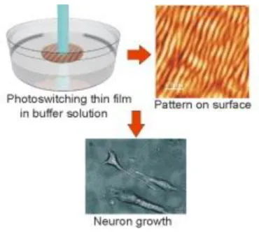
to the cellular membrane with immediate consequences on the cell fate. Berille et al. investigated the effect of writing and erasing pattern on an azopolymer-based platform in the presence of PC12 cells. They proposed a direct inscription of a pattern in the presence of cells, while the sample was immersed in a phosphate buffered saline (PBS). For their investigation, two different azo biocompatible nanopatterns were fabricated, the first with an optical interference pattern and the second by self- organization of azopolymer under single laser beam irradiation (Figure 1.17). Their technique could be used to fabricate on demand platforms for controlling surface topography in real-time and in biocompatible condition.103
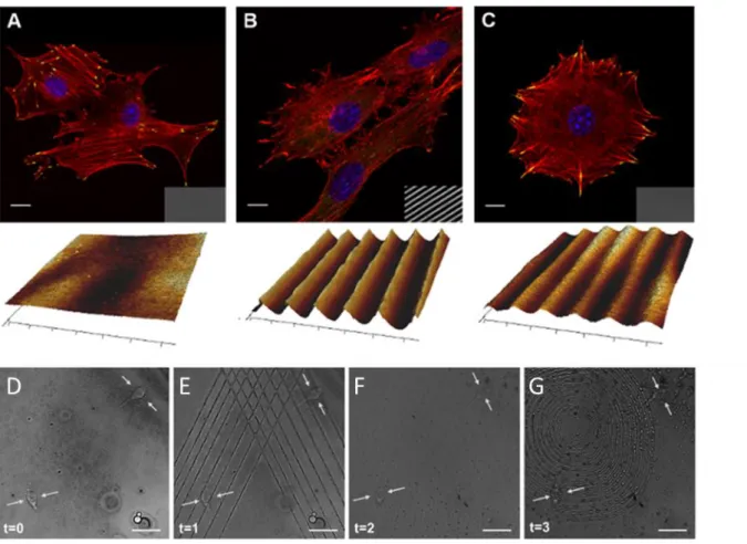
Also our group has mainly focused on using mass migration displacement of azopolymer to write and erase specific patterns in the presence of cells. Rianna et al., showed the possibility to write a linear pattern on an azopolymer thin film in the presence of cells with a confocal microscope, analyzing the cell response in real-time.87 As mentioned earlier, the confocal set-up equipped with a cell incubator allows to emboss different patterns on the same cell-populated azosubstrate in biocompatible conditions to evaluate different cell response simultaneously (Figure 1.18).87
Figure 1.17 Inscription of a pattern on the surface with a laser when the biopolymer thin film is immersed in a buffer solution. (Reprinted from Colloids and Surfaces B: Biointerfaces 2011, reference 103)
33
Recently, also liquid crystalline elastomers (LCEs) are earning more attention as dynamic cell scaffolds. The macroscopic motion of LCP containing- azobenzene upon light illumination suggests that they could be a valid approach for future biological applications. Typically, the use of liquid crystalline polymers as biomaterials have been limited by high temperature required for nematic-to-isotropic transition. Instead, the presence of azobenzene in LCP can drive a transition between liquid crystalline phases with light, avoiding the use of high temperature for cell culture. For example, Jonkheijm et al. analyzed the cell migration on light-induced surface change of LCE in situ.104 Martella et al. explored the biocompatibility of acrylate-based LCN film by testing their ability to promote cell differentiation and maturation for different murine and human cell lines, demonstrating an amazing contribution of LCN films in human induced pluripotent stem cell-derived cardiomyocyte (hiPSC-CM) growth, speeding it up in respect to common substrates.105
Figure 1.18 Confocal images of NIH-3T3 cells cultivated on A) flat pDR1m substrate, B) SRG grating, and C) pattern erased with circularly polarized light. Transmission images of the substrate are reported in the bottom right of each confocal micrograph and AFM scans are shown below them. Confocal images of write/erase/write pattern. NIH-cell on D) flat pDR1m E) triangular inscription embossed with confocal set-up F) erased pattern with incoherent light G) second pattern inscription. (Reprinted from Advanced Functional Materials 2016, reference 87)
34
1.8 The role of Topography in the Regulation of Stem Cells
Adult stem cells such as human mesenchymal stem cells (hMSCs) are multipotent cells that contribute to tissue regeneration.106 In response to a stimulus such as a trauma or disease, hMSCs circulate away from their niche and engraft in mechanically diverse environments to renew bone, cartilage, muscle or fat. Adult stem cells in vivo are found in specific locations of a tissue (niches) that are responsible of different functions such as maintenance of stem cell populations, control of their proliferation and differentiation into multiple cellular lineages.85 The ECM in these microenvironments is a complex network that presents to cells both nano- and micro-topographic features. They have a direct impact on cell behavior and cells are able to sense surface patterns ranging from 10 nm to 100 μm.37, 107 Smart
surfaces have been fabricated with controlled stiffness, different micro-nanoscale topographies and chemistries to recapitulate the topographic landscape of native cellular niche. The physical properties of biomaterials have been shown to directly influence stem cell fate acting alone or in combination with chemical cues.45,108,109 Various signaling pathways have been implicated in the regulation of hMSCs differentiation; however, complexities of pathway interactions are still under debate. Numerous works reported topographically patterned arrays including posts, pits, ridges, grooves, or gratings with different geometries and sizes to control the stimuli on stem cells. As mentioned above, this mechanosensitive interaction initiates a cascade of signaling pathways within the cell leading to inner cytoskeleton rearrangements. In particular, ridges/grooves are deeply investigated resembling the native collagen structures of ECM. As example, Wagner and coworker generated micro- and nano-patterns in polyimide with ridge ranging from 2 μm to 15 μm and analyzed the differentiation of MSCs towards specific lineages. They reported that 15 μm ridges increased adipogenic differentiation whereas 2 μm ridges enhanced osteogenic differentiation. Notably, the comparative analysis indicated that the size of the ridges is more important than the size of the grooves to support lineage specific differentiation of MSCs.37 In particular, hMSCs differentiated into osteoblasts when allowed to spread and flatten, whereas restricting the surface area upon which to grow promoted adipogenic differentiation of hMSCs.108 While nano-patterns with a periodicity of 650 nm increased differentiation towards both osteogenic and adipogenic lineages. Concluding that grooved surfaces did not induce differentiation per se, but by supporting the differentiation processes initiated by induction media. Instead, Watari et al. demonstrated that a specific size scale of topographic cues (400 nm pitch) promote osteogenic differentiation with or without osteogenic agents. They used topographically-patterned substrates containing anisotropically ordered ridges and grooves to investigate the effects of topographic cues on mesenchymal stem cell morphology. They attributed
35
their results to a greater average cell area of hMSCs cultured on 400 nm pitch instead of 4000 nm to promote osteogenic differentiation.25 Initially, hMSCs were believed to be restricted to mesenchymal
lineages. Successively, the pioneering study of Woodbury et al.110 demonstrated the differentiation
of rat and human bone marrow stromal cells into neurons, and so many other groups investigated neuronal differentiation of hMSCs. The mechanism responsible for the transdifferentiation of mesenchymal stem cells to neurons can be induced by neuronal induction medium and/or cell contact with neurons, but it is not well understood yet. Also, Genetos and co-workers differed from previous studies, that induced only osteogenic markers on topographic ridges and grooves, instead, showed a number of neuronal markers on pattern with 700 nm pitch.111 Furthermore, micro- and nanostructured surfaces, in particular grooves, have been also used to study the role of mechanical cues in cell self-renewal or reprogramming.107 Strikingly, microsized alignment “wrinkles” were observed to increase significantly the efficiency of reprogramming of mouse fibroblasts.112 Numerous works have reported the effect of surface topography in stem cell differentiation. Furthermore, multiple combinations of materials with several physical characteristics were used to assess the role of topographic features in cell fate. In fact, a proper utilization of stem cells for clinical applications requires an integrated understanding of multiple signal inputs that control maintenance of stemless, proliferation, commitment and differentiation.