Alma Mater Studiorum
· Universit`a di Bologna
Scuola di Scienze Corso di Laurea in Fisica
Studies on ToF-PET using Cherenkov
radiation
Relatore:
Prof. Tiziano Rovelli
Presentata da:
Francesco La Rosa
Sessione II
Sommario
La tomografia ad emissione di positroni (PET) è una tecnica di imaging di medicina nucleare, utilizzata oggi diffusamente in ambito clinico. Essa fornisce immagini e informazioni fisiologiche dei processi funzionali all’interno del corpo. La PET si basa sulla rilevazione di fotoni di annichilazione prodotti in seguito al decadimento di un radio farmaco iniettato nel paziente. I rilevatori convenzionali sono costituiti da un materiale scintillatore accoppiato ad un fotomoltiplicatore, solitamente un PMT o SiPM.
Uno sviluppo della PET è la Time of Flight PET (ToF PET), attualmente già in commercio ed utilizzata con prestazioni eccellenti. Un’ulteriore modifica, che potenzialmente permetterebbe di ottenere una migliore risoluzione temporale, è la ToF PET basata sulla rilevazione di fotoni tramite radiazione Cherenkov, invece che luce di scintillazione. Questo lavoro di tesi è incentrato dunque su questa tecnica specifica. Si illustra una rassegna di pubblicazioni scientifiche degli ultimi anni riguardo ad essa con i relativi risultati ottenuti e i possibili sviluppi futuri. Infine si propone un approfondimento personale, nel quale, tramite un programma scritto in ROOT, si è realizzata una geometria di un sistema di rilevazione ToF PET. Esso prevede la rilevazione dei fotoni di annichilazione tramite un radiatore Cherenkov accoppiato ad un SiPM. In futuro questo potrà essere implementato e utilizzato per simulare il processo fisico della PET, verificando la validità e le prestazioni del sistema così sviluppato.
Abstract
Positron emission tomography (PET) is an imaging technique of nuclear medicine, widely used today in the clinical field. It provides images and physiological
information about functional processes inside the body. PET is based on the detection of annihilation photons, generated as a result of the decay of the
radiopharmaceutical injected into the patient. The conventional detectors are made of a scintillator material coupled to a photodetector, usually a PMT or SiPM.
An improvement of PET is Time of Flight PET (ToF PET), currently on the market and used with excellent performances. A further development, which potentially would allow to obtain a better timing resolution, is the ToF PET which relies on the detection of photons by Cherenkov radiation, instead of scintillation light.
This work focuses on this specific technique. It is presented a review of scientific publications of the last years about it, with the results obtained so far and the possible future developments. Finally it is shown a personal work, where through a program written in ROOT, a geometry of a ToF PET detection system is realized. The system is based on the detection of annihilation photons with a Cherenkov radiator coupled to a SiPM. In the future this could be implemented and used to simulate the physical process of PET, checking the efficiency and performance of the system so
Contents
Contents ... 5 Introduction ... 6 Chapter 1: Positron emission tomography ... 8 1.1 Radioactive decay ... 9 1.2 Radiopharmaceuticals ... 10 1.3 Scintillator materials ... 12 1.4 Photomultipliers tubes (PMTs) ... 14 1.5 Silicon photomultipliers (SiPMs) ... 18 1.6 PET scanner using PMTs ... 20 1.7 Data acquisition ... 20 1.8 PET scanner performance ... 22 1.9 Time of Flight PET ... 23 Chapter 2: ToF-PET using Cherenkov radiation ... 27 2.1 Cherenkov radiation ... 27 2.2 Photons interaction processes with matter ... 28 2.3 Cherenkov radiators ... 30 2.4 Photons production and detection ... 31 2.5 Scientific publications on the topic ... 32 2.6 Personal work and possible development ... 34 Conclusion ... 38 Bibliography ... 39 Appendix A: A ROOT program of a single detector PET geometry ... 43
Introduction
Positron emission tomography (PET) is a non-invasive, diagnostic, medical technique widely used today to analyse functional processes in the body. It has many applications in the fields of oncology, neurology and cardiology, but it is also studied for uses in other areas.
PET detects the concentration of a radiopharmaceutical injected into the patient and creates a 2D or 3D image, which gives information about the physiology and anatomy of the organs or tissues studied. In the body of the patient the
radiopharmaceutical undergoes a β+ decay and therefore a positron is emitted. The positron loses some energy, travelling a very short distance, until it annihilates with an electron of the tissue. From this process two 511 keV annihilation gamma rays are produced back to back. The aim of the photodetectors of the PET system is to detect this pair of gammas and reconstruct the line where the annihilation process took place. For this reason, multiple rings of photodetectors are placed all around the patient. An event is recorded only when two gammas are detected almost
simultaneously by opposite detectors. A time delay often means that the gammas have been scattered, loosing part of their energy, or belong to different annihilation processes.
In the conventional PET systems the detectors are made of a scintillator material and a photomultiplier. Travelling through the scintillator, the annihilation gammas generate light photons, which are detected by the photomultiplier. An electric pulse, proportional to the intensity of the scintillation light, is then produced as output signal. From this signal the images showing the concentration of the
radiopharmaceutical in the body can be reconstructed.
Time of Flight (ToF) PET is a possible technique, currently in use, to improve the quality of the images. It provides an additional measurement of the arrival time of the annihilation gammas at the opposite photodetectors. This time difference gives, with some uncertainty, the location of the annihilation site along the line between the two detectors. In this way, a better signal-to-noise ratio can be achieve, as the
statistical error is reduced. Therefore the quality of the reconstructed images is improved.
The performance of a ToF PET system depends mainly on how well the time
difference can be determined and so on the time resolution of the detector. This has a contribution from the time constant of the scintillator and another one from the photomultiplier. Different scintillator materials and new types of photodetectors are constantly studied in order to minimize this sum.
The possible improvement of ToF PET analysed in this work is based on the detection of Cherenkov radiation, instead of scintillation light. Cherenkov radiation is produced promptly in a medium when charged particles travel at a speed than exceeds the speed of light in that medium. These charged particles (electrons) are produced in this case by the interaction of the 511 keV annihilation photons with matter, through the photoelectric or Compton effect. Therefore, instead of the
scintillator material, a Cherenkov radiator will be present in the detector, whereas the photodetector keeps the same function. The timing resolution of such a detector could be considerably higher, due to the fact that the Cherenkov photons are
produced promptly and not after a time constant, as for the scintillation light. In addition to this, new photodetectors with improved operating characteristics are constantly being developed, so this also helps reducing the time uncertainty. ToF PET detecting Cherenkov radiation is a very promising technique and considerable benefits could be obtained in the reconstructed images in the near future.
In the first chapter of this work, the physical principles of PET and the most used radiopharmaceuticals are outlined. Then two type of photomultipliers, the PMTs and the SiPMs, and all their operating characteristics are analysed. ToF PET is then described, pointing out its advantages compared to a conventional PET system. In the second chapter a general characterization of Cherenkov radiation is given and then the main interaction processes of photons with matter are explained. It follows a detailed analysis of Cherenkov radiators and of this peculiar Cherenkov ToF PET method. Many scientific publications of the last years on the topic are taken into consideration and compared to show the best results that have been obtained so far. Finally a personal work on a ToF PET geometry, based on the detection of
Chapter 1
Positron emission tomography
Positron emission tomography is a radiotracer imaging technique used to observe and study biological processes in the body. It produces a two or three-dimensional image with useful diagnostic information. Unlike other radiotracer technique, PET analyses biochemical and physiological processes in vivo and this, compared to in vitro studies, gives a better comprehension of the phenomena as a whole.
In a PET study a radiopharmaceutical is injected into the patient and its
concentration in the body is detected. The radiopharmaceuticals are radioactive preparations, labeled with a radionuclide, and their choice depends on the ability to accumulate in the tissue of interest. The tracer concentration is then observed and studied, as it gives information about, for example, possible cancer metastasis.
Figure 1.1: image of a typical PET facility [1].
Once the radiotracer is injected, it decays in a short time, emitting a positron (beta decay). This positron will travel for a very short distance in the tissue, loosing kinetic energy principally by Coulomb interaction, until it annihilates with an electron. The
annihilation produces a pair of gamma rays back-to-back, which means that they travel to almost opposite directions. Each gamma ray has an approximate energy of 511 keV, as this is the electron (and positron) rest mass. This energy allows the majority of gamma rays to travel through the tissues without being absorbed or scattered and reach the detectors with still 511 keV. The patient, in fact, is
surrounded by a ring of gamma rays detectors, made usually of scintillator crystals and photomultipliers. If two gamma rays are detected on the opposite sides of the scanner almost simultaneously, then this is registered as an event. The line connecting the two gamma detectors is called the line of response (LOR) and it is along that line that the annihilation takes place. Once many of these events are obtained, a two or three-dimensional image of the radiopharmaceutical concentration in the body is constructed, thanks to computer algorithms. An image of a PET
facility currently located in hospitals is shown in Figure 1.1.
This chapter starts with a general description of the radioactive decay and in particular of the β+ decay. Then the radiopharmaceuticals used in PET, which
undergo β+ decay, are analyzed and their applications described. Then, a general characterization of PET scintillators and photodetectors (PMTs and SiPMs) is given, with a detailed explanation of how the data is acquired and the image reconstructed. The main PET operating characteristics are also examined. Finally a description of the time-of-flight PET (ToF PET), a relatively recent, but very relevant, PET development, is given.
1.1 Radioactive decay
Decay is the spontaneous transition of one particle or nucleus to two or more objects. Decays usually occur because the sum of the masses of the final objects is smaller than the mass of the initial one. Therefore a less energetic and more stable state is reached through the decay. A radioactive decay occurs when an unstable nucleus loses energy emitting radiation, which includes alfa particle, beta particle, gamma rays and conversion electrons.
The decay process follows an exponential law: defining the decay rate λ and the initial number of nuclei N0, the number of nuclei remaining after a time t is
expressed by:
N t = N!e!!! (1.1)
Another characteristic constant of the decaying process is the half-life t1/2, which
represents the time it takes for the initial quantity to become reduced by half. This can be expressed in terms of the decay rate λ as:
𝑡!/!= ln (2)
The positron emitting radionuclides most used for PET imaging have a half-life that is in the order of tens of minutes.
The β+ decay is a type of radioactive decay in which a proton decays into a neutron, releasing a positron and a neutrino. The positron emitted in the decay is called the beta particle. There is also the β- decay, where a neutron decays into a proton; an
electron and an antineutrino are released in this process.
In the PET the radionuclide undergoes a β+ decay, which can be seen as:
𝑝 → 𝑣 + 𝑒!+ 𝑛 (1.3)
and allows the atom to optimize its ratio of protons to neutrons in the nucleus.
The positron emitted will travel for a very short distance, which depends on its initial energy and on the material characteristics. Usually these positron ranges are less than a millimetre. Once the positron has lost almost all its kinetic energy, annihilation with an electron takes place and two gamma rays are produced, with an angle between them very close to 180°.
1.2 Radiopharmaceuticals
Proton-rich isotopes, which may undergo β+ decay, are needed to synthetize the
radiopharmaceuticals. These radionuclides typically used in PET are made
artificially through nuclear reactions, where a charged particle beam is accelerated in a cyclotron and then the beam particles, once they have the right energy, collide on a target to get the desired nuclide.
The cyclotron is the first circular particle accelerator, realized by Ernest O. Lawrence in 1932. The particles move in a spiral trajectory, held by a static magnetic field and accelerated by an electric one.
Usually in the biomedicine sector cyclotrons accelerate protons or deuterons beams in order to make them collide with a target and hence produce positron-emitting radionuclides, which are used, for example, in PET.
Once the radionuclides are obtained, they are incorporated into a larger pharmaceutical-active molecule and through a chemical reaction the final
radiopharmaceutical is produced. The most used radiopharmaceutical in PET is 18 F-Fluorodeoxyglucose, an analogue of glucose used in cellular metabolism. A higher concentration of the tracer indicates tissue metabolic activity and in this case it corresponds to glucose uptake. One of the metabolic changes shown by tumor cells is an increase in glucose metabolism and dependence and so this is a widely used method to explore the location of possible cancer metastasis. About the 90% of the PET scan are currently carried out using the 18F and have the aim to detect and diagnose possible cancers, making oncology the largest clinical area of PET. 18F has a half-life of 110 minutes, one of the longest between the radiopharmaceuticals used
for the PET. For this reason all the radiopharmaceuticals must be produced near the PET scan site and often hospitals have their own cyclotron to obtain the
radionuclides.
Isotope Half-life Radiopharmaceutical Uses
11C 20.4 minutes Methionine Visualize primary brain tumors and recurrence/progression after therapy
Flumazenil Neuroreceptor characterization Raclopride Detection of various neurological and
psychiatric disorders (Parkinson’s disease, schizophrenia, etc.) Choline Imaging of prostate cancer
13N 10 minutes Ammonia Myocardial perfusion imaging
15O 2 minutes Water Studies of myocardial and cerebral
perfusion
Butanol Blood flow measurement in brain and other organs
18F 110 minutes Fluorodeoxyglucose Imaging of the metabolism in the brain and heart, detection of epilepsy and
tumors
Sodium Fluoride Bone imaging
Fluorothymidine In vivo studies of cellular proliferation in human tumors
82Rb 75 seconds Rubidium Chloride Myocardial perfusion imaging
Table 1.1: The most common radiopharmaceuticals in PET therapy, with their uses, their isotopes and half-life times [2], [3], [4], [5].
1.3 Scintillator materials
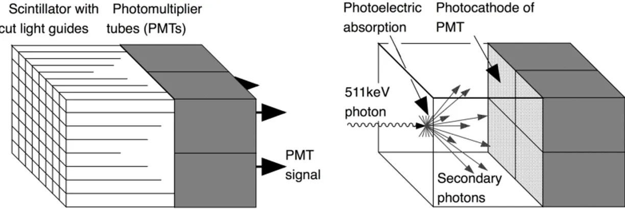
The conventional scanning devices used for PET are made of a scintillator and a photodetector. The aim of photo detection is to measure the total energy deposited by the incident gamma ray, as it interacts with the scintillator, and its arrival time with good precision. Scintillators are materials that release ten of thousand of visible or UV light photons during the interaction with the high-energy annihilation gamma rays. All around the sides of the scintillator there is a reflecting material, so that almost all the photons reach the photodetector, which is coupled to the further face of the scintillator (see Figure 1.2). The photodetector creates electric signals
proportional to the intensity of the scintillator light pulse. An event is then recorded when two opposite detectors release signals in a very small time window, meaning that the two photons could belong to the same annihilation process. In this work, two types of photodetector used in PET will be analysed, the photomultiplier tube (PMT) and the silicon photomultiplier (SiPM).
Scintillators are materials that show scintillation when interacting with ionizing radiation. The incident gamma rays, for example, release their energy to one or more electrons of the scintillator, that become excited and then return to the ground state emitting scintillation light.
Scintillators are characterized by some important properties of the material. First of all, the stopping power, which is the inverse of the mean distance travelled by a 511 keV photon in the material. This length depends on the density and on the atomic number of the material. The higher the stopping power, the lower the
absorption length, which means that shorter and cheaper crystals can be used. On the other side, fixing the size of the crystal, a higher stopping power yields more
interactions and a better efficiency to detect the same number of 511 keV photons [6].
Considering a gamma radiation with a certain energy passing through an absorber material, a related parameter of the material is the linear attenuation coefficient. It describes the effects of the Compton, photoelectric and pair production processes and it is defined as the percentage of photons absorbed per unit length. It is measured in cm-1. It strongly depends on the energy of the incident beam and it increases with the atomic number and density of the absorber. Therefore the stopping power is directly proportional to the linear attenuation coefficient.
Another fundamental quantity is the decay constant of the scintillator, representing the time that the scintillation light lasts in the crystal. It has to be short for good coincident counting and high photon rates. If the decay constant is very short it also allows time-of-flight measurements (see Section 1.9).
Figure 1.2: schematic description of a block detector. The scintillator and the photodetector (PMT in this case) are shown [6].
A good energy resolution is also desirable. This allows the detector to find and discard the photons which have Compton scattered (and lost energy) in the tissue. The energy resolution is expressed in percentage and it depends on the crystal inhomogeneities and on another property of the scintillator, the light output. The light output describes the number of scintillation photons produced per unit of energy by the incident gamma rays. Large light outputs are favourable, because that means better spatial and energy resolution.
Table 1.2 shows the most common scintillator materials and the values of several of their characteristics.
NaI (Tl) is a broadly used scintillator material and its characteristics are considered as reference values, although it is not used in PET detectors today due to its low stopping power (very low density and linear attenuation coefficient). However it is very useful for γ-rays detection thanks to the high light output and good energy resolution. NaI (Tl) has applications in nuclear medicine and in particular it is used for the planar or single photon emission computed tomography (SPECT).
BGO has been in the past years the most used scintillator in PET due to its extremely high stopping power, i.e., high density and attenuation coefficient for 511 keV. Its drawbacks are the long scintillation decay time and low light output, which limit the count rate and energy resolution. Recently LSO, GSO and other materials have been studied and used more by the manufactures of PET systems.
The cerium-doped LSO has been recently developed, as a scintillator for PET, and it happens to be better than the previous ones due to the high stopping power, short decay time and high light output.
BaF2 crystals have the shortest scintillation decay time (0.6 ns) and for this reason are
used for time-of-flight PET (Section 1.9), but have some disadvantages as the low stopping power and light output.
The GSO detectors have overall very good properties and are currently used in PET applications. Their crystals are very fragile, but if treated with good care they can be divided into smaller crystals, improving the spatial resolution.
LaBr3 has a low stopping power, but its extraordinary light output and low
scintillation decay constant make it one the crystals the manufactures are working on for PET technology. In 2010 a group of researchers achieved a really promising
coincidence timing resolution of about 100 ps, for a ToF PET system, with a LaBr3
scintillator coupled to a SiPM photodetector[7]. Table 1.2: Some materials used as scintillators and their main properties [3], [8], [9], [10]. 1.4 Photomultipliers tubes (PMTs)
The photomultiplier tube is a vacuum tube containing mainly an input optical window, a photocathode, several dynodes and an anode (see Figure 1.3). It is responsible for detecting the light pulse created by the scintillator and generating electric signals, as said before. The photons pass through the window and once they strike the photocathode, electrons are generated by photoelectric effect. These electrons are then collimated by a focusing system and accelerated with an electric field towards the first dynode. There are usually about ten dynodes in the photomultiplier, with a 100 V increment between each of them; they make up the electron multiplier section. In fact, when the electrons strike a dynode, several so-called secondary electrons are emitted and these are all accelerated by the voltage difference toward the next dynode. After the last dynode, the electrons are attracted
towards the anode, which generates the output electric signals [11]. This pulse reaches first a pre-amplifier, it is then amplified and finally it can be stored and analysed.
Scintillator
materials Effective atomic number Density (g/cm3) Scintillation decay constant (ns) Light output (per keV) Linear attenuation coefficient of 511 keV (cm-1) Energy resolution (% at 511 keV) NaI (Tl) 51 3.67 250 38 0.34 7.8 Bi4Ge3O12 (BGO) 74 7.13 300 6 0.96 10 Lu2SiO5 (Ce) (LSO) 66 7.40 40 29 0.87 10.1 BaF2 54 4.89 0.6 2 0.44 11.4 Gd2SiO5 (Ce) (GSO) 59 6.71 50 10 0.67 9.5 LaBr3 46.9 5.3 5 61 0.47 5.3
Figure 1.3: A schematic PMT with all its major components labelled [3].
An important operating characteristic of the photocathode is the quantum efficiency (QE), defined as follows:
𝑄𝐸 =𝑁𝑢𝑚𝑏𝑒𝑟 𝑜𝑓 𝑝ℎ𝑜𝑡𝑜𝑒𝑙𝑒𝑐𝑡𝑟𝑜𝑛𝑠
𝑁𝑢𝑚𝑏𝑒𝑟 𝑜𝑓 𝑝ℎ𝑜𝑡𝑜𝑛𝑠 × 100 % (1.4) It expresses the probability for the photocathode to produce a photoelectron per incident photon. Figure 1.4 shows the QE for different photocathode materials and the emission intensity of various scintillators in relation to the wavelength. Another property is the radiant sensitivity (S), which is defined as the ratio between photoelectric current from the photocathode and the incident radiant power at a certain wavelength:
𝑆 = 𝑃ℎ𝑜𝑡𝑜𝑒𝑙𝑒𝑐𝑡𝑟𝑖𝑐 𝑐𝑢𝑟𝑟𝑒𝑛𝑡 𝑅𝑎𝑑𝑖𝑎𝑛𝑡 𝑝𝑜𝑤𝑒𝑟 𝑜𝑓 𝑙𝑖𝑔ℎ𝑡
𝐴
Figure 1.4: Above it is shown the QE for some photocathode materials and below the emission intensity (%) for some scintillators [12].
The most used material for the input window is the borosilicate glass, which
transmits light well until an energy corresponding to a wavelength of about 300 nm. This is the upper energy limit (low wavelength) for the photons that can be detected by the photocathode. The low energy limit depends on the material of the
photocathode. In fact, only the photons with energy higher than the work function of the photocathode material can be detected. Bialkali (Sb-Rb-Cs, Sb-K-Cs), is the most used one and it is sensitive to photons with a wavelength up to 700 nm.
Following the path of the photoelectrons, it is noticed that not all the ones emitted by the photocathode can be multiplied by the dynodes. The fraction that is multiplied is called the collection efficiency (α) and it is important in the definition of the total photon detection efficiency (PDE), expressed as follows:
where 𝛼 is usually around 80% [4]. Modern photomultipliers can reach a PDE of about 40% [11].
Another important parameter of the electron multiplier section is the secondary emission factor (δ), which represents the average number of secondary electrons emitted by the dynodes per incident electron. It is defined as follows:
δ = A × 𝐸! (1.7)
where A is a constant, E is the voltage difference between the last two dynodes and 𝛼 is a factor which depends on the geometry and on the dynode material.
Multiplying δ by the number of dynodes n in the photomultiplier tube, the total gain G can be obtained:
𝐺 = δ! ≈ 10!− 10!" (1.8)
Usually the total gain G of the photomultiplier tube is in the order of 106-107. Therefore PMTs produce a strong and measurable electrical signal.
The time resolution is one of the more important operating characteristics of the PMT. The aim is to have the best time resolution and therefore reduce the delay from the moment the photons hit the photocathode until the electrical signal is produced. The generation time of the photocathode has to be considered, but the main delay is due to the variation of the travel time of the photons inside the tube. It is found that this time is inversely proportional to the number of photoelectrons generated. Thus, the scintillating crystal light output and the PDE have to be maximized in order to reduce the time resolution of the detector. The time resolution of PMTs used in PET is typically in the order of several hundreds of picoseconds.
Recently also microchannel plate PMTs have been tested as photodetectors for ToF PET systems. Microchannel plate PMTs (MCP PMTs) are made of an input window, a photocathode, an MCP and an anode. There is not the usual vacuum tube. A
microchannel plate is a two dimensions array composed of a huge number of glass capillaries, also called channels. They are all connected in parallel and together have the shape of a disk. The diameter of each channel measures between 6 and 20 microns and they are all independent electron multipliers. Primary electrons hit the wall of the channel and secondary electrons are produced and accelerated by an electric field toward the other end of the channel. Compared to conventional PMTs, MCP PMTs have the advantages of a high gain, a really compact size and a fast time response.
1.5 Silicon photomultipliers (SiPMs)
Historically photomultiplier tubes have been the only detector used in PET, but recently due to its bulky size, limited quantum efficiency and highly costs, new photodetectors have been studied [13]. The most interesting one for PET is surely the SiPM, silicon photomultiplier. The SiPM are based upon the APD (avalanche
photodiodes), small silicon devices, very similar to photomultipliers from a functional point of view. APDs are mainly made of a p-n junction, containing a positively doped p region and a negatively doped n region on the two sides of a depletion layer [14]. The incident photons, coming from the scintillator, enter the photodiode and reach the depletion layer, where they are absorbed and electron-hole pairs are generated. This happens in the case that the light energy is higher than the band gap energy and, since the wavelengths in inversely proportional to the energy, the APD is then sensitive only to light wavelength shorter than a certain value, usually around 1100 nm. A bias voltage is then applied to the p-n junction and so a strong electric field is generated, causing the electrons and holes to move to the p and n doped region respectively. They are accelerated quickly enough to produce further electron-hole pairs by impact ionization, producing what it is called the avalanche effect. Eventually they reach the cathode and the anode and a current flows. Therefore the APD, as the photomultiplier, has an internal gain, proportional to amount of incident scintillation light. APDs have a QE that can reach about 90%, very high compared to the one of the PMTs, and have also the advantage that they are not sensitive to magnetic fields. Their two main drawbacks are the low gain (102
-103, compared to 106-1010 of PMTs) and the modest timing resolution [14].
If the APDs operate with a reverse bias-voltage, well above the breakdown voltage, they are said to be in Geiger-mode. In this case a single photon creates a significant avalanche of electrons and the gain becomes virtually infinite. However this is not very useful for PET because the output pulse in independent of the number of photons striking the detector.
Silicon multipliers are made of an array of APDs cells, operating in Geiger-mode, all connected in parallel and on a common silicon substrate. Usually each cell has a quenching resistor of several hundreds kOhm in series, in order to prevent that the large current destroys the diode; this is called passive quenching. After the avalanche process, the current flows through the resistor and a characteristic amount of time, called recovery time, is needed for the cell to restore the reverse bias voltage above breakdown. The cells have typical dimension between 20 and 100 micrometres and are separated from each other with some insulating material strips. Counting the number of activated cells it is then possible to deduce the number of incident photons, assuming that on average each cell is hit by a single photon. The output signal is proportional to the number of activated cells and it is read through aluminium strips.
Figure 1.5: picture of a SiPM made of 24x24 small APDs. The side of the square measures 1 mm [15].
As for the PMTs, an important operating characteristic is the photon detection efficiency (PDE), which depends on the quantum efficiency (QE) and on other factors. The main one is the effective area that expresses the ratio between the
sensitive area of the SiPM and the total area; the separation of the cells requires some dead space. Another parameter of the SiPM is the dark count rate, which is defined as the average rate of registered photons, when there is not any incident light. It results to be fundamental in the image reconstruction process and so it has to be as low as possible.
The advantages of the SiPM are its very high gain (about 106), since it is made of Geiger-mode APDs, and its small dimensions. Furthermore it is compatible with magnetic fields (suitable for PET/MR studies) and has a low sensitivity against temperature [14].
Currently the two main SiPMs manufacturers are SensL Technology and Hamamatsu Photonics. In Italy there is the FBK based in Trento, which collaborates with INFN.
1.6 PET scanner using PMTs
The PET scanner is made of several rings composed of block detectors. A block detector is how the scintillators and photomultiplier tubes are arranged in order to detect the photons with the highest resolution. The scintillation crystals are cut in small pieces and then each piece is segmented by cuts and coupled to usually four photomultipliers tubes, as it can be seen in Figure 1.6. The location of the incident photon is found analysing the fractional electrical pulse generated from each PMT. Many studies on the optimization of the detector geometry and its relation with the timing resolution of the system are currently underway [16].
Figure 1.6: a block detector [8].
1.7 Data acquisition
In PET data acquisition an event is recorded when two 511 keV annihilation photons are detected within a certain time window by two opposite photodetectors.
Somewhere on the straight line connecting the two detectors (LOR) is where the annihilation event is supposed to have taken place. However there are many reasons that can cause a delay of the photon detection time. If the annihilation event happens to be closer to one detector, then considering that photons travel at the speed of light, this detector will receive the photon a few nanoseconds before the other. A more important cause of temporal mismatch is, though, the timing resolution of the detector and the consequent delay.
The coincident events that are recorded are called prompts and have to be carefully analysed. They are divided into true, random, scattered and multiple coincidences.
As it can be see in Figure 1.7true coincidence is the only case where the two photons detected belong to the same annihilation event. Random coincidence occurs when two unrelated photons are detected in the same time windows. Scattered coincidence happens when the annihilation photons undergo Compton scattering in the tissues, changing their direction without loosing much energy. Finally multiple coincidence occurs when more than two photons are detected by different detectors within the same time windows and so their LOR cannot be found.
In order to acquire a coincidence event, first of all the position of the detectors is determined. Then the pulse of the photons detected is verified to be compatible with a 511 keV energy and finally the position of the LOR is stored in terms of polar coordinates.
To estimate the position of the annihilation photon incident on the scintillator crystal and then the LOR, an algorithm is used which analyses the electrical pulses produced by each one of the four photomultiplier tubes of the block detector.
The data of the coincident events is recorded in the form of a 2-D histogram called a sinogram. In the sinogram each LOR is stored with its distance from the centre of the scanner rings r and the angle of orientation ϕ. A diagram is elaborated with the distance r on the x axis and the angle ϕ on the y axis and where each LOR is
represented by a particular pixel. When the acquisition is completed, the total counts of each pixel correspond to the number of coincidence event recorded on a specific LOR. From all the data of the sinogram an image in the x-y space is then
reconstructed thanks to mathematical algorithms. The most basic algorithm is called simple backprojection (SBP), whereas more complicated ones involve Fourier transformations [3][17].
1.8 PET scanner performance
The spatial resolution of a PET system is limited by the physics of the β+ decay and
by the method and devices used to detect the annihilation photons. Therefore the spatial resolution is determined considering many factors.
Analysing a ring scanner made of many detectors, the maximum intrinsic spatial resolution Ri is given by the half side size d/2 of a single detector. For this reason
small crystals are preferable, but they may be very expensive and not easy to manufacture.
Once the positron is emitted from the β+ decay it travels for a little bit in the tissue, loosing its energy, before it annihilates with an electron. The annihilation site is then slightly different for the β+ emission point and this distance is called positron range. The positron range is directly proportional to the positron energy and it must be considered in the reconstruction of the true positron emission position. This error Rp
is assumed to be the full width at half maximum (FWHM) of the positron distribution and for 18F is determined to be about 2 mm.
Another factor, which degrades the spatial resolution, is the noncolinearity. In fact, the two annihilation photons are not always emitted at exactly 180° from each other, but there is difference from perfect colinearity and the FWHM of this distribution is about 0.5°. The error associated with the noncolinearity is found as follows [17]:
R! = 0.0022 D (1.9)
where D is detector ring diameter in cm. Considering a diameter of 1 m, R!turns out to be 2.2 mm.
A further error Kr, which accounts for additional degradation due to the
reconstruction method used, is considered. Finally, in the case that block detectors are used, a slight error Rl is taken into consideration due to the localisation process of
the detector; this depends mainly on the detector material.
Combining all these contributions the total spatial resolution of a PET scanner can be found as follows [17]:
𝑅! = 𝐾! × 𝑅!!+ 𝑅!!+ 𝑅!!+ 𝑅!! (1.10)
Another important characteristic of the PET system is the sensitivity, defined as the ratio between the total number of annihilation photons pair emitted by the source and the number of the ones detected:
𝜂 = !!"#
!!" = 𝜀
! 𝑔
!"# 𝑇!"#$ (1.11)
Here 𝜀 represents the efficiency of each photodetector, 𝑔!"# is the geometry
efficiency of the system and 𝑇!"#$ the fraction of gamma rays not attenuated by the tissues. The 𝜀 is squared, as the total sensitivity depends on the efficiency of each single and opposite detector. The sensibility is expressed in counts per second per
microcurie and it is usually a specific characteristic of the PET system told by the manufactures.
Furthermore another important specification of a PET system is the signal-to-noise ratio (SNR), which is expressed in the following equation:
𝑆𝑁𝑅 = 𝑘 𝑛!"## !
!
! 𝑁!"!#$ !
! (1.12)
Here 𝑛!"## is the total number of pixels of the reconstructed image, 𝑁!"!#$ the
average number of annihilation processes per pixel and k is a factor depending on the reconstruction process. In the next paragraph, which is about time-of-flight PET, the importance of a good SNR is analysed.
1.9 Time of Flight PET
The ToF PET is claimed to be the method through which is currently achieved the highest sensitivity and spatial resolution for a full body PET in hospitals. It has been studied from the early days of PET, but only the recent developments of fast
scintillators and new detector materials have allowed great improvements and the commercialization of the first ToF PET systems.
In ToF PET, when two annihilation photons are detected, the difference in their arrival time is recorded. This allows to localize on the LOR the annihilation site or at least to obtain its probability distribution (see Figure 1.8). An ideal ToF PET would give with certainty the location of the annihilation site along the LOR.
The time difference between the detection of the two photons, Δt, is correlated to the distance, Δx, of the annihilation site from the middle point of the LOR between the two detectors, as follows:
Δx =𝑐 × Δt
2 (1. 13) As the speed of light c is constant, the uncertainty in the spatial coordinate δx along the LOR will be directly proportional to the temporal uncertainty δt:
δx =𝑐 × δt
Figure 1.8: the annihilation process on the left and of ToF PET on the right [18]
ToF PET like systems currently tested by researchers can achieved a timing resolution that can almost be as low as 100 ps [19]. However, this was done under certain conditions and with specific geometries, which will have all to be considered for manufacturing an actual ToF PET system. From Equation 1.14 it can be noticed that a detector with a time resolution of 100 picoseconds would allow determining the annihilation site along the LOR with an uncertainty of 1.5 cm. This is about an order of magnitude higher that the spatial resolution achieved with conventional PET systems. ToF PET, however, can reach a better signal-to-noise ratio (SNR), which allows a more accurate image reconstruction, and many studies to improve the timing resolution are underway as well.
In a conventional PET system, only the direction of the annihilation site is known and the algorithm gives a different weight to each LOR, based on the number of event registered by the corresponding detector. In this way, the statistical error is pretty high. ToF PET has a better SNR, and so an improvement in the quality of the reconstructed image, due to its information about the difference of the arrival times (Figure 1.9).
Figure 1.9: on the left a representation of the reconstruction line backprojection process for the usual PET and on the right for ToF PET [20].
The improvement in SNR has the consequence of improving the sensibility of the system. As it has been seen before (Equation 1.12), the SNR depends on the total number of pixel in the reconstructed image ncell and on average number of events
recorded per cell Nevent. A ToF PET system reduces ncell according to its timing
resolution. Information on the arrival time of the photons, in fact, allows to increment every pixel along the LOR according to the probability that the annihilation took place at that pixel. Considering a circular area of position uncertainty with diameter δx, the total number of resolution pixel will be:
𝑛!!" = π !!!! ! (1.15) where d is the pixel size. Substituting this equation into Eq. 1.12, we obtain the signal-to-noise ratio for a ToF PET system [21]:
𝑆𝑁𝑅!"# = 𝑘 𝜋 !!!! ! ! ! !
𝑁!"!#$ !! (1.16) In a conventional PET system, if D is the size of the object analysed, the SNR is expressed as follows: 𝑆𝑁𝑅!"# = 𝑘 𝜋 !!! ! !!! 𝑁!"!#$ ! ! (1.17)
The ratio of the last two equations yields then the SNR improvement of a time-of-flight PET system compared to a conventional one:
𝑆𝑁𝑅!"# 𝑆𝑁𝑅 !"# = δx 𝐷 ! !!! = 𝐷 δx= 2𝐷 c δt (1.18)
Therefore for an object of diameter D=20 cm, a ToF PET system with a common timing uncertainty of 400 picoseconds would have a SNR improvement of 1.8 compared to a traditional system. Recent ToF PET studies have achieved a time resolution of about 100 ps, which would mean a SNR improvement of more than 3.5. A gain in the ToF system sensitivity is a consequence of the SNR improvement. In fact, it is clear that the sensitivity depends on the number of events Nevent available to
be detected, which is proportional to the square of the SNR (Eq. 1.12). Furthermore, considering the same geometry and fraction of gamma rays scattered in the tissue, the gain relative gain G for a ToF PET system sensitivity is given by [21]:
The gain in sensitivity is then directly proportional to the size of the object analysed. Full body ToF PET (𝐷 ≈ 40 𝑐𝑚) will have more or less a double relative sensitivity gain compared to studies analysing organs the size of the brain (𝐷 ≈ 20 𝑐𝑚). This is an extremely positive result, since in conventional PET systems the image quality decreases for larger patients, due to more absorption processes in the tissues [22].
The gain sensitivity is a fundamental aspect of PET because it allows a reduction of the examination time or equivalently of the dose of the radiopharmaceutical injected into the patient [23] [24].
Possible improvements of ToF PET technologies are based on the achievement of a better timing resolution. That is why in the last years many researches have been made about scintillator materials with improved operating characteristics, in particular a low decay time and a high light output. LaBr3, for example, has been
recently developed as a scintillator material. It has a very high light output and it was shown that a LaBr3-based PET scanner could reach a timing resolution of 375
picoseconds [25]. Another work showed that a coincidence time resolution FWHM of 108 ps was achieved with LSO:Ce codoped 0.4% Ca scintillator crystals in 2013 [15] and this represents one of the best results so far.
The photodetector is also fundamental to improve the timing resolution. PMTs, with fast timing properties, have been the most common photodetectors from the origins of ToF PET. Although they are still used today, recently silicon photomultipliers (SiPM) have been found to be more appropriate for ToF PET, due to their compact dimensions, fast timing performance and insensibility to magnetic fields. Studies to improve the ToF PET technologies using SiPMs are currently underway and some of them are descripted in Section 2.5.
Chapter 2
ToF-PET using Cherenkov radiation
The most limiting factor that doesn’t allow improving the timing resolution of ToF PET is the decay time constant of the scintillator material. In order to achieve better results, some alternatives to the scintillators have been taken into consideration. One of these involves Cherenkov radiation, which is produced when a charged particles travels in a medium at a speed greater than the speed of light. In this case the 511 keV annihilation photons hit a suitable radiation material and electrons arise from photoelectric effect or Compton scattering. These electrons emit Cherenkov radiation immediately, without the delay given by the decay process. Finally the Cherenkov photons are detected by a photodetector, for example the SiPM.
Many researches of been made during the last years about this particular method of photons detection and some interesting results have been already achieved.
At the beginning of this chapter, Cherenkov radiation and the processes of photons interaction with matter will be outlined. Then this peculiar ToF PET technique using Cherenkov radiation will be discussed in details, with references to recent works and scientific articles. Finally a ROOT program of a ToF PET ring detector, realized by the author, is discussed and a possible future study analysed.
2.1 Cherenkov radiation
Cherenkov radiation is an electromagnetic radiation emitted by a charged particle, which travels through a medium faster than the speed of light in that medium. In a vacuum, the speed of light is the universal constant c, whereas in a medium, with reflective index n, it is expressed as follows:
𝑣 =!! (2.1) If a charged particle speed exceeds 𝑣, the threshold velocity, Cherenkov radiation is produced. The only requisite is that the medium has to be a dielectric (electrically polarizable). As the particles (usually electrons) travel through it, they polarize the
generates a light wave that travels at a speed 𝑐/𝑛. The angle 𝜃 between the particle and the wave travelling directions is given by:
𝑐𝑜𝑠 𝜃 = ! !! (2.2) where 𝛽 =!!
! and 𝑣! is the speed of the particle. The photons will be located in
circles around the particles trajectory and, as the radius will increase with time, a conical wave front is formed.
Cherenkov radiation is continuous and it can be seen as a brilliant blue flash. The colour is given by the fact that the number of photons emitted is inversely
proportional to their wavelength, resulting in a majority of them in the blue side of the visible spectrum.
2.2 Photons interaction processes with matter
Photons interact with matter in three main processes: photoelectric effect, Compton scattering and pair production. The probability of each of these to occur depends on the energy of the incident photon and on the atomic number Z of the material, as it shown in Figure 2.1.
The photoelectric effect is an interaction process between the photons and the bounded electrons and it is dominant at low energies. In this process the photons annihilate and their energy is transferred to the electrons, which are ejected from the atoms with a kinetic energy Ke:
𝐾! = 𝐸! − 𝐵! (2.3)
where 𝐸!is the energy of the incident photon and 𝐵!is the binding energy of the electron relative to the n shell. If 𝐵! > 𝐸!the electrons cannot be ejected from K-shell, but from the L,M,.. shells they can. Thus there are many steps in the graph representing the probability of interaction, each one corresponding to the binding energy (called photoelectric work function) of a particular shell. The vacancy created in the shell is filled by an electron dropping from an upper shell and the energy difference between the two shells is released as X-rays.
The Compton effect occurs mainly at intermediate energies, as it can be see in Figure 2.1. It consists in inelastic scattering of photons by charged particles, usually
electrons.
The geometry of the Compton effect can be observed in Figure 2.2. Here the photons are not absorbed, they just give away part of their energy to the electrons and keep travelling under certain scattering angle. Imposing the conservation of energy and momentum before and after the scattering, this angle 𝜃 can be found.
It comes out to be related to the initial (𝐸!) and final (𝐸!!) energy of the photon and to the electron mass 𝑚! as follow:
𝐸!! =
𝐸!
1 +𝑚𝐸!
!𝑐! 1 − cos 𝜃
(2.4)
The pair production process occurs at energies higher than 1.022 MeV, which is two times the electron mass. An energetic photon interacts with an atomic nucleus of the absorber material, producing a positron and an electron; this is called pair
production. Photon energy in excess of 1.022 MeV is converted into kinetic energy and divided by the two antiparticles. The positron usually combines soon with another electron of the material and annihilates.
2.3 Cherenkov radiators
The Cherenkov radiators in order to be suitable for our aims need some specific requirements. First of all, the interaction probability of the incident 511 keV photons with the radiator depends on its density. The 511 keV photons release their energy to the electrons of the radiator and this energy transfer has to be as high as possible in order to increase to probability of generating Cherenkov photons, after the electrons undergo some scatterings in the material. The photoelectric effect is the best
interaction process in this case, as the electrons are generated with a higher energy, compared to Compton scattering. The photoelectric effect dependence on the atomic number Z can be observed in Figure 2.1 and, because its occurrence increases with higher Z, Cherenkov radiators are required to have high atomic number.
They need also a high refractive index n, so that the threshold velocity for Cherenkov radiation is low and more Cherenkov photons may be created [28]. The optical transmission properties are important as well, as the Cherenkov photons, once generated, must propagate from the radiator to the photodetector. In particular the cutoff wavelength, the minimum wavelength at which the medium transmits photons, is fundamental. The detection efficiency of the radiator depends on all of these parameters.
Summing up what said, the main characteristics needed by a Cherenkov radiator for detection of gammas are: high refractive index, good optical transmission and high atomic number Z and density.
In Table 2.1are shown some materials currently used as Cherenkov materials. Glass, with different percentage of lead, is definitely a good candidate, due to its
transparency. Many studies ([29] for example), however, are testing also other materials, as the PWO crystal, which usually works as a scintillator, but it can
quench its scintillation light by changing the content of doped rare earth elements and can consequently act as a Cherenkov radiator. Table 2.1 reports the most
important parameters considered in the choice of a Cherenkov radiator. PWO has the highest detection efficiency and reasonable costs compared to the others.
PWO PbG (57%) PbG (72%) PbF2 Density (g/cm3) 8.28 4.07 5.2 5.77 Refractive index 2.20 1.67 1.81 1.82 Cutoff (nm) 320 370 380 245 Relative efficiency 3.4 1.0 2.4 2.8 Table 2.1: Properties of materials currently used as Cherenkov radiators [29]. Cutoff: The cutoff wavelength of transmission spectrum Relative efficiency: Relative efficiency detected coincidentally the Cherenkov photon pair by PMTs, where they are normalized by the value for lead glass (57%). PbG: Lead glass. 2.4 Photons production and detection
The electrons produced by the photoelectric and Compton effect undergo some scattering in the material, losing their kinetic energy (which is less than 511 keV) in a very short path. The shorter this path is and the less Cherenkov radiation is emitted, because the electron velocity will be above the Cherenkov threshold for less time. This electron range usually measures a few hundreds micrometres [12]. For this reason, more energetic electrons, produced by the photoelectric effect, are preferred. Due to this very short electron range, though, the photons emission can be
considered almost instantaneous and this is a great advantage of this time of flight PET method.
The number of Cherenkov photons dN produced in a specific energy interval d𝐸 is given by the expression:
𝑑𝑁 𝑑𝐸 =
𝛼
where L is the path length of the charged particle in the radiator, 𝜃 the angle under which the photons are emitted and 𝛼 the fine structure function. It is found that only few Cherenkov photons are produced in common radiators as PbF2 e PWO, therefore
this time of flight PET technique must use very sensitive photodetectors [30]. The electron scattering processes in the radiator are unpredictable and so is the Cherenkov photons emission direction. This factor worsens even more the
detectability of the radiation. For this reason, the radiators are sometimes wrapped in reflecting material: this will raise the total number of internal reflections and improve the photons detectability, but degrade the timing resolution.
Considering the instantaneous radiation emission seen before, the photons detection time depends mainly on the distance between their production site and the
photodetector. The sooner the photons reach the photodetector, the better timing resolution can be achieved. Then the internal reflections and the travelling angle of the photons are also two important factors. Hence, the Cherenkov radiator has to be as small as possible and it can be covered by a material with a high index of
refraction (aluminium, for example), which absorbs most of the photons exiting the radiator. Doing this, the photons detectability is further reduced.
2.5 Scientific publications on the topic
During the last few years several groups of researchers around the world have
worked on this time of flight PET method, which uses Cherenkov radiators instead of scintillators. Many scientific articles have been published, each one exploring some new possible developments. Unless stated otherwise, in this section for timing resolution it is meant the full width at half maximum (FWHM) of the function depending on time.
In 2009 the authors of [10] made a coincidence experiment between one 2x2x10 mm3 cerium-doped LYSO crystal and one 2x2x8 mm3 non-scintillating un-doped LuAG crystal, in order to compare the timing resolution of the common scintillator-based detector with a Cherenkov radiator. The crystals were both covered by Teflon tape (it has a high reflection coefficient) and on one long face there was the same Hamamatsu H6533 photomultiplier. A 22N source was located at 8 cm from each
crystal. The amplitude vs coincidence-delay scatter plots obtained show a very sharp peak for the Cherenkov radiator, corresponding to a much better timing resolution. On the other hand, a longer delay is seen for the scintillating crystal, caused by the scintillation rise and decay time. Therefore it is proved that, using high efficiency Cherenkov radiators, it is possible to improve the timing
resolution of the scintillator-based detectors.
Already back in 2006 [29], using the same 22N source and MCP PMTs, it was
shown that PbG (57%) radiator was faster than BaF2 scintillator, having a timing
resolution respectively of 170 ps and 1.2 ns. Furthermore, the authors of the publication, explored the possibility of obtaining better quality reconstructed
images with ToF PET using Cherenkov radiation, compared to a conventional PET system, thanks to its improved timing resolution. Through Monte Carlo simulations it was shown that the spatial resolution and the SNR were improved by 1.5 and 3 times respectively with the ToF PET using Cherenkov radiation. Further studies on this method were made in 2010 by another group of
researchers [31], who coupled PbF2 or PWO crystals to Hamamatsu MCP PMTs.
In this case the Cherenkov radiators had very large dimensions (25x25x15 and 25x25x5 mm3) and they were either painted black or wrapped in Teflon tape.
Simulations studies were made using GEANT4 and they yielded very interesting results. Compared to the Teflon tape, the black painting was able to absorb most of the photons that undergo internal reflections and this resulted in a better timing resolution. However, this further reduces the photons available, making this method based, most of the times, on single photon detection. This is a big challenge and fast photodetectors with a very high efficiency must be used. With the crystals painted, it was obtained a timing resolution of σ=78 ps and σ=80 ps, for PWO and PbF2
respectively. These are pretty high time resolutions and could result in significant improvements in the reconstructed images.
In 2011 another group of researchers published a scientific article [32] where they claimed to have measured a coincidence time resolution of σ=30 ps (71 ps FMHW) with 5 mm thick PbF2 crystals painted in black on the faces. This would result in a
spatial resolution of σ ≈ 6 𝑚𝑚 along the LOR, which is very promising if compared to conventional PET systems. However this was obtained with a very limited
efficiency and so the purpose of their following publication [33] was the
investigation of possible ways to improve the efficiency of the apparatus, in order to produce a PET system with better performance.
In this work the PbF2 crystal was 25x25x15 mm3, unsegmented, black painted and
coupled to a MCP PMT. A BGO scintillator coupled to a Hamamatsu M16
multianode PMT was located on the other side of the source to detect coincident annihilation gamma rays. Simulating the process with GEANT4, an approximate efficiency 𝜀 = 8% to detect a single 511 keV photon was obtained. It is also noted that due to the very few Cherenkov photons detected, there is no energy resolution in this PET method. Therefore Compton scattered gamma rays cannot be suppressed, as in conventional PET systems. However this is not necessary if a Cherenkov radiator is used, because the detection efficiency falls almost to zero for 200 keV gamma rays and so the ones which had been Compton scattered are almost all suppressed. The coincidence efficiency results to be 0.6%, still a very low value. Further simulations are then made using crystals with a lower
transmission cut-off, changing the crystal thickness and the combination of window and photocathode materials. Summing up, the results show
improvements of the coincidence efficiency by a factor of 4 due to a better window-photocathode combination and by a factor of 10 if, instead of PbF2, a
radiator crystal with a cut-off similar to the one of quartz (≈160 nm) is used. In conclusion, working on the type of crystal utilized as Cherenkov radiator or on the photodetector, further and significant developments can be made.
Cherenkov ToF PET. SiPM is considered a good option as photodetector,
because of its higher peak of photon detection efficiency compared to MCP PMT. However, the authors note that this peak is shifted to higher frequencies and that the efficiency decreases rapidly at lower wavelengths, where Cherenkov photons are more common to be produced. Overall there is an approximate increase in the coincidence detection efficiency of a factor of 4. Moreover, as said in Section 1.5, SiPMs are compatible with magnetic fields, more compact and they are generally less expensive than other photodetectors used in PET. The two main drawbacks are the generally slower time response, compare to MCP PMTs, and their high dark count rates (defined in Section 1.5). In this experiment 5x5x15 mm3 PbF2
crystals were coupled to Hamamatsu S10931-050P 3x3 mm2 SiPMs. During the
experiment the temperature was decreased from +25°C to -25°C, as it results that the dark count rate of the SiPMs decreases significantly cooling the system. As a
consequence the timing resolution could be improved. At -25°C the measurements were repeated with the crystals painted in black and with different SiPMs
overvoltages. It is shown that the higher the overvoltage and the higher the timing resolution, but also the dark count rate. A FWHM timing resolution of 422 ps was obtained at -25°C and 2.5 V overvoltage. The gamma detection efficiency was also analyzed, resulting in a single side detection efficiency of 14%, measured with a bare crystal and 2.5 V overvoltage. This, however, could be significantly improved with a 1:1 coupling between the radiator and the SiPM and with the black painting on the radiator’s faces. In conclusion, the authors of the publication claim that ToF PET using Cherenkov radiation and SiPMs could soon achieve performances similar to a common scintillator based system. This would be possible, however, if somehow the dark count rate could be reduce by about two orders of magnitudes. The SiPMs used in the experiment were not the best available today, but anyway a certain
improvement in the technology is needed. Another ways to improve the performances could be further cooling of the system or the usage of different radiators materials, which are not taken into consideration in this work.
2.6 Personal work and possible development
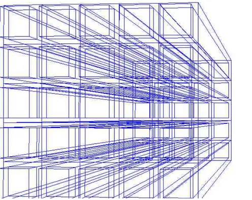
In order to investigate the possibility to improve the ToF PET using Cherenkov radiation, I wrote a ROOT program of the geometry of one PET detector, made by two opposite matrixes of lead glass coupled to SiPMs. The code is in Appendix A and Figure 2.3 shows the geometry of the system looking from behind one detector. This work could be further implemented in the future, where the physical process would be simulated with GEANT4 and the relative data collected.
Figure 2.3: image of a PET detector realized with a ROOT program, from the point of view of the back of one photodetector.
In the code each Cherenkov radiator designed is 3x3x30 mm3 in dimensions and for each block there is a 5x5 matrix of them. Between the radiators there is a 1 mm thickness of aluminum, which prevents internal reflections. As said in the previous paragraphs, internal reflections raise the photons detectability, so several studies (for example [12]) have been made wrapping the crystals with Teflon tape, which has a reflection coefficient of about 0.99 for incident rays of 400 nm wavelength [35]. However, as showed in previous studies
[34], in order to reach the best timing resolution, the internal reflections have to be limited as much as possible. Therefore there is the aluminum and due to the low efficiency and photons production of Cherenkov radiators, the detection will be based almost on single photons.
The best photodetectors identified are the SiPMs, mainly because of their high peak of photon detection efficiency. The SiPM chosen is the Hamamatsu S13360-3050PE 3x3 mm2 with 3600 pixels of 50 μm of size, according to the manufacture catalogue
[36]. Its dark count rate is 500 kcps, so it is very low, even compared to the Hamamatsu
SiPMs used in the 2015 study [34] and examined in the previous paragraph. In fact, the constant improvement of the SiPMs technology by the producers can bring soon very interesting results for ToF PET.
The site of annihilation is supposed to be at the center of the geometry, 40 cm away from each crystal in the final ToF PET system. In the simulations, in order to test the photodetectors, the point source could be located much closer to the detector, so that
the number of random coincidences is drastically reduced. In this case a 1.8MBq
22Na could be used as point source.
Figure 2.4: image of the ToF PET ring detector realized with a ROOT code
The Cherenkov radiators material is also fundamental in the system. The radiator needs a high refractive index and density, good transmission properties and a low cutoff wavelength. Lead glass is a good option, as it is cheap and many studies have already tested it as a Cherenkov radiator, obtaining decent timing responses. PWO could also be a candidate, mostly due to its higher relative efficiency.
In the designed system there is 1:1 coupling between the radiator and the SiPMs, which is absolutely needed in order to improve the gamma detection efficiency. This is explained well in [34], where a single sided efficiency of over 25% is claimed to be possible with this coupling.
With the experimental apparatus presented, the data could be acquired.
Once again, for different temperature conditions, the efficiency of the system would change. Therefore it would be suggested to vary the temperature from the room conditions down to about -25°C, with 1 or 2 °C intervals, and analyze the data at each step. The SiPM overvoltage as well can be changed. As it increase a better timing resolution is expected, but the dark counts are supposed to rise as well, so that the SNR slowly degrades.
In conclusion, a coincidence timing resolution at FWHM lower than 400 ps would be expected and the detection efficiency achieved should be pretty high as well. Only the data, however, will confirm or negate these hypotheses.
For further and more realistic simulations a ROOT code creating an entire ring of detector was also implemented and an image of the geometry can be seen in Figure 2.4. This would allow registering many more events, as it covers all the possible directions for the annihilation gammas, but the probability to detect random or scattered coincidences is also higher.
This whole work could be completed in a future study on Cherenkov ToF PET, as it might be my master thesis.
Conclusion
ToF PET detecting Cherenkov radiation is a very promising technique and important improvements of PET image quality may be obtained in the near future. Some interesting results have already been achieved. A timing resolution of 71 ps has been measured with a PbF2 as Cherenkov radiator coupled to a microchannel plate
photomultiplier (MCP PMT) [32]. This, however, was done under certain conditions and with very limited detection efficiency. Further studies have developed the idea that SiPMs could be a good choice for the photomultipliers, because of their higher peak of photon detection efficiency. A timing resolution of 422 ps was obtained in 2015 in what is claimed to be the first test of SiPMs for Cherenkov ToF PET [34]. Even if these were not the best SiPMs available on the market, a good single side detection efficiency was recorded. This leaves space to further studies on the topic and, if the dark count rate could be somehow considerably reduced, performances similar to common scintillator based systems could be soon achieved. The PET geometry proposed in Section 2.6 has a 1:1 coupling between the Cherenkov radiator and the SiPM. In addition to this, the last SiPM model manufactured by Hamamatsu is chosen. These two factors should improve the timing resolution of the system, but only simulations can tell by how much.
In conclusion, even if there are not many current studies on this topic, Cherenkov ToF PET is a very interesting technique. With improved photomultipliers
technologies, efficient radiators and optimized geometry conditions it could soon become competitive with the traditional scintillator based ToF PET systems and may exceed them.
![Figure 1.1: image of a typical PET facility [1].](https://thumb-eu.123doks.com/thumbv2/123dokorg/7447086.100749/8.892.222.691.607.953/figure-image-of-a-typical-pet-facility.webp)
![Figure 1.4: Above it is shown the QE for some photocathode materials and below the emission intensity (%) for some scintillators [12].](https://thumb-eu.123doks.com/thumbv2/123dokorg/7447086.100749/16.892.260.682.123.718/figure-above-photocathode-materials-below-emission-intensity-scintillators.webp)
![Figure 1.5: picture of a SiPM made of 24x24 small APDs. The side of the square measures 1 mm [15]](https://thumb-eu.123doks.com/thumbv2/123dokorg/7447086.100749/19.892.264.644.141.524/figure-picture-sipm-small-apds-square-measures-mm.webp)
![Figure 1.7: from left to right: true, random and scattered coincidence [5].](https://thumb-eu.123doks.com/thumbv2/123dokorg/7447086.100749/21.892.98.816.334.595/figure-from-left-right-true-random-scattered-coincidence.webp)
![Figure 1.9: on the left a representation of the reconstruction line backprojection process for the usual PET and on the right for ToF PET [20].](https://thumb-eu.123doks.com/thumbv2/123dokorg/7447086.100749/24.892.194.732.133.385/figure-representation-reconstruction-backprojection-process-usual-pet-right.webp)
![Figure 2.1: Regions of dominance for photons interactions with matter [26].](https://thumb-eu.123doks.com/thumbv2/123dokorg/7447086.100749/28.892.208.708.713.1078/figure-regions-dominance-for-photons-interactions-with-matter.webp)
![Figure 2.2: Geometry of the Compton scattering [27].](https://thumb-eu.123doks.com/thumbv2/123dokorg/7447086.100749/29.892.184.679.633.952/figure-geometry-of-the-compton-scattering.webp)