PhD Thesis
PhD course on Automatic, Robotics and Bioengineering XXIII (2008-2010)
SSD: ING-IND/34, ING-INF/06
Student: Whulanza Yudan Supervisor:
Prof. Arti Ahluwalia Ing. Giovanni Vozzi Dott. Claudio Domenici
University of Pisa
Interdepartmental Research Center ”E.Piaggio”
Pisa October 15, 2011i for application to locomotor tissue regeneration. Blend systems of synthetic materials with nanotubes or conducting polymer as fillers were characterised and used to realise 3D and tubular shaped scaffolds with bioactive properties. The term bioactive has been widening with the expansion of research in biomaterials, however it can be defined as a biocompatible material with the ability of inducing a required response from the host. Thus, the interaction between scaffold and organism is more profound than merely acting as a mechanical support. Conductive scaffolds have emerged as substrates that used electrical stimulation to enhance cell growth. There is much evidence and many experimental results which show that numerous tissues including bone, cartilage, skin, spinal nerves, and peripheral nerves respond favourably to electric fields. These outcomes motivate the development of conductive and bioactive biomaterials.
Different synthetic polymers, such as poly(-caprolactone), poly(lactic acid) and poly(lactic-co-glycolide) have been investigated as potential candidate for scaffold materials. Here, the use of carbon nanotubes as reinforcement fillers and electrical conductors in synthetic polymer was investigated due to the remarkable properties of carbon nanotubes such as high tensile strength, Young’s modulus, and electrical conductivity. Biodegradable polymers/carbon
ii have been characterised here and enabled us to identify the optimum concentration of CNT in the polymer composites. Additionally, analytical and numerical simulations were also proposed to model the mechanical and electrical characteristics.
A rapid prototyping method, PAM, was used to create a porous scaffold. This structure was aimed to provide appropriate diffusion of biochemical cues and elimination of cellular waste as well as to improve the mechanical properties. A simple 3D porous structure made of CNT/PLLA blend was realised and characterized. Additionally, tubular scaffolds were also fabricated and studied since there are still limited options available for scaffolds suitable for engineering tissues containing a luminal structure.
We also present a specific tailored material that can electroactively release and uptake a bioactive molecule for instance glutamate. Glutamate is an important neuromodulator and plays a major role in synaptic transmission. In this work we demonstrated that it was possible to use incorporate glutamate ions in to the conducting polymer through a simple adsorption. Our study has shown that these molecules can be effectively released upon electrical stimulation. Furthermore, we tried to explain the effect of various potentials on the release
iii Finally, an application of CNT/polymer composites for bone tissue scaffolds was performed. The tailored conducting property enables us to study the attachment of cells on the scaffolds via impedance monitoring. Furthermore, these composites were shown to be highly biocompatible for human osteoblasts and hepatocytes.
1
General Introduction
1. Tissue Engineering and Scaffolds Design
Basic concept and traditional approach of tissue engineering includes a scaffold that provides architecture for cell seeding which can organize and develop into the desired tissues and organs in vitro before implantation. The biomaterial scaffolds can provide the initial biomechanical profile for the seeded cells until they fabricate their own natural extracellular matrix. During the formation, deposition and organization of the newly generated tissue matrix, the original scaffold is either degraded or metabolised; finally leaving a vital organ or tissue that restores, maintains, or improves tissue function [Stock et al 2001].
Hence, the scaffold has a critical requirement to provide a suitable environment for cell growth and development. As far as engineering design is concerned, the scaffold should meet three basic requirements: biocompatibility, mechanical strength, and stability. These three properties mainly depend on the selection of material and the architectural creation of the matrix.
The materials of the scaffolds can be either natural polymers or synthetic polymers. Natural polymers have many advantages, including natural biocompatibility and enzymatic biodegradability. The common natural
hundred times their dry weight. Owing to their water-retention and optically transparent properties, these hydrogels have been used in cell encapsulation and to induce differentiation and growth. They have also been observed to be suitable for nerve and cartilage regeneration (Agrawal and Ray 2001, Karageorgiou and Kaplan 2005). Collagens are the most abundant proteins in the body and are the major components in bone, cartilage, skin, ligament, and tendon. There are at least twenty types of collagen. Among them, collagen type I has unique mechanical and physiological properties that are suitable for repairing skin, cartilage, nerve, and tendon tissues. The main drawback of natural polymers is their natural variability as well as the lack of an effective sterilising method for them. In addition, only a few natural polymers have good mechanical strength, which is essential for hard tissue such as bone or dental tissue (Papenburg et al. 2007).
On the other hand, synthetic polymers scaffolds can be easily sterilised. Synthetic polymers have several advantages: they are cost-effective and also have controllable physical properties. Their physical properties like molecular weight, melting point, solubility, and mechanical strength can
3 be modified by changing reaction conditions. Most synthetic polymers can be processed by melting or with solvents, which is very important for large-scale production. Since the molecular weight of synthetic polymers can be controlled by synthetic or purification procedures, their physical properties can be well-defined (Gunatillake and Adhikari 2003). FDA approved polymers, such as polyl-L-lactide acid, poly(lactic-co-glycolic acid) or poly -caprolactone, are the primary synthetic materials for matrices in various tissue engineering applications, but they lack the necessary mechanical strength to mimic the target tissue that is being generated (Engelberg and Kohn 1991, Gupta and Kumar 2007, Anathasiou et al. 1996, Karp et al. 203). Table 1.1 shows the compressive modulus of hard and soft tissues and most relevant synthetic polymers.
Apart from the basic properties of material, scaffold design must also address the issue of topological side such as creation of porous constructs. These porous constructs provide appropriate diffusion of biochemical cues and cellular waste [Hollister et al. 2002, Hutmacher et al. 2000, Li et al. 2001]. Thus, an extra effort needs to be made to combine the critical properties of permeability and strength. Additionally, it also should be easily produced into complex 3D anatomical-like constructs. Various scaffold fabrication techniques over the past decade have resulted in significant progress in creating
polymers . Material Tm (oC) Tg (oC) Compressive test Modulus (GPa) Degradation time (Month) Hard tissue -- -- 3-30 - Soft tissue -- -- 0.05-0.5 - Poly-glycolide 225-230 35-40 7 6-12 Poly-L-lactide 173-178 60-65 2.7 >24 Poly-DL-lactide Amorphous 55-60 1.9 12-16 Poly(DL-lactide-co-glycolide) Amorphous 45-55 2 1-6 Poly(-caprolactone) 58-63 -65 4 >24
Ultimately, interactions between cells and extracellular matrix are key factors to study cell migration, proliferation, differentiation, and apoptosis, which all are critical functions for a tissue-engineered construct. Unfortunately, these requirements are not fully understood by researchers and the study of the complete set of biological requirements that must be satisfied before being able to function as a true biomimetic substitute is currently the topic of intense research [Moit et al 2005]. Additionally, another limitation in current tissue
5 engineering method for the locomotor system is the inability to develop multiple tissue types (i.e. bone, cartilage, muscles, nerves) within a single scaffold structure in a defined manner.
2. Thesis background
This thesis focuses on designing active biomimetic scaffolds that are tailored specifically for optimising the interaction between cells and their host. In the context of the present study, the application of tissue engineering of locomotor tissue is the main interest.
The locomotor apparatus is a multi tissue that gives humans the ability to move using muscles skeletal tissue. The musculoskeletal system provides form, support, stability, and movement to the body. It is made up of bones, muscles, cartilage, tendons, ligaments, joints and other connective tissue that supports and binds tissues and organs together. The musculoskeletal system's primary functions include supporting the body, allowing motion, and protecting vital organs. Figure 1 shows a block diagram representation of the locomotor system and its division in three subsystems.
(CNS), comprises the brain and the spinal cord, and the Peripheral Nervous System (PNS), the nerves connecting the CNS to the rest of the body. This block receives information from the sensory system regarding the position of the body and the external environment, and controls the muscular subsystem.
7 Muscular Subsystem: This subsystem includes the muscles and the tendons of the body. Information is sent from the CNS, via the PNS, to the muscles. This block keeps track of the physical state of the muscles and tendons (length, contractile velocity etc) and describes how force is produced in the muscles and tendons.
Skeletal Subsystem: This subsystem includes the bones, ligaments and cartilage of the body. The geometry and position of the relevant parts of the subsystem are known. The muscular subsystem controls this block, through muscle contraction.
3. Clinical problems and tissue engineering approach for the locomotor system
Because of close relation between above three sub-systems, disorders of one of these subsystems may also affect the whole system and complicate the diagnosis of the disorder's origin. Diseases of the locomotor system mostly encompass functional disorders or motion discrepancies; the level of impairment depends specifically on the problem and its severity. Figure 2 pictures the WHO report on diseases related to musculoskeletal problems.
The World Health Organization and the United Nations are calling the years 2000–2010 the Bone and Joint Decade, as rheumatic diseases cause more pain and disability than any other disease group. It can be seen that the musculoskeletal-related diseases are experienced by averagely 650 per 100,000 inhabitants. They have identified osteoarthritis, rheumatoid arthritis, osteoporosis, and low back pain as the four major musculoskeletal conditions causing the largest burden. Injuries to the musculoskeletal system also fall within this category, particularly sports injuries. The burden of these diseases is measured by the pain and disability caused.
Musculoskeletal disorders are the most frequent cause of physical disability for people in developed countries. The prevalence of
9 musculoskeletal disorders increases with age. Internationally, musculoskeletal conditions are the most common causes of chronic disability and have increased by 25 per cent in the last 10 years.
A more detail on the common problems and tissue engineering approach are as followed:
3.1 Nervous system
In the peripheral nervous system, axons have the ability to regenerate over small defects when appropriate surgical repair techniques and guiding strategies are used. The age of the individual is the most important predictor of outcome following nerve injury and repair. Children often regain normal function after injury, but adults and elderly individuals experience slow or absent functional recovery. More than half of individuals over the age of 50 do not achieve any functional recovery after nerve repair [Verdu et al 2000]. Besides clinical factors such as age and health of the patient, the outcome of the injury is dependent on the site of the lesion, the degree of disruption of the surrounding tissue, the integrity of the vascular network and the degree of cellular damage [Hall 2005].
the diameter of the nerve being repaired are used. This strategy involves securing the proximal and distal ends of the nerve to the two open ends of the NGC. These tubes physically guide developing axonal processes towards their distal targets. In addition to restricting migrating cells and sprouting processes within the confines of the tube, such systems create a space for increasing the local growth factor concentrations and act as a barrier to minimise the infiltration of fibroblasts and other inhibitory or scar forming entities that would otherwise inhibit the normal regenerative process [Tresco 2000].
11 Among the artificial materials, synthetic tubular NGCs have shown the most promising results so far. The use of NGC reduces tension at the suture line, protects the regenerating axons from the infiltrating scar tissue, and directs the sprouting axons toward their distal targets. The hollow space of NGCs can be filled with growth promoting matrix, growth factors and/or appropriate cells [Dahlin and Lundbort 2001]. The NGCs can be used as an excellent experimental tool, to control the distance between the nerve stumps, test the fluid and tissue entering the channel, and vary the properties of the channel [Valentini and Aebischer 1997].
3.1.2 Challenges for the design of guidance channels
In designing a polymer nerve guidance channel, its characteristics, such as, porosity, roughness, and electrical activity, can be modified to enhance its properties. An ideal guidance channel should be biodegradable, should not elicit immune response, have electrical activity and be porous. It should also be able to incorporate support cells, neurotrophic factors, and internal oriented matrices. Also, it should be flexible, readily available and easy to fabricate [Hudson and Evans 2000].
repairing nerve injuries. Even in cases where significant regeneration has been observed, it has been over short nerve gaps, about 10 mm. However, in clinical applications for humans, there is a need to bridge nerve gaps greater than 10 mm. Even in the best case of autografts, complete functional recovery is usually not achieved, due to misdirection of growing fibers, neuronal cell death, or atrophy/death of the denervated target organ [Meyer et al 1997, Zhao et al 1992]. Therefore, it is still a challenge to develop alternative approaches for enhancing peripheral nerve regeneration to the level comparable to autografts, and further to exceed the results obtained from autografts.
3.2 Muscle
The damage of skeletal muscle that occurs in a variety of muscular diseases or injuries can disrupt the sarcomeric organization, membrane integrity, excitation‐contraction coupling and calcium homeostasis, cause the weakening and loss of muscle fibres and hence significantly impair muscle function. Myopathies result in severe muscle loss and dysfunction. Duchenne muscular dystrophy (DMD) is a lethal inherited
13 muscular disorder caused by the defected dystrophin gene on the X‐chromosome. Spinal muscular atrophy (SMA) is caused by the degeneration of motor neurons in the spinal cord [Nowak and Davies 2004].
In addition, severe ischemic injuries to skeletal muscle can induce extensive muscle cell death and lead to loss of muscle mass and function [Lunn and Wang 2008, Midrio 2006]. Significant muscle loss can also result from traumatic injuries, tumor ablation and congenital defects. Moreover, the loss of muscle mass and strength can occur during biological aging, in a process known as age‐related sarcopenia *Petrasek et al 1994].
3.2.1 Tissue engineering approach
Despite the existence of satellite cells that are capable of regeneration, their incidence in skeletal muscle is low (1‐ 5%) and dependent on age and muscle fiber composition. Hence the endogenous population of satellite cells is often insufficient to replace the large number of necrotic muscle fibers and restore the function of the failing muscle due to severe muscular diseases or injuries [Allen et al 1997]. Currently, autologous
promote cell survival upon the implantation of a large number of cells and localised cell distribution at the engraftment site [Langer and Vacanti 1993]. In addition, in vitro engineering of functional mature skeletal muscle tissues could bring several unique advantages that would lead to future effective treatment of specific muscular disorders or injuries, such as traumatic injury. These advantages are: 1) the ability to design custom tissue architecture for precise structural repair at the site of injury and 2) the ability to precondition scaffolds for specific mechanically or metabolically demanding host environment.
3.2.2 Ideal properties of engineered skeletal muscle tissues
The engineered skeletal muscle tissue is expected to have several ideal structural and functional properties in order to effectively restore lost muscle function. Structurally, from a biomimetic perspective, the engineered skeletal muscle tissue should: 1) be adequately large and thick, 2) consist of densely packed and highly differentiated muscle fibres, and 3) mimic the aligned architecture of native muscle. These structural characteristics would ideally provide sufficient and
15 appropriately distributed active forces to directly augment the contractile function of the host muscle [Bian and Bursac 2008].
3.3 Bone
The two types of bone cells participating in the remodelling of bone, osteoclasts and osteoblasts, have diametrically opposed actions which are influenced by numerous factors [Buckwalter 1995]. Osteoclasts, bone resorbing cells, rest directly on the surface subjected to resorption during activity. Osteoclasts are derived from the hematopoetic monocytic cell lineage [Buckwalter 1995]. Active osteoblasts secrete collagen fibrils and other extracellular matrix components together forming an unmineralised matrix (osteoid). Osteoblasts become completely embedded in the bone they produce and are then called osteocytes, which are no longer able to actively form bone.
Cortical and trabecular bone is created and re-created by the remodelling action of osteoblasts and osteoclasts which allows repair of damaged tissue and allows the adaptation of bone structure to altered loading condition. Remodelling begins with resorption by osteoclasts which secure themselves to bone surfaces and tunnel into the bone. The next step is bone formation; osteoblasts are attracted to the cavities
Figure 4: Schematic illustrating cellular activity during the bone remodelling process; (1, 2) osteoclasts resorb damaged tissue and (3,4) osteoblasts refill the cavity with newly formed osteoid, which is subsequently mineralised.
The ability of bone to regenerate rather than form scar tissue is a well-known characteristic of bone, which produces a structure physiologically and biomechanically indistinguishable from the original. The dynamic interactions among cells and cell-derived molecules at a fracture site
17 ensure complete regeneration of bone. The bone repair process begins with an inflammatory response (with neutrophils and macrophages) present that causes granulation tissue to proliferate into the wound site. It is through the granulation tissue that capillaries, fibroblasts and osteoprogenitor cells are brought into the wound site. Over time the newly formed woven bone is remodelled and replaced by lamellar bone.
3.3.1 Tissue engineering approach
The strategy exploits the capacity for progenitor or stem cells to grow in the laboratory (in vitro) under conditions that imitate the in vivo biochemical and physical environment. By seeding these cells onto porous biocompatible scaffolds it is possible to produce functional replacement tissue for clinical use in other tissue types.
3.3.2 Challenges for the design of bone models
Much study has been dedicated to understanding the desired properties and structure of biocompatible scaffold materials to encourage bone cell attachment and matrix formation [Williams et al. 2005, Mathieu et al. 2006, Marra et al. 1999, Yang et al. 2004; MacArthur and Oreffo 2005]. However, to date these approaches have failed to produce bone tissue strong enough to bear load or be used clinically. For this reason, a
4. Thesis objective
In order to design and microfabricate active biomimetic scaffolds for the locomotor system, three specific aims for this research project were as follows:
Aim 1: Active biomimetic scaffold for bone.
Bone tissue is rigid; it has a highly porous architecture and is also sensitive to electrical stimulation as the tissue has piezoelectric properties.
The aim was that a layer by layer microfabrication of material composed of synthetic polymer reinforced with carbon nanotubes would enable realisation of a porous architecture with appropriate porosity and stiffness.
Aim 2: active biomimetic scaffold for nerve
My aim was to create scaffolds with properties tailored towards electrically controlled release and uptake of incorporated neuro modulators useful for nerve stimulation using conducting polymers.
19 In addition tubular scaffolds consisting of a blend of polymer and conducting polymer were investigated as nerve guidance channels in peripheral nerve regeneration capable of release of growth factor or bioactive molecules.
Aim 3: the third aim was to develop softer scaffolds use the same microfabrication technique for tendons, ligaments and the passive components of muscle tissue.
Tendons and ligaments are in in fact the ‘interface’ tissues and are critical in biomechanically linking the locomotor system. Various microfabrication techniques, materials and architectures were investigated from mechanical, topological and electrical point of view.
5. Significance of the Thesis
It is predicted that the development of bioengineering scaffolds will be similar to the evolution of medical devices for implants. The state-of-the-art of engineering design helps to define the frontiers of research. This can be illustrated by graphing developments in bioengineering complexity through the time.
Early bioengineered scaffolds were 2D films placed in bioreactors for giving external guidance for cell growth. Later, scaffolds with a more profound interaction with the cells were designed with the application of
Figure 5: The evolution of implant devices from bio passive (inside the body), bio-active, bio-reactive, and bio-proactive. Each transition requires new technologies to cross the research frontiers are indicated by arrows (adapted from Simms 2008)
Bio-passive technologies were enhanced with the application of bio-active materials, such as coated with materials to exhibit cell proliferation at the surface. These may be categorized as bio-active
21 devices. In fact the definition of biocompatibility was broadened around this time: previously the word biocompatibility had been almost synonymous with inert whereas now biocompatibility means that the material evokes the required response from the host rather than just being inert.
Bio-reactive devices emerged next. Scaffolds with growth factor, drugs, bioactivity integrated into them became a reality. Also at this time scaffold systems which take a signal from the local environment using a biosensor (either passive or active) came on the scene. This signal causes the device to react as part of a feedback control process, e.g. neuroprosthetics and active drug-delivery devices are in this category.
Scaffolds that are responsive to the genetic profile of the individual may be envisioned (the last category on figure 5). Clearly this is very much in the future commercially. They do not just respond to diseases as they become noticeable in the patient’s physiology, but rather examine for genetic tendency when implanted and accessing databases to analyse them.
The long term goal of this project is to generate bioactive to bioreactive scaffolds particularly for bone and nerve tissue regeneration. Utilization of conducting scaffolds enables us to do online system monitoring of
channels with active electrical properties aim to electrically control the immobilised bioactive molecules such as neuromodulators or nerve growth factor for instance. Hence, they promote the cell growth during the nerve grafting.
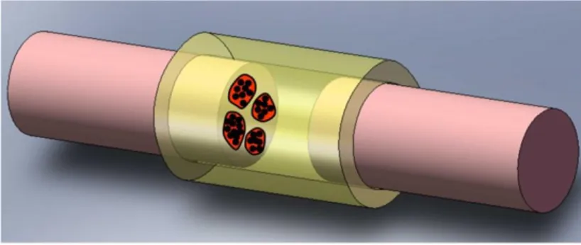
Figure 6. An example of an assembled complex structure
Ultimately, using a bottom-up approach, different materials with different microstructures might be embedded and assembled into the scaffold as it is being built up as single structure. For example, an
23 assembly to more complex structures such as complete bone, tendon, muscle constructs depicted in figure 6.
6. Thesis Outline
This thesis is outlines as follows:
Chapter 1 presents an overall approach to the material design of scaffolds. The mechanical and electrical characterisation of a polymer filled with nantobubes will be presented here. Mechanical model for composites are highlighted as well as the classic percolation theory for conduction.
Chapter 2 presents fabrication methods for 3D conductive scaffolds using rapid prototyping method. It elucidates the characterisation of realised scaffolds mechanically and electrically.
Chapter 3 specifically presents the realisation and characterisation of conductive tubular scaffolds for application as connective tissue in bone or muscle tissue.
Chapter 4 presents the characterisation of bioactive i.e. glutamic ion in release and uptake studies on conducting polymer for neural application.
polymer so that it is usable in supporting structure as scaffolds.
Chapter 6 elaborates the characterisation of tubular shapes made from poly(-caprolactone) and polythiophene blend. This pioneering study was aimed at applying the tubular polymer blend as a peripheral guidance channel tailored with conductive properties.
Chapter 7 explicates the application of conductive 2D scaffolds in cell sensing during in vitro cell seeding. Impedance characterisation and model are presented here.
After a summary of the results, conclusions and recommendations for the future work of this research are presented in the final part.
25
1. Material Selection, Design and Characterisation
Abstract
Composites comprising CNTs and the biocompatible polymers are of special interest due to their potential for specific biomedical applications. We report the preparation of the SWNT in synthetic biodegradable polymer PLLA, PCL and PLGA composite in bone scaffolds application. Here, ultrasonic energy was used to uniformly disperse SWNT in solutions and to incorporate them into composites without chemical pre-treatment. The mechanical properties of these composites have also been investigated. Addition of around 1% SWNT found to increase the elastic modulus in factor of 3. The elastic modulus of samples compared well to classical micromechanical models. Additionally, specific composition where the composites tend to brittle also reported.
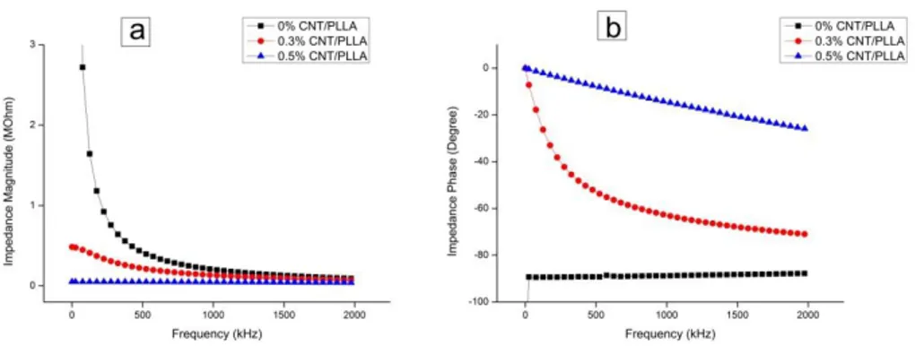
The AC conductivity of the composite also increases as the SWNT loading is increased. Such behaviour can be described by a percolation mechanism in which a percolation threshold at about 0.3 wt % SWNT loading. The presence of SWNTs at 0.5 wt. % fraction transforms the film from insulating to conductive with the maximum end conductivity of around 0.05 -1.5 S/m. This chapter also elucidates the basic relationships between mechanical, electrical property and degree of dispersion of single walled carbon nanotube reinforced polymer composites.
26 1.1 Introduction
Due to the variation in mechanical properties required in ‘soft’ versus ‘hard’ Tissue Engineering applications, the fabrication of these two scaffolds generally use different classes of biomaterials. For soft TE applications, e.g. skeletal muscle or cardiovascular substitutes, generally a wide variety of polymers are applied. On the other hand, hard tissue replacements, e.g. bone substitutes, are generally based on more rigid polymers, ceramics and metals.
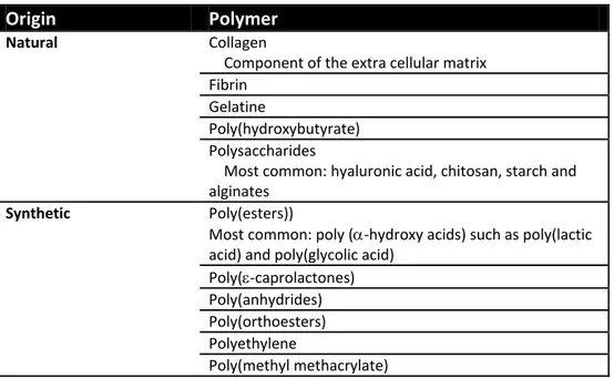
Table 1.1: Soft tissue TE material
Origin Polymer
Natural Collagen
Component of the extra cellular matrix Fibrin
Gelatine
Poly(hydroxybutyrate) Polysaccharides
Most common: hyaluronic acid, chitosan, starch and alginates
Synthetic Poly(esters))
Most common: poly (-hydroxy acids) such as poly(lactic acid) and poly(glycolic acid)
Poly(-caprolactones) Poly(anhydrides) Poly(orthoesters) Polyethylene
Poly(methyl methacrylate)
Table 1.1 lists polymers extensively applied in scaffold fabrication for ‘soft’ TE applications. Apart from single polymers, scaffolds are also commonly fabricated from co-polymers of two or more polymers (not
27 listed) to improve the overall characteristics; co-polymers generally have an average of the mechanical properties of the incorporated single polymers.
Scaffold fabrication for hard TE applications employs a wider variety of materials; including polymers, ceramics, composites and metals. Table 1.2 presents materials extensively used in hard TE, besides the polymers already listed in Table 1.1. Often, polymers alone might not have sufficient mechanical strength, which can be improved by adding reinforcements resulting in composites. Herewith, combining two or more classes of materials improves the mechanical properties, similar to the principle behind co-polymer.
Table 1.2: Hard tissue TE material
Class of material type
Crystalline ceramics Hydroxyapatite Tricalcium phosphate Calcium metaphospate
Amorphous glasses Silica Bio-glass
Composites Hydroxyapatite/ Poly(-caprolactones) Chitosan or collagen /polyvinyl alcohol Tricalcium phosphate/ poly(lactic acid) Etc
Metals Stainless steel Titanium Alumina
Polymers and polymer-ceramic composites are more and more frequently utilized to overcome the drawbacks associated with metals and ceramics in many orthopedic applications. Different types of
28 biocompatible polymers are known. Beside natural polymers, such as polysaccharides, gelatine and protein-based polymers, synthetic biocompatible polymers are also used. They can be subdivided into biodegradable polymers, like poly(L-lactide) and poly(ortho-esters), and non-biodegradable ones, for example poly(hydroxyl methacrylate), poly(methyl methacrylate) (PMMA) and poly(ethylene glycol).
Biodegradable polymers have been widely investigated, and in the last decade they have been thought suitable for tissue engineering. Terms such as absorbable, resorbable, and degradable, with or without the prefix ‘bio’, are inconsistently used in the literature, and lately, distinguishing between them is quite difficult. The most often used expression is ‘biodegradability’, which can be defined many ways; e.g. the capability of being decomposed (broken down) by natural biological processes.
Due to the interaction with tissues and organs, biocompatibility is the prime concern over all the material branches. The properties of polymeric biomaterials are similar to other biomaterials, i.e. sterilisability, adequate mechanical and physical properties, and manufacturability. It is noteworthy that body fluids might solve the entrapped impurities in a polymer matrix. Furthermore residual compounds (e.g. monomers, initiators) resulting from polymerization or processing could modify some characteristics, such as crystallinity, porosity, toxicity etc. [Hutmacher 2000, Griffith 2000].
Although thousands of such polymers exist, only a few of them have had success in medical applications. Among the synthetic, biodegradable polymers, the family of aliphatic polyesters dominates due to their
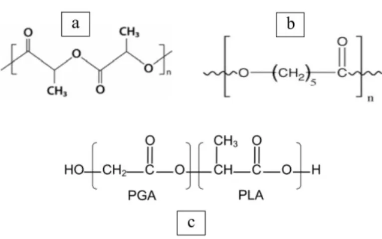
29 beneficial mechanical, degradative and biocompatibility characteristics. In this group one of the favourites is poly(L-lactic acid) (PLLA), but also the poly(glycolic acid) (PGA) has relevance in medical uses. Moreover, their copolymers are widely used, due to the fact that the degradation time can be set by the changing the proportion of the polymers [Park 1995, Anderson and Shive 1997].
Pure PLLA does not have adequate mechanical properties for certain medical applications such as bone scaffolds or bone fixture; therefore new studies have been conducted. In late nineties Weiler and Gogolewski reported on solid state extrusion of pure PLLA which is able to achieve almost 200% tensile strength improvement. On the other hand, Törmälä et aldeveloped a technique for self-reinforcing (SR) of PLLA which improved the material strength until more than 300 [Törmälä et al 1990, Rokkanen et al 2000].
In this chapter, we discussed on reinforcing the synthetic biodegradable polymers with carbon nanotubes as filler. The unique properties of CNTs such as extremely high strength, low density and high electric conductivity offer advantages over other nano-fillers [An et al., 2004; Meyyappan, 2005]. Moreover CNTs have dimensions which are comparable to ECM molecules such as collagen and laminin, and are reported to sup- port cell adhesion [Freire et al., 2002; Kleinman et al., 1985; Luckenbill-Edds, 1997; He and Bellamkonda, 2005]. Carbon nanotubes are in fact extensively explored for biomedical applications [Balasubramanian and Burghard, 2006; Harrison and Atala, 2007; Zhang et al., 2005], particularly those involving scaffolds for neural and bone tissue. For example neurons grown on a CNT network are reported to exhibit better signal transmission [Lovat et al., 2005], possibly due to the
30 fact that CNTs form tight contacts with neuron membranes leading to electrical shortcuts [Cilia et al., 2008]. Moreover, as CNTs behave like an inert matrix, combined with other natural or synthetic materials in biocomposites, they can be effective in bone tissue engineering applications. Carbon nanotube based substrates have been shown to support the growth of osteoblastic cells which can be expected to become functional bone [Li et al., 2005; Zhang et al., 2005; Pankratz et al., 2009].
However, the effective utilization of the excellent properties of nanotubes in composite applications strongly depends on the ability to disperse CNTs homogeneously throughout the matrix, as well as on the interfacial bonding and the content of nanotubes in the matrix. Producing well-dispersed carbon nanotubes in a composite is difficult because the addition of solid ‘powder’ (carbon) in a liquid polymer in the early mixing stages often leads to phase separation between the carbon and the polymer matrix due to low interfacial bonding between the two. Several methods for enhancing interfacial adhesion between CNT and the polymer matrix are described [Coleman et al. 2006]. Following a simple two-solvent mixing method, a tolerable dispersion with low content of CNT in a polymer matrix has been reported by the authors [Pioggia et al. 2007].
Here, we investigate three synthetic biodegradable that FDA approved which are poly(lactic acid), poly- caprolactone and poly(lactic-co-glycolic acid) to be used as candidate material for scaffolds. We were mostly interested in the shifting of mechanical strength and electric conductivity properties. Ultimately, the viability of cells on our polymeric material also was described.
31 1.1.1 Polymer matrix enhancement
The artificial matrix plays a very important role in tissue engineering. It is responsible for defining the space the engineered tissue occupies and for aiding the process of tissue development [Harrison and Atala 2007]. One of the few requirements that the matrix has to fulfil is mechanical stability, which is crucial for maintaining the predesigned tissue structure. Mechanical stability mainly depends on the selection of the biomaterial and the architectural design of the matrix. Although polymers, such as PLLA (polyl-L-lactic acid) or PLGA (poly(lactic-co-glycolic acid)), are the primary materials for matrices in various tissue engineering applications, they lack the necessary mechanical strength (see figure 1.1).
Figure 1.1: Comparative mechanical property of bone and several materials in TE applications [Yuehuei 2000]
The extraordinary mechanical properties of carbon nanotubes make them very attractive and promising as reinforcing fillers for the
32 production of a new generation of tissue matrices. Data reveal that carbon nanotubes dispersed in a polymer significantly improve the mechanical properties of the composite [Coleman etal 2004, Liu etal 2004, Coleman 2006]. Up to now, carbon nanotubes have been put into a host of different synthetic polymers as well as into biopolymers. Carbon nanotubes merged with chitosan, for example, showed a significant enhancement in the mechanical strength of the composite [Wang etal 2005]. By incorporation of only 0.8 wt% of CNTs into the chitosan matrix, the mechanical properties of the nanocomposite, including Young’s modulus and tensile strength, were improved by about 93 % and 99 %, respectively.
Apart from polymer enhancement, carbon nanotubes have also been used to reinforce ceramic matrices. Gao et al. [Gao etal 2006] successfully fabricated CNTs/BaTiO3 composites, where the addition of 1 wt% of CNTs increased the fracture toughness by about 240 %. Using plasma-sprayed techniques, CNTs have been uniformly distributed in a brittle hydroxyapatie (HA) bioceramic coating, improving the fracture toughness of the nanocomposite by 56 % [Balani etal 2007].
The above-mentioned studies demonstrate that the mechanical properties of matrices can be significantly improved with CNTs. Moreover, the fact that the addition of very small amounts of CNTs is sufficient for matrix enhancement may counterbalance their non-degradable nature.
Whereas mechanical reinforcement was the initial motivation of using carbon nanotubes, there is evidence that CNTs can accelerate and direct cell growth. Several in vitro studies have been conducted investigating
33 the interaction between CNTs or nanocomposites and mammalian cells. It was shown that a collagen matrix with embedded SWNTs sustained a high cell viability of smooth muscle cells [MacDonald etal 2005]. The work by Zanello et al. [Zanello etal 2006] examined the proliferation and function of osteoblast cells seeded onto five differently functionalized carbon nanotubes. This study showed that bone cells prefer electrically neutral CNTs, which sustained osteoblast growth and bone-forming functions. The follow-up study investigated the adhesion properties of osteoblast, fibroblast, neuron, and astrocyte cell on polycarbonate urethane/carbon nanotube (PU/CNT) nanocomposites [Webster etal 2004].
The possibility of using nanotubes as substrates for nerve cell growth and as probes of neural functions at the nanometer scale has been reported by Mattson [Mattson et al 2000]. They showed that neurons, which were grown on CNTs functionalized with a bioactive molecule, 4-hydroxynonenal, developed multiple neurites and extensive branching. The ability to control the characteristics of neurite outgrowth also became possible by manipulating the charge carried by the functionalized carbon nanotubes. As shown by Hu [Hu et al 2004], neurons plated on positively- charged CNTs exhibited more numerous growth cones, longer neurite outgrowth, and more neurite branching in comparison with the neurons grown on negatively-charged nanotubes.
Carbon nanotubes have also been used to create electrically-conductive polymers and tissue matrices with the capacity to provide controlled electrical stimulation. It has been reported that current-conducting CNT/polymer composites promote various osteoblast cell functions. By applying alternating current to these nanocomposites, an increase in
34 osteoblast proliferation by 46 %, and calcium deposition by 307 % has been observed [Supronowicz et al 2002]. This result suggests that CNT- based composites may be used to stimulate bone formation. Other studies have been directed toward exploiting the electrical properties of CNTs for the purpose of healing neurological and brain-related injuries.
1.1.2 Percolation theory
The percolation theory may be used to describe the structure and property transitions in filled polymers. The structure and properties changes of such composites can usually be referred to the concentration of the filler at which the interconnected clusters of the filling material reach a well defined threshold. For concentrations above this threshold it can be seen to be an infinite cluster (formed by filler) that connects two sides of an arbitrarily large sample. This work is focused on the percolation theory in terms of transition of the rheological and electrical properties of the CNT/polymer composites.
Systems composed of an insulating material and a conductive filler experience an insulator-conductor transition at the electrical percolation threshold. The electrical percolation threshold is the minimal volume fraction of fillers so that a continuing conductive network exists in the composite. Above this volume fraction, the electrical resistivity of the composite is relatively low. Below the electrical percolation threshold, the compound essentially behaves as an insulator. There are different models and theories that define an insulator-conductor transition and a corresponding percolation threshold of the conductive filler
35 concentration with regard to the DC and AC conductivity [Potschke et al 2003, Kilbride et al 2002, Potschke et al 2002].
The compositions of different materials have, in the past, been of great significance and attract a great deal of interest in the physics. Various properties can be attained by the formation of hybrid systems. The presence of conductive fillers like CNTs within an insulating matrix material alters the electric properties of the composite [Kim et al 2005, Barrau et al 2003]. The composite becomes conductive above a critical value – percolation threshold that defines the insulator-conductor transition. The electrical percolation threshold depends on many factors including the size and shape of the filler, matrix properties, preparation method, filler properties, dispersion of the filler within matrix, interaction between compounds etc. A high aspect ratio and a good dispersion of CNTs in a matrix enable percolation at a very low weight fraction of nanotubes.
While the effective medium theory refers to the composites’ dielectric properties below or in the vicinity of the electrical percolation threshold, where the system remains insulating; the electrical percolation theories concern systems with filler concentrations above the electrical percolation threshold. In the classical electrical percolation theory, the relationship between the composite conductivity and the concentration (p) above the percolation threshold (pc) can be described by a scaling law [Barrau et al 2003, Kilbride et al 2002, Potschke et al 2003]:
36 where p0 is a constant parameter and t the critical exponent that is
dependent on the dimension of the lattice. According to the percolation theory, a theoretical value of t 2 for a percolation network in three dimensions was estimated. Value of the critical exponent t obtained by fitting a power law relation to the experimental data was shown to lay in the range of 1.1 - 3.1 [Barrau et al 2003, Kim et al 2005, Kilbride e tal 2002, Potschke et al 2003].
Figure 1.2: Schematic of CNTs/polymer nanocomposite with isotropic orientation of nanotubes [adapted from Du et al 2004]
At low concentration of CNTs (left), the rheological and electrical properties of the composite are comparable to those of the host matrix. Rheological percolation threshold takes place when the distance between nanotubes is comparable to the average radius of gyration of the polymer (center). Electrical percolation threshold (right) is observed
37 when nanotubes are sufficiently close to each other to form a percolating conductive path [Du et al 2004].
1.1.3 Material Description
This section only describes a selection of widely used materials and focuses more on the materials used in this thesis. For in-depth information on other frequently used materials for scaffold fabrication, excellent reviews are available [Agrawal and Ray 2001, Karageorgiou and Kaplan 2005, Gunatillake and Adhikari 2003, Ramakhrishna et al 2001, Rezwan et al 2006].
38 1.1.3.1 Poly(lactic acid)
In this thesis, we primarily use one of the most common and well known biomaterials: poly(lactic acid) (PLA). PLA belongs to the polyester family, as is the case for the vast majority of biodegradable polymers. PLA exists in different isomeric forms, namely semi crystalline D- (PDLA), semi crystalline L(+) (PLLA) and amorphous racemic D,L (PDLLA).
PLA degrades by bulk hydrolysis and leads to the production of lactic acid. In case of PLLA, degradation results in L(+) lactic acid, a substance that exists in the human body under natural circumstances as well, therefore PLLA is generally preferred over PDLA [Engelberg and Kohn 1991].
The degradation of PLLA in vitro occurs in the order of years, whereas in vivo degradation takes approximately 8-10 months; degradation of PDLLA is in the order of months [Hutmacher 2000, Laaksovirta 2003]. The degradation rate of PLA scaffolds highly depends on amongst others molecular weight and polydispersity of the polymer, process parameters and scaffold design [Hutmacher 2000].
PLLA exhibit superior mechanical strength compared to PDLLA due to its semi-crystalline nature (10-40 % crystallinity) and higher Tg of around 65 °C versus around 54 °C for PDLLA [Joziasse etal 1996]. Therefore, mostly PLLA is selected over PDLLA as scaffold material, as is also the case for the vast majority of the work presented in this thesis.
39 Another polymer selected of the polyester family is poly(ε-caprolactone (PCL), a semicrystalline rubbery polymer with a very low Tg of around -60 °C [Engelberg and Kohn 1991]. Generally PCL degrades by bulk hydrolysis like PLA, although also enzymatic degradation can occur under certain conditions. Degradation is significantly slower compared to PLA due to limited fluid inflow as result of the close packed macromolecules; in vivo degradation time extents to over 2 years [Hutmacher 2000, Coombes 2004]. Therefore, PCL is mainly suitable for long term implants.
PLGA was chosen for this research as it is a biodegradable polymer that can be electrospun, and previous groups have shows cell attachment upon this polymer (Aviss et al., 2010; Kumbar et al., 2008; Pan et al., 2008; Xin et al., 2006). This polymer is biodegradable and has been shown to generate nanofibres when electrospun and is an elastomer. PLGA is a random co-polymer of lactide and glycolide, and has already been used for various medical procedures e.g. sutures and drug delivery systems (Gilding and Reed, 1979; Lee et al., 2007).
A co-polymer of lactide and glycolide provides a useful method to combine the different properties of the two components. Because poly-lactide (PLA) has a hydrophobic methyl group its degradation rate is much slower than that of poly-glycolide (PGA). PGA has a 46-53% crystallinity (Gilding and Reed, 1979) thus processing this polymer alone using systems that require dissolving the polymer in solvents can be difficult; in contrast PDLLA is amorphous so dissolving in solvents is not a problem. By combining the two polymers to form a co-polymer it is possible to tailor the end product by controlling the ratio of the polymers.
40 1.1.3.4 Carbon nanotubes
The first carbon fibres of nanometer dimensions were discovered in 1976 by Endo [Endo 1978] who synthesized carbon filaments of 7 nm in diameter using a vapor-growth technique. The filaments he produced, however, were not recognized as carbon nanotubes (CNTs) until Sumio Iijima’s report in 1991 *IIjima 1991], which brought CNTs to the awareness of the scientific community. Since that time, carbon nanotubes have emerged as one of the most intensively investigated nanomaterial.
The structure of carbon nanotubes can be visualized as a rolled-up graphene sheet (Fig. 1.6). Based on the orientation of the tube axis with respect to the hexagonal lattice the structure of a nanotube can be completely specified by its chiral vector Ch, which is denoted by the chiral indices (n,m). The chiral vector, also known as the roll-up vector is given by;
Ch = na1 + na2 1.2
The integers (n,m) are the number of steps along the zig-zag carbon of the hexagonal lattice, with a1 and a2 the unit vectors.
The bonding in carbon nanotubes is essentially sp2, similar to the bonding in graphite. However, the circular curvature in CNTs cause quantum confinement and -π rehybridization in which three bonds are slightly out of plane; for compensation, the π orbital is more delocalized outside the tube [Meyyappan 2005]. This rehybridization of a structural feature, together with the π electron confinement make the
41 nanotubes mechanically stronger, electrically and thermally more conductive, and chemically and biologically more active than graphite.
Figure1.4: schematic of a two dimensional grapheme sheet showing lattice vectors a1 and a2 and the chiral vector ch, t is the chiral angle. By rolling a grapheme sheet in different directions typical nanotubes can be obtained: armchair (n,n), zigzag (n,0) and chiral (n=m) (adapted by Meyyapan).
Basically, there are two forms of CNTs: singlewalled and multiwalled. Singlewalled carbon nanotubes (SWNTs) consist of a single rolled-up graphene sheet with diameters ranging from 0.4 to 3 nm. SWNTs may be either metallic or semiconducting, depending on their chirality.
Multiwalled carbon nanotubes (MWNTs) are composed of a concentric arrangement of numerous SWNTs, often capped at their ends by one half of a fullerene-like molecule. The distance between two layers in MWNTs is 0.34. Multiwalled nanotubes can reach diameters of up to 200 nm [Meyyapan 2005].
The extraordinary mechanical properties of carbon nanotubes arise from bonds between the carbon atoms. Experimental measurements together with theoretical calculations show that nanotubes exhibit the highest Young’s modulus (elastic modulus E) and tensile strength among
42 known materials. As reported by Overney et al. [Overney etal 1993], the elastic modulus of singlewalled CNTs can be up to 1.5 TPa. The ultimate strength of CNTs, ranging from 13 to 150 GPa, surpasses that of materials well-known for their high tensile strength, such as steel and synthetic fibres [Yu etal 2000, Pan etal 1999]. Unlike electrical properties, Young’s modulus of CNTs is independent of tube chirality, although it depends on tube diameter.
The electronic structure of carbon nanotubes is determined by their chirality and diameter, or, in other words, by their chiral vector Ch. CNTs are conductive if the integers in Eq. 1.2 are: n = m (armchair) and n - m = 3i (where i is an integer). The specific conductivity of CNT reported has a minimum value of 10,000 S/m [Meyyapan 2005]:
1.2 Experimental Section
Synthetic polymers were formed into composite films by mixing with single wall carbon nanotubes as reinforce agent. Various compositions of blend between polymer as host matrix and SWNT were realised using solution process. SWNTs used in this work were gift from Prof. Daraio of Caltech University and proceed without any pre-treatment.
The structural, mechanical, electrical, and optical properties of the MWNT-based composites were characterised using tensile tests, LCR impedance meter, optical microscopes, and electron microscope. The general description of the experimental setups used in this study, as well as conditions and parameters of each experiment are the purpose of the following section.
43 1.2.1 Solution processing
Carbon nanotube dispersions were mixed together with the polymers in suitable solvents. To form a composite, the solvents were then evaporated from the mixture. The formation of a homogeneous mixture was supported by intensive ultrasonic agitation and mixing. Following SWNT-based composites were obtained utilising this method:
Polymer/chloroform: An appropriate amount of poly(lactic acid) (PLLA, Sigma Aldrich) was dispersed in chloroform in order to achieve a desired weight concentration of PLLA mother. The mixture was then thoroughly mixed using magnetic stirrer for at least 30 minutes until a homogenous PLLA solution was formed. The PLGA and PCL mother solution were prepared with same method to form ± 0.2 g/mL mother solution.
SWNT/benzene: various amount of SWNT was dispersed in 1 mL benzene to achieve weight concentration of 1, 2, 3, 4, 5, 8 mg/mL SWNT dispersion. These mixtures were sonicated (20W) for 2 minutes until a stable black coloured dispersion was formed.
SWNT /polymer: SWNT/benzene dispersion was added to a PLLA mother solution with volume ratio of 1:3. This mixture was further homogenised using ultrasonic (20 W) and mixed until a uniform blend was obtained. Different SWNT /PLLA composites were prepared with 0.2, 0.3, 0.5, 0.7, 0.8 and 1.3 wt. % of CNTs in a polymer matrix.
44 1.2.2 Spin casting
A spin casting system from BLE Equipment (Germany) was used in this study. Spin casting was achieved by pouring the SWNT/polymer dispersion on a clean glass substrate to fully cover it. The velocity used in the experiments was around 1000-1300 rpm. The spin casting duration for all samples was 20 seconds. To remove the extra solvent from the layer, the realised films were placed in silica tank for 7 days after spin casting.
1.2.3 Tensile tests
The mechanical properties of SWNT composites were measured using Instron testing device (5980 series). In this test the sample is pulled until 10% elongation. The load is applied in the axial direction (in- plane) of the samples. The composites with size of 1 x 2 cm2 were stretched at a constant load speed of 0.2 mm/min. Load F and strain were recorded by a computer connected to the control unit of the tensile apparatus. From the stress-strain curve the tensile strength of the samples was estimated and the elastic modulus calculated. At least four independent samples of particular composite were investigated.
1.2.4 Impedance measurement
Several thin slices of specimen were cut for further examination with dimension of 1 x 2 cm2. Two Pt wires pt wires were glued to the opposite
45 ends using CNT/polymer dispersion. Hence, two probe impedance measurement was conducted.
The impedance values were measured using Agilent 4086 LCR meter. Voltage amplitudes of 1V AC were applied during impedance measurement. The frequencies ranged from 20 Hz to 1 MHz. From the results of the LCR meter, the specific conductivity of the samples was calculated according to
1.3
Where A is the surface area, t is the sample thickness and |Z*(f)| is the complex impedance of the sample as a function of frequency.
A four probe method was also used to measure the resistance of prepared conductive films as verification of the 2 probe method. The spacing and length of four probes were 2 mm and 10 mm respectively. The thickness of the coated polymer films was optically measured using OptoNCDT (Microtronics Engineering GmbH, Vienna). Hence the ratio of film thickness to probe spacing allowed us to use Scoffield approach for measure surface resistance.
for t << s 1.4.a for t >> s 1.4.b Where t is thickness; s is space of the probe; V is the measured voltage difference and I is measured current.
46 1.2.5 Structural characterisation (Optical microscopy)
In order to visualise the formation of carbon nanotube clusters in the polymer matrix, Olympus AX70 optical micrographs of square samples were taken.
1.3 Results and Discussion
1.3.1 Structural properties of the samples
Prior to the experimental determination of the mechanical and electrical properties of SWNT-based composites, the structure and morphology of samples have been characterized by means of optical microscopy. Solution mixed composites of SWNTs and polymers (PLLA, PLGA and PCL) were found to be relatively homogeneous without any obvious phase segregation of the components. The mixtures were black and uniform in colour, stable for days, indicating efficient dispersions of CNTs in polymeric matrices. The high shear forces introduced by ultrasonic energy are sufficient to disperse the MWCNTs uniformly in the polymer solution. The Only composites of SWNT/PLGA at more than 0.8 wt.% revealed some phase segregation after sonication. This is due to the moderate solubility of CNTs in PLGA matrix; at higher concentrations particles tend to aggregate during the mixing process. The stability of the dispersions can be attributed to electrostatic stabilisation, a well-known phenomenon in colloidal dispersions [Hunter 1987].
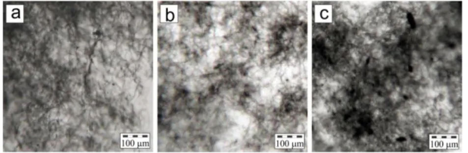
47 Figures 1.5a-b-c showed optical microscopy images of 0.2, 0.5 and 0.8 wt.% of CNT in PLLA respectively. Because of strong intrinsic van der Waals forces, individual carbon nanotubes are interwoven with each other, forming the interconnected network within the host material. In general, nanotubes are fairly dispersed across the matrix. Figure 1.5 also gives qualitative information on the nanotubes distribution in the films. Bigger black spots were observed in the image of 1.5.b and c. These observations clearly indicate that the agglomeration process of nanotubes in the composite is concentration-dependent.
Figure 1.5: Result of microscope image for PLLA composite with (a) 0.2 wt.%, (b) 0.5 wt.% and (c) 0.8%.
These observations agree well with former results on carbon black particles in the PLLA matrix [Kim 2007, Kuan 2008]. Kim et al. showed that the application of low shear forces could induce agglomeration of initially well-dispersed carbon black particles, explaining that the shear forces provide the particles with sufficient kinetic energy to overcome the repulsive interactions of the electric double layers. At the same time, agglomerates can be disrupted by high shear forces. Therefore, the cast
48 films also showed uniformly distribution of CNT within polymer matrix in polymer scale.
Figure 1.6: Result of microscope image for composite with 0.5 wt.% CNT in the different polymer matrix: (a) PLLA, (b) PCL and (c) PLGA
As described above, the CNT-PLGA solutions tend to heavily aggregate in the 0.8 wt% addition of CNT. On the other hand, at the same blend composition, PLLA and PCL solutions were still showing good dispersion. Figurer 1.6 depicted the images of cast film at concentration of 0.5 wt.% CNT in different host polymer. All the parameters were alike. It is hard to distinguish the dispersion quality of CNT between figure 1.6a and b or between PLLA and PCL matrices. On the contrary, a strong indication of more massive aggregation was sighted in the PLGA matrix (figure 1.6.c). Apparently, there is an equilibrium size for the nuclei of aggregated nanotubes. Obviously, this dimension is dependent on the concentration of CNT filler and also the solubility of CNT into the host polymer.
49 1.3.4 Tensile properties of composites
Due to their exceptional mechanical properties multiwall carbon nanotubes have been employed as reinforcing fillers for high-strength polymeric composites. In this context, various polymers have been used as matrix materials, and various cnt contents were employed. In general, the tensile moduli and ultimate strengths of CNT-based composites are reported to increase compared to neat polymer. The assessment of the data accumulated in numerous studies on carbon nanotube composites revealed that effective reinforcement of these materials strongly depends on several factors such as: a high aspect ratio of the CNTs, good dispersion of the nanotubes in a matrix, good interfacial bonding, interactions and mechanical anchoring between CNTs and polymer molecules. These simple design guidelines for carbon nanotube composites may permit substantial advances in the composites’ mechanical properties [Zhang etal 2003, Dalton etal 2003, Geng etal 2002, Velasco-Santos 2003].
The elastic modulus E and tensile strength T were evaluated from the
recorded stress-strain curves. The Young’s modulus was obtained by analysis of the elastic part of the stress-strain curve and calculated from [Feynman 1989]:
ε 1.5
where and indicate stress and strain in the elastic region of the stress-strain curve, respectively. F is the force applied to the sample, A0
50 specimen, while l0 is the original length of the sample. The ultimate
tensile strength was calculated using the equation:
1.6
where FMax is the maximum load prior to break and A is the cross-section
area of the sample.
The interfacial stress transfer remains the key issue for the efficient enhancement of the mechanical performance of the composites. The external load applied to the composite should be transferred to the nanotubes; therefore, only strong interconnections between CNTs and polymers may lead to the great mechanical improvement of heterostructures. This is the clue to fully utilise the outstanding mechanical performance of CNTs in a composite system.
The stress-strain curves of investigated films are given in figure 1.7. Plots show plateau area that would indicate a plastic deformation in the elastic part of the stress-strain curve. Two distinct elastic regions can be resolved in every graph and have been marked in figure 1.7a. These regions are related to the complex behaviour of the composite under external stress applied to the sample. Initially (region I) randomly orientated and curvy SWNTs tend to align along the stretching direction under the load. Consequently, the composite becomes more compact and SWNTs become more interwoven and knotted. Region II reflects the tensile properties of compact and packed composite with aligned and
51 tight nanotubes; the slope becomes much steeper than in region I, resulting in a higher value of the elastic modulus.
The tensile modulus (obtained from region II) and ultimate strength are: 65.2 ± 5.3 MPa, 2.1 ± 0.3 MPa, for the pure PLLA; and 223.8 ± 5.3 MPa, 6.3 ± 0.5 MPa, for a PLLA composite with 0.5% CNT content, respectively. The tensile strength of the neat polymers increased roughly around 3 times; the elastic modulus increased 3.6 times, when SWNTs were incorporated into the host material. These results show that the presence of carbon nanotubes is crucial for achieving improved mechanical properties of polymer composite.
52 Figure 1.7: Stress-strain profiles for (a) composite PLLA-CNT film and (b) comparative study of films with various concentration of CNT
53 As shown in table 1.3, PLLA films with SWNT content near to 1 wt.% were also investigated. The results show, as expected, a drastic decrease in the strength of the composites (figure 1.9.d). Young’s modulus and tensile strength are: 82.1 ± 10.6 MPa and 3.73 ± 1.7 MPa, respectively. This confirms that composites with greater agglomeration nanotubes are far weaker than films with finer blocks of SWNTs. The massive aggregation of carbon nanotubes apparently reduces the mechanical performance of composites due to the disruption of interfacial interaction between CNTs and polymer matrix.
It was also observed that increasing the loading amount of nanotubes in these composites caused a significant increase stiffness, which eventually led to brittle fracture, as indicated by lower elongation at break in tensile test. As can be seen in figure 1.7.b, the elongation at break of the composites slightly decreased from around 0.07 to 0.05 at CNT incorporation of 0.5 wt.% and 1.3 wt.%, respectively. Complete results for three polymers are summarised in table 1.3.
Table 1.3 presents the tensile strength and elastic modulus measured experimentally as a function of SWNT concentration for PLLA, PCL and PLGA. The mechanical properties of the spun films were essentially the same, suggesting that the three-dimensional distribution of nanotubes controlled the failure mechanism. The tensile analysis leads to the following observations:
Modulus increases with increasing SWNT concentration up to optimum CNT content then decreases. The optimum CNT additional content are 0.5 wt.% for PLLA and PLGA system. On the other hand, PCL system has value of 0.7 wt.%.
![Figure 1.1: Comparative mechanical property of bone and several materials in TE applications [Yuehuei 2000]](https://thumb-eu.123doks.com/thumbv2/123dokorg/7553372.109625/35.748.239.567.515.747/figure-comparative-mechanical-property-bone-materials-applications-yuehuei.webp)
![Figure 1.2: Schematic of CNTs/polymer nanocomposite with isotropic orientation of nanotubes [adapted from Du et al 2004]](https://thumb-eu.123doks.com/thumbv2/123dokorg/7553372.109625/40.748.186.515.401.654/figure-schematic-polymer-nanocomposite-isotropic-orientation-nanotubes-adapted.webp)