ALMA MATER STUDIORUM - UNIVERSITÀ DI BOLOGNA
School of Engineering and Architecture
Department of Civil, Chemical, Environmental and Material Engineering
(DICAM)
Campus Bologna
Second Cycle Degree in
ENVIRONMENTAL ENGINEERING
Master’s Degree Thesis in
"Systematic Investigation of Interoperability Issues between
Building Information Modelling and Building Energy Modelling"
Candidate
Supervisor:
Arghavan Akbarieh
Prof. Annarita Ferrante
Co-Supervisors:
Prof. Mohamed Hamdy
Prof. Giovanni Semprini
Dr. Simone Garagnani
Academic Year 2016/2017
Session III
Acknowledgment
“If I have seen further, it is by standing on the shoulders of giants.” _ Isaac Newton (1643-1727)
I hope that this thesis becomes a small part of the vast endeavors in addressing the BIM to BEM interoperability issues. Nevertheless, as well said by Newton, I could not have managed to finish this project without the help of many people that I had the pleasure to know them.
Therefore, I would like to thank my supervisors Prof. Mohamed Hamdy, and Prof. Annarita Ferrante, and Prof. Giovanni Semprini, and Dr. Simone Garagnani for giving me the opportunity to work on this interesting topic. I would especially like to thank Prof. Hamdy; without his patience, kind words, weekly meetings, edited manuscripts, guidance, and encouragements, this thesis would have been impossible. Similarly, the character and enthusiast of Prof. Ferrante has always warmed my heart and encouraged me. This thesis was a collaboration between the University of Bologna and The Norwegian University of Technology. Therefore, I would like to express my thankfulness for all the cooperations that have been made to make this collaborative research possible.
My absolute gratitude towards my parents and my brother, Aria, who helped me a lot during this thesis, is beyond the words. Without your love and support, I could not have come so far. Thank you for being a bright part of my life.
I also would like to thank my friends Hanne, Malin, Anette, Cecilia, Giovanni, and Paola for their kindness and deep understanding when I was working on the project day and night. I appreciate all the time you spent with me, even though sometimes short. Nevertheless, a special thank you goes to Afsaneh, Hooman, Sepideh, and Alla, for their moral support, fun video-clips, and cheer-up sessions. I hope to do the same for you soon.
There are numerous people, all around the world, who have responded to my questions in online forums with absolute agility, to you, I would send my warmest greetings.
Abstract
Integrated building design necessitates the Architecture-Engineering-Construction-Owner-Operator (AECOO) Industry’s participants to collaborate efficiently with each other through the different phases of a building. Nevertheless, to reduce the energy consumption and CO2 emissions of a building, the emphasis is on the early design phases, since if accurate energy calculations and strategies are developed in an early design stage, the sustainable footprint of the building will be significantly reduced.
That said, Building Information Modelling (BIM) promotes collaboration among the stakeholders by allowing them to design and store and access the data related to a project into one building information model. Furthermore, this model can be used for energy analysis through Building Energy Modelling (BEM) tools in the early design stages of the project, and through the whole life-cycle.
For this, BIM and BEM tools must be able to communicate and exchange information with one another, seamlessly. This means that these tools should be interoperable. However, currently, there are some issues in the BIM to BEM exchange process, which obliges the user to check for the interoperability issues and fix them manually. Therefore, as a result of these interoperability issues, the BIM to BEM process is not automated, and creating an accurate BIM-based BEM is quite time-consuming, laborious and prone to human-made errors.
Hence, this thesis aims to systematically investigate the interoperability issues and the state of automated data exchange between BIM and BEM tools, based on the Industry Foundation Class (IFC) exchange data schema. For this, Revit and IDA-ICE are used as BIM, and BEM tools, respectively.
The outcome is the presentation of a set of interoperability issues that were found based on the investigation of 19 case studies, with some suggestions for Revit and IDA-ICE developers and future researchers in the end.
Keywords:
BIM, Building Information Modelling, Revit, BEM, Building Energy Modelling, IDA-ICE, interoperability issues
Table of Contents
Acknowledgment ... i
Abstract ... ii
List of Figures ... vii
List of Tables ... xi
List of abbreviations ... xii
Chapter 1 Introduction ... 1
1.1 Motivation, Hypothesis, Aims, and Objectives ... 2
1.1.1 Motivation ... 2
1.1.2 Hypothesis ... 3
1.1.3 Aims, Objectives ... 3
1.2 Limitations ... 3
1.3 Methodology ... 3
1.4 Structure of the Report ... 6
Chapter 2 Literature Review ... 7
2.1 Review of Building Information Modelling (BIM) ... 7
2.2 Review of Building Energy Modelling (BEM) ... 11
2.3 Review of Interoperability ... 18
2.4 Review of Industry Foundation Classes (IFC) ... 20
2.4.1 Industry Foundation Classes (IFC) ... 22
2.4.2 Information Delivery Manuals (IDM) ... 26
2.4.3 BIM Collaboration Format (BCF) ... 26
2.4.4 Model View Definition (MVD) ... 26
2.4.5 International Framework for Dictionaries (IFD) ... 26
2.4.6 Classification of Space Boundaries in IFC schema ... 27
2.5 BIM-based BEM Interoperability Issues ... 27
Chapter 3 Methodology and Case-studies ... 28
3.1 Investigation of Revit ... 28
3.1.1 Introduction ... 28
3.1.2 Element Hierarchy in Revit ... 28
3.1.3 Element classes ... 30
3.1.3.1 Model Elements ... 30
3.1.3.3 Annotation Elements ... 31
3.1.4 Definitions of Room, Space, Zone concepts ... 31
3.1.4.1 Room ... 32
3.1.4.2 Space ... 32
3.1.4.3 Zone ... 33
3.1.5 IFC export in Revit ... 34
3.1.5.1 IFC exporter options ... 34
3.1.5.2 IFC exporter configuration for Energy Analysis purposes ... 43
3.1.5.3 List of supported IFC classes by Revit ... 47
3.2 Investigation of IDA-ICE... 48
3.2.1 Objects in IDA-ICE ... 48
3.2.1.1 Data Object ... 48
3.2.1.2 Hierarchy of Data objects ... 48
3.2.1.3 Comparison between Revit Element hierarchy and IDA-ICE Object hierarchy... 49
3.2.1.4 Geometry in IDA ICE ... 50
3.2.2 Mapping IFC data to IDA-ICE ... 57
3.2.2.1 Definition of Mapping ... 57
3.2.2.2 Step by Step guide to IFC mapping ICE by example ... 58
3.3 Case-Studies ... 65
3.3.1 Structure of Cases ... 65
3.3.1.1 Guide to the naming system of the Cases ... 65
3.3.1.2 Building Model ... 65
3.3.1.3 Task ... 66
3.3.1.4 Sub-Task ... 66
3.3.2 Description of the Building model ... 67
3.3.2.1 Building Model 1 (BESTEST Case 600) ... 67
3.3.2.2 Building Model 2 (BESTEST CASE 610) ... 69
3.3.2.3 Building Model 3 (BESTEST Case 620) ... 69
3.3.2.4 Building Model 4 (BESTEST Case 630) ... 69
3.3.3 Descriptions of Tasks and Sub-Task ... 70
3.3.3.1 Task 1 ... 70
3.3.3.2 Task 2 ... 71
3.3.3.4 Task 4 ... 72 3.3.3.5 Task 5 ... 72 3.3.3.6 Task 6 ... 72 3.3.3.7 Task 7 ... 73 3.3.3.8 Task 8 ... 73 3.3.4 Case-Studies ... 73 3.3.4.1 Case 01 ... 74 3.3.4.2 Case 02 ... 81 3.3.4.3 Case 03 ... 83 3.3.4.4 Case 04 ... 84 3.3.4.5 Case 05 ... 85 3.3.4.6 Case 06 ... 86 3.3.4.7 Case 07 ... 88 3.3.4.8 Case 08 ... 90 3.3.4.9 Case 09 ... 90 3.3.4.10 Case 10 ... 92 3.3.4.11 Case 11 ... 94 3.3.4.12 Case 12 ... 95 3.3.4.13 Case 13 ... 97 3.3.4.14 Case 14 ... 104 3.3.4.15 Case 15 ... 109 3.3.4.16 Case 16 ... 113 3.3.4.17 Case 17 ... 114
3.3.4.18 Case 18 and Case 19 ... 118
Chapter 4 Conclusions and Future Works ... 125
4.1 Summary ... 125
4.2 Conclusion Remarks and Suggestions ... 125
4.3 Future works ... 128
References ... 130
A. Appendix A. ... 138
A.1 Introduction to IDA ICE interface: ... 138
A.2 An overview of Standard Level ... 138
A.4 An overview of Floor plan tab ... 139
A.5 An overview of 3D view ... 140
A.6 An overview of Simulation tab, Summary tab, and Details tab ... 141
B. Appendix B ... 143
B.1 Room Properties ... 143
B.2 Space Properties ... 144
B.3 Zone Properties ... 147
List of Figures
Figure 1-1 An overview of the project ... 3
Figure 1-2 Methodology in one glance ... 4
Figure 2-1 BIM through the building life-cycle [17] ... 7
Figure 2-2 The 8 Dimensions of BIM ... 8
Figure 2-3 BIM technology and associated processes can help to respond to the increasing pressures on a building over its lifecycle [3]. ... 9
Figure 2-4 BIM promotes collaboration between various AECOO participants. ... 9
Figure 2-5 Levels of BIM [23] ... 10
Figure 2-6 BIM inputs ... 11
Figure 2-7 Inputs for BEM tools [33, 34] ... 12
Figure 2-8 Architectural view vs. Thermal view [37] ... 13
Figure 2-9 1st Spaces boundaries [38] ... 15
Figure 2-10 2nd, 3rd, and 4th Spaces boundaries [38] ... 16
Figure 2-11 5th Spaces boundaries [38] ... 16
Figure 2-12 Ideal BIM-based BEM workflow [34] ... 17
Figure 2-13 KISS (Knowledge Industry Survival Strategy) interoperability classification levels [20] ... 19
Figure 2-14 BIM to BEM process is one directional ... 20
Figure 2-15 Modern Exchange formats [3]. ... 21
Figure 2-16 History of IFC releases [69] ... 23
Figure 2-17 IFC2x3 Data schema architecture with conceptual layers [70, 71] ... 24
Figure 2-18 An example of the IFC structure for defining a wall [3] ... 25
Figure 2-19 An example of Inheritance graph for IfcWallStandardCase IFC class [73] ... 25
Figure 2-20 Interaction of IFC, IFD, IDM, and MVD in the middle [64, 65, 82] ... 27
Figure 3-1 An example of Revit’s element hierarchy [89] ... 28
Figure 3-2 Revit’s element hierarchy [90] ... 29
Figure 3-3 Element hierarchy inside Revit [90] ... 29
Figure 3-4 Revit’s Element classes [90] ... 30
Figure 3-5 Revit’s Model Element visualization [90] ... 30
Figure 3-6 Revit’s Datum Element visualization [90] ... 31
Figure 3-7 Revit’s Annotation Element visualization [90] ... 31
Figure 3-8 Room and Room Tag elements inside Revit ... 32
Figure 3-9 Space and Space Tag elements inside Revit ... 33
Figure 3-10 IFC explorer ... 35
Figure 3-11 IFC exporter Modify setup window, In Session Setup (1), and Creating customized Set-up (2) ... 35
Figure 3-12 IFC exporter Modify setup window, General tab ... 36
Figure 3-13 IFC exporter Modify setup window, IFC version ... 36
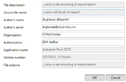
Figure 3-14 IFC exporter Modify setup window, General tab, File Header Information … ... 37
Figure 3-15 How File Header Information is exported to IFC file. ... 37
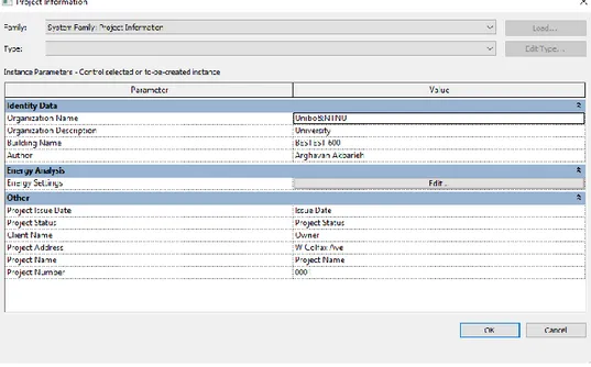
Figure 3-16 IFC exporter Modify setup window, General tab, Project Address… ... 38
Figure 3-17 How Project Address is written into other sections of Revit... 38
Figure 3-18 How Project Address is exported to IFC file ... 39
Figure 3-20 IFC exporter Modify setup window, Property Sets tab ... 40
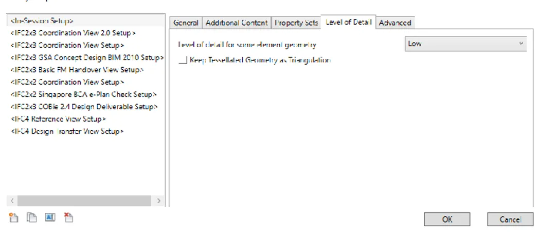
Figure 3-21 IFC exporter Modify setup window, Level of Detail tab ... 41
Figure 3-22 IFC exporter Modify setup window, Advanced tab ... 42
Figure 3-23 IFC Exporter in Revit ... 44
Figure 3-24 IFC Exporter in Revit, Modify Set-up... 44
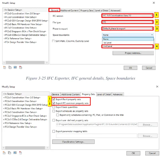
Figure 3-25 IFC Exporter, IFC general details, Space boundaries ... 45
Figure 3-26 IFC Exporter, IFC Property Sets configuration for Energy Analysis Purposes ... 45
Figure 3-27 Building System in IDA-ICE ... 51
Figure 3-28 Zone System in IDA-ICE [107] ... 51
Figure 3-29 Surface System in IDA-ICE [107] ... 52
Figure 3-30 Surface System in IDA-ICE for Wall object [107] ... 52
Figure 3-31 Construction definition in IDA-ICE [107] ... 53
Figure 3-32 IDA-ICE Zone ... 55
Figure 3-33 Active Zone in IDA-ICE, the zone has been assigned to IfcSpace ... 55
Figure 3-34 Importing IFC into IDA-ICE ... 58
Figure 3-35 Mapping in IDA-ICE ... 59
Figure 3-36 Mapping IFC data to IDA resources, Category: Materials (step one) ... 60
Figure 3-37 Material properties in IDA-ICE, to create or modify new materials ... 60
Figure 3-38 Mapping IFC data to IDA resources, Category: Materials (step three) ... 61
Figure 3-39 Material resources available in IDA database, IDA-ICE ... 61
Figure 3-40 Mapping IFC data to IDA resources, Category: Constructions ... 62
Figure 3-41 Construction resources available in IDA database, IDA-ICE ... 62
Figure 3-42 Window Mapping in IDA-ICE, creating a new detailed window ... 63
Figure 3-43 Detailed Window General tab(Left), Detailed Window Geometry (Upper Right), Glazing resources in IDA-ICE (Down Right) ... 63
Figure 3-44 Assigning constructions to surfaces ... 64
Figure 3-45 Building Models’ in one view ... 65
Figure 3-46 BESTEST Case 600 geometrical view [113] ... 67
Figure 3-47 BESTEST Case 610 geometrical view [113] ... 69
Figure 3-48 BESTEST Case 620 geometrical view [113] ... 69
Figure 3-49 BESTEST Case 630 geometrical view [113] ... 70
Figure 3-50 Visualization of the six different wall Location Lines in Revit [121]. ... 75
Figure 3-51 plan view of the Building Model 1 (Case 01) ... 76
Figure 3-52 Location Line, Properties palette, and wall centerline (Case 01) ... 76
Figure 3-53 Thickness of the wall in Revit ... 77
Figure 3-54 Building body in IDA-ICE (Case 01)... 78
Figure 3-55 Zone in IDA-ICE (Case 01) ... 78
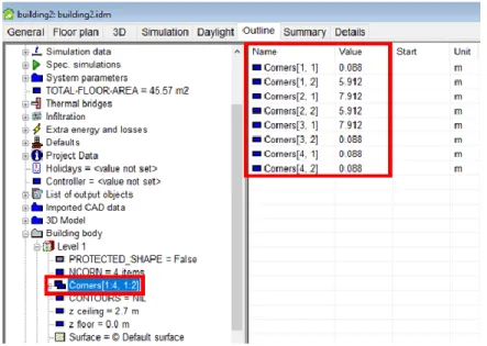
Figure 3-56 Corners of building model in IDA-ICE (Case 01) ... 79
Figure 3-57 Corners of the zone in IDA-ICE (Case 01) ... 79
Figure 3-58 Location Line in IFC ... 80
Figure 3-59 IFC Exporter setting, Export base quantities option ... 80
Figure 3-60 Quantities exported to IFC via “Export base quantities.” ... 81
Figure 3-61 Location Line, Properties palette, and wall Core centerline (Case 02) ... 82
Figure 3-63 Zone in IDA-ICE (Case 02) ... 83
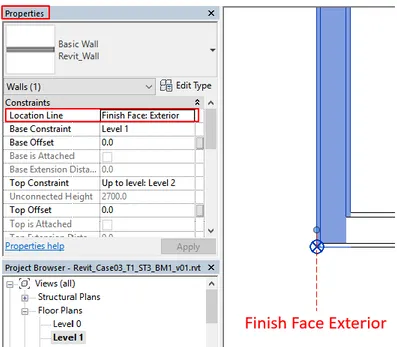
Figure 3-64 Location Line, Properties palette, and wall Finish Face: Exterior (Case 03) ... 84
Figure 3-65 Location Line, Properties palette, and wall Core Face: Interior (Case 04) ... 85
Figure 3-66 Plan view of the Building Model 1 without Room or Space elements (Case 05) ... 86
Figure 3-67 Room Properties, Defining Upper Limit, and Limit Offset ... 87
Figure 3-68 Plan view of the Building Model 1 with Room element (Case 06) ... 87
Figure 3-69 IFC file, IfcSpace, Revit’s Room element ... 88
Figure 3-70 IFC file, IfcPropertySingleValue ... 88
Figure 3-71 Plan view of the Building Model 1 with Space element (Case 07) ... 89
Figure 3-72 IFC file, IfcSpace, Revit’s Space element ... 89
Figure 3-73 plan view of the Building Model 1 with both Revit’s Room and Space elements (Case 08) . 91 Figure 3-74 IDA-ICE interface, Automatic Zone assignment to the enclosed geometry (Case 09) ... 91
Figure 3-75 IFC file, IfcSpace, Revit’s Room and Space elements are written into separate IfcSpace records ... 92
Figure 3-76 IFC file, IfcZone (Case 10) ... 93
Figure 3-77 Revit Interface, Zone ... 93
Figure 3-78 Space height is higher than wall height, IDA-ICE (Case 11) ... 95
Figure 3-79 zone height in IDA-ICE, Space/Room height is considered as to ceiling height (Case 11) .... 95
Figure 3-80 Room height is higher than Space height, Solibri Model Viewer (Case 12) ... 96
Figure 3-81 Thermal properties of the material Wood in the wall, BESTEST 600, Building Model 1 ... 98
Figure 3-82 Thermal properties of the whole wall, BESTEST 600, Building Model 1 ... 98
Figure 3-83 IFC Exporter, Export IFC common property sets ... 99
Figure 3-84 IFC Exporter, Export IFC common property sets, and Export Revit Property sets ... 99
Figure 3-85 IFC file, no thermal properties related to the wall was found in the IFC file, trial 1 ... 100
Figure 3-86 IFC file, some thermal properties related to the wall was found in the IFC file, trial 2 ... 100
Figure 3-87 Analytical Properties of wall element, Revit ... 100
Figure 3-88 IFC file, IfcSurfaceStyle, and IfcMaterial ... 101
Figure 3-89 IFC file, IfcMaterialLayer ... 101
Figure 3-90 IFC file, IfcQuantityLength ... 102
Figure 3-91 IDA-ICE Mapping IFC data to IDA resources window, Thickness of elements are derived from IFC data ... 102
Figure 3-92 IDA-ICE Mapping IFC data to IDA resources window, Thickness of materials are not derived from IFC data ... 103
Figure 3-93 Building Model 1 in Revit, Windows on the south Façade, 3D view ... 105
Figure 3-94 Building Model 1 in Revit, Windows on the south Façade, South Elevation view ... 105
Figure 3-95 Window properties inside Revit, Dimensions, and Analytical Properties of the Windows (Case 14) ... 106
Figure 3-96 Glass thermal properties inside Revit ... 106
Figure 3-97 IDA-ICE, windows geometry ... 107
Figure 3-98 IDA-ICE, windows properties, glass, and frame properties ... 107
Figure 3-99 IFC file, IfcSurfaceStyle storing information about glass type and sash material ... 108
Figure 3-100 IFC file, IfcWindow, IfcMaterialList, IfcProprtySingleValue ... 108
Figure 3-101 Window properties inserted into the new window family in Revit (Case 15) ... 110
Figure 3-104 Window mapping inside IDA-ICE (Case 15) ... 111
Figure 3-105 Simulation results of the Case 14, Building Model with built-in window family (Case 14) ... 112
Figure 3-106 Simulation results of the Case 15, Building Model with user-built window family (Case 15) ... 112
Figure 3-107 Orientation in Case 16 in Revit ... 113
Figure 3-108 Orientation in Case 16 in IDA-ICE ... 113
Figure 3-109 IFC file, IfcDirection ... 114
Figure 3-110 Visibility/Graphic window in Revit, Project Base Point ... 115
Figure 3-111 Coordinates of (0,0,0) point in IDA-ICE (left), and in Revit (right) ... 115
Figure 3-112 IFC file, How coordinates are exported to IFC? ... 115
Figure 3-113 Except Case 19, all the cases have a corner that is on the Project Base Point and (0,0,0,) coordinates. ... 116
Figure 3-114 change of coordinates of the Revit model (Case 19) ... 116
Figure 3-115 Zone in IDA-ICE (Case 18) ... 117
Figure 3-116 Building body in IDA-ICE (Case 18)... 117
Figure 3-117 Building Model 2, horizontal shading (Case 18) ... 118
Figure 3-118 Building Model 4, horizontal shading, and vertical fins (Case 19) ... 119
Figure 3-119 Creating new subcategory (1), overwriting the subcategory’s IFC with the desire IFC class (2) in Revit ... 119
Figure 3-120 IFC options in Revit ... 120
Figure 3-121 Creating IfcExportAs and IfcExportType in Revit ... 120
Figure 3-122 Building Model 2, Shading object geometry in IDA-ICE (Case 18.a) ... 121
Figure 3-123 Building Model 2, Shading object is not present in the thermal zone in IDA-ICE (Case 18.a) ... 121
Figure 3-124 Creating External Horizontal Shading in IDA-ICE (Case 18.b) ... 122
Figure 3-125 External Horizontal Shading, created inside IDA-ICE (Case 18.b) ... 122
Figure 3-126 Building Model 1 (Case 14) ... 123
Figure 3-127 Simulation A (Building Model 1, Case 14) ... 124
Figure 3-128 Simulation B (Building Model 2 with IfcShadingDevice, Case 18.a) ... 124
Figure 3-129 Simulation C (Building Model 2 with shading created in IDA-ICE tool, Case 18.b) ... 124
Figure A-1 IDA-ICE interface, Standard level, General tab [108] ... 138
Figure A-2 IDA-ICE interface, General tab [108] ... 140
Figure A-3 IDA-ICE interface, Standard level, General tab [108] ... 140
Figure A-4 IDA-ICE interface, Standard level, 3D tab [108] ... 141
Figure A-5 IDA-ICE interface, Standard level, Simulation tab [108] ... 141
Figure A-6 IDA-ICE interface, Standard level, Summary tab [108] ... 142
List of Tables
Table 1-1 Structure of Case studies, and interoperability issues ... 5
Table 1-2 The outline of the thesis structure ... 6
Table 2-1 Five open standards of BuildingSMART [64]... 22
Table 2-2 IFC classification type for space boundary levels ... 27
Table 3-1 Explanations about IFC Mapping Drop-down window [108] ... 58
Table 3-2 Explanations about Mapping IFC data to IDA resources [108] ... 59
Table 3-3 Abbreviations used for systematic reference naming ... 65
Table 3-4 Building models’ abbreviations and descriptions ... 65
Table 3-5 Task’s abbreviations and descriptions ... 66
Table 3-6 Overview of case-studies and Sub-Tasks’ abbreviations and descriptions ... 66
Table 3-7 BESTEST Case 600’s wall material description [113] ... 67
Table 3-8 BESTEST Case 600’s floor material description [113] ... 67
Table 3-9 BESTEST Case 600’s roof material description [113] ... 67
Table 3-10 BESTEST Case 600’s window description [113] ... 68
Table 3-11 Overview of all the Tasks ... 70
Table 3-12 Overview of the Sub-Tasks of Task 1 ... 71
Table 3-13 Overview of the Sub-Tasks of Task 2 ... 71
Table 3-14 Overview of the Sub-Tasks of Task 3 ... 72
Table 3-15 Overview of the Sub-Tasks of Task 4 ... 72
Table 3-16 Overview of the Sub-Tasks of Task 5 ... 72
Table 3-17 Overview of the Sub-Tasks of Task 6 ... 73
Table 3-18 Overview of the Sub-Tasks of Task 7 ... 73
Table 3-19 Overview of the Sub-Tasks of Task 8 ... 73
Table 3-20 Overview of cases and the Systematic Reference naming ... 74
Table B-1 Room Properties in Revit ... 144
Table B-B-2 Space Properties in Revit ... 147
Table B-3 Zone Properties in Revit ... 149
List of abbreviations
Abbreviation Complete name
IFC2x3 IFC2x Edition 3
BCF BIM Collaboration Format
AEC Architecture, Engineering, and Construction
AECOO Architecture-Engineering-Construction-Owner-Operator
BEM Building Energy Modelling
BIM Building Information Modelling
BPS Building Performance Simulation
CAD Computer-Aided Design
FM Facility Management
IAI International Alliance for Interoperability
ICT Information Communication Technology
IDA-ICE IDA Indoor Climate and Energy
IDM Information Delivery Manual
IDP Integrated Design Process
IFC Industry Foundation Class
IFD International Framework for Dictionaries
STEP Standard for the Exchange of Product Model Data
Chapter 1 Introduction
The increasing attention to improving the energy efficiency in the built-environment has brought to spotlight the Building Information Modelling (BIM) due to its potential for integration with Energy Analysis and Simulation tools. BIM is a methodology to digitally construct an architectural model that holds detailed multi-disciplinary information regarding the spatial information, thermal values, material properties, schedules, etc. through the life-cycle of the building [1-3]. The Building Information Model (we call it BIM model in this report) can be then exchanged with other software for further analysis, for instance for energy analysis, structural analysis, and so on.
In contrary to popular belief, although building information modelling has become much more straight-forward and sophisticated than the traditional 2D plans, but energy modelling software is unable to read the information coming from a BIM-based model fully, and thus are not able to analyse the energy performance of the building as it is. Hence, a manual procedure is required to either, remodel the desired building in Building Energy Modelling (BEM) tools, or to correct the wrongly-translated building information. This problem is known as interoperability issue. Indeed, “Interoperability” is the ability of two tools to communicate and exchange data that is readable for both correctly. Currently, this process is highly time and labor consuming as well as being quite error-prone, and it requires more attention [3, 4].
The BIM to BEM process consists of three parts BIM tool, model schema exchange format, and BEM tool. Interoperability issues can arise from either of these parts and are not necessarily limited to the ability of BEM tools to read the input information.
Therefore, this project was defined to investigate the potentials and difficulties of energy performance modelling and analysis using BIM to BEM methodology with having an eye on the possible solutions for the current challenges of the interoperability in BIM to BEM tools through this case study.
The first step consists of undertaking a state-of-the-art review to answer the following questions. What have other researchers suggested as main reasons behind the interoperability issue in BIM to BEM procedure? How previous case-studies have overcome interoperability challenges and are their solutions reproducible for other building types?
In the second step, BIM and BEM software will be investigated to identify the most suitable tools for results’ visualization and simulation analysis. It is extremely likely for Autodesk©Revit to be used for BIM modelling due to its position as the most prevailing BIM authoring tool in the market.
Afterward, based on the preceding step, the simulation will be executed on the BIM-based model to obtain the energy performance of the building and render solutions for improving the performance through best solution packages with respect to the climatic conditions. In other words, this step will help to study several alternatives in order to choose the cost-optimal solution as recommended by the Energy Performance of Buildings Directive 2010/31/EU (EPBD Recast) [5].
The final stage of the study comprises of investigating interoperability issues found in BIM to BEM procedure and addressing it while utilizing previously suggested methods or ad-hoc solutions tailored to this specific building. Figure 5 visualizes the methodology.
1.1 Motivation, Hypothesis, Aims, and Objectives
1.1.1 Motivation
Building Information Modelling (BIM) is a methodology that creates Building Information Models which are a digital representation of physical and functional characteristics of a building. BIM models are able to store geometric, semantic and topological information for the whole life-cycle of a building. This provides an effective bed for all participants of the Architecture-Engineering-Construction-Owner-Operator (AECOO) Industry to gather their efforts and information in one model, BIM. In fact, all partners can collaborate whit each other, and access all the information only through one building information model. This is why BIM has revolutionized the AECOO community. Because it reduces time, effort, cost, error, and confusion for individuals and companies.
Furthermore, it is possible to export the BIM model to other tools for further analysis in other domains. For instance, for energy analysis in Building Energy Modelling (BEM) tools. In order to exchange the BIM model to other tools, it should be exported to digital data structures (called data model or data schema) that are commonly accepted between other industry tools. Industry Foundation Classes (IFC) are an international open file format that is supported by various tools across many engineering disciplines. IFC is developed by BuildingSMART and has several releases. The most common release is IFC2x3 which is used in the project. The lasts release is IFC 4.
Many Building Energy Modelling (BEM) tools are capable of importing and reading the IFC file format. However, the flow of information from BIM to BEM is not automated. There are many issues that are related to either the BIM tool, the given data exchange format, and the BEM tool. Due to these issues, the tools are not able to communicate with each other seamlessly. Sometimes, after the exchange of the model to the second tool, some information is lost, objects are missing, objects are in wrong positions, and with wrong colors, elements are duplicated, or not transferred at all, and so forth. This is called interoperability issue. In fact, interoperability is the ability of two tools to exchange information or model without losing any information in between.
Despite the great potentials of BIM and BEM tools, the existing interoperability issues have made it quite difficult for experts to use BIM as the basis for their BEM model. Because finding and fixing the issues is rather time-consuming, laborious, and prone to human mistakes. That said, since the interoperability issues vary between the tools and are dependent on the type of information being exchanges, the results of one BEM modeler is not necessarily reproducible by others. This has greatly diminished the popularity of BIM-based BEM.
Therefore, to map the interoperability issues between BIM to BEM tools, we investigated 19 case-studies through a systematic approach. Our goal was to understand the Interoperability Issues that we anticipated to encounter during the cases. The building model that was used during the investigations is called BESTEST 600. The BESTEST 600 building is used in the validation of building energy simulation programs and is an internationally-recognized model. Moreover, our BIM tool was Revit which is a quite popular, and market-dominant tool for Building Information Modelling. The BEM tool used in our investigation is called IDA-ICE which is a powerful tool for energy simulation and analysis of a building, albeit it is commercial. The exchange data format between these two tools was IFC.
1.1.2 Hypothesis
This thesis hypothesizes that there exist interoperability issues between the exchange of information between BIM and BEM tools that prohibit the automated energy modelling from an architectural model.
1.1.3 Aims, Objectives
The primary aim of this thesis is to improve the computationally-aided-energy-analysis process in the building sector by investigating the interoperability issues between BIM and BEM tools and to facilitate sustainable and integrated design. This shall lead to the following objectives:
o Review of the state-of-the-art of BIM, BEM, IFC, and related interoperability issues in the literature,
o Review of the BIM, and BEM tools (here: Revit and IDA-ICE, respectively), and their related terminology, concepts, and definitions
o Develop building information model of the case studies,
o Find interoperability issues in the exchange process of the building model form BIM to BEM, o Propose solutions and create a framework for the interoperability issues to assist future BIM-based
energy modeling and CAD companies.
1.2 Limitations
One of the limitations of this study was the lack of proper guidelines for exporting IFC from Revit, for the purpose of energy analysis. Another limitation is the software-based terminology and object hierarchy that is specific to each company. This has hugely impacted the interpretations of how different software approach one building element, e.g., a wall. In Section 3.2.1.3 we tried to compare how Revit’s element hierarchy matches IDA-ICE’s object hierarchy, but in the end, we noticed that such comparison might not be very valid.
1.3 Methodology
A case study approach is adopted to help understand the deficiencies and potentials of energy performance modelling and analysis using BIM to BEM methodology with particular attention to possible solutions for the existing interoperability challenges. Figure 1-1 shows the workflow of performing each case study. First, the BIM model is created in the Revit. Then, it is exported as IFC file. And finally, it is exported to IDA-ICE. At each stage, the model was explored for the interoperability issues. Figure 1-2 presents an overview of the methodology of this thesis, and Table 1-1 elaborates the case studies and the interoperability issues under investigation. The methodology and case-studies are presented in Chapter 3.
Figure 1-2 Methodology in one glance
Literature Review
• Building Information Modelling (BIM).
• Building Energy Modelling (BEM).
• BIM to BEM Interoprability interoprabiltiy issues in
construction sector.
• Industry Foundation Classes (IFC).
Building
Information
Modeling
• Investigation of the BIM authoring Tool (Revit).
• Model the building base on case-study's requirement.
• Export model as IFC format.
• Investigation of how each case-study is exported to IFC
classes.
Building Energy
Modeling
• Investigate of the Building Energy Modelling tool (IDA-ICE).
• Import model from BIM to BEM.
• Find the missing data, redundancies, interoprability issues.
• Run Simulations.
Results and
Conclusions
• present the interoperability issues found in the case-studies.
• present the suggestions for the software companies:
AutoDesk (Developer of Revit) and EQUA Simulation AB(
Developer of IDA-ICE)
Interoperability Issue under investigation Task Sub-Task
Sub-Task Description
1. Can Revit export Location line type of the walls to IFC?
2. Does the Location line type influence the imported geometry of the building inside IDA-ICE? 3.
1
Wall Location LineST1 Wall Centerline (default) ST2 Core Centerline
ST3 Finish Face: Exterior & Finish Face: Interior
ST4 Core Face: Exterior & Core Face: Interior
4. How the placement of different 3D spatial element components (i.e., Room, Space, and Zone) in BIM affects the IFC file and the BEM model?
5.
2
Zone vs Space vs
Room
ST1 No Room, Space, or Zone element ST2 Room
ST3 Space ST4 Zone
ST5 Room + Space ST6 Room + Space + Zone
6. How variation of geometrical properties of Room and Space in Revit affect the BIM-based energy modelling in IDA-ICE? 7.
3
Space/Zone height vs. Wall heightST1 Space height = Room height ST2 Space height ≠ Room height
8. How materials’ properties are exported from Revit to IDA-ICE?
9. How are they stored in the IFC data schema?
10.
4
Materials
ST1 Material’s thermophysical properties
11. How windows’ geometry and properties are exchanged Between Revit and IDA-ICE?
12. How is a user-built window family in Revit exported to IFC?
13. Can IDA-ICE recognize a user-built window family made in Revit?
14. What are the differences between Built-in Families, and user-built families Built-in Revit to IDA-ICE procedure?
15.
5
Windows
ST1 Revit built-in windows with built-in Analytical construction
ST2 Revit new family created from scratch window
16. Does IDA-ICE recognize the orientation of the BIM model and its components? 17. How are the changes of the orientation
of building elements in Revit reflected in IDA ICE?
18.
6
Orientation
ST1 Building orientation
ST2 Change of building orientation of BM_1 from N_S direction to 30◦ NE
19. How does Revit export coordinates to IFC file?
20. How does IDA-ICE interpret the coordinates from an incoming BIM model through an IFC file?
7
Coordinates
ST1 Coordinates of elements
21. How shadings and fins are created in
Revit and exported to IFC?
22. How does IDA-ICE understand the shadings in the BIM model?
8
Shading
ST1 Horizontal shading (South façade) BM_2
ST2 Horizontal and vertical shading (E/W facade) BM_4
1.4 Structure of the Report
This report is organized into four chapters that are described in the following line. Additionally, Table 1-2 demonstrates an outline of the thesis structure.
Chapter 1: Introduction
In this chapter, a general overview of the thesis is presented, along with aim, objectives, and limitations of the work.
Chapter 2: Literature Review
In this chapter, a theoretical background to Building Information Modelling (BIM), Building Energy Modelling (BEM), Interoperability, Industry Foundation Classes (IFC), is presented.
Chapter 3: Methodology and Case-studies
In this chapter, firstly, a brief introduction to the software of choice, i.e., Revit (for Building Information Modelling), and IDA-ICE (for Building Energy Modelling) is delivered. Afterward, case-studies are introduced and explained in detail.
Chapter 4: Conclusions and Future Works
In this chapter, the conclusions that were made based on the case-studies’ results are summarized and reported. Based on these conclusions, some ideas for future researchers are presented. Eventually, some suggestions are offered to the software companies that have developed Revit, and IDA-ICE.
Chapter Title Summary Questions to be addressed
1 Introduction Present hypothesis, aims and objectives, research questions, and the research methodology. 2 Literature Review Review BIM, BEM, IFC,
and interoperability issues.
What is BIM? What is BEM? What is IFC, and how it stores the information? What are the interoperability issues in the BIM to BEM processes?
3 Methodology and
Case-studies
A brief overview of Revit and IDA-ICE’s concepts. Presentation of case-studies, and their results.
What are the interoperability issues in Revit to IDA-ICE process? What are the capabilities of Industry Foundation Classes?
4 Conclusion Summary of findings,
suggestions, and future works.
What are the possible solutions to resolve the interoperability issues found in Chapter 3? What are possible next steps for future works?
Chapter 2 Literature Review
This chapter begins with an overview of Building Information Modelling (BIM) in Section 2.1; it is then followed by a review of Building Energy Modelling (BEM) in Section 2.2. Afterward, the interoperability is discussed in Section 2.3, which leads to an overview of Industry Foundation Classes (IFC) in Section 2.4.
2.1 Review of Building Information Modelling (BIM)
The term “BIM” was first used by AutoDesk staff [6]. However, Jerry Laiserin is known as the first person who publicized this term in the Industry [7]. The early definition of BIM varies; Bazjanac defines BIM as a “noun” which describes “ an instance of the populated data model of building” that holds multi-disciplinary “raw data” for a particular building [6]. Furthermore, Eastman [3] defines BIM as “a modeling technology and associated set of processes to produce, communicate, and analyze building models.” In other definitions, BIM “is a digital representation of physical and functional characteristics of a facility that offers potentials for life cycle modelling and management of the building or its systems” [8], and “is a methodology to manage the essential building design and project data n digital format throughout the building life-cycle” [9]. Additionally, BIM used to be referred to as Building Product Modelling, or product models, that are object-oriented. They contain data-rich building components, 3D geometrics, spatial information, thermal values, and material properties. These are the properties upon which data interoperability is built [2].
Many BIM professionals agree that BIM is an object-oriented digital representation of a building or built environment that enables the data exchange in digital form. BIM can attribute both spatial and geometrical as well as non-geometrical attributes to building elements to be implemented in the various areas of AEC, such as fire protection, safety on construction site, facility management, structural analysis, daylight simulation, construction management, cost-estimation and planning [1, 2, 10-15]. BuildingSMART considers building information model as a shared knowledge resource for information about a facility forming a reliable basis for decisions during its life-cycle (from earliest conception to demolition) [16]. Figure 2-1 shows BIM and the lifecycle of the building.
Likewise, “BIM is an information-rich building model that allows the thermal, structural, or cost-analysis to be carried out, based on one building model.” This definition introduces the different dimensions of a Building Information Model [2, 18] that can be seen in Figure 2-2.
Figure 2-2 The 8 Dimensions of BIM
Building Information Modeling has numerous benefits. BIM technology and associated processes are at the heart of how the building design and construction process responds to the growing pressures of higher complexity, faster development, improved sustainability while reducing the cost of the building and its subsequent use [3].
BIM is an enormous player in the future of construction sector [3]. McGraw Hill Construction reported in 2008, 45% of architects, engineers, contractors and building owners surveyed used BIM on 30% or more of their projects [19]. Although Architecture-Engineering-Construction (AEC) industry practitioners started to adopt BIM in their projects From mid-2000’s, It is anticipated that BIM grows sharply in the next coming years [20, 21]. Despite that, some argue that, currently, BIM is being slowly adopted in the industry, mainly because of lack of demand, cost and interoperability issues [22].
Even now, BIM and ICT have a brought a digital tornado in Architecture-Engineering-Construction-Owner-Operator (AECOO) Industry. There are many ongoing theoretical and practical projects that are investigating the Integration of BIM and other tools [21]. There are various participants in the industry that
3D
•Modelling
•An upgrade to the traditional CAD plans
4D
•Time
•Scheduling and construction stages simulation
5D
•Cost
•Planing and estimation
6D
•Sustainability Performance
•Thermal analysis and environmental assessment, eventually even automated building certification
7D
•Facility Management, Maintenance and Operation
•Fully mature and comprehensive model, ready to maintain and manage assets
8D
•Deconstruction
•The decommissioning, demolition, repurposing or recycling of a building or structure
demonstrates some of the significant collaborators on the BIM model. This collaboration brings many benefits for all parties, such as better interoperability capabilities, reduced conflict and project team benefits [22].
Figure 2-3 BIM technology and associated processes can help to respond to the increasing pressures on a building over its lifecycle [3].
Figure 2-4 BIM promotes collaboration between various AECOO participants.
In an interesting approach, Eastman has described what is not BIM in order to clarify this term even more [3]. According to him, four types of building models are not BIM.
I. Models that solely contain 3D data and no (or few) object attributes, II. Models that have no parametric intelligence,
III. Models that are composed of several 2D CAD reference files that must be combined to define the building,
One important thing to consider is that BIM is different with CAD (Computationally Architectural Design) [3]. CAD systems are becoming more intelligent day by day, which entices more users to share their data that is associated with a given design. This lead to a focus shifted from drawings and 3D images to the data itself. As a matter of fact, the key aspect that differentiates BIM from computer-aided design is the semantics A building model produced by a BIM tool includes 2D and 3D views along with the building model’s contents and capabilities [3].
Furthermore, BIM can be subdivided into two levels, Big BIM and Small BIM according to [23] based on the different needs of BIM in daily practices and different situations of BIM use. Figure 2-5 elaborates more on this differentiation.
Figure 2-5 Levels of BIM [23]
BIM authoring tools allow users to make a 3D information-rich digital model of a building. Such as: o Revit by AutoCAD [24],
o ArchiCAD by Graphisoft [25], o Tekla by Trimble [26],
o Allplan by Nemetschek [27], o Microstation by Bentley [28].
Depending on the choice of BIM tool, a significant number of inputs can be inserted into the model. Some of these inputs are illustrated in Figure 2-6.
The literature review about BIM is endless; with the increased implementation of BIM in academia and industry, the number of studies that are investigating the BIM definition, and adaptation in the AECOO industry is on the rise. The different dimensions and aspects of BIM, such as sustainability, are the focus of many studies [21, 29-32].
BIM
Building Information Modelling
Big
The use of BIM in collaboration with multiple (project) partners and tools.
Little
The use of BIM within a single company or with a single tool.
Figure 2-6 BIM inputs
2.2 Review of Building Energy Modelling (BEM)
Building Energy simulation tools are being used by the building design professionals more and more every day, since, from an AECOO perspective, advanced analysis of building energy simulation has become a critical part of the integrated design [33]. Energy performance simulation programs are robust tools to assess the energy performance and thermal comfort of a building over its whole life-cycle. However, these simulation tools differ in many ways regarding their:
o thermodynamic models, o graphical user interfaces, o purpose of use,
o life-cycle applicability,
o ability to exchange data with other software applications [34].
The term “Building Energy Simulation” tools are interchangeably used as “Building Performance Simulations” tools, and recently, they are also referred to as “Building Energy Modelling” tools, since this name resonates with Building Information Modelling tools. However, there is no significant
BIM
Metadata 3D Geometry Materials Schedules Site Information Occupancy Information Heating and Cooling Loads MEP Information Structural Elements Furniture Phase of Constructiondistinction in the literature regarding the usage of these names, and they are somewhat used by authors interchangeably. Here, in this study, we will refer to the tools that make energy simulations possible as Building Energy Modelling (BEM) tools.
In general, BEM, or BPS tools improve the understanding of how a given building operates according to certain criteria and enable comparisons of different design alternatives, with respect to its energy performance [34].
Figure 2-7 Inputs for BEM tools [33, 34]
While energy simulations could be applied in every stage of the building lifecycle, traditionally, energy performance simulation and analysis do not start until after some fundamental design decisions (such as architectural and HVAC design decisions) are made that affect the energy performance of the future building [1]. However, with the advancements of technologies in both BIM and BEM domain, there is a highlighted emphasis on the Integrated building design approaches and concepts such as Zero Energy Buildings that requires a more fluent process of energy modeling that directly leverage BIM-based thermal analyses during the design phase [35].
It can be said that today, not only in the building design phase but also in the operation phase, Building Energy Modelling tools are constantly being used by professionals. The accuracy of a thermal simulation model depends heavily on the accurate definition of building geometric characteristics, including the building envelope, the building orientation, the configuration of spaces, surfaces, and volumes [34, 36].
geometry, internal loads, HVAC systems and components, weather data, operating strategies and schedules, and simulation specific parameters [34].
Moreover, simulation engines contain mathematical and thermodynamic algorithms that are used to calculate the detailed energy performance according to the underlying model of the engine that can be simple text-based input and output files [34].
Building thermal simulation is the “dynamic analysis" of the energy performance of buildings using computer modeling and simulation techniques. In this simulation, a calculation of building thermal loads and thermal consumption is involved in determining the thermal characteristics of the building and its building systems. These calculations are necessary to promote sustainable built environment design and application and offers thermal comfort for the occupants. Building thermal simulation is a robust method for studying the thermal performance of buildings and to evaluate the architectural design in order to cut down the energy and carbon footprint of buildings form the design phase [33].
BEM tools, as well as many other types of simulation and analysis tools (such as acoustics and fire propagation simulation tools), have their own internal data models of building geometry. Such internal data models represent views of building geometry typically quite more straightforward than the geometry data models of CAD and BIM tools [34, 37]. Figure 2-8 illustrates this explanation clearly. Usually, architectural view of the building (the output of the CAD/BIM tools) is highly complex in terms of geometry and data, while the thermal view is quite simple in comparison.
Figure 2-8 Architectural view vs. Thermal view [37]
The term thermal view comes from the simplified model that is required for energy modelling, and is constructed based on the architectural model. The construction of thermal view depends of the person’s understanding of the subject building, his or her knowledge and skill, experience, complexity of the building
geometry of the subject building, complexity of the building itself, available resources, etc. Eventually, the result is not necessarily reproducible and is quite arbitrary: Different people defining the thermal view of the same building generates view definitions that differ from each other [1].
Space boundaries as one of the fundamental concept of building energy models (BEMs) that are necessary for the BIM to BEM model transfer. The space boundary works as a link for building geometry definitions between the architectural and thermal view, or BIM and BEM tools.
Most simulation and analysis tools define building geometry as systems of surfaces (i.e., surfaces that delineate walls, roofs, beams, windows, and doors) which are all part of the definition of spaces and/or zones identified in the model of the building. Such surfaces are called “space boundaries” [38].
Space boundaries come in “pairs:” One pair defines the inside, while the other defines the outside of a given surface. Exterior walls, slabs, roofs, windows, and doors are an exception; they solely have one space boundary that corresponds to their interior surface because of how BEM tools handle exterior surfaces since the exterior cannot be modeled as a space or a zone [38].
Space boundaries are flat polygons with an outward or inward normal which indicates the direction of transmission or flow through the given space boundary. According to Bazjanac [38], five levels of space boundaries can be found in a building:
o 1st level:
The 1st level space boundary is the whole surface of an element that bounds a space. In other words, a 1st level space boundary is the surface of a building element that is continuously visible from within a space or a zone by a person in that zone [38]. 1st level space boundary is shown in Figure 2-9.
1st level space boundaries are implemented in visualization tools to facilitate the showing of what the eye sees in a space or a zone. These tools do not consider transmission or (energy) flow through the modeled surfaces” [38].
o 2nd level:
For energy simulation purposes, space boundaries must be modeled in a more detailed manner, to take into account the different heat flows between spaces. If, for example, a wall separates one space on one side from two spaces on the other side, the 1st level boundary needs to be split up into two 2nd level boundaries [38]. If the 2nd level space boundary is interior, then it will come as “pair:” A pair is a space boundary of exactly the same shape and size, offset from the original 1st level space boundary by the thickness of the “parent” building element. This is shown by the color blue in Figure 2-10. If the viewer person stands in zone 1, the previous 1st level space boundary is subdivided into two segments which facilitate two different rates of transmission or flow. Each segment is a second (2nd) level space boundary.
“The definition and use of 2nd level space boundaries are mandatory in the use of tools that simulate the transmission or (energy) flow through the modeled interior surfaces. Windows, skylights, and doors, as well as virtual surfaces (e.g., simulated “air walls”) which constitute non-physical boundaries of zones, are also represented as 2nd level space boundary pairs in such simulation [38]”.
o 3rd level:
Not all parts of a 1st level boundary are translated to 2nd level boundaries; some parts will be 3rd level space boundary as shown by yellow in Figure 2-10. There is no space behind these parts, but a building element on the other side, therefore, these parts are considered as 3rd level space boundaries. This means that these surfaces do not play a role in the transmission or (energy) flow through the building element because there is no other zone to receive the perpendicular transmission or flow through these unaccounted surface areas [38]. Also, exterior building elements (roofs, exterior walls, and exterior slabs) do not have 3rd level space boundaries [38].
o 4th level:
4th level space boundaries display same behaviors as 3rd level space boundaries. In fact, depending on the BIM tool and the placement of wall reference lines (similar to Location lines in Revit), some areas can be left unaccounted for by 3rd level boundaries. 4th level space boundaries are shown by the color purple in Figure 2-10. As exterior walls, slabs and roofs can have only one surface in simulation tools’ internal data models. Thus, the exterior walls cannot include any 4th level space boundaries.
o 5th level:
When building elements intersect with each other at a non-right angle, another type of surfaces is formed that cannot be categorized in any other space boundaries. These areas called 5th level space boundaries have no perpendicular heat flow, shown by orange in Figure 2-11.
Figure 2-10 2nd, 3rd, and 4th Spaces boundaries [38]
Figure 2-11 5th Spaces boundaries [38]
Therefore, there are five levels of space boundaries that are needed for the use of building geometry representations by building energy simulation tools [38]. That said, today, many BEM tools are mainly based on one-dimensional heat transfer between thermal zones. This assumption simplifies the geometric input dramatically and allows shorter simulation run-times, despite the higher accuracy of simulation results of 2 or 3-dimensional heat transfer models [34]. This means that in most cases, only 1st level and 2nd level space boundaries are considered for building energy modelling.
That said, BEM tools require the availability of geometrical and material thermal data [39]. At first, geometrical information was obtained from CAD software that necessitates a manual process to generate the proper inputs for the thermal simulation software. This process is hugely error-prone and time-consuming. The advent of BIM resulted in a paradigm shift towards an object-centric view for the representation of building information and the availability of BIM as the geometrical input of BEM tools [3, 39] That said, Consequently, since BIM model has more information that it is necessary for BEM tools, BIM-based models must be transformed (i.e. simplified, reduced, translated or interpreted) before they can be directly used by BEM tools [37].
Although there has been a surge in the energy simulation services due to market drivers such as building rating systems, e.g., LEED, BREAAM, or programs such as EU 202020 goals, there has not been significant development beyond the use of standalone simulation tools by specialized practitioners who are more comfortable with manual building data input than automated data exchange through BIM to BEM [40]. Another reason could be that dominant BIM authoring vendors prefer to implementing embedded energy analysis tools within their flagship products rather than implementing robust data exchange with third-party tools that do not contribute to their revenue stream [40].
In many cases, While based on professional expertise, the process of BIM to BEM have a tendency to be uniquely performed by each expert based upon methods and rules-of-thumb developed over time by that individual [40]. This statement was observed during the period of this research as well. It seems that there are few experts who have profound practical knowledge of exact BIM to BEM process, and this knowledge is not really openly discussed on the internet, or in the literature.
As a result, BIM to BEM process is a non-standardized process that produces energybuilding energy models that varies fromone modeler to the next, even though the initialbuilding design information is the same for all modelers [40]
There could be different reasons for this non-standardized process. Firstly, there has been a traditional separation between architectural, energy simulation, and mechanical engineering professional disciplines before the advent of integrated building design. This is again referring to the dichotomy between an architectural view of a building and energy simulation, or thermal view of the same building according to [41]cited in [40] which in turn has impacted the standalone nature of software tools used by each of the participating design disciplines [40].
There is a growing number of environmental performance building analysis programs on the market; Bahar et al. [33] have reviewed the most applicable building thermal simulation tools in the AECOO community regarding their application, input data, output data, and BIM-based geometry import. That said, since 1996, more than four hundred building energy simulation tools have been listed in the “Building Energy Software Tools Directory” provided by U.S.DOE [42, 43]. Some of these tools are open-source, and others are commercial. Nevertheless, quite a handful of them is used in industry and academia. Some of these BEM tools are listed below:
o DesignBuilder by DesignBuilder [44],
o Ecotect eQUEST by
James J. Hirsch & Associates in collaboration with Lawrence Berkeley
National Laboratory [45],
o EnergyPlus by DOE, BOT, and NREL [46] o EcoDesigner by Graphisoft [47]
o ESP-r by the University of Strathclyde [48] o Green Building Studio by AutoDesk [49]
o IDA-ICE (IDA Indoor Climate and Energy) by EQUA Simulation AB [50],
o
VE (Virtual Environment) by IES (Integrated Environmental Solutions), known as
IES-VE [51],o TRACE 700 by Trane [52], o TRNSYS [53],
o Riuska by Granlund [54].
Some of these simulation tools can be plugged into BIM authoring tools as add-ins such as IESVE and Green Building Studio, which allow energy simulation within the BIM environment [43], while others require the BIM tool to provide a certain input for them, such as IDA-ICE, EnergyPlus, etc. Nevertheless, to link Building Information Modeling (BIM) tools and energy simulation tools, standard data schemas such as the Industry Foundation Classes (IFC) or Green Building XML (gbXML) are required as common data formats. While energy modeling using data schemas such as IFC and gbXML has been implemented for many simulation programs, reliable energy models can be acquired through manual model checks and modification due to many interoperability issues that arise in BIM to BEM exchange process [43].
A BIM-based BEM without any interoperability issue offers the automation of data exchange process that would bring significant time savings, error reduction, and simulation model reproducibility [40]. Figure 2-12 demonstrates the ideal workflow of energy performance in thermal simulation tools based on BIM [34]. However, due to the interoperability issue in BIM to BEM process, this workflow is obstructed. In the next section, a detailed explanation of the essence of interoperability issues is delivered.
2.3 Review of Interoperability
According to [55], interoperability is a critical issue in the Architecture Engineering Construction Owner Operator community, especially between multiple models and tools. Eastman [3] defines “Interoperability” as the ability to exchange data between applications flawlessly, in order to have a smooth workflow in which the model transaction is automated. This seamless exchange of data eliminates data repetition, possible human error, and enables rapid reproduction of the model [3, 56].
Other researchers define interoperability as the ability to ensure that data generated by any tool can be appropriately interpreted by all other tools [57]. Any miss-communication among tools can result in interoperability issues [33]. Therefore, the interoperability issues that arise between software result in not-consistent and fragmented, that prohibits the automatic flow of information from one tool to another. Moreover, interoperability should also allow bidirectional update of building information, meaning that any change in one of the tools engaged in the exchange process, should flow between the programs [4, 58]. Unfortunately, currently, the flow of information is one directional, regardless of the exchange format being used[3, 4, 58], Figure 2-14.
According to KISS (Knowledge Industry Survival Strategy) interoperability classification framework [20, 59], three interoperability levels can be identified that are summarized in Figure 2-13.
Figure 2-13 KISS (Knowledge Industry Survival Strategy) interoperability classification levels [20]
Interoperability has by tradition relied on file-based exchange formats limited to geometry, such as DXF and IGES. Later, in 1980’s the need for formats that stores semantic data was satisfied by data models developments that support product and object model exchanges within different industries [3]. Appendix C contains a list of the most common exchange formats in the AECOO industry.
Since the scope of this thesis is limited to interoperability issues related to Building Information Modelling and Building Energy Modelling, we will focus on the exchange formats that corresponds to this specific exchange requirement. Presently, IFC (Industry Foundation Class), and gbXML (Green Building XML, XML is an eXtensible Markup Language-based language) is the most common data schema that deals with the BIM to BEM process., each of which has their own advantages and disadvantages [4]. Both of them are developed to enable interoperability among different software environments and can be kept up to date for the duration of the building's life cycle [3, 4, 39, 40].
•File level: two tools successfully exchange files.
•syntax level: two tools to successfully parse those files without errors.
File and
syntax levels
•the ability of two tools to faithfully visualize a model being exchanged.
Visualization
level
•the ability of two tools to reach a common understanding of a model being exchangee with the same quality and consistency.
Semantic
level
It is a known fact that the process of BIM to BEM have a tendency to be uniquely performed by each expert based upon methods and rules-of-thumb developed over time by that individual [1, 6, 40]. This statement was observed during the period of this research as well. It seems that there are few experts who have profound practical knowledge of exact BIM to BEM process, and this knowledge is not really openly discussed on the internet, or in the literature. As a result, BIM to BEM process is a non-standardized and non-reproducible process in which the resulting energyBEM models vary fromone modeler to the next, even though the initialbuilding design information is the same for all modelers [1, 33, 34, 40, 56, 60]. Abanda [61] states that there is no real time link between BIM tools and BEM tools, if problems exist in the exported BIM model to data schemas, then, the model should be fixed from the beginning in the BIM tool.
Figure 2-14 BIM to BEM process is one directional
Additionally, due to lack of seamless interoperability between BIM and BEM tools, a vast amount of information is either not transported, not interpreted, not appropriately reproduced, and etc. [2, 4, 39]. Therefore, the automation of data exchange process would bring considerable time savings, error reduction, and simulation model reproducibility [40].
In the next section, we will focus on IFC because this is the format that we have worked with throughout the project. The reason is that IDA-ICE, version 4.7.1, can accept this BIM input format. A detailed summary of BEM tools and the data formats that they support is provided by [33]
2.4 Review of Industry Foundation Classes (IFC)
NASA was one of the first companies that demanded a public domain exchange format from the CAD software companies, in order to cut down its expenses on the translators among all their CAD developers. Two NASA-funded companies, Boeing and General Electric, offered to adopt some initial efforts they had disjointedly undertaken. IGES (Initial Graphics Exchange Specification) is the resulting exchange standard. Using IGES reduced tremendous efforts and brought benefits for each software company, that resulted in the IGES early success throughout many designs and engineering communities [3].
As a whole, data exchanges between applications are based on two levels of definition, Schema, and Schema Language [3], Figure 2-15. The model schema describes the meaning of the information exchanged. The first file formats did not separate the way information was formatted from its semantic content, such as IGES. However, in 1980’s, the separation of the schema from a more general language was recognized
Figure 2-15 Modern Exchange formats [3].
With a rise in the demand of advanced data exchange technologies and file formats, International Standards Organization (ISO) in Geneva, Switzerland, initiated a Technical Committee, TC184, to initiate a subcommittee to develop a standard called STEP (STandard for the Exchange of Product Model Data), numbered ISO-10303, to address advance data exchange issues such as complex model, attributes and relations. ISO-STEP is one of their main achievements that gave birth to the EXPRESS language, developed by Douglas Schenck and later contributed to by Peter Wilson [3, 62]. All ISO-STEP information is in the public domain [3], and the EXPRESS language supports the modeling of products across engineering domains including mechanical and electrical systems, process plants, shipbuilding, process plans, furniture, buildings, bridges and etc.
Since EXPRESS is a machine-readable language, a graphical display version of the language was developed that is called EXPRESS-G for human users. following product models are related to buildings that have been developed based on the ISO-STEP through EXPRESS language:
o AP 225 o IFC o CIS/2 o AP 241 o ISO 15926
The explanation about all of these model schemas is beyond the scope of this report. Therefore, we will focus on IFC (Industry Foundation Class), since it is the format of exchange that is used in this project. The history of IFC starts in late 1994, when Autodesk initiated an industry consortium with twelve U.S. companies. This consortium was initially called as the Industry Alliance for Interoperability (IAI). New members were added to AIA which resulted in a name change to the International Alliance for Interoperability in 1997 that continued to work as a nonprofit industry-led international organization, with the goal of publishing the Industry Foundation Class (IFC) as a neutral data model [3]. However, IAI was renamed to BuildingSMART in 2005, and is known with this name ever since.
BuildingSMART aims to facilitate the “sharing of information throughout the lifecycle of any built environment asset, between all the participants, regardless of which software application they are using. The machine-readable, good quality data should be available for use throughout the design, procurement, construction, maintenance and operation phases” [63].
![Figure 2-18 An example of the IFC structure for defining a wall [3]](https://thumb-eu.123doks.com/thumbv2/123dokorg/7406118.98012/41.918.122.808.107.398/figure-example-ifc-structure-defining-wall.webp)