Inventor
®Self-paced Learning Modules
Autodesk Inventor
Module 10
2D Sketching Planes
Learning Outcomes:
When you have completed this module, you will be able to:
1. Describe the three predefined 2D sketching planes and the view of the model that they are on. 2. Construct solid models by drawing the base sketch on either the front or right side instead of the
default top view.
3. Describe a consumed and an unconsumed sketch.
Figure 10-2 The Glass Box
2D
Sketching Planes
Up to this point in the modules, the base sketch has been drawn on the XY plane. The XY plane is the top view of the model and the default plane as configured in the templates that are being used to complete the workalongs and lab exercises in the Inventor Modules. The models that have been constructed up to this point in the modules were all designed so that the base sketch was drawn on the XY plane or the top view. In this module, learning how to construct solid models by drawing the base sketch on either the front or right side planes will be taught.
Inventor has three predefined planes that can be used to draw the base sketch. They are the XY, XZ, and YZ planes. The XY plane is the top view, the XZ plane is the front view and the YZ is the
right side view.
Keep in mind the rule that was taught in Module 4. "It is best to draw the base sketch on the plane that has the most complex contour. Contours with arcs and curves should be avoided".
The Three Predefined Planes
To help visualize the three predefined planes used in Inventor, the 3D model shown in Figure 10-1 is used in this module. The glass box principle that was taught in Module 8 is used to help visualize the three planes. See Figure 10-2.
Figure 10-1 The 3D Model
Inventor Self-paced Learning Modules - Autodesk Inventor - Revised 2008-11-30 10 - 2
Figure 10-3
Consumed and Unconsumed Sketches
Consumed and Unconsumed Sketches
A consumed sketch is a 2D sketch that has been extruded or revolved to create a 3D solid model. An unconsumed sketch is a 2D sketch that is blank or one that has not been extruded or revolved. The Browser Bar will display which sketches have been consumed and which ones are
unconsumed. See Figure 10-3. Sketch1 is unconsumed while Sketch2, Sketch3 and Sketch4 have been extruded and are consumed.
Orthographic View Home or Isometric View
A 2D sketch can be drawn in the orthographic view or the home/isometric view. In fact, any orbited or rotated view can be used. When drawing on a orbited or rotated view, it is always best to draw in the home or isometric view since this helps the operator maintain a good
mental picture of the model.
Inventor has three predefined planes that can be used to draw the base sketch on. They are the XY, XZ and YZ planes. The XY plane is the top view, the XZ plane is the front view and the YZ is the right side view.
Inventor Self-paced Learning Modules - Autodesk Inventor - Revised 2008-11-30 10 - 3
Figure Step 2A
Figure Step 3B Figure Step 3A
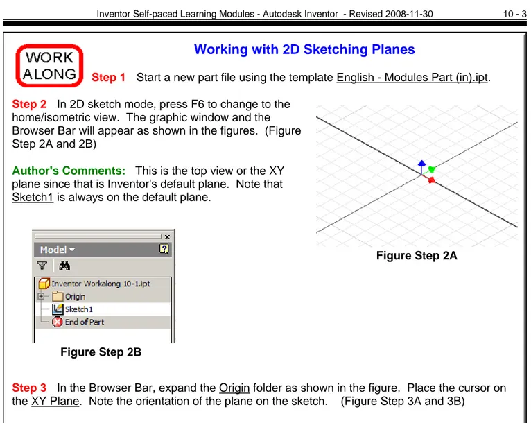
Working with 2D Sketching Planes
Step 1 Start a new part file using the template English - Modules Part (in).ipt.
Step 2 In 2D sketch mode, press F6 to change to the home/isometric view. The graphic window and the Browser Bar will appear as shown in the figures. (Figure Step 2A and 2B)
Author's Comments: This is the top view or the XY plane since that is Inventor's default plane. Note that Sketch1 is always on the default plane.
Step 3 In the Browser Bar, expand the Origin folder as shown in the figure. Place the cursor on the XY Plane. Note the orientation of the plane on the sketch. (Figure Step 3A and 3B)
Author's Comments: The XY Plane is the top view. Figure Step 2B
Inventor Self-paced Learning Modules - Autodesk Inventor - Revised 2008-11-30 10 - 4 Figure Step 4B Figure Step 4A Figure Step 5A Figure Step 5B Figure Step 6 Step 4 Place the cursor on
the XZ Plane in the Browser Bar. Note the orientation of the plane on the sketch. (Figure Step 4A and 4B)
Author's Comments: The XZ Plane is the front view.
Step 5 Place the cursor on the YZ Plane in the Browser Bar. Note the orientation of the plane on the sketch. (Figure Step 5A and 5B)
Author's Comments: The YZ plane is the right side view.
Step 6 Place the cursor anywhere in the graphic window and right click the mouse. In the right-click menu, click Finish Sketch. Save the part with the name Inventor Workalong 10-1. (Figure Step 6)
Inventor Self-paced Learning Modules - Autodesk Inventor - Revised 2008-11-30 10 - 5
Dimensioned Multiview Drawing
Home or Isometric View
Author's Comments: The object shown below is the model that you will be constructing in this workalong.
Author's Comments: Before starting the base sketch you must pick the best view to draw it on. It should, in most cases, be the view with the most complex contour. For this object, the best view to use is the front view or the XZ plane.
Step 7 While In model mode, expand the Origin folder in the Browser Bar and right-click the XZ plane. In the right-click menu, click New Sketch as shown in figure. (Figure Step 7)
Inventor Self-paced Learning Modules - Autodesk Inventor - Revised 2008-11-30 10 - 6
Figure Step 8A
Figure Step 8B
Step 8 The graphic window will change to sketch mode in the XZ plane. Note that in the Browser Bar a new sketch will appear named Sketch2. (Figure Step 8A and 8B)
Author's Comments: Since Sketch1 was not used, it is blank and is an unconsumed sketch.
Step 9 Project the Center Point onto the sketch plane. Draw the base sketch for the object applying all of the
necessary geometrical constraints to maintain the shape of the sketch. Note the location of X0Y0Z0. Insert the necessary driving dimensions to fully constrain the sketch. (Figure Step 9A and 9B)
Author's Comments: All the lines in the sketch should display purple If they do not, start the workalong over again.
Inventor Self-paced Learning Modules - Autodesk Inventor - Revised 2008-11-30 10 - 7
Figure Step 10
Figure Step 11
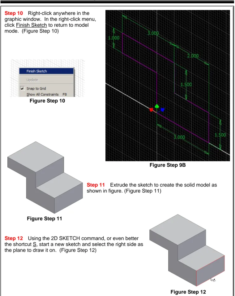
Figure Step 12 Step 10 Right-click anywhere in the
graphic window. In the right-click menu, click Finish Sketch to return to model mode. (Figure Step 10)
Step 11 Extrude the sketch to create the solid model as shown in figure. (Figure Step 11)
Step 12 Using the 2D SKETCH command, or even better the shortcut S, start a new sketch and select the right side as the plane to draw it on. (Figure Step 12)
Inventor Self-paced Learning Modules - Autodesk Inventor - Revised 2008-11-30 10 - 8
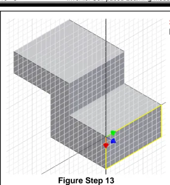
Step 13 The grid will display on the right side. It will be Sketch3 in the Browser Bar. (Figure Step 13)
St ep 14 Draw three lines for the slot. Apply all of the necessary geometrical and dimensional constraints to fully constrain the sketch. (Figure Step 14A and 14B)
Author's Comments: Ensure that you snap onto the edge when you start the first line and end the third line. By doing that, you only are required to draw 3 lines to fully constrain the sketch. See Module 7 if you have trouble doing this.
Author's Comments: All three lines in the sketch should display purple to indicate the sketch is fully constrained. Do not continue on with this
workalong until the sketch is fully constrained. Figure Step 13
Figure Step 14A
Inventor Self-paced Learning Modules - Autodesk Inventor - Revised 2008-11-30 10 - 9
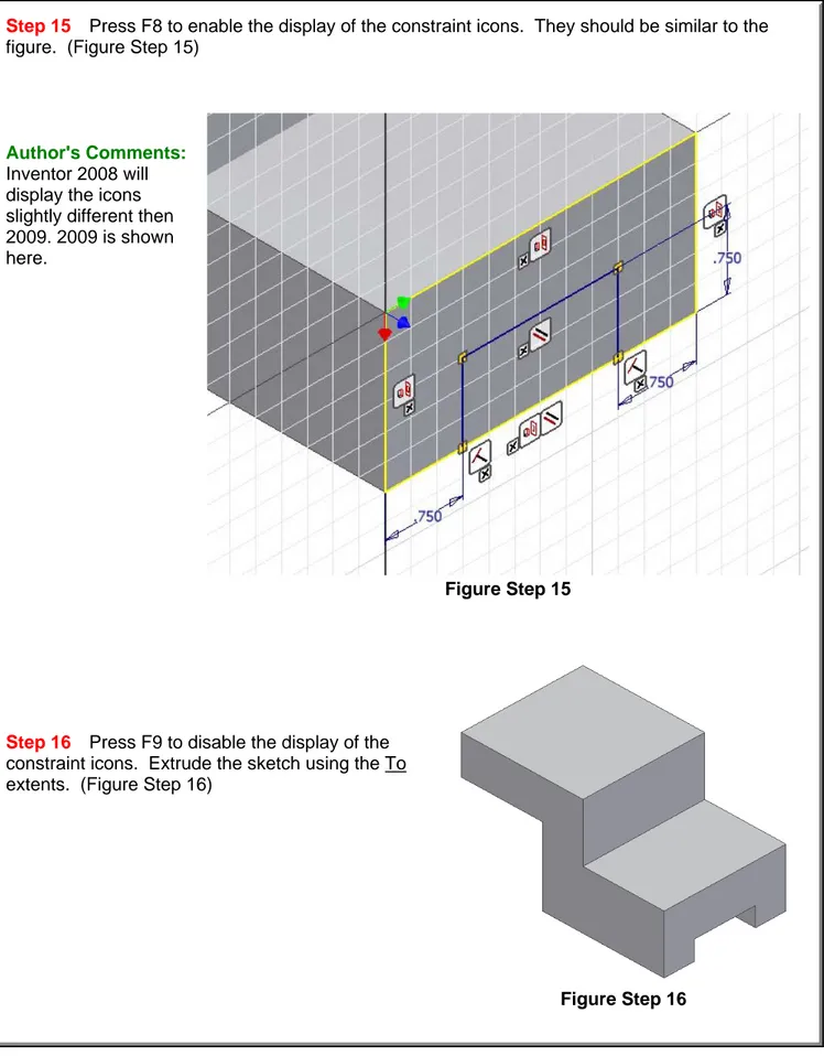
Figure Step 16
Step 15 Press F8 to enable the display of the constraint icons. They should be similar to the figure. (Figure Step 15)
Author's Comments: Inventor 2008 will display the icons slightly different then 2009. 2009 is shown here.
Step 16 Press F9 to disable the display of the constraint icons. Extrude the sketch using the To extents. (Figure Step 16)
Inventor Self-paced Learning Modules - Autodesk Inventor - Revised 2008-11-30 10 - 10
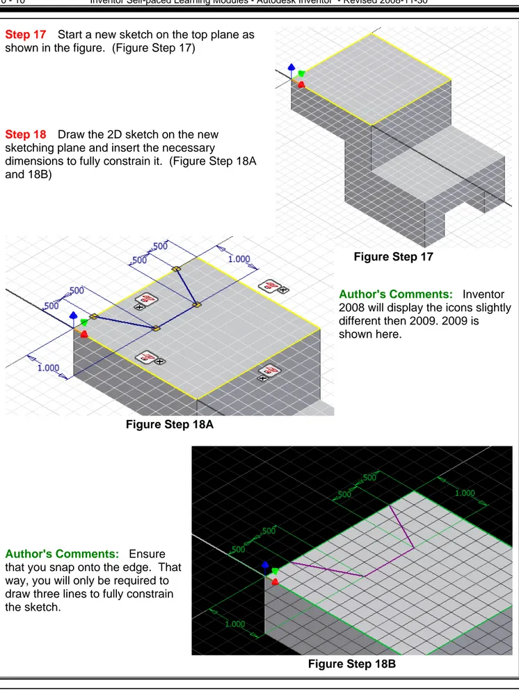
Step 17 Start a new sketch on the top plane as shown in the figure. (Figure Step 17)
Step 18 Draw the 2D sketch on the new sketching plane and insert the necessary
dimensions to fully constrain it. (Figure Step 18A and 18B)
Author's Comments: Inventor 2008 will display the icons slightly different then 2009. 2009 is shown here.
Author's Comments: Ensure that you snap onto the edge. That way, you will only be required to draw three lines to fully constrain the sketch.
Figure Step 17
Figure Step 18A
Inventor Self-paced Learning Modules - Autodesk Inventor - Revised 2008-11-30 10 - 11
Figure step 19
Figure Step 20
Step
19 Extrude the top sketch to complete the solid model. (Figure Step 19)Step 20 Change the view to the home or isometric view and apply the color Black Chrome. Orbit or rotate the view to check the bottom of the solid model. (Figure Step 20)
Step 21 Save and close the file.
The Key Principles in Module 10
1. Inventor has three predefined planes that can be used to draw the base sketch on. They are the XY, XZ and YZ planes. The XY plane is the top view, the XZ plane is the front view and the YZ is the right side view.
2. A consumed sketch is a 2D sketch that has been extruded or revolved. An unconsumed sketch is a 2D sketch that is blank or one that has not been extruded or revolved.
Inventor Self-paced Learning Modules - Autodesk Inventor - Revised 2008-11-30 10 - 12
Lab Exercise 10-1 Time Allowed: 45 Min.
Part Name: Inventor Lab 10-1 Template: English - Modules Part (in).ipt Units: Inches Project: Inventor Course Color: Metal-Titanium (Polished) Material: N/A
3D Model - Home or Isometric View
Dimensioned Multiview Drawing Completed Solid Model -
Home or Isometric View
Suggested Base View -Front XZ Plane Instructions:
1. Project the center point onto the base sketching plane. 2. Note the location of X0Y0Z0.
3. Draw the necessary sketches and extrude them to produced the solid model shown below. Apply all of the necessary geometrical and dimensional constraints to fully constrain all sketches. 4. Apply the color as shown above.
Inventor Self-paced Learning Modules - Autodesk Inventor - Revised 2008-11-30 10 - 13
Lab Exercise 10-2 Time Allowed: 45 Min.
Part Name: Inventor Lab 10-2 Template: Metric - Modules Part (mm).ipt Units: Inches Project: Inventor Course Color: Zinc Chromate Material: N/A
3D Model - Home or Isometric View
Completed Solid Model -Home or Isometric View Instructions:
1. Project the Center Point onto the base sketching plane. 2. Note the location of X0Y0Z0.
3. Draw the necessary sketches and extrude them to produced the solid model shown below. Apply all of the necessary geometrical and dimensional constraints to fully constrain all sketches. 4. Apply the color shown above.
5. Save the file with the name Inventor Lab 10-2 as shown above.
Dimensioned Multiview Drawing Suggested Base View -
CHAPTER 2
Tutorial
Applying Colors to Parts
Learning Objectives
After Completing this chapter, you will be able to:
• Apply colors to entire parts, features and surfaces
• Override part colors with feature and face colors
Required Objectives
Before stating this tutorial you should have been able to:
•
Select features in the object browser
Understand the concept of colors
Figure 1
1. Open the file Screwdriver1.ipt. Note that the screwdriver’s default color is gray (As Material).
2. Find Loft1 in the browser and right click on it. Select Properties from the context menu as shown in Figure 2.
3. In the Feature Properties dialogue, select BlackRubber in the Feature Color Style pulldown and click OK. The body of the screwdriver will change to black . 4. Select Emboss1 in the browser and right click on it. Select Properties from the
5. In the Feature Properties dialogue, select Red in the pulldown and click OK. Only the first ridge on the body of the screwdriver will change to red. The rest will remain gray as shown in Figure 3.
Figure 2
Figure 3
6. Select CircularPattern1 in the browser and right click on it. Select Properties from the context menu.
7. In the Feature Properties dialogue, select Red in the pulldown and click OK. The remaining ridges on the body of the screwdriver will change to red.
8. Zoom in on the base of the screwdriver and select the four fillets and face that make up the base. After all five faces have been selected, as shown in Figure 4, right click and select Properties from the context menu to open the Face Properties
dialogue. In the Face Color Style, select Yellow and click OK.
Select multiple faces by holding down the Control key. To remove a face or line, hold Shift and select the line.
9. Repeat the same process for the chamfers that make up the part of the screwdriver that connects to the blade as shown in Figure 5.
Figure 4
Figure 5
10. Change the default color of the part via the color pulldown on the standard toolbar to any other color. Notice that only the color of the shaft and blade change. This is because the blade extrusion and loft’s properties were not overridden and their color styles were set to “as part”.
© By downloading this document you agree to the following:
Educators only may use this material for educational purposes only at an
accredited high school or college. As an educator, you may copy this
document as many times as you need for your classroom students. You may
not distribute, publish, modify, display, email/transmit to others, create other
similar works from this document, in any way. Any other use of this
document is strictly prohibited.
Disclaimer:
This tutorial is designed for educational purposes only. It is not to be used for
manufacture of parts, drawings or assemblies or merchandising of products. The author
or publisher shall not be liable for any damages, in whole or part, from the use of this
tutorial and its materials or any revisions of this tutorial or materials.
CHAPTER 2
Tutorial
Defining Materials
Learning Objectives
After Completing this chapter, you will be able to:
• Define materials and their associated colors
Required Objectives
Before starting this tutorial you should have been able to:
•
Apply colors to parts
Create new colors
Figure 1: Idler Bracket 1. Open the file IdlerBracket1.ipt.
2. Select Format>Materials and click New. Name the new material Aluminum-6061.
3. Enter the properties of the material as shown in Figure 2. While Inventor only utilizes values for density and render color, it is good practice to enter all values at creation time for use in 3rd party applications.
Professional Tip
All values for physical properties have metric units. Be sure to convert your values if your source is stated in English units.
4. Assign the Rendering Style of Metal-AL-6061 (Flat) to the new material. Note: This color was predefined in the part file. If you want to apply a custom color, you must create it before creating the material.
5. Click Save.
Figure 2: Physical Properties of Aluminum 6061
6. Click New once again and create a new material Steel, Stainless 302, enter the properties of the material as shown in Figure 3.
7. Assign the Rendering Style of Metal-Steel to the material.
Figure 3: Physical Properties of Stainless Steel 302 8. Click Save, then Close and return to the model.
9. In the model environment, select File>iProperties from the main menu. Click on the Physical tab.
10. Select Aluminum-6061 from the Material pulldown. Note the mass of the part. Click Apply, note how the color of the part has changed.
11. Change the material to Steel, Stainless 302 and note the mass of the part. Click OK and return to the model. Again, note that the color of the model has changed.
Figure 4
`
© By downloading this document you agree to the following:
Educators only may use this material for educational purposes only at an
accredited high school or college. As an educator, you may copy this
document as many times as you need for your classroom students. You may
not distribute, publish, modify, display, email/transmit to others, create other
similar works from this document, in any way. Any other use of this
document is strictly prohibited.
Disclaimer:
This tutorial is designed for educational purposes only. It is not to be used for
manufacture of parts, drawings or assemblies or merchandising of products. The author
or publisher shall not be liable for any damages, in whole or part, from the use of this
tutorial and its materials or any revisions of this tutorial or materials.
CHAPTER 3
TUTORIAL
Simple Extruding of a Sketch
Learning Objectives
After completing this tutorial, you will be able to:
•
Sketch an object
•
Extrude a sketch
Required Competencies
Before starting this tutorial, you should have been able to:
• Construct, constraint and dimension sketches
• Make work planes visible
Figure 1 1. Open a new Standard.ipt
2. Click on the plus sign next to origin in the Model panel bar as shown in Figure 2. Click the right mouse button over the XY Plane and select visibility as shown in Figure 3.
Figure 2 Figure 3
3. Select the Line Button in the 2D sketch panel and create the sketch shown in Figure 4.
4. Once the sketch is completed and fully dimensioned click on Return in the Inventor Standard menu at the top of the screen.
Figure 5
5.
Move the cursor into the workspace and right click to open the options menu. Select Isometric View as shown in Figure 6.Figure 6
6. Select Extrude in the Part Features menu as shown in Figure 7. This opens the Extrude dialog box as shown in Figure 8.
Figure 7 Figure 8
7. The Profile button should be selected as shown in Figure 9.
Figure 9
8. Move the cursor over the sketch till it becomes highlighted and left click, making sure that the circle is not included, as shown in Figure 10.
Figure 10
9. Set the distance as .5 in and select the middle button with the arrow pointing up and away from the yellow plane as shown in Figure 11.
Figure 11
10. Click on the OK button and the finished part should look like Figure 12.
Figure 12
© By downloading this document you agree to the following:
Educators only may use this material for educational purposes only at an
accredited high school or college. As an educator, you may copy this
document as many times as you need for your classroom students. You may
not distribute, publish, modify, display, email/transmit to others, create other
similar works from this document, in any way. Any other use of this
document is strictly prohibited.
Disclaimer:
This tutorial is designed for educational purposes only. It is not to be used for
manufacture of parts, drawings or assemblies or merchandising of products. The author
or publisher shall not be liable for any damages, in whole or part, from the use of this
tutorial and its materials or any revisions of this tutorial or materials.
CHAPTER 3
TUTORIAL
Simple Extruding of a Sketch
Learning Objectives
After completing this tutorial, you will be able to:
•
Sketch an object
•
Extrude a sketch
Required Competencies
Before starting this tutorial, you should have been able to:
• Construct, constraint and dimension sketches
• Make work planes visible
Figure 1 1. Open a new Standard.ipt
2. Click on the plus sign next to origin in the Model panel bar as shown in Figure 2. Click the right mouse button over the XY Plane and select visibility as shown in Figure 3.
Figure 2 Figure 3
3. Select the Line Button in the 2D sketch panel and create the sketch shown in Figure 4.
Figure 4
4. Once the sketch is completed and fully dimensioned click on Return in the Inventor Standard menu at the top of the screen.
5. Select Extrude in the Part Features menu as shown in Figure 6. This opens the Extrude dialog box as shown in Figure 7.
Figure 6 Figure 7
6. The profile should already be highlighted in your work space. In the area highlighted under the Extents category type in a depth of 2 in as shown in Figure 8.
Figure 8
7. Select the button that has arrows pointing in both directions from the yellow plane at the bottom of the dialog box; this is considered a midplane extrusion. Click the OK button.
8. Move the cursor into the workspace and right click to open the options menu. Select Isometric View as shown in Figure 9.
Figure 9
9. The finished part should look as shown in Figure 10.
Figure 10
© By downloading this document you agree to the following:
Educators only may use this material for educational purposes only at an
accredited high school or college. As an educator, you may copy this
document as many times as you need for your classroom students. You may
not distribute, publish, modify, display, email/transmit to others, create other
similar works from this document, in any way. Any other use of this
document is strictly prohibited.
Disclaimer:
This tutorial is designed for educational purposes only. It is not to be used for
manufacture of parts, drawings or assemblies or merchandising of products. The author
or publisher shall not be liable for any damages, in whole or part, from the use of this
tutorial and its materials or any revisions of this tutorial or materials.
CHAPTER 6
Placed Features
Learning Objectives
After Completing this chapter, you will be able to:
• Understand and create the following features:
•
Holes
• Fillets
• Chamfers
• Shell
•
Patterns (Rectangular, Circular)
Placed features are predefined features that require specific values as well as the desired positioning. In order to use placed features there must be a sketched base feature already created. Editing of placed features is done in the Browser like sketched features. The use of these placed features is usually more efficient than the use of sketched features. Please refer to “Learning Inventor” Chapter 6.
HOLES
Creating Holes
There are three types of holes to choose from in Inventor: drilled, counterbore, and
countersink. Each of these hole types also have the option of being tapped. Holes can
have the diameter and depth or termination determined in the Hole menu box.
Steps to creating holes
1. Have a base feature created in which the hole will be placed on. 2. Choose the sketch plane (surface) that the hole will be placed.
3. In order to use the hole command you must place a Point, Hole Center from the Sketch Panel Bar, Figure 1 .
Figure 1 Figure 2
4. Once the point has been placed in the desired position return to the Features Panel Bar and select the Hole command shown in Figure 2.
5. The Hole dialog box will then open providing the different options for hole creation. There are four tabs with various setting options available for each.
Type Tab
This tab allows you to select the hole type, termination, centers, and hole diameter as shown in Figure 3.
• Hole Types include: drilled, counterbore, and countersink. • There are three types of Termination to choose from:
Distance: allows you to give a specific depth for the hole. Through All: the hole will cut through the entire part. To: allows you to choose a plane in which the hole will stop.
• Centers: this button will allow you to choose multiple hole centers that will share the same hole type.
• Hole Diameter: allows you to change the diameter of the hole by selecting the dimension in the dialog box and typing in the desired dimension. See Figure 3.
Figure 3 Threads Tab
This tab allows you to choose whether you want the hole to be tapped and set the various values that can be defined. Values that can be changed are the thread depth, thread type, and thread direction (Right Hand, Left Hand). See Figure 4.
Size Tab
This tab allows you to set the thread’s nominal size, pitch, class, and diameter.
Options Tab
Figure 4 NOTE
Any attribute of a hole can be edited by accessing the edit feature command in the Model Panel.
Example 1
Open the file “Lever.ipt”
Figure 5
Select Sketch from the Command Bar
Click on the top surface of Extrusion 1
Choose Point, Hole Center and click on the center points of
the two arcs of Extrusion 1 as shown in Figure 7.
Figure 7
o Once you have placed the hole centers click Return.
Select Hole from the Features Panel Bar
A Dialog box will appear with the hole options. Edit the Hole termination and diameter as shown in Figure 8.
Figure 8
Next choose the Threads tab
Select Tapped and Full Depth
Click the OK button
Figure 9
Select the sloped circular surface as the new sketch plane.
Figure 10
Place the Point, Hole Center at the center point of the circle.
Figure 11
Click Return
Select the Hole command.
Figure 12
Choose Counterbore for the hole type and set the dimensions as shown in Figure 13.
Figure 13
Click the OK button
Figure 14
Select the sloped rectangular surface as your new sketch plane.
Figure 15
Figure 16
Locate the Point by dimensioning it .75 in from the right edge, and .625 from the top edge. Refer to Chapter 5
Figure 17
Click Return
Select the Hole feature.
Choose Countersink for the hole type and set the dimensions as shown.
Figure 18
Click the OK button.
The finished part with all the placed holes.
FILLETS & CHAMFERS
Creating Fillets
Inventor has three different styles of Fillets that can be placed from the feature menu on a given part. The first style, constant, creates fillets with the same radius from start to finish of the edge selected. Constant fillets have the following three selection options: Edge, Loop, Feature.
Edge
This allows you to select individual edges of an object that need to be filleted. If there are tangent edges they will be selected as one.
Loop
Loop selects all edges of a surface that creates a closed loop. Feature
The feature option will place fillets on all edges of a selected object.
Steps to creating a constant fillet
1. Have a base feature created in which the fillets will be placed on. 2. Choose the selection option and set the desired radius.
3.
Select the edges on the object that will be filleted using whichever selection option desired.4. Once all edges that will have the fillet placed on them are selected click the OK button and the fillets will be placed.
Example 2
Open the file “holder.ipt”
Select Fillet from the Features Bar which will bring up the Fillet Dialog
box.
Figure 21
Set the fillet radius to 6mm and select the four corners as shown in Figure 21 and click OK or press Enter on the keyboard.
Figure 22 Figure 23
Once again select Fillet.
Set the fillet radius to 3 and choose loop for the select mode.
Choose all the inner surfaces of the part.
Figure 25 Figure 26 Figure 27
Figure 28 Figure 29
Once all areas are selected click OK or press Enter on the keyboard. The finished part should look like Figure 29.
Example 3
Open the file “variable fillet.ipt”
Figure 31
Select Fillet from the Features Bar and click on the Variable tab
Figure 32
Click on the top front edge of the part. Notice that the whole edge which includes
the curves is selected.
Figure 33
can be varied. Notice that there are 5 work points along the selected edge. Refer to Chapter 7 Work Features. Select each point in order from 1 – 5 as shown in Figure 34.
Figure 34
In the dialog box click on each point and set the radius to the required value as
shown in the following figures.
Once all radii are set click OK or press Enter on the keyboard.
The finished part should look like Figure 36.
Figure 36
Creating Chamfers
Chamfers are created much in the same way as fillets. When creating chamfers the edge between two surfaces is selected and the chamfer will be placed. The three different styles of chamfers to choose from are Distance, Distance and Angle, and Two Distances.
Distance
This allows you to set the distance offset from the edge selected and places a 45° chamfer on the edge.
Distance and Angle
Distance and angle allows you to change the angle of the chamfer as well as setting the distance of offset. Once the two attributes are set, the edge to be chamfered must be selected as well as the surface in which the distance will be measured.
Two Distances
This option allows the offset distances of each surface to be set. Once the edge to be chamfered is selected, Distance 1, which will be offset on the surface highlighted, must be set followed by Distance 2.
Example 4
Open the file “Cover box.ipt”
Figure 37
Select Chamfer from the Features Bar.
Choose distance and set the value for the distance to .75in.
Figure 38
Click on the 2 vertical edges of the front left surface to place the chamfer.
Figure 39
Figure 40
Select Chamfer from the Features Bar again.
Choose Distance and Angle and set the value for the distance to .25in and the angle to 60°.
Figure 41
The select Face tab should already be selected, select the top suface of the part and
left click.
Figure 42
This surface will be the direction of offset from each edge chosen that the distance
will be measured.
Figure 43
Click OK or press Enter on the keyboard.
Figure 44
SHELL
Creating Shells
Shells are useful tools for creating parts that have thin walls in Inventor. The shell feature has the ability to have a part be hollow or to remove a portion of a face. Some parts may require different wall thicknesses in different sections of the part which can be accomodated with the shell command.
Steps to creating basic shells
1. Have a base feature created that will have a portion hollowed out or shelled.
2. Select Shell from the Features Panel Bar.
Figure 45
3. Set the wall thickness as desired and choose the faces that will be removed if necessary.
4. Once all surfaces are selected click OK or press enter and the part will be shelled.
Example 5
Open the file “Cover box.ipt”
Figure 46
Select Shell from the Part Features panel
Make sure that the Remove Faces button in the dialog box is depressed as shown in
Figure 47
Move the cursor over the top surface of the part and click to select. This will highlight that face in which material will be removed.
Figure 48 Figure 49
Set the thickness of the walls to .25in as shown in Figure 49.
Click OK or press Enter on the keyboard and the part will appear with walls rather
than a solid, with the top face being open as shown in Figure 50.
PATTERNS
Creating Patterns
The Pattern feature is useful when you have a feature of the part that has multiple instances. By using the pattern command, the selected feature will be copied and placed given the dimensions specified. There are two types of patterns to choose from in Inventor: circular and rectangular. Circular patterns will place the features in a pattern around a given axis, while rectangular patterns will place them in rows and or columns.
Steps to creating patterns
1. Have a base feature created in which the pattern will be placed on. 2. Choose the feature that will be patterned.
3. Set the direction/axis that the pattern will follow.
4. Set the count and spacing/angle the pattern will follow.
Example 6
Open the file “circular pattern.ipt”
Figure 51
Select Circular Pattern from the Part Features panel, this will open the pattern
dialog box.
Figure 53
The Features selection button should be depressed, if not click on it. Now click on the hole that is at the top of extrusion 1 or click on extrusion 2 in the Browser.
Figure 54 Figure 55
Click on the rotation axis selection button to choose the axis that the pattern will be
revolved around.
Figure 56
We will use the given axis of extrusion 1. Select and click on the base feature as shown in Figure 57.
Figure 57 Figure 58
Set the Count to 6 instances and the Angle to 360°.
Figure 59
Click OK or press Enter on the keyboard.
NOTE
Try changing the Instances and Angle values by editing the feature in the Browser and see what happens to the part.
Example 7
Open the file “rectangular pattern.ipt”
Figure 61
Select Rectangular Pattern from the Features Bar, this will open the pattern dialog
box.
Click on the cylinder that is at the bottom left of extrusion 1 or click on extrusion 2 in the Browser.
Figure 64 Figure 65
Now that the feature to be patterned is selected, click on the Direction 1 selection
button and choose the bottom edge of the base feature.
Figure 66 Figure 67
Notice the direction that the patern is going to be copied. To chage the direction
click on the Path button to switch the direction of pattern to the right as shown in Figure 69.
Figure 68 Figure 69
Set the Count to 5 and the Spacing to 1.0in.
Figure 70
Click on the Direction 2 selection button and choose the left vertical edge of the base
feature.
Set the Count to 3 and the Spacing to 1.0in. Click OK or press Enter on the keyboard.
Figure 73
The finished part with both patterns added should look like Figure 74.
Figure 74
© By downloading this document you agree to the following:
Educators only may use this material for educational purposes only at an
accredited high school or college. As an educator, you may copy this
document as many times as you need for your classroom students. You may
not distribute, publish, modify, display, email/transmit to others, create other
similar works from this document, in any way. Any other use of this
document is strictly prohibited.
Disclaimer:
This tutorial is designed for educational purposes only. It is not to be used for
manufacture of parts, drawings or assemblies or merchandising of products. The author
or publisher shall not be liable for any damages, in whole or part, from the use of this
tutorial and its materials or any revisions of this tutorial or materials.
CHAPTER 7
TUTORIAL
Advanced Part Features
Learning Objectives
After Completing this chapter, you will be able to:
• Create the following features:
• Sweeps
•
Lofts
•
Coils
• Threads
• Ribs & Webs
•
Face Draft
• Split Feature
• Slice Graphics
Advanced part features will allow the creation of more complex objects or parts that could not be created by basic boolean operations. The use of these techniques will assist in creating complex transitions and shapes.
SWEEPS
Creating Sweeps
Using the sweep feature is a more efficient way of creating piping, tubing and other complex shapes that follow a path.
Steps to creating sweeps
1. Create a sketch of the path that the sketched feature will follow. 2. Create a sketched feature that is a cross section.
3. Use the sweep command to create the part.
NOTE Make sure that the path forms a continuous line.
TUTORIAL 1
Open a new Standard. ipt
Make the XZ and YZ planes visible.
Create the sketch of the paperclip. (Figure 1)
Figure 1
Once you have created the sketch click Return Change your view to Isometric
Figure 2
Click on Project Geometry and select the left verticle line. (Figure 3a)
Draw a diameter .125 circle at the projected point. (Figure 3b)
Figure 3a Figure 3b
Once you have finished the sketch click Return
Click on the Sweep button in the Part Features menu bar
The profile should already be highlighted and the path button selected
Figure 5
Click on the line that was created in Sketch1. (Figure 6)
Figure 6
Figure 7
COIL
Creating Coils
Coils are a useful option for creating such things as springs, coils, and other helical shapes. They can be used to create solids or with the cut option to create cuts in a part. There are three different tabs available in the coil dialog box.
Coil Shape
This tab allows you to choose the profile to be coiled as well as the direction and axis the coil will follow.
Coil Size
In the coil size tab there are options for adjusting the type of parameters for creating the coil. Depending on what parameters are chosen for creation of the coil, there are places for setting the pitch, height, revolution, and taper.
Coil Ends
This tab allows the designer to determine the conditions of the start and end of the coil feature allow for a natural coil or one with flat ends.
Steps to creating a coil
1. Create an unconsumed sketch, or profile, that is a cross section of the coil feature that will be created.
2. Have an axis in which the coil will be rotated around. 3. Use the coil option to create the part.
TUTORIAL 2
Open a Standard(mm).ipt Make the base planes visible.
Create a 5mm circle below the XZ Plane.
Figure 8
Use Project Geometry, and project the XZ plane to be used as the axis.
Dimension the center of the circle to projected XZ plane. Give it a dimension of 15.
Figure 9
Click Return.
Figure 10
The Coil dialog box will open and the circle should already be selected as the profile.
Notice that the Axis button is selected.
Figure 11
Click on the XZ plane as the axis of revolution.
Figure 12
Select the Coil Size tab in the dialog box and change the settings as shown in Figure 13.
Figure 13
Next select the Coil Ends tab and set the Start to Flat.
Figure 14
Click OK and the result should look like Figure 15.
THREADS
Creating Threads
The thread feature in Inventor can be used to create a graphical representation of both internal and external threads. It does not actually remove or add material, it simply places a graphical representation to give the appearance of threads as well as allows for thread notes in the drawing mode.
Steps to creating threads
1. Have a base cylindrical feature with the major diameter dimension created that will have the threads placed on it.
2. Select Threads from the Features Panel Bar.
3. Select the surface/edge threads will be placed and set the data necessary for creation.
TUTORIAL 3
Open part “Thread.ipt”
Click on Thread in the Feature menu.
Figure 16
This will open Thread Feature dialog box.
Click on the cylinder surface at the front right edge of the bolt. Make sure that Full Length is not checked in the dialog box.
Figure 18
Set the Length to 2.5 inches.
Figure 19
Click on the Specifications tab to set the thread type.
Set the Pitch to 1/2-13 UNC. Click OK and the threads should appear as Figure 21.
Figure 21
RIBS & WEBS
Creating Ribs & Webs
Ribs and webs use an unconsumed sketch to create features that are used as reinforcement in molded parts. By using a single line and the rib feature, Inventor will create a closed ribbed feature or an open webbed feature set to the specifications determined in the Rib Dialog box.
Steps to creating ribs
1. Have a base feature created in which the rib will be placed on. 2. Sketch the profile of the rib or web.
3. Select the Rib feature button in the Feature menu bar.
Click on the profile.
4.
Set the attributes in the dialog box as desired and click OK.
TUTORIAL 4
Open the file “base.ipt”
Figure 22
Sketch a line from the mid point of the top left projected edge to the mid point of the
bottom right projected edge.
Figure 23 Figure 24
Create another line from the mid point of the bottom left projected edge to the mid point of the top right projected edge.
Figure 25 Figure 26
Click Return.
Click on the Rib button in the Part Feature menu bar.
Figure 28
In the Rib dialog box the profile button should already be selected, if not then select
the profile button.
Figure 29
Click on the two lines just created as the profile.
Set the thickness to .25in. Then click on the Direction button.
Figure 31
Set the direction to be facing towards the interior of the part.
Figure 32
Click on OK. Nottice that the rib did not go through the hole portion of the part.
Next right click on rib1 in the browser and edit feature.
Change the Extents to finite.
Figure 34
A new attribute box opens inside the Extents section of the dialog box. Change this
dimension to .25 inches.
Figure 35
Click OK. Nottice the change from rib to web.
FACE DRAFT
Creating Face Drafts
Face draft adds an angled/sloped surface to any face of a part either internal or external. This is commonly used for molded or cast parts.
Steps to creating a face draft
1. Have a base part created in which a face/surface will be sloped. 2. Choose the face draft command in the part feature menu.
3. Select the pull direction that the mold will be removed from the part.
4. Select the face/faces that will have the draft applied to and set the angle of draft.
TUTORIAL 5
Open the file “draft.ipt”
Figure 37 Figure 38
Select Face Draft from the Features Bar.
Select the interior bottom surface.
Figure 39 Figure 40
Next select the interior faces that will be drafted, since there are fillets on the corners it will automatically choose all the faces. Select the top left edge where the interior vertical faces meet the top face.
Set the Draft Angle to 5° and press Enter or click OK.
Figure 42
Change the part display to Hidden Edge Display. Notice the slope that has been
applied to the faces.
Figure 43
SPLIT
FEATURE
Creating Split Features
Cutting and removing faces and parts can be performed using the split feature tool. By using a sketched shape, surface, or workplane to use as a cutting edge, the entire part can be split and have a portion removed.
Steps to creating split feature 1. Have a base part created.
2. Either select a created sketch geometry, a workplane, or use an existing surface to be used as the cutting edge.
3. Select whether the part or the face will be split.
4. If the part is to be split select the direction that the material will be removed from.
TUTORIAL 6
Open a new “Standard.ipt” Create the following sketch.
Figure 45
Extrude the profile 2 inches..
View the part in isometric and select the top surface as the new sketch plane. (Figure
Figure 46
Sketch a three point arc from corner to corner, giving the arc a dimension of 6.5 inches.
Figure 47
Select Split from the Part Features menu bar.
Figure 48
In the Split dialog box click on Split Part.
Select the Split Tool button and click on the arc.
Figure 50
If the arrow is not pointing toward you, click on the reverse direction button that is
in the Remove section of the dialog box.
Figure 51
Click OK or press Enter.
SLICE GRAPHICS
Using Slice Graphics
Some parts are rather complex and require sketching on planes or surfaces that are dificult to see. For these problems the use of Slice Graphics can be handy. This will temporarily remove part material so that you can view the sketch plane to work easier.
Steps for slicing graphics
1. Have a base part created in which the sketch plane goes through. 2. Using the View pull down menu or by right clicking the mouse in the work area select Slice Graphics.
TUTORIAL 7
Open the file “swing arm.ipt”
Create a work axis through the counterbores in the front and the back of the part.
Figure 53 Figure 54
Create a new workplane bisecting the part through the new workaxises.
Choose the new workplane as the sketch.
Figure 56
Click the right mouse button in the work area and select Slice Graphics.
Figure 57
Notice that we can now view inside the object along the sketch plane we are using as
Figure 58
We can now project geometry onto our current sketch plane and work without using
wireframe.
© By downloading this document you agree to the following:
Educators only may use this material for educational purposes only at an
accredited high school or college. As an educator, you may copy this
document as many times as you need for your classroom students. You may
not distribute, publish, modify, display, email/transmit to others, create other
similar works from this document, in any way. Any other use of this
document is strictly prohibited.
Disclaimer:
This tutorial is designed for educational purposes only. It is not to be used for
manufacture of parts, drawings or assemblies or merchandising of products. The author
or publisher shall not be liable for any damages, in whole or part, from the use of this
tutorial and its materials or any revisions of this tutorial or materials.
CHAPTER 7
TUTORIAL
Sweep and Multiple
Thickness Shell
Learning Objectives
After completing this tutorial, you will be able to:
• Create a multiple thickness shell
• Create a sweep
Required Competencies
Before starting this tutorial, you should have been able to:
• Construct, constraint and dimension sketches
• Use free rotate
• Create work planes
• Create holes
2. Select Shell from the Part Features panel bar as shown in Figure 1. This will open the shell dialog box from which the specifications will be set as shown in Figure 2.
Figure 1 Figure 2
3. Rotate the part to view the bottom surface. This will be the face that will be removed. The button next to Remove Faces should be selected already, if not click on the button to select it. Move the cursor to the bottom face and click as shown in Figure 3.
Figure 3
5. Set the wall Thickness to .25 in. as shown in Figure 4. For this part the back walls need to be a thickness of .375 due to structural requirements from the addition of a handle to be placed on the back.
6. Click on the button with the two greater than symbols located at the bottom right corner of the dialog box to open the unique face thickness options dialog as shown in Figure 5.
Figure 5
7. Move the cursor in the white area of the dialog box and click where the words Click to add are located as shown in Figure 6.
8. The words 0 Selected should be highlighted in blue at this time. This option allows the selection of the faces that will have a different thickness than the rest of the faces. Click on the two back surfaces to have the different thickness as shown in Figures 7 and 8.
Figure 7 Figure 8
9. After selecting the two faces it will say 2 Selected. Next click on 0.25 under the Thickness tab of the dialog box and type in .375 as the thickness as shown in Figure 9.
Figure 9
10. Click on the OK button and the shelled part should look like Figure 10.
11. Set the part back to the Isometric view to begin placing the holes. Select Sketch and click on the top surface of the part as shown in Figure 11.
Figure 11
12. Place a Point, Hole Center somewhere on the sketch plane and position it in the center of the face using construction lines and Horizontal and Vertical constraints as shown in Figures 12 and 13.
Figure 12 Figure 13
13. Click on the Return button to switch to the Part Features mode.. Select the Hole feature to open the hole dialog box as shown in Figure 14. Set the hole depth and diameter to 0.5 in. as shown in Figure15.
14. After the hole is created on the top of the part select the left surface, as shown in Figure 16, as the sketch plane for creating the second hole. We don’t need to place a Point,Hole Center because the center point of the bottom right arc will be used as the center of the new hole.
Figure 16
15. Click on the Return button to switch to the Part Features mode. Select the Hole feature to open the hole dialog box. Notice that the button next to Centers is selected. Click on the center point of the bottom arc as shown in Figure 17. Set the Termination to Through All and the diameter to 0.5 in. as shown in Figure18.
Figure 17
16. In order to begin the sweep a new work plane must be created. Create an offset work plane parallel to the top surface down at a distance of -1.75 in. as shown in Figure 19.
Figure 19
17. Choose Sketch from the menu bar and select this new work plane to be the new sketch plane. Once the sketch plane is selected choose the Look At command, Figure 20, and click on the work plane to view the part from the top.
Figure 20
18. Select Project Geometry from the 2D Sketch Panel as shown in Figure 21. Select the top and bottom horizontal edges of the part as shown in Figures 22 and 23.
19. Create the sketch, as shown in figure 24, which will be used as the path for the sweep. Make sure that the center points of the arcs are in line with the left edge and equally spaced from the top and bottom edges of the part. Use the Coincident and Equal constraints to perform this task.
Figure 24
20. Click Return to switch to the Part Feature mode. Switch to the Isometric view and select the left surface as the new sketch plane as shown in Figure 25.
21. Use Project Geometry to project the short line of the previous sketch as a point on the new sketch plane as shown in Figure 26.
Figure 26
22. Draw a circle using the projected point as the center point as shown in Figure 27. Dimension the circle with a diameter of 0.25 in. as shown in Figure 28.
Figure 27 Figure 28
22. Click Return to and select Sweep from the Part Features panel to open the Sweep Dialog box as shown in Figures 29 and 30.
23. Select the circle that was just sketched as the Profile as shown in Figure 31. Next click on the button next to Path in the dialog box and click on the first sketch as shown in Figure 32 as the sweep path.
Figure 31 Figure 32
24. Once the Path and Profile of the sweep are selected click OK, which should create the finished part shown in Figure 33.
© By downloading this document you agree to the following:
Educators only may use this material for educational purposes only at an
accredited high school or college. As an educator, you may copy this
document as many times as you need for your classroom students. You may
not distribute, publish, modify, display, email/transmit to others, create other
similar works from this document, in any way. Any other use of this
document is strictly prohibited.
Disclaimer:
This tutorial is designed for educational purposes only. It is not to be used for
manufacture of parts, drawings or assemblies or merchandising of products. The author
or publisher shall not be liable for any damages, in whole or part, from the use of this
tutorial and its materials or any revisions of this tutorial or materials.
CHAPTER
TUTORIAL
Coil Features in Parts
Learning Objectives
After completing this tutorial, you will be able to:
• Construct and use coils
Required Competencies
Before starting this tutorial, you should have been able to:
• Construct, constraint and dimension Sketches
•
Project Geometry on Sketch Planes
• Construct Work Features
Figure 1: Impeller 1. Open file impeller_shaft.ipt
2. Construct a new Work Plane parallel to the default XY plane at an offset distance of 4.25”.
a. Click the work plane tool on the part feature toolbar.
Figure 3 b. Expand the Origin in the Browser and click the default XY plane. Figure 4 c. Drag the new work plane to an offset distance of 4.25”.
3. Project the default Y-Axis on the new work plane.
a. Enter Sketch Mode and select the newly constructed work plane as a sketch plane. b. Click the Project Geometry tool. Figure 6 c. Click the Y-Axis in the Browser.
d. Exit Sketch Mode.
4. Construct a new Work Plane 2 making a 24o angle with the previously constructed
Work Plane 1 and passing through the Projected Y-Axis.
a. Click the work plane tool and select the projected Y‐Axis.
Figure 8
b. Click the previously constructed Work Plane 1 and change the angle to 24o to
create Work Plane 2..
Figure 9.a Figure 9.b
5. Construct a new Work Axis 1 coinciding with the Projected Y‐Axis.
6. Turn the visibility of Work plane 1 and the previously constructed Sketch off. Figure 11 7. Click the Look At button and click Work Plane 2. Figure 12 8. Rotate the image 90o. Figure 13 9. Enter Sketch Mode and select work plane 2 as a sketch plane.
10. Right‐click on the work plane and Slice Graphics.
Figure 14.b
Figure 14.a
11. Use the Project Geometry tool and project Work Axis 1 and the Z‐Axis on the work plane.
Figure 15.c
Figure 15.b 12. Construct the following sketch.
Note: The next three (3) pages outline suggested construction steps.
Suggested Construction Steps a. Figure 17.a b. Figure 17.b
c. Trim
Figure 17.c d.
e. Trim and verify that the Tangency Constraints between adjacent arcs are maintained.
Figure 17.e f. The following should be Driven Dimensions.
13. Exit Sketch Mode and Coil the drawn profile about the Z‐Axis, 1/3 of a revolution to a coil height of 2.923” a. Click the Coil tool on the Feature toolbar. Figure 18 b. Select the drawn profile. Figure 19
c. Select the Z‐Axis and the proper Direction and Rotation for the required coil shape.
Figure 20
d. Click the Coil Size tab and adjust the parameters as shown below.
e. Click the Coil Ends tab and select Natural Start and End and click OK.
Figure 22.a
14. Enter Sketch Mode and select Surface A as the sketch plane. Click the Look At button.
Figure 23
15. Construct the .410” diameter hole as shown below and exit Sketch Mode.
16. Coil and Cut the drawn profile with the same parameters as in step 13.
Figure 25.a
17. Create a Circular Pattern of the two Coils about the Z‐Axis with three (3) occurrences in the pattern.
a. Click the Circular Pattern tool on the Feature toolbar and select the two Coils as Features.
Figure 26
b. Click the Rotation Axis button, select the Z‐Axis in the Browser and adjust the required parameters as shown below.
18. Turn the visibility of the YZ plane on.
Figure 28
19. Enter Sketch Mode and select the YZ plane as a sketch plane. Use the Look At and Slice Graphics functions for easy construction. Rotate the image.