(1) INFN, Sezione di Roma Tre - Rome, Italy
(2) Math and Physics Department, University of Roma Tre - Rome, Italy
received 8 June 2020
Summary. — The MICRO MEsh GAseous Structure, micromegas (MM), are highly innovative micro-pattern gas detectors, designed to achieve high spatial reso-lution (σx∼ 100 μm) and high efficiency (>95%) in highly irradiated environments (φ∼ 15 kHz/cm2). For this reason, these chambers were chosen as precision detec-tors for the upgrade of the ATLAS muon spectrometer (New Small Wheel project, NSW), in view of the expected increase of the luminosity at LHC for Run 3 and HL-LHC (High Lumi LHC) programme. Two identical NSW will be built to replace the innermost stations in the two forward regions of the ATLAS muon spectrometer. Each NSW will consists of two different detector technologies: MM and sTGC (small strip Thin Gap Chamber) to provide information both to the ATLAS trigger and to the track reconstruction. The NSW consists of 8 large sectors (LM) and 8 small sectors (SM). To ensure redundancy, each sector will consist of 2 MM chambers and two sTGCs with 4 layers each, for a total of 16 points per track. Four types of MM chambers called LM 1-2 and SM 1-2 are currently under construction, whose production is distributed among different countries: Italy (SM1), Germany (SM2), France (LM1), Greece and Russia (LM2). All the chambers will be trapezoidal in shape, with areas of 2–3 m2. Each MM chamber, composed of 4 reading layers, will provide information about the precision coordinate in ATLAS (η) and, through the two planes with stereo reading (±1.5 degrees), also about the azimuthal coordinate (φ). In this paper the validation procedures of the chambers will be shown as well as the results obtained on the first MM SM1 modules at the cosmic rays stand of the National Laboratories of Frascati.
1. – Introduction and operating principles of the micromegas detectors
The micromegas detectors [1] consist of a planar electrode, a gas gap of a few millime-tres thickness acting as conversion and drift region, and a thin metallic mesh at typically 100–150 μm distance from the readout electrode, creating the amplification region. Both regions are filled with a gas mixture of Ar:CO2 (93%:7%). A sketch of the micromegas
operating principle is shown in fig. 1 [2, 3].
The HV potentials are chosen such that the electric field in the drift region is a few hundred V/cm, and 40–50 kV/cm in the amplification region. When a charged particle traverses the gas gap, ionizes the atoms and the electrons liberated by this ionization process drift towards the mesh.
The electron avalanche takes place in the thin amplification region, immediately above the readout electrode. The drift of the electrons in the conversion gap is a relatively slow process; depending on the drift gas, the drift distance, and the drift field, it typically takes several tens of nanoseconds (vd= 4–5 cm/μs) [2, 3].
2. – The New Small Wheel (NSW) for the ATLAS upgrade
The requirements for the NSW [2, 4] are:
• momentum resolution of 15% at pT = 1 TeV that is translated into a track reso-lution of ∼100 μm for each detector layer and a knowledge of the readout element positions with a high precision of 30–40 μm;
• ability to provide the second coordinate with a resolution of around 5 mm; • tracking efficiency above 90% for each plane;
• ability to cope with high particle fluxes to reject fake triggers (up to Φ = 15 kHz/cm2).
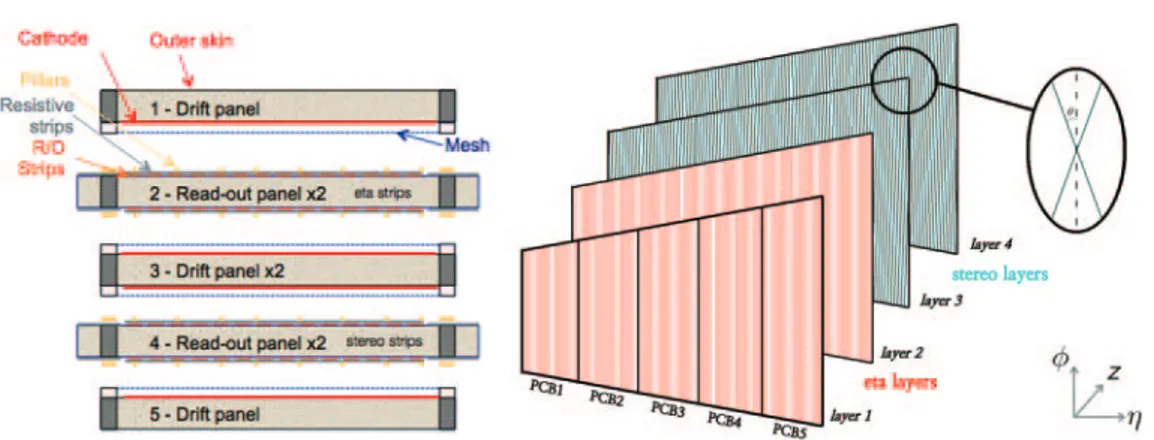
Fig. 3. – Layout of a multiplet of a micromegas detector consisting of three drift panels (two single side outer and one central double side) and two double-side readout panels forming four gas gaps. The first two MM gaps read the precision coordinates (η) and the second two read the second coordinates (φ).
2.1. Micromegas design. – Four different trapezoidal MM modules (SM1, SM2, LM1, LM2) that have to be built are illustrated in fig. 2 [4].
There will be four gas gaps and four readout planes in each module. Two will have the strips running perpendicularly to the radial direction (precision strips or η strips) while the other two will have the strips tilted by a small stereo angle (+1.5◦ and−1.5◦stereo strips, respectively) to allow for the reconstruction of the second coordinate (φ) [4], as shown in fig. 3.
3. – Validation measurements of the MM quadruplet
After the construction and assembly of the micromegas quadruplet, several validation measurements are required to ensure the correct functioning of the chambers:
• the planarity of each face of the chamber;
• inter-alignment of readout planes through optical measurements; • gas tightness;
• high voltage stability;
• efficiency and uniformity of response of the single layer.
3.1. Planarity. – The planarity of the chamber is measured on both external faces and it is carried out using a laser tracker as shown in fig. 4.
Two maps of the heights of the two sides of the chamber are then created and fitted with a plane. The thickness of the chamber is considered as the average difference in height between one face and the other. The planarity of a chamber should be below 80 μm in RMS. The planarities measured for the first modules are at the limit or slightly above the ATLAS limit but are still acceptable.
is on the left of the picture and the sensor is manoeuvred by an operator along all the chamber surface. Right: height map of one side of a micromegas chamber.
3.2. Readout layer alignment . – The optical measurement is a crucial measurement because it checks possible misalignments during the assembling procedure. It is made by reading a precise patterned mask, shown in fig. 5 (left), with CCD cameras as shown in fig. 5 (right). These masks are objects that have a precise position inside the single PCB (there are 6 masks per PCB). Measuring the relative position between the layers it can be traced back to the geometry of all the readout elements.
3.3. Gas tightness. – Another quality test is the gas tightness of the gas gap. The chamber is pressurized inside using a small syringe creating an overpressure of approx-imatively 3 mbar. The pressure decrease is monitored as a function of the time and a linear fit is made to measure the leak of the chamber as shown in fig. 6. If the pressure drop is less than 0.64 mbar/hour the test is considered passed. The gas leaks are well within the requirements.
3.4. HV stability. – High-voltage stability is one of the points on which the micromegas chambers have been most controlled. Each chamber needs a period of so-called “con-ditioning”; at first time the chamber is switched on where the voltage is progressively raised. A standard procedure has been established in order to bring sector to nominal voltage (segmentation in different HV sections of each plane of a SM1 chamber is shown in fig. 7). The first day the ignition starts at 400 V and if the sector remains stable then
Fig. 5. – Left: position of the Rasnik Mask on the first SM1 PCB. Right: picture during the measurements of the readout panels alignments. Four CCD cameras are reading at same time the position in the xy coordinate of 4 Rasnik Masks.
Fig. 6. – Plot of the pressure difference between the external and the gas gap. On the left is shown the increase of the pressure made with the syringe and then there is the drop of the pressure as a function of the time.
Fig. 7. – Scheme of the HV sectors for a SM1 chamber.
the supply voltage is progressively increased in steps of 50, 25, 10 V always waiting for stable conditions each steps. The goal is to reach the nominal voltage of 570 V. This conditioning period can take up to few days.
The behaviour of a section is classified good if the average current is less than 10 nA over the entire period and if the number of discharges is less than 1 discharge per minute (a discharge is defined as a value of e.g., instantaneous current greater than 50 nA).
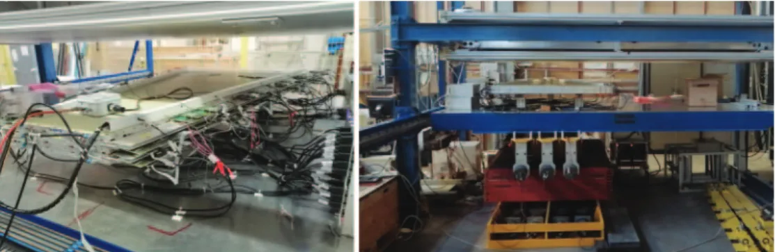
Fig. 8. – Pictures of the Cosmic Ray Stand of the Frascati INFN National Laboratories. Two scintillator planes are used as trigger and are located below the chamber under test.
Fig. 9. – Efficiencies as a function of the precision coordinate (x) for the four layer and 2D map of the efficiency for the first eta layer.
3.5. Efficiencies. – The modules need to be validated at the Cosmic Ray Stand to estimate the efficiency and gain uniformity. The experimental setup is shown in fig. 8 and consists of two scintillators, placed below the chamber, for the trigger coincidence separated by 35 cm of iron and achieving a trigger rate of 50 Hz. Using a self-tracking method (each chamber is composed by four layers) the track can be reconstructed and the efficiencies as a function of the extrapolated position can be measured as shown in fig. 9. The low efficiency regions (yellow) in fig. 9 are due to known problem on the front-end electronics. All the assembled modules fulfil the requirements in terms of average efficiencies.
4. – Conclusions
Micromegas chambers will be used after Long Shut-down 2 for precision tracking in the NSWs of the ATLAS experiment. The technology is mature for use in extremely complex environments such as high pseudorapidity zones in LHC experiments. The SM1 INFN group was the first to build the 2 prototypes micromegas and is now in full production and validation phase of the final chambers. A complete validation procedure has been prepared, which has been applied to the first 14 built chambers. According to the time schedule, in 2020 only one wheel will be installed and in the first year of Run-3 ATLAS will operate with an asymmetrical situation with a NSW in only one endcap region and the old detectors in the other region. The second one will be mounted in the first EYETS (End-of-Year-Extended-Technical-Stop) at the end 2021.
REFERENCES
[1] Giomataris Y., Rebourgeard P., Robert J. and Charpak G., Nucl. Instrum.
Methods A, 376 (1996) 29.
[2] Alexopoulos T. et al., Nucl. Instrum. Methods A, 617 (2010) 161. [3] Alexopoulos T. et al., Nucl. Instrum. Methods A, 640 (2011) 110.
[4] ATLAS Collaboration, New Small Wheel, Technical Design Report, CERN-LHCC-2013-006 (2013).
![Fig. 2. – The New Small Wheel subdivision in small (S) and large (L) sectors [4].](https://thumb-eu.123doks.com/thumbv2/123dokorg/8311602.131752/2.892.275.620.205.382/fig-new-small-wheel-subdivision-small-large-sectors.webp)