2017
Publication Year
2020-08-25T13:19:10Z
Acceptance in OA@INAF
The ASTRI SST-2M prototype for the Cherenkov Telescope Array: status after the
commissioning phase of the telescope
Title
CANESTRARI, Rodolfo; GIRO, Enrico; SIRONI, GIORGIA; ANTOLINI, ELISA;
Fermino, Carlos Eduardo; et al.
Authors
10.1117/12.2276767
DOI
http://hdl.handle.net/20.500.12386/26797
Handle
PROCEEDINGS OF SPIE
Series
10399
Number
PROCEEDINGS OF SPIE
SPIEDigitalLibrary.org/conference-proceedings-of-spie
The ASTRI SST-2M prototype for the
Cherenkov Telescope Array: status
after the commissioning phase of the
telescope
Canestrari, Rodolfo, Giro, Enrico, Sironi, Giorgia, Antolini,
Elisa, Fermino, Carlos Eduardo, et al.
Rodolfo Canestrari, Enrico Giro, Giorgia Sironi, Elisa Antolini, Carlos Eduardo
Fermino, Dino Fugazza, Carmelo Gargano, Federico Russo, Salvatore
Scuderi, Gino Tosti, Giovanni Pareschi, G. Marchiori, A. Busatta, E. Marcuzzi,
I. Folla, "The ASTRI SST-2M prototype for the Cherenkov Telescope Array:
status after the commissioning phase of the telescope," Proc. SPIE 10399,
The ASTRI SST-2M prototype for the Cherenkov Telescope Array:
status after the commissioning phase of the telescope
Rodolfo Canestrari
*a, Enrico Giro
b, Giorgia Sironi
a, Elisa Antolini
c, Carlos Eduardo Fermino
d, Dino
Fugazza
a, Carmelo Gargano
e, Federico Russo
f, Salvatore Scuderi
g, Gino Tosti
cand Giovanni
Pareschi
a, for the CTA ASTRI Project
h,iand G. Marchiori
l, A. Busatta
l, E. Marcuzzi
land I. Folla
ma
INAF-Osservatorio Astronomico di Brera – Via Bianchi, 46 23807 Merate (Lc) Italy
bINAF-Osservatorio Astronomico di Padova – Vicolo Osservatorio, 5 35122 Padova (Pd) Italy
c
Università di Perugia – Via A. Pascoli 06123 Perugia (Pg) Italy
d
Universidade de Sao Paulo Instituto Astronomico e Geofisico – R. do Matao, 1226 Sao Paulo
eINAF-IASF Palermo – Via Ugo la Malfa, 153 90146 Palermo (Pa) Italy
f
INAF-Osservatorio Astrofisico di Torino – Strada Osservatorio 20, 10025, Pino Torinese (To)
gINAF-Osservatorio Astrofisico di Catania – Via Santa Sofia, 78 95123 Catania (Ct) Italy
h
http://www.brera.inaf.it/astri/
ihttp://www.cta-observatory.org/
l
EIE GROUP Srl, via Torino 151A, 30172 Mestre-Venezia
mGalbiati Group Srl, Via Cà Bianca Pascolo, 26 - 23848 Oggiono (Lc)
ABSTRACT
ASTRI SST-2M is an imaging atmospheric Cherenkov telescope developed by the Italian National Institute of Astrophysics (INAF) in the framework of the Cherenkov Telescope Array (CTA) project as an end-to-end prototype for the Small Size array. Large-, medium-, and small-sized telescopes will compose the CTA observatory that represents the next generation of imaging atmospheric Cherenkov telescopes and will explore the very high-energy domain from a few tens of GeV up to few hundreds of TeV.
The ASTRI SST-2M telescope has been installed at the INAF-Catania observing station at Serra La Nave, on Mt. Etna (Sicily, Italy) in September 2014. In these 3 years of open-air operations the telescope has been commissioned and its opto-mechanical performance is now well understood. The apparatus was made ready to host its main scientific instrument, the camera with Silicon-Photomultiplier based detectors.
This contribution is a status report on the complete ASTRI SST-2M telescope assembly including the electro-mechanical structure and the optical system.
Keywords: imaging atmospheric Cherenkov telescope, very high-energy gamma rays, wide-field aplanatic telescope, CTA, ASTRI, segmented optics
1. INTRODUCTION
Ground-based gamma-ray astronomy is a young field in astrophysical and astroparticle Physics research with enormous scientific potential. The possibility of astrophysical measurements at teraelectronvolt (TeV) energies was demonstrated only recently, in 1989, with the detection of a clear signal from the Crab nebula above 1 TeV using the Whipple 10 m
Imaging Atmospheric Cherenkov telescope (IACT) [1]. Since then, astronomy with IACTs has evolved and a new scientific discipline has been established. Up to now we have the detection of more than 150 sources. The current major arrays of IACTs: H.E.S.S. [2], VERITAS [3], and MAGIC [4], have demonstrated the huge physics potential at these energies as well as the maturity of the detection technique. Many astrophysical source classes have been established, some with many well-studied individual objects, but there are indications that the known sources represent the tip of the iceberg in terms of both individual objects and source classes.
The Cherenkov Telescope Array (CTA) will be the major global observatory for very high energy gamma-ray astronomy over the next decade and beyond [5]. The scientific potential of CTA is extremely broad: from understanding the role of relativistic cosmic particles to the search for dark matter. In fact, CTA is an explorer of the extreme universe, probing environments from the immediate neighborhood of black holes to cosmic voids on the largest scales. Covering a huge range in photon energy from 20 GeV to 300 TeV, CTA will improve with respect to current instruments on all aspects of performance. Wider field of view and improved sensitivity will enable CTA to survey hundreds of times faster than current instruments. The angular resolution will approach 1 arc-minute (at high energies) allowing detailed imaging of a large number of gamma-ray sources. An improvement of nearly two order-of-magnitude in the collection area makes CTA a powerful instrument for time-domain astrophysics. The CTA will transform our understanding of the high-energy universe and will explore questions in physics of fundamental importance. Moreover, as a key member of the suite of new and upcoming major astroparticle physics experiments and observatories, CTA will exploit synergies with gravitational wave and neutrino observatories as well as with classical photon observatories. Combining CTA data with those from other instruments in a multi-wavelength and multi-messenger approach will lead to a deeper understanding of the broad-band non-thermal properties of gamma-ray emitters.
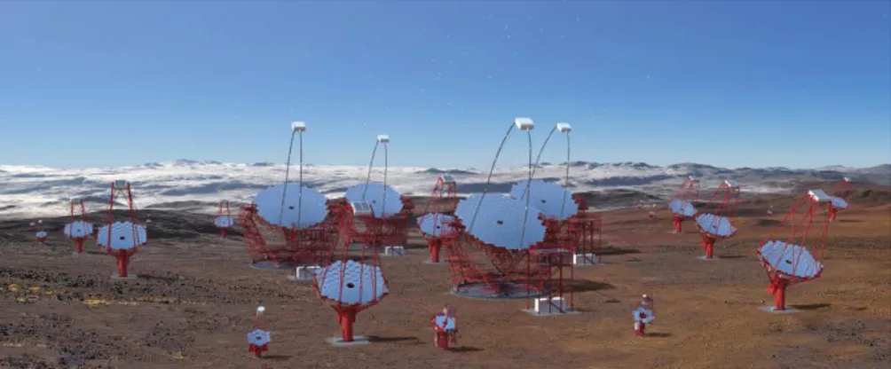
The CTA will be operated as an open, proposal-driven observatory, with all data available on a public archive after a pre-defined proprietary period. The Observatory will operate arrays on sites in both hemispheres to provide full sky coverage and will hence maximize the potential for the rarest phenomena such as very nearby supernova, gamma-ray bursts or gravitational wave transients. With 99 telescopes on the southern site and 19 telescopes on the northern site, flexible operations will be possible, with sub-arrays available for specific tasks. At the southern site three classes of telescopes are planned to be installed: Small Size Telescopes (SST), Medium Size Telescopes (MST) and Large Size Telescopes (LST), see Figure 1. In the northern site, only MST and LST are envisaged.
Concerning the SST class of telescopes, different options are available for the implementation of the CTA observatory. The Italian National Institute for Astrophysics (INAF) leads one of these; the ASTRI SST-2M is the end-to-end telescope prototype developed in this context. Others options under study can be found in [7] and [8].
The ASTRI SST-2M prototype is the basis of the ASTRI telescopes that have been proposed for the CTA SSTs sub-array. For the early stages of the CTA southern site implementation, a set of nine ASTRI telescopes has been proposed. This proposal is a collaborative effort led by INAF along with Institutes from Italy, Brazil, and South-Africa [9].
The ASTRI SST-2M end-to-end telescope prototype is installed in Italy at the INAF observing station located in Serra La Nave (Mt. Etna, Sicily), 1740 m a.s.l. [10]. In the following sections we give an overview of the opto-mechanical solution and optical layout of the ASTRI SST-2M telescope and then we report some of the results coming out from the on-site optical tests campaign.
C E U
i
co O CO 0 12 -1 11-10-
9-
8-
7- 6- 5-4 -' 0 - Nominal D80Angular size of the pixel
1 2 3
field angle
ri
4 5
2. THE OPTICAL SUB-SYSTEM
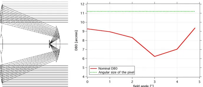
The ASTRI SST-2M telescope makes use of an optical layout derived from the proposal made by Schwarzschild (1905) and Couder (1926) and firstly suggested for use in IACT in 2007 by Vassiliev [11]. This design allows better correction of aberrations at large incident angles even for small focal ratios and hence facilitates the construction of compact telescopes. This optical system is an attractive solution for the SST class of telescopes since it enables good angular resolution across the entire field of view of almost 10º, and allows to reduce the focal length and therefore the physical pixel. This has a direct impact on the overall size of the camera that will be very compact. Having typical lateral dimension of few millimeters, the silicon photomultiplier (SiPM) sensors are the perfect solution to realize such a system [12]. The solution adopted by the ASTRI SST-2M prototype [13] ensures that more than 80% of the light emitted by a point source (so called D80) is collected within the dimensions of a pixel over the full field of view of the telescope. The mirror profiles are aspheric with substantial deviations from the main spherical component. The ASTRI SST-2M optical system design has a plate scale of 37.5 mm/º, an angular pixel size of approximately 0.19º and an equivalent focal length of 2150 mm. This setup delivers a corrected field of view of 10.5º in diameter and a mean value of the effective area of about 5 m2. The calculations to obtain these results take into account the mechanical solution adopted for the implementations such as mirrors segmentation and reflectivity, structural obstructions and others. Figure 2 shows the telescope optical layout and its performance in terms of D80.
The resulting telescope is a compact system, with a primary mirror (M1) diameter of 4.3 m, a secondary mirror (M2) diameter of 1.8 m, a primary-to-secondary distance of 3.1 m and distance from camera to secondary of 0.52 m.
Figure 2: (left) Optical layout for the Schwarzschild-Couder solution adopted by ASTRI SST-2M. (right) Comparison between D80 obtained by the design of the optical system and the angular pixel size.
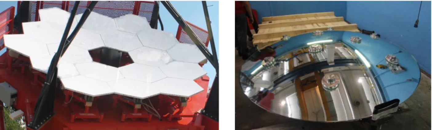
For the ASTRI SST-2M telescope, the primary mirror (M1) is designed as a set of 18 hexagonal-shaped panels of 850 mm flat-to-flat size. These segments are distributed around three concentric rings. In order to reproduce the aspherical optical profile of M1, the segmented panels for each of the three coronas have different profiles. Moreover, each ring has a different radial distance from the telescope vertex. The result is that the M1 behaves like an aspherical monolithic mirror. However, the Point Spread Function (PSF) corresponding to each of the three rings composing M1 is different. Consequently, the optical quality of each panel has to be verified with respect to its corresponding corona. The ensemble of the 18 mirror segments assembled together to compose the entire M1 is shown on the left panel of Figure 3.
The M2 mirror is instead built on a monolithic substrate of 1.8 m diameter with an f-number of only 0.597. The substrate for this mirror is a thick glass shell of 19 mm bent to the desired radius of curvature with a thermal process. Surface measurements done by means of a coordinates measuring machine at the bending factory return a peak-to-valley error of
4'
J
41PP'
the order of 250 μm rms. On the rear side of the mirror, metallic pads have been glued in order to offer a clear mechanical interface point to the load spreaders of the mechanical system as shown in the right panel of Figure 3.
Details about the technology and the manufacturing of the mirrors can be found in [14], [15] and [16].
Figure 3: (left) Primary mirror of the ASTRI SST-2M prototype, a plastic film protects the mirrors. (right) The secondary mirror of the ASTRI SST-2M prototype with interfaces seen from its rear side.
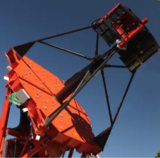
The train of optical components is kept in position by the optical support structure (see Figure 4). It can be divided into the following main components: the M1 dish and segment support assembly, the mast and central tube, the M2 backup structure with load spreader assembly. Optical baffles and shields to counteract snow and wind loads are also installed. The M1 dish is a flat structure based on a T-ribbed plate. It is composed of two asymmetric halves connected to each other by means of plugs located along the mid plane. The connection line is orthogonal to the elevation plane. The interfaces with each mirror segment of M1 are on the front side of the dish. Spacers provide the gross positioning of the mirror segments. While the mirror supports sit atop the spacers and are designed to individually sustain the mirror segments by means of motorized actuators. The actuators can move each M1 mirror segment in order to compensate for any small alignment error in the primary reflector. This assembly is called Active Mirror Control and dedicated software is running the subsystem.
The mast and central tube are the key elements to position the secondary mirror and the detector of the telescope in their nominal position. The mast is a quadrupod with radial eccentric bracing system. It connects the central tube, the M1 dish and the M2 backup structure. This solution shows improved performance in comparison with simpler configurations, including a lower obstruction for off-axis rays. Finally yet importantly, this configuration allows some freedom in adjusting the relative distances between the optical components (namely M1, M2 and the detector) in case of minor problems that could arise during manufacturing, or slight modifications to the optical design that might be shown to be necessary from in-field tests.
A structural assembly consisting of an arrangement of tapered I-beams and a central triangular prism supports the M2. The tapered beams connect the four-flanged tubes that are bolted to the mast, while the triangular prism supports the whiffletrees load-spreaders.
The fine positioning of the secondary mirror is delegated to three axial actuators. They are located between the load-spreaders and the triangular prism. These actuators enable mirror positioning both in terms of linear translation along the optical axis (for focus adjustments) and of tilting around the two other orthogonal axes (for optical alignment purposes). The lateral component of the various playing loads (e.g., mirror weight, wind and ice) is supported by three lateral constraints obtained with three tie rods.
An optical baffle around the M2 mirror is applied in order to limit the amount of night sky background reaching the detector because, in the Schwarzschild-Couder layout, the camera is facing the sky all the time.
Figure 4: The optical supporting structure of the ASTRI SST-2M during its assembly at the telescope site. In the image the M1 dish, the mast and central tube, the M2 backup structure with the baffles.
3. THE ELECTRO-MECHANICAL TELESCOPE SUB-SYSTEM
The ASTRI SST-2M telescope adopts an altitude-azimuth mount in which the azimuthal motion will permit a rotation range of ±270º. The mirror dish is mounted on a fork support which allows rotation around the elevation axis from 0º to +91º. Fixed on the mirror dish is the mast structure that supports the secondary mirror and the camera. In order to balance the torque due to the overhang of the optical tube assembly with respect to the horizontal rotation axis, counterweights are also suspended from the mirror dish.
The mount component provides the support for the optical support structure. It includes three main structural elements: the base, the azimuth bearing and the azimuth fork structure.
The main base structure has a truncated cone shape. It is fixed to the foundation and the azimuth fork is installed on the upper part of the base through the azimuth bearing, by virtue of which azimuth relative rotation between the two elements is possible. The truncated cone shape guarantees the best compromise between proper transmission of the load of the telescope to the foundation and the lowest mass of the structure. Several ribs are soldered onto the base in order to obtain the best load distribution, reduce the possibility of deformation and increase the stiffness of the whole structure. The internal cavity of the base can be accessed through a door in order to perform all needed operations on the azimuth encoder, cables, azimuth switches etc., and to safely carry out alignment and maintenance procedures on those devices.
The azimuth axis uses a custom slewing bearing manufactured from a standard one in order to satisfy the stiffness requirements of the application. The outer ring of the slewing bearing is provided with a rack in order to permit azimuth axis rotation by means of two pinions driven through a chain of reduction stages by the azimuth servomotors. The inner ring, which is fixed to the azimuth fork lower flange, is provided with a proper slot in order to allow the installation of the azimuth strip encoder.
The azimuth fork main structure is one of the key structural elements; it provides support and interfaces to a list of subcomponents. The main ones are the following: the azimuth and elevation bearings, the azimuth motor drives, the elevation actuator drive, the azimuth and elevation stow pins, the azimuth and elevation limit switches. Finally, the azimuth fork supports the electrical cabinets, in which all the telescope control hardware and communication electronics is installed. Two motors located at 180º to each other power the azimuth axis motion. Each motor is provided with two reduction stages and transmits motion to the mechanical axis through a pinion mounted on the second reduction gearbox and coupled to the slewing-bearing. The two motors are controlled in differential torque mode in order to eliminate backlash and hence guarantee good motion accuracy under all operational conditions. The reduction gearbox system used is the SEW R97R57 with SEW CM71S brushless motors. One of the two motors is also equipped with a brake and a back shaft. The brake can also be released manually in order to be able to move the azimuth axis with a battery powered drill mounted on the back shaft of the motor in case of power failure or when emergency situations arise.
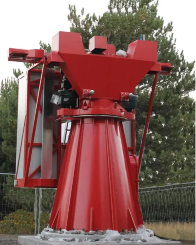
Figure 5 is a picture of the mount subsystem taken during the initial phases of the telescope installation at its host site. The motion in Elevation axis is possible with a preloaded ball screw jack driven by a brushless motor. The preloaded ball screw jack is fixed by means of two hinges, one located on the top of the ball screw itself and the other installed on its body. This allows us to provide motion of the M1 dish and thus of all the structure supporting the M1 reflecting segments. The ball screw is fully deployed or retracted when the elevation angles are close to the horizon or zenith positions respectively. To protect the ball screw from environmental agents when it is deployed, a bellows is installed; since the screw is passing through the jack, a protection tube is used when the ball screw is fully retracted.
The servomotor used for this application is a SEW CM90L equipped with brake and hand release, in order to provide safe operations and avoid accidents to people and hardware. The brake is able to stop any motion. Similarly to the solution adopted for the azimuth motion, the coupled use of the hand release with the portable power drill on the back shaft allows the movement of the ball screw jack.
Both azimuth and elevation motor assemblies are controlled by the servo drive electronics, which are installed in one of the telescope cabinet: the high power cabinet. The software is installed on a dedicated industrial PC that acts as a PLC, drives the motors and controls the telescope.
The telescope structure is also provided with two stow-pins that keep the telescope parked and in safe position when engaged.
The unbalanced torque related to the dish mass, due to the overhang of the elevation structure with respect to the rotation axis, is compensated by means of two counterweights connected to the dish.
Figure 5: The mount structure of the ASTRI SST-2M during its assembly at the telescope site. On top of the base the azimuth fork is already installed together with the electrical cabinets.
4. THE TELESCOPE CONTROL SUB-SYSTEM
The ASTRI SST-2M telescope prototype is a standalone system. To work it needs only proper network and power connections. In fact, all the control hardware is installed on board the telescope inside the two electrical cabinets mounted on the azimuth fork: the High Power Cabinet (HPC) and the Low Power Cabinet (LPC). The cabinets themselves are thermally controlled by a dedicated control system. They are protected from dust and water. The block diagram of the control hardware showing the main links is displayed in the left panel of Figure 6.
The HPC hosts all the high power hardware such as the motor drivers which are the high power electronics that deliver power to the motors. The HPC is connected to the 400 V power grid and, via an ethercat cable, to the LPC to ensure the communication between the servo drivers and the Telescope Control Hardware (TCH) system.
The LPC high-level architecture includes the basic communication connections with the TCH and the major power lines that ensure the correct power distribution within the cabinet. The LPC has a low bias source (220 V) that powers all its devices. There is also a power supply able to transform the 220 V into all voltages requested for different integrated devices. In addition, in order to guarantee the maximum safety and reliability of the telescope during operations, a UPS is also installed and some of the most critical hardware installed in the LPC is powered through the UPS line. For a high-level diagram see the right panel of Figure 6.
r To Control Roam Optical Drawer i J Telescope Switct MCI Telescope Health Contra Unit (THCU) Telescope Control Unit (TCU) Safety PLC Opto Transciever
Ethercat Low POWER CABINET r
Servo Drive
High POWER CABINET
400V
Telescope Control Cabinet
r -Opto Transciever - - _ -Ethercat O Power Supply Under UPS Power Supply Telescope Control Hardware .TCS. (TCU, AMCU. THMU.
Safety PLC) E(nemet toOMbrt 220V 220V Conditioning Monitor 24V
The hardware and software components on-board the telescope are responsible for managing all the operations related to the telescope monitoring and control. The TCH assembly includes all the electronics and software parts needed to operate the telescope system. Among the others, to drive the telescope to any accessible sky position during the commissioning, testing and observing phases; to guarantee safe function to the telescope itself and to the operators; to bring and keep the optical system aligned. The main TCH components are: the Telescope Control Unit (TCU), the safe PLC and Telescope Health Control Unit (THCU), the Active Mirror Control Unit (AMCU). The TCU, THCU and AMCU are industrial PCs (Beckhoff) installed in the LPC that offer high reliability and reduced maintenance. These systems, together with the Cherenkov Camera and the devices needed for communication, are fed through the UPS line.
The TCU manages the major servo systems (elevation and azimuth). It is in charge of the sky coordinates acquisition and conversion to the telescope axis coordinates; calculates the trajectory for the telescope motion; transfers the telescope axis coordinates to the drive system and performs the readout of the azimuth and elevation encoders for controlling the position loops.
The THCU is in charge of monitoring the interlock chain through a dedicated safety PLC, which is compliant with the international standard for safety. Depending on the kind of switch trigger, the Safety PLC takes an action on the system and this action is reported to the THCU and then to the operator. The THCU is also in charge of switching on and off all the devices integrated in the telescope and, at the same time, is able to monitor their status.
The AMCU is in charge of the control and monitoring of the movements of the mirrors. The communication between the AMCU and the control board of each actuator is via a CAN bus line.
The THCU, TCU and AMCU are connected to the telescope network switch and are thus remotely accessible. The slow control of the camera and the control of the auxiliary components are also routed through this switch. The telescope internal network is connected through a fiber optic bundle to the main networking devices installed in the server/control room. Details about the hardware and software design architecture of the telescope control sub-system can be found in [18] and [19].
Figure 6: (left) Block diagram of the control hardware in the telescope and its connection paths. (right) Low power cabinet architecture. Only power and communication lines (e.g. Ethernet) are shown.
5. THE AUXILIARIES SUB-SYSTEM
The ASTRI SST-2M telescope prototype is equipped with auxiliary devices to support operations and safety of the telescope itself. A weather station and an all-sky camera are deployed external to the telescope [20]. Other devices (Pointing Monitor Camera, Sky Quality Meter, temperature sensors and lightning protection system) are mounted onto the telescope structure.
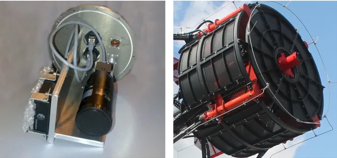
The Pointing Monitor Camera (PMC), see Figure 7, is a CCD camera with dedicated optics and a large field of view of about 2.8ºx2.1º. This camera is mounted on the secondary mirror support system. It points to the sky along the direction of the telescope’s opto-mechanical axis. It is used to track the flexures of the telescope’s mechanical structure. The PMC provides snapshots of the sky at regular interval of time to check the mechanical pointing of the telescope during the observing runs. Using an astrometric pattern recognition algorithm on the recorded images we can reconstruct the pointing with high precision.
A network of 23 temperature sensors is installed on the ASTRI SST-2M telescope prototype. The sensors are PT100 gauges in a 4-wire connection layout; their readout system is based on the Agilent 34980A multifunction switch/measure mainframe. These sensors map the entire telescope system, monitoring the thermal gradients that can in principle strongly degrade some of the telescope performances. For instance, the PSF of the telescope can undergo distortions as well as the effective pointing of the system can result deviated.
The telescope structure is protected by a specific lightning protection system embedded in the mechanical design. This protective cage is electrically connected to the metallic grid embedded in the concrete of the foundation. The foundation is connected by means of dedicated metallic rods to the equipotential ring that circles the installation site. This system guarantees the needed protection level to the telescope.
Figure 7: (left) The Pointing Monitor Camera during the integration phase. The PMC support hosts also the sky quality meter (right) The PMC mounted on the support of the secondary mirror of the ASTRI SST-2M telescope prototype.
-S-600 c ó 400 o aô.
t
É 200 o °.-, 0.0ÇASTRI SST -2M azimuth movement - open loop
- Actual velocity - Actual position - Commanded position - Position error Y 0 I 20 I ' 40 I ' 60 I 80 ' 100 I 120 I 140 I ' 160 I 180 Time [s] 0.0--0.5 -; -1.0-L-1.5 ó
-;
2.0 -W -2.5-1oo-ASTRI SST -2M elevation movement - open loop
ó 80 - - Actual positionActual velocity
l c 60 -- Commanded postion Position error ó 40 > 20 - 0-ó 4 Ó t, 0
..
4 0 5 10 15 20 i i i 25 30 35 40 45 50 55 Time [s] 60 6. STATUS OF THE TELESCOPE SYSTEMSince its installation and inauguration on September 2014 the ASTRI SST-2M telescope prototype has entered into its commissioning phase. During this 3-year period of time different teams of the ASTRI Collaboration and of the Industries have carried out on-field tests on both the hardware and the software components of the system. The telescope is now ready and it is starting the commissioning phase of the overall system including camera, data acquisition, data analysis and archiving [21].
In the following sections we report the results achieved during the commissioning phase of the telescope.
6.1 Electro-mechanical structure
The electro-mechanical structure has been intensively studied and its parameters optimized to get the best performance. This activity consisted in a series of functional tests to assess the low level functionality of the telescope as well as a deep understanding of the dynamic behavior of the azimuth and elevation motion systems.
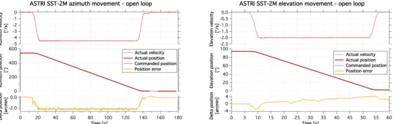
The functional tests concern for instance the electrical functionality of all the limit switches, the maximum velocities and accelerations achievable, the braking range upon emergency stop, the axes motion range amplitude. After the tests, the telescope shows a wide operation range both on azimuth and elevation. The total usable range during observation is 542.23° in azimuth and 91.78° in elevation. Despite these motions have happened in open-loop, the telescope shows also a good trajectory precision. In fact, the azimuth error is limited to about 2 arcmin while the elevation error remains below ±3.5 arcmin. A summary of these results is shown in Figure 8. A detailed study about the behavior of the mechanical system can be found in [22].
Figure 8: Full range movement for azimuth (left) and elevation (right) axes. The plots show the maximum velocities (red slim line), the motion range (red and black lines) and the positioning errors during the run (orange line).
Studying the Eigen frequencies of the mechanical structure and the tracking capability we have accessed the dynamic behavior of the telescope.
In particular, the tracking errors have been evaluated by looking at the trajectory’s coordinates generated by the telescope motion controller and the actual position of the telescope retrieved by the encoders reading during the run. This test has shown a typical behavior having tracking errors of the order of 5.5 arcsec in azimuth and 11.5 arcsec in elevation over a 10 minutes run. The evaluation of the tracking accuracy has been repeated looking at sky sources and acquiring images with the PMC. From those images we extract the sky coordinates of the sources. The result obtained after pointing and tracking the BL Lac source for 10 minutes is shown in Figure 9. The images acquired with the PMC have undergone the astrometric pattern recognition algorithm to retrieve the sky coordinates and have been compared with the coordinates coming from the encoders readings. A clear offset of about 150 arcsec is visible; we think it is due to an error which occurred during the initial setpoint operation. Taken out this contribution, it remains an error of about 3 arcsec rms. A drift
42.40 42.38 -,-, 42.361-rn a) -o V W ' 42.34 42.32 -42.30 , , i , 330.80 330.82 330.84 330.86 330.88 RA (dec)
on the tracking of about 20 arcsec is also measured. This result has been achieved in a mild night with a wind of 10 km/hr but in absence of gusts.
Figure 9: On-sky tracking precision of the telescope as accessed by comparing the coordinate retrieved by the PMC (triangle) and those coming from the encoders reading (diamond). A small drift in the tracking is also observed (black line)
Despite the good performance achieved by the telescope we spotted out some issues with both the azimuth and elevation motion system that imposed a correction of the design. In particular the elevation jack was found introducing an oscillation out of the specification. The re-machining of the nut and the removal of a ferrule was needed to bring the elevation axis in specification. On the other hand, the azimuth drive system seems to suffer the prolonged stop imposed by the strong winter season we experience at the installation site and it needed to be early replaced. An accurate analysis of these failures is ongoing and an upgrade of the design is being studied. At the time being, to spot in advance this type of failures a conditioning monitoring system will be installed shortly. The system is based on sensors, basically accelerometers and strain gauges that will measure vibrations induced by the mechatronic systems. In fact, by analyzing the data it is possible to derive information on the health of the mechatronic system (e.g., structure, gears, bearings, drives). Many systems available on the market can perform such analyses with negligible effort, and can perform trend analysis and plan for preventive maintenance. The current baseline system is based on Beckhoff module EL3632. This module is able to work at 50KHz, suitable for vibration analysis.
6.2 PSF and mirror reflectivity
Beginning in October 2016, we successfully performed a series of tests of major impact to demonstrate the optical performances of the telescope: in particular we measured the behavior of the PSF as a function of the telescope elevation, position on the field of view and temporal stability over a large timescale period.
A camera with CCD detectors was specifically designed and built to perform such verifications. Two configurations are available: the large size CCD placed in the center of the telescope focal plane and the small size CCD that can be moved into different positions of the focal surface. The large size CCD (37 x 37 mm) corresponds to 1° x 1°, while the small size CCD (27 x 18 mm) can be positioned at 0º, ±1.5º, ±3º and ±4.5º off-axis angles. With these high resolution CCDs the PSF
1.2 1.0 69 0.8 a a> C 0.6 U U w 0.4 0.2 0.0 Polaris - H R603 .-. Deneb Capella 1 2 3 4 5 Radial distance [mm]
is oversampled allowing appreciating its fine structures. This camera is mounted at the telescope’s focal surface in place of the Cherenkov camera.
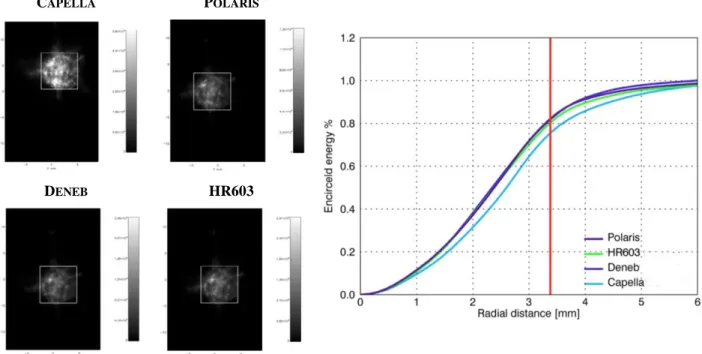
The stability of the PSF of the ASTRI SST-2M telescope prototype has been tested as function of the telescope elevation. The objective of the test was to verify that the stiffness of the structure allows avoiding a continuous re-alignment of the mirrors during observations. The output of the test is a table reporting the D80 values of the PSF for different elevations of the telescope. Images of 4 sources at different elevation were acquired (see the left panel in Figure 10). For each source at least 5 images were acquired. For each image the encircled energy was calculated (see the right panel in Figure 10) and the D80 values are reported in Table 1. The D80 of Capella is a little worse because of the observing conditions. The measurements show that the PSF does not suffer variations from the elevation of the telescope. This confirms the analysis made during the design of the telescope.
CAPELLA POLARIS
DENEB HR603
Figure 10 (left) Example of images acquired on the 4 different sources used during the test. The white square boxes correspond to the Cherenkov pixels size. (right) Plot of the encircled energy as function of the radial distance.
Table 1 Values obtained from the 4 sources used during the evaluation of the stability of the D80 parameter versus the telescope elevation. SOURCE ELEVATION D80[º] Capella 36º 55’ 0.192 Polaris 37º 56’ 0.174 Deneb 60º 2’ 0.176 HR603 75º 4’ 0.178
5,1.
Tt-EP
hp L
I
The large field of view has been verified monitoring the value of the PSF at various off-axis angles [23]. The Polaris was observed by the ASTRI SST-2M telescope prototype (see Figure 11) with different offsets from the optical axis of the telescope. The recorded images have approximately the same angular size, each one from a different observational direction in the field of view (from 0 to 4.5 degrees from each side with respect to the central optical axis). In fact, for a Cherenkov telescope it is not necessary to have very fine imaging capability, in contrast to conventional optical telescopes. It should instead be able to see “reasonably well” across a wide field of view (much wider than that needed for optical astronomy), in order to determine the morphology of the showers responsible for the Cherenkov light emission and initiated by Cosmic Rays or Gamma Rays. These images show that the optical PSF of the telescope is approximately constant across the full field of view. This is the first time that conclusively demonstrates the viability of the Schwarzschild-Couder system [24].
Figure 11 The Polaris images observed by the ASTRI SST-2M telescope prototype at different viewing angles covering the entire field of view of the telescope. Alignment has been obtained at 3º. The white square boxes correspond to the Cherenkov pixels size.
We also measured the PSF temporal stability. The objective of the test was to verify that the stiffness of the structure allows avoiding frequent realignments. We report here two images of the Polaris (see Figure 12): the first acquired on October 2016, the second one acquired on March 2017. Nothing was changed in alignment parameters between the two acquisitions. Both images were taken with the telescope pointed on the selected source without tracking it. But the image taken on 2017 was acquired on a partially cloudy night, so the exposure time was longer than that of the other image. This results in a visible blurring of the image. Nevertheless, both the D80 parameter and the encircled energy curves are almost unchanged. Moreover, also the fine structures of the PSF are clearly constant with time. Variations between the two images are of the order of 0.1% for the encircled energy and 0.4 mm for the D80 parameter as reported in Table 2.
10 5 E E 0 r -5 -10 -5 0 X mm 5 1.28x16 1.07x10⁴ &56x10x 6.42x10'1 4.28x101 2.14x101
6:1
Figure 12 The two images of the Polaris acquired in October 2016 (left) and March 2017 (right). The square boxes correspond to the Cherenkov pixels size.
Table 2 Encircled energy and D80 parameter values obtained for the Polaris on two different nights at 6 month time distance.
DATE ENCIRCLED ENERGY D80[mm]
October 2016 83.75% 0.192
March 2017 83.86% 0.181
Concerning mirror reflectivity evolution, regular measuring campaigns have been performed so far to monitor the reflectivity for the primary and secondary mirrors. The surface of each mirror segment of M1 has been sampled with 9 measuring points over 3 diagonals. Concerning M2, the surface is sampled over 4 diagonals. Each diagonal has 9 measuring points. Measures are weighted for the probed mirror area and then averaged. The reflectivity values acquired at the manufacturing and after two years from the installation are show in Figure 13. The ageing effect is noticeably larger than expected from experience with similar coating. This can be attributed to the particularly aggressive environment where the telescope is sited. In fact, the Etna Mount is an active volcano and the eruptions are very frequent making the air locally dense of abrasive and corrosive dust and grains.
Figure 13 Mean reflectivity of the primary mirror of the ASTRI SST-2M telescope. (left) Reflectivity of the mirrors at the manufacturing (left) and after two year from installation (right).
7. CONCLUSIONS
This paper presents the status of the ASTRI SST-2M telescope prototype after almost three years from its installation at the site.
The telescope has been built and completed for the first time ever adopting the Schwarzschild-Couder configuration. This kind of telescope has never been realized until CTA, mainly due to technological difficulties. However, recent advances in technology (in particular for the realization of the primary and secondary mirrors) have made the implementation of this design practicable for the observation of Cherenkov light emitted by the atmospheric showers generated by cosmic gamma rays. It is also the first time that a Cherenkov telescope with two focusing mirrors has been completely characterized from the opto-mechanical point of view.
In particular the demonstration we give about the PSF across the large field of view of the telescope is of major impact for the project. This is an important result because it allows us to move immediately to the next step: to mount the Cherenkov camera aiming to observe Cherenkov light of atmospheric showers with the ASTRI SST-2M telescope.
ACKNOWLEDGMENTS
This work is supported by the Italian Ministry of Education, University, and Research (MIUR) with funds specifically assigned to the Italian National Institute of Astrophysics (INAF) for the Cherenkov Telescope Array (CTA), and by the Italian Ministry of Economic Development (MISE) within the “Astronomia Industriale” program. We acknowledge support from the Brazilian Funding Agency FAPESP (Grant 2013/10559-5) and from the South African Department of Science and Technology through Funding Agreement 0227/2014 for the South African Gamma-Ray Astronomy Programme. We gratefully acknowledge financial support from the agencies and organizations listed here:
http://www.cta-observatory.org/consortium_acknowledgments.
For the years 2015, 2016 and 2017 R. Canestrari, G. Pareschi and G. Sironi acknowledge partial support from the Grant Cariplo/Regione Lombardia ID 2014-1980/ RST under the project “Science and Technology at the frontiers of Gamma-Ray Astronomy with imaging atmospheric Cherenkov telescopes”.
REFERENCES
[1] Weekes T.C., et al., “Observation of TeV gamma rays from the Crab nebula using the atmospheric Cerenkov imaging technique,” Astrophysical Journal 342, 379 (1989)
[3] Holder J., et al., “Status of the VERITAS Observatory,” Contribution to AIP 1085, (2008) [4] Ferenc D., et al., “The MAGIC gamma-ray observatory,” NIM-A 553, 274-281 (2005) [5] Acharya B. S., et al., “Introducing the CTA concept,” Astroparticle Physics 43, 3-18 (2013)
[6] Galbraith W. and Jelly, J. V., “Light Pulses from the Night Sky associated with Cosmic Rays,” Nature 171, 4347 (1953)
[7] Dournaux J. L., et al., “GCT, an end-to-end SC telescope prototype for the CTA,” Proceeding SPIE 9908, 990648 (2016)
[8] Aguilar J. A., et al., “The Single Mirror Small Size Telescope (SST-1M) of the Cherenkov Telescope Array,” Proceeding SPIE 9906, 990636 (2016)
[9] Pareschi G., et al., “The ASTRI SST-2M prototype and mini-array for the Cherenkov Telescope Array (CTA),” Proceeding SPIE 9906, (2016)
[10] Maccarone M. C., et al., “The site of the ASTRI SST-2M telescope prototype,” Proceeding of the 33rd ICRC, (2013)
[11] Vassiliev V., Fegan S. and Brousseau P., “Wide field aplanatic two-mirror telescopes for ground-based γ-ray astronomy,” Astroparticle Physics 28, 10-27 (2007)
[12] Catalano O., et al., “The camera of the ASTRI SST-2M prototype for the Cherenkov Telescope Array,” Proceeding SPIE 9147, 91470D (2014)
[13] Canestrari R., et al., “The Italian ASTRI program: an end-to-end dual-mirror telescope prototype for Cherenkov light imaging above few TeV,” Proceedings of the 32nd ICRC 0895, (2011)
[14] Canestrari R., et al., “Cold-shaping of thin glass foils as novel method for mirrors processing. From the basic concepts to mass production of mirrors,” Optical Engineering 52, 051204-1 (2013)
[15] Canestrari R., et al., “The ASTRI SST-2M prototype for the Cherenkov Telescope Array: manufacturing of the structure and the mirrors,” Proceeding SPIE 9145, 91450M (2014)
[16] Rodeghiero G., at al., “Qualification and testing of a large hot slumped secondary mirror for Schwarszchild-Couder Imaging Air Cherenkov Telescopes,” PASP, (2016)
[17] Marchiori G., et al., “The ASTRI SST-2M prototype for the next generation of Cherenkov Telescope Array: prototype technologies, goals, and strategies for the future SST,” Proceeding SPIE 9145, 91450L (2014) [18] Antolini E., et al., “Mount control system of the ASTRI SST-2M prototype for the Cherenkov Telescope Array,”
Proceeding SPIE 9913, 99131J (2016)
[19] Tanci C., et al., “Software design and code generation for the engineering graphical user interface of the ASTRI SST-2M prototype for the Cherenkov Telescope Array,” Proceeding SPIE 9913, 99133X (2016)
[20] Leto G., et al., “The site of the ASTRI SST-2M telescope prototype: atmospheric monitoring and auxiliary instrumentation,” Proceedings of AtmoHEAD, (2013)
[21] Maccarone M. C., for the CTA ASTRI Project, “ASTRI for the Cherenkov Telescope Array,” Proceeding of the 35th ICRC 855, (2017)
[22] Canestrari R., et al., “The ASTRI SST-2M prototype for the Cherenkov Telescope Array: opto-mechanical test results,” Proceeding SPIE 9603, 960303 (2015)
[23] Giro E., et al., “First optical validation of a Schwarzschild Couder telescope: the ASTRI SST-2M Cherenkov telescope,” A&A submitted (2017)
[24] CTA Press Release, 11 November 2016