U
NIVERSITÀ DEGLI
S
TUDI DI
N
APOLI
F
EDERICO
II
Dottorato di Ricerca in Ingegneria Industriale
XXXI Ciclo
Experiments and Simulations of Hybrid
Rocket Internal Flows and Material
Behaviour
Coordinatore:
Prof. Michele Grassi
Tutor:
Prof. Raffaele Savino
Co-tutor:
Dott. Carmine Carmicino
Candidato:
Ing. Di Martino Giuseppe
Daniele
Table of Contents I
T
ABLE OF
C
ONTENTS
Table of Contents ... I List of Figures ... V List of Tables ... IX Abstract ... XCHAPTER 1. Hybrid Rocket Propulsion: state of the art ... 1
1.1 Introduction to hybrid rocket engines ... 1
1.1.1 Advantages of hybrid rockets ... 2
1.1.2 Historical perspective and potential applications of hybrid rocket propulsion technology ... 4
1.2 Hybrid rocket combustion mechanism ... 7
1.2.1 The model of Marxman and Gilbert ... 7
1.2.2 Combustion of liquefying fuels... 9
1.3 CFD modelling of hybrid rocket internal ballistics ... 11
1.4 Summary of original contributions of the present dissertation on hybrid rocket internal ballistics modelling ... 13
CHAPTER 2. Low erosion materials for propulsion application ... 15
2.1 Rocket nozzle operating conditions ... 15
2.2 Materials for rocket nozzle applications ... 17
2.3 The C3HARME research project for development and testing of UHTCMC materials ... 19
2.4 Summary of the contributions of the present dissertation on advanced materials for propulsion application ... 21
Table of Contents
II
3.1 Experimental facilities ... 23
3.1.1 The lab-scale motors ... 23
3.1.2 Feeding line ... 25
3.1.3 Signal measurements and data acquisition system ... 26
3.2 Firing data reduction technique ... 28
3.3 Experimental firing test ... 30
3.3.1 Test cases with polymeric fuels ... 30
3.3.2 Test cases with paraffin-based fuel grain ... 34
CHAPTER 4. Modelling of hybrid rockets internal ballistics ... 36
4.1 Introduction to the definition of the numerical model for hybrid rockets simulation ... 36
4.2 Physical and numerical models for gaseous flowfield simulation ... 37
4.2.1 Turbulence model ... 38
4.2.2 Combustion model ... 40
4.2.3 Thermodynamic and transport properties ... 42
4.3 Computational domain and boundary conditions ... 43
4.4 Gas/fuel surface interface modelling ... 44
4.4.1 The case of polymeric fuels ... 45
4.4.2 The case of liquefying fuels ... 49
4.5 Port diameter update with time for the transient simulation of the fuel grain consumption ... 53
CHAPTER 5. Numerical results of hybrid rockets internal ballistics simulation ... 55
5.1 Numerical results in the case of polymeric fuels ... 55
5.1.1 Steady simulations ... 55
5.1.2 Grid sensitivity analysis ... 60
Table of Contents
III
5.2 Numerical results in the case of liquefying fuels ... 69
5.2.1 Effect of the additional entrainment regression rate component .. 69
5.2.2 Grid sensitivity analysis ... 73
5.2.3 Effect of vaporization temperature and entrainment parameter ... 75
5.2.4 Comparison between numerical results and experimental data .... 78
CHAPTER 6. Characterization of UHTCMC in hybrid rocket propulsion environment ... 81
6.1 Design of prototypes and experimental setup ... 81
6.1.1 Experimental setup for free-jet test ... 81
6.1.2 Setup for test of nozzle throat inserts ... 83
6.2 Numerical models for the characterization of the flowfield around test articles ... 84
6.2.1 One-dimensional model for chamber and nozzle conditions simulation ... 85
6.2.2 CFD model for the simulation of the flow field around test articles ... 86
6.3 Experimental characterization of UHTCMC samples in free jet conditions ... 89
6.3.1 UHTCMC samples ... 89
6.3.2 Test conditions ... 90
6.3.3 Experimental results ... 94
6.4 Experimental characterization of UHTCMC nozzle throat insert ... 102
6.4.1 UHTCMC samples ... 102
6.4.2 Test conditions ... 103
6.4.3 Experimental results ... 105
Table of Contents
IV
Acknowledgments ... 111 Bibliography ... 112
List of Figures
V
L
IST OF
F
IGURES
Figure 1.1. Schematic of classical hybrid rocket engine. ... 1
Figure 1.2. Boundary layer combustion mechanism for hybrid rockets. ... 8
Figure 1.3. Liquid layer instability and droplet entrainment mechanism (Ref. [28]). 10 Figure 2.1. Molar fractions of the combustion products in rockets with different propellants [44]. ... 16
Figure 2.2. (a) Segmented nozzle (after removal of the converging outer element), (b) ceramic throat, (c) details of the ceramic throat showing radial cracks [45]. ... 19
Figure 2.3. Design of the test articles for C3HARME experimental campaign for characterization of UHTCMCs in propulsion application [59]. ... 20
Figure 3.1. 200 N-class hybrid rocket engine schematic. ... 23
Figure 3.2. 1 kN-class hybrid rocket engine layout. ... 25
Figure 3.3. Test feeding lines schematic. ... 26
Figure 3.4. Tescom ER3000 pressure controller scheme. ... 26
Figure 3.5. Rocket exhaust plume (Test HDPE-1). ... 31
Figure 3.6. Sequence of pictures of the hybrid rocket exhaust nozzle after the firing test (Test HDPE-1). ... 31
Figure 3.7. Operating pressures vs time. ... 32
Figure 3.8. Rocket exhaust plume (Test P-4) ... 35
Figure 4.1. An example of the computational grid for the 200 N-class engine ... 44
Figure 4.2. Schematic representation of the i-th node displacement components. .... 54
Figure 5.1. Results of the steady-state numerical simulation in the case of Test HDPE-1. ... 56
Figure 5.2. Results of the steady-state numerical simulation in the case of Test ABS-1. ... 57
Figure 5.3. Regression rate distributions evolution in the firing with the axial-nozzle injector. ... 59
Figure 5.4. Numerical regression rate profiles calculated with different refined computational grids (Test HDPE-1). ... 61
List of Figures
VI
Figure 5.5. Temperature contour plot with overlapped streamlines (top half) and
mixture fractions isolines (bottom half) at different times. ... 64
Figure 5.6. Regression rate distributions evolution in the firing test. ... 65
Figure 5.7. Fuel-grain port local diameter evolution in the firing test. ... 66
Figure 5.8. Comparison between the measured and calculated local regression rate for Test HDPE-2. ... 68
Figure 5.9. Comparison between the results with and without considering the entrainment. ... 70
Figure 5.10 Numerical results in the case of paraffin fuel ... 72
Figure 5.11. Numerical results in the case of HDPE fuel ... 73
Figure 5.12. Numerical error versus grid size. ... 74
Figure 5.13. Effect of the vaporization temperature on the axial profiles of the regression rate and its components. ... 76
Figure 5.14. Effect of the entrainment parameter on the axial profiles of the regression rate and its components. ... 77
Figure 5.15. Regression rate axial profile (Test 4): comparison between numerical results and experimental data. ... 78
Figure 5.16. Comparison between numerical results and experimental data in terms of average regression rate as a function of the oxidizer mass flux. ... 80
Figure 6.1. Nominal design of UHTCMC samples for free jet tests. Dimensions are in mm. ... 82
Figure 6.2. Set-up for free-jet test. The area within the red circle in the left picture is zoomed in the right picture. ... 82
Figure 6.3. Design of segmented nozzle with UHTCMC nozzle throat insert. Dimensions are in mm. ... 84
Figure 6.4. Computational grid for the simulation of the free reacting jet exiting from the rocket nozzle. ... 88
Figure 6.5. Computational grid for the simulation of the flow through the rocket nozzle. ... 89
Figure 6.6. Temperature distribution in the free-jet test. ... 92
List of Figures
VII
Figure 6.8. Erosion rates of UHTCMC samples in free jet test: comparison between
Ti3SiC2 based samples and ZrB2/SiC based samples. ... 94
Figure 6.9. Pictures of sample TSC-SF-1 before (top) and after (bottom) the test. .. 95
Figure 6.10. Pictures of sample ZBSC-LF-1 before (top) and after (bottom) the test. ... 96
Figure 6.11. Pictures of sample TSC-SF-2 after the test. ... 96
Figure 6.12. Pictures of sample ZBSC-LF-2 after the test. ... 96
Figure 6.13. Thermal histories of the samples TSC-SF-1 and ZBSC-LF-1 tested in Test condition 1FJ. ... 97
Figure 6.14. Pictures of test on TSC-SF-1 sample, at beginning (left) and end (right) of the test (Test Condition 1FJ). ... 98
Figure 6.15. Pictures of test on ZBSC-LF-1 sample, at beginning (left) and end (right) of the test (Test Condition 1FJ). ... 98
Figure 6.16. IR thermal images of TSC-SF-1 sample, taken every 0.5 s, starting from immediately before the temperature jump. ... 99
Figure 6.17. Temperature radial profiles, measured by the thermo-camera, on sample TSC-SF-1 front surface at different time instants, around the temperature jump. .... 99
Figure 6.18. Thermal histories of the TSC-SF-2 and ZBSC-LF-2 samples tested in Test condition 2FJ. ... 100
Figure 6.19. Thermographic images of sample ZBSC-LF-2. ... 100
Figure 6.20. Erosion rates of UHTCMC samples in free jet test: comparison between short-fibers-based and long-fibers-based samples. ... 101
Figure 6.21. Thermal histories of the ZBSC-LF-2 and ZBSC-SF-1 samples tested in Test condition 2FJ. ... 102
Figure 6.22. Temperature distribution through rocket nozzle. ... 105
Figure 6.23. O2 mass fraction distributions through rocket nozzle. ... 105
Figure 6.24. Nozzle throat erosion rates. ... 106
Figure 6.25. Microscopic pictures of graphite nozzle throat. ... 107
Figure 6.26. Microscopic pictures of ZBSC-SF-TI. ... 107
List of Figures
VIII
Figure 6.28. Theoretical and measured chamber pressures vs operating time for tests in conditions 2TI. ... 108
List of Tables
IX
L
IST OF
T
ABLES
Table 2.1. Solid and hybrid rocket nozzle operating conditions [44]. ... 15
Table 3.1. Experimental data of firing test cases with polymeric fuels. ... 33
Table 3.2. Experimental data of firing test cases with paraffin-based fuel grains performed with the 200 N-class hybrid rocket. ... 34
Table 4.1. Values of SST model constants [67]. ... 40
Table 4.2. Computational domain dimensions. ... 44
Table 4.3. Solid fuels properties and rate constants. ... 47
Table 4.4. Paraffin fuel properties. ... 50
Table 5.1. Computed average pressure in the aft-mixing chamber and deviation with experimental data. ... 60
Table 5.2. Results of grid sensitivity analysis on the spatially averaged regression rate. ... 62
Table 5.3. Computed averaged parameters and deviation with respect to experimental data. ... 67
Table 5.4. Results of grid sensitivity analysis on the spatially averaged regression rate components. ... 74
Table 5.5. Vaporization temperature and entrainment parameter effect on the average regression rate. ... 77
Table 5.6. Computed regression rate deviations from experimental data. ... 80
Table 6.1. C2H4 – O2 reaction system. ... 87
Table 6.2. UHTCMC samples for free jet test. ... 90
Table 6.3. Nominal test conditions for free jet tests. ... 90
Table 6.4. Conditions at sample location estimated with the CFD simulations of the free-jet test. ... 91
Table 6.5. UHTCMC nozzle throat inserts. ... 103
Table 6.6. Nominal test conditions throat insert testing. ... 103
Abstract
X
A
BSTRACT
In the last decade a significant and ever growing interest has been addressed towards hybrid rocket propulsion, which offers the best-of-both-worlds by leveraging the favourable aspect of both traditional solid and liquid systems. Among the numerous advantages which characterize hybrid rockets, the most attractive ones are the re-ignition and throttling capabilities combined with the possibility of embedding environmentally sustainable propellants and, of the utmost importance, their intrinsic safety and lower operational costs. Moreover, hybrid rockets yield a better specific impulse than solid propellant rockets and a higher density impulse than liquids, which make them a promising technology in a number of space missions.
The widely recognized potentialities of the hybrid rocket warrant the renewed research efforts that are being devoted to its development, but the state-of-the-art of this technology still presents a number of challenging issues to be solved.
A first fundamental task is the definition of suitable models for the prediction of the motor internal ballistics and performance. In particular, rocket performance is governed by the rate at which the fuel is gasified, i.e. by the fuel regression rate, as this latter determines the total mass flow rate and the overall oxidizer-to-fuel mixture ratio, which, for a given chamber pressure, control the motor thrust and the ideal specific impulse. For a given fuel, regression rate is basically limited by the heat flux input to the solid grain, which mainly depends on the thermo-fluid-dynamics in the combustion chamber. This latter is significantly influenced by several geometrical parameters, such as, for example, the oxidizer injection configuration or the grain port shape. Furthermore, the recent efforts aimed at overcoming the main drawback of the hybrid rockets, which is the low regression rate of conventional polymeric fuels, have been focused on the development of new paraffin-based fuels, characterized by a consumption mechanism presenting additional complex phenomena compared to that of conventional polymers. Their intrinsic characteristic is the onset of a thin liquid layer on the fuel grain surface, which may become unstable, leading to the lift-off and entrainment of fuel liquid droplets into the main gas stream, increasing the fuel mass
Abstract
XI
transfer rate. This phenomenon is strongly susceptible to the fuel composition, its manufacturing process and the obtained thermo-mechanical properties as well as to the engine operating conditions, which makes the prediction of the regression rate and combustion chamber internal ballistics even harder than in the case of a pure polymer. In this framework, computational fluid dynamics of hybrid rocket internal ballistics is becoming a key tool for reducing the engine operation uncertainties and development cost, but its application still presents numerous challenges due to the complexity of modelling the phenomena involved in the fuel consumption mechanism and the interaction with the reacting flowfield, for both the cases of classical polymeric and liquefying paraffin-based fuels. A research effort is therefore of major importance in order to cover the lacking aspects and obtain quantitatively accurate results.
Another challenge for the hybrid rocket technology development is the optimization of the design of thermal insulations. The inner surface of the exhaust nozzle, through which the flow is accelerated to supersonic conditions producing the required thrust, is the most critical in this sense, as it is subjected to the highest shear stress and heat fluxes in a chemically aggressive environment. These severe conditions usually lead to removal of surface material due to heterogeneous reactions between oxidizing species in the hot gas and the solid wall. Because of the material erosion, there is an enlargement of the nozzle throat section and a consequent decrease of rocket thrust, with detrimental effects over the motor operation. Thus, the requirement that dimensional stability of the nozzle throat should be maintained makes the selection of suitable rocket nozzle materials extremely hard. In recent years, Ultra-High-Temperature Ceramics (UHTC) and Ultra-High-Ultra-High-Temperature Ceramic Matrix Composites are the subject of considerable interest as innovative materials for rocket application, but still need to be properly characterized. Experimental testing along with computational fluid dynamic (CFD) simulations are, thus, both needed to improve the design and the current performance prediction capabilities of such propulsion systems. In this framework, the University of Naples is involved in the European project C3HARME – Next Generation Ceramic Composites for Combustion Harsh
Abstract
XII
industries, which aims at the design, manufacturing and testing of new-class high-performance UHTCMC for near-zero erosion rocket nozzles.
In the present work, the above-mentioned challenges are dealt with taking a combined experimental/numerical approach to improve understanding of the interaction between the gaseous combusting flow typical of hybrid rocket engines and the surface of solid materials involved in their operation, with a special focus to the fuel grain present in the combustion chamber, with the aim of predicting its consumption mechanism, and the exhaust nozzle inner surface, with the aim of identifying and validating new-class UHTCMC materials with improved erosion and structural resistance to the severe conditions experienced in particular in the throat region.
In particular, the first main objective of the present work is the definition of proper computational thermo-fluid-dynamic models of the hybrid rocket internal ballistics, including a dedicated gas/surface interface treatment based on local mass, energy and mean mixture fraction balances as well as proper turbulence boundary conditions, which can properly model the physical fuel consumption mechanism in both the cases of polymeric and liquefying fuels. For the validation of the computational models, a number of experimental test cases, obtained from static firing of laboratory scale rockets, have been performed at the Aerospace Propulsion Laboratory of University of Naples “Federico II” and successively numerically reconstructed. The comparison between the numerical results and the corresponding experimental data allowed validating the adopted model and identifying possible future improvements.
Then, the research activities for the characterization of new-class UHTCMC materials are presented and discussed. This part of the work was mainly focused on an extensive experimental campaign for the characterization of new-class UHTCMC materials. In particular, first preliminary tests on small samples exposed to the supersonic exhaust jet of a 200N-class hybrid rocket operated with gaseous oxygen burning cylindrical port High-Density PolyEthylene (HDPE) fuel grains have been carried out for a fast characterization and a preliminary screening of the best candidates for the final applications. After that UHTCMC nozzle throat inserts has been manufactured and experimentally tested to verify the erosion resistance and evaluate
Abstract
XIII
the effects on the rocket performance by comparison with those obtained in similar operating conditions employing a graphite nozzle. The experimental activities are supported by simplified low-computational-cost numerical simulations, whose main objectives has been the prediction of the complex flow field in the hybrid rocket combustion chamber and the thermo-fluid dynamic conditions on the material. Future research activities will be then focused to the further development of the numerical models with the extension of the treatment for the gaseous flow/solid surface interaction in order to get a deeper insight on the new materials behaviour.
CHAPTER 1. Hybrid Rocket Propulsion: state of the art
1
CHAPTER 1. H
YBRID
R
OCKET
P
ROPULSION
:
STATE OF THE ART
1.1 Introduction to hybrid rocket engines
Hybrid rockets are chemical propulsion engines whose concept has been known since the early 20th century [1], in which fuel and oxidizer are separated in different physical states. In the classical system configuration (see Figure 1.1), hybrid rockets usually accommodate a prechamber ahead of the fuel grain, and an aft-mixing chamber, downstream of it; fuel is stored in the combustion chamber in the solid state, and a liquid or gaseous oxidizer is injected into one or multiple ports obtained in the solid fuel grain. The latter is usually made by simple classical polymers, such as high density polyethylene (HDPE), hydroxyl-terminated polybutadiene (HTPB), and polymethylmethacrylate (PMMA), polymers with metal additives to improve the density impulse, or, more recently, paraffin waxes.
Figure 1.1. Schematic of classical hybrid rocket engine.
When the two propellants are ignited, a diffusive flame is formed in the boundary layer developing in the grain port, relatively far from the fuel surface, and it is fed, from the outer side, by the oxidizer, which is transported from the free stream by turbulent diffusion mechanisms, and, from the inner side, by the products of fuel pyrolysis that is sustained by the flame itself; the combusted mixture then expands through an exhaust nozzle generating the required thrust.
CHAPTER 1. Hybrid Rocket Propulsion: state of the art
2
Performance of these engines is governed by the rate at which the fuel is gasified, i.e. by the fuel regression rate 𝑟̇, as this latter determines the total mass flow rate and overall oxidizer-to-fuel mixture ratio 𝑂𝐹, which, for a given chamber pressure, control the motor thrust and the ideal specific impulse 𝐼𝑠𝑝.
1.1.1 Advantages of hybrid rockets
In the last decade a significant and ever growing interest has been addressed towards hybrid rocket propulsion thanks to its numerous advantages [2] compared to traditional solid and liquid systems.
1.1.1.1 Safety
The primary reason for interest in hybrid is the non-explosive nature of the design, which lead to safety in both operation and manufacture [3, 4]. In fact, in liquid bipropellant rockets, a pump leak or tank rupture can bring the oxidizer and the fuel together in an uncontrolled way resulting in a large explosion, while, in solid propellant rockets, the fuel and oxidizer are already mixed and held together in a polymer binder, so that cracks or imperfections can cause uncontrolled combustion and explosion. In hybrid propellant rockets the fuel and oxidizer are intimately separated and the design is less susceptible to chemical explosion. The fuel can be fabricated at any conventional commercial site, realizing a large cost saving.
1.1.1.2 Re-ignition and throttling capability
One of the critical issues of solid fuel rockets is the impossibility of shut down and re-ignition, i.e. once the engine is ignited there is no possibility to control or to stop the ignition, until the fuel grain is completely burned. On the contrary hybrid rocket engines can be throttled by modulating the oxidizer flow rate, to optimize the trajectory during atmospheric launch and orbit injection, and thrust termination/restart is simply accomplished by turning off and on the oxidizer flow rate.
With respect to liquid bipropellant rockets, hybrid rockets require one rather than two liquid containment and delivery systems, reducing the complexity and improving the reliability of the system. Throttling control is simpler because it alleviates the
CHAPTER 1. Hybrid Rocket Propulsion: state of the art
3
requirement to match the momenta of the dual propellant streams during the throttling operation.
1.1.1.3 Environmental sustainability
Oxidizers and fuels used in hybrid rocket engines produce usually less threat to health and environmental safety. For example Hydrazine and its derivatives, which are widely used as propellants in liquid rockets, are highly corrosive, toxic and carcinogens.
The products of combustion in hybrid rockets are environmentally benign compared with conventional solids that generally use perchlorate-based oxidizers. In fact, solid rocket combustion products contain acid-forming gases such as hydrogen chloride (HCl). In addition, there are concerns about the effects of low levels of environmental perchlorate.
1.1.1.4 Theoretical specific and density impulse
Hybrid rockets yield a higher specific impulse than solid propellant rockets. In fact, the theoretical specific impulse of a hybrid rocket is more appropriately compared to a bipropellant liquid than a solid. This is because the oxidizers are the same and the solid fuels are hydrocarbons with energy content similar to kerosene.
However, hybrid solid fuel density are typically 15-20% greater than the density of liquid kerosene, so hybrid rockets yields higher density impulse than liquids. Furthermore, the fact that the fuel is in the solid phase makes it very easy to add performance-modifying materials. For example, the addition of aluminium powder produces a substantial increase in fuel density, increases the theoretical 𝐼𝑠𝑝 and shifts the peak 𝐼𝑠𝑝 to lower values of the oxidizer-to-fuel ratio. This leads to a reduced liquid feed system and tank size, producing better performance.
In conclusion, the above discussed features make hybrid engines a promising technology in a number of space missions, opening to safer and more flexible space vehicle launching and manoeuvring [5, 6, 7].
CHAPTER 1. Hybrid Rocket Propulsion: state of the art
4
1.1.2 Historical perspective and potential applications of
hybrid rocket propulsion technology
The hybrid rocket concept has been around for more than eighty years. The first liquid propellant rocket launched by the Soviet Union was actually a hybrid that used liquid oxygen (LOX) and gelled gasoline. The rocket was designed by Mikhail Tikhonravov in 1933 and built by a team from the Group for the Study of Reaction Motors (GRID) that was headed by the famous Sergei Korolev. The first flight reached an altitude of 1500 m using a 500 N class motor that burned for 15 s.
The earliest effort in the U.S. occurred at the Pacific Rocket Society and at General Electric, beginning in the late 1940s and continuing up to 1956. But early hybrid rocket development began in earnest when flight test programs were initiated both in Europe and in the U.S. in the 1960s. European programs in France and in Sweden involved small sounding rockets, whereas the American flight programs, largely sponsored by the U.S. Military Force, were target drones that required supersonic flight in the upper atmosphere for up to 5 minutes. Furthermore, in the late 1960s the small size hybrid rockets started to be scaled to large size motors by the Chemical Systems Division of United Technologies, which investigated motor designs that could produce the high thrust required for space launch vehicles. Anyway, although several successful firings were performed during those years, it was recognized that the volumetric fuel loading efficiency was too low mainly because of the low regression rate.
Interest in the hybrid was revived again in the late 1970s, when concerns aroused about safety storage and handling of the large solid propellant segments of the Shuttle booster. Then, beginning in the late 1980s, two significant hybrid efforts occurred. One was the formation of the American Rocket Company (AMROC), an entrepreneurial industrial company entirely devoted to the development of large hybrid boosters based on LOX and HTPB. The second, with encouragement from NASA, was the formation of the Hybrid Propulsion Industry Action Group (HPIAG), composed of both system and propulsion companies devoted to exploring the possible use of hybrids for launch booster applications. Again, both efforts ran into technical stumbling blocks, caused by the low regression rate of HTPB fuel.
CHAPTER 1. Hybrid Rocket Propulsion: state of the art
5
Several hybrid propulsion programs were initiated also in the late 1980s and in the 1990s. The most remarkable one was the Hybrid Propulsion Demonstration Program (HPDP), whose main objective was the design and fabrication of a 250000 lb thrust test bed.
The most successful flight of a hybrid rocket occurred in 2004 when the reusable manned spaceplane SpaceShipOne reached an altitude of 100 km for the second time in a 1-week period, using a four-port HTPB fuelled motor and nitrous oxide (N2O)
oxidizer.
Throughout this history, the fundamental issue of low regression rate inherent in polymeric fuels was the main drawback for the hybrid rocket development, but it was clear that if a significantly higher burning rate could be realized for the hybrid motor, the difficulties mentioned above could be greatly reduced and a smaller, more efficient motor could be designed. This deficiency was recognized early on, and many attempts were made to increase the regression rate.
In particular, the research activities carried out at Stanford University, beginning in 1997, led in the mid-2000s to the development of a class of liquefying fuels, including paraffin-based fuels, characterized by very high regression rate, ensuring good performance at low cost, availability, low environmental impact. These results renewed the interest in hybrid rocket technology as a promising propulsive solution for important innovative missions.
Several market studies, starting from early 2000 allowed performing trade-off analyses for the identification of the most suitable space/aerospace application for hybrid rockets, with a particular interest in the framework of mass access to space. Four main markets can be identified for such technology, each one with different requirements in terms of performance and cost, which are listed in the following.
Sub-orbital flight vehicles can be seen as the first enabling building block. In particular, large growth potential for space tourism as a business concept (Ref. [8, 9]) suggests the need for improvement in propulsion technologies, which would reduce the service price. Therefore, strategies for space propulsion cost reduction rely essentially on two approaches. The first approach is based on the use of lower cost and higher performance rocket engines, like hybrid rocket
CHAPTER 1. Hybrid Rocket Propulsion: state of the art
6
engines. The second approach involves the use of innovative high performance fuels, such as paraffin-based fuels. The interest of hybrid rocket applications in sub-orbital systems is increasing in both commercial and public funded projects. Commercial vehicles include Virgin Galactic SpaceShipTwo, Copenhagen Suborbitals Tycho Brahe and Whittinghill Aerospace mCLS: these are or will be powered by hybrid rocket motors [10].
Launch vehicles upper stages could represent an effective market entrance of hybrid propulsion system, since this application is characterized by relatively low barrier and several potential advantages would derive from hybrid technology. An example of public effort in this direction involves the HYPROGEO EU-Funded project in the Horizon 2020 framework, related to the development of an hybrid rocket for launch vehicles upper stages, under the leadership of Airbus Defence and Space SAS.
Nano/microsatellite launch vehicles. Considering the 2013 nano/ microsatellite launch services report [11], it is possible to assume that nano/microsatellites launch is a growing market. Furthermore, the historical analysis suggests that the current launch vehicle capacity will not be able to satisfy the future demand, in particular considering the increasing number of requests for micro/nanosatellites. In order to exploit the increase in market demand, it will be of great importance to put in place specific strategies. In this scenario, hybrid launch vehicles for small payloads can be effectively developed using the knowledge established with sub-orbital applications. This is an important step in the direction of overcoming the historical perspective of nano/microsatellites as secondary payload only. The advantages of such dedicated launch systems are: low cost, flexibility, low environmental impact and orbit/time specificity. Launch vehicles lower stages/boosters. The application of hybrid rocket
motors to launch vehicles lower stages and boosters is the most challenging scenario. Lower launch vehicles stages are characterized by very high thrust (magnitude order of several MN), required to reach escape velocity and lift-off of the launch vehicle. This extreme performance level requires a very large system. In such geometries, scale-up combustion phenomena can occur, which
CHAPTER 1. Hybrid Rocket Propulsion: state of the art
7
can significantly affect the engine behaviour. Low-scale to large-scale effects involve combustion stability, fuel grain mechanical resistance and non-homogeneous fuel consumption issues.
1.2 Hybrid rocket combustion mechanism
One of the fundamental problem in the design of a hybrid rocket is to accurately predict the fuel regression-rate, as a function of time and position along the surface of grain, since, as mentioned before, this is the main parameter governing the engine performance. Of course, this problem can be addressed only by a proper modelling of the hybrid rocket internal ballistics, which depend on different complex and interacting physical phenomena, on the engine configuration and on the fuel and oxidizer physical nature.
Many theories have been developed over the years in order to describe the hybrid combustion mechanism, but often they lack some important aspects or failed in the prediction of experimental results [12, 13, 14].
1.2.1 The model of Marxman and Gilbert
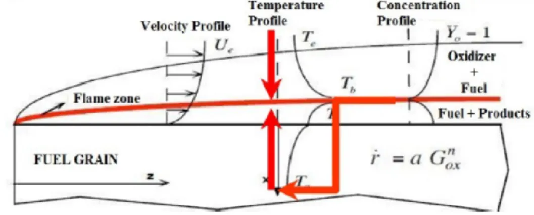
The most reliable hybrid combustion model for classical polymeric fuels was developed in 1963 by Marxman and Gilbert [15, 16] and it is still the starting point of design calculations and experimental comparisons. This model is based on the concept of diffusion flame, anticipated before, according to which the combustion reaction occurs in a thin region inside the developing boundary layer through diffusive mixing between vaporized oxidizer flowing through the port and fuel evaporating from the solid surface. Thus, the flame zone can be considered as temperature and mixture composition discontinuity (see Figure 1.2). Typically the chemical kinetics in the reaction zone are much faster than the relatively slow diffusion processes which provides the fuel and the oxidizer to the flame, thus the flame is said to be diffusion-limited.
CHAPTER 1. Hybrid Rocket Propulsion: state of the art
8
Figure 1.2. Boundary layer combustion mechanism for hybrid rockets.
According to this model, the fuel regression rate is proportional to the wall heat flux as
𝜌𝑓𝑟̇ = (𝜌𝑣)𝑤 =𝑞̇𝑤
ℎ𝑣 (1.1)
where 𝜌𝑓 is the solid fuel density, (𝜌𝑣)𝑤 is the gaseous mass flux at the fuel wall, 𝑞̇𝑤
is the heat flux to the wall and ℎ𝑣 is the effective fuel vaporization heat, i.e. the energy per unit mass needed to evaporate fuel from the initial solid fuel temperature.
Considering the simpler configuration of a uniform oxidizer flow on a solid fuel slab, assuming unit Lewis and Prandtl numbers and applying the Reynolds analogy, the previous equation can be manipulated obtaining the following relationship between the fuel regression rate and the total axial mass flux 𝐺
𝜌𝑓𝑟̇ = 0.036 𝐺 𝑅𝑒𝑥−0.2 𝐵0.23 (1.2)
where 𝑅𝑒𝑥= 𝐺𝑥/𝜇 is the local Reynolds number and 𝐵 is the so called blowing factor. More generally, in order to overcome the slab fuel configuration hypothesis and the further complexity due to the total mass flux dependence on the regression rate itself, the regression rate law is simply expressed in the form
CHAPTER 1. Hybrid Rocket Propulsion: state of the art
9
𝑟̇ = 𝑎𝐺𝑜𝑥𝑛 (1.3)
where 𝐺𝑜𝑥 is the oxidizer mass flux in the fuel grain port and 𝑎 and 𝑛 are constant
mainly depending on the propellants and on the system configuration and are usually determined experimentally. Eq. (1.3) represents the fact that, in marked contrast to solid rockets, the regression rate of a hybrid is insensitive to the chamber pressure, while, because of the diffusion-limited nature of the combustion process, it is primarily governed by turbulent mixing and heat transfer in the boundary layer, which in turn depend on the mass flux.
1.2.2 Combustion of liquefying fuels
As described in the previous section, fuel regression of classical polymers is determined by the ratio between the heat flux to the surface and the heat of phase change, thus it is limited by the heat and mass transfer mechanisms occurring from the flame to the fuel wall; blowing of fuel from the surface decreases the velocity gradient at the wall and the convective heat transfer for the so-called blocking effect [15]. Owing to this “counter-balance” between heat flux and blowing, hybrid rocket motors operating with polymeric fuels usually suffer from the problems associated with low regression rate, which hinder the widespread application of such propulsion systems.
Several strategies have been suggested to mitigate this shortcoming, such as, among the most common ones, the design of multi-port grains for which, despite the slow regression, a high thrust level can be obtained; the design of injection systems inducing recirculating [17, 18] or swirling oxidizer flows [19, 20]; and the addition of metal additives or solid particles, which mostly raise the density impulse with a minor effectiveness on the regression rate [21]. Yet, all of these methods lead to an increase of the system complexity and associated cost without producing major improvements of the engine overall performance [22].
Researchers at Stanford University [23] have demonstrated that a much more effective method for enhancing regression rate is to use propellants that form a melt layer at the combustion surface. These are usually non-polymerized substances that liquefy on heating. An obvious class includes liquids or gases at standard conditions,
CHAPTER 1. Hybrid Rocket Propulsion: state of the art
10
which are frozen to form solids (that is, solid cryogenic hybrids). However it is clear that the same internal ballistic behaviour can be experienced by materials that are solids at standard conditions if they form a melt layer at the combustion surface. Paraffin-based fuels belong to the latter class [24].
Compared to conventional polymers, the consumption mechanism of this class of fuels, known as liquefying fuels, is basically different and allows for significantly larger regression rate. Karabeyoglu et al. [23] have shown that these fuels display, indeed, regression rates up to 3-4 times higher than those achieved with traditional hybrid fuels. Referring to Figure 1.3, their intrinsic characteristic is the onset of a thin liquid layer on the fuel grain surface, which may become unstable. In fact, due to the low viscosity and surface tension, it is affected by a hydrodynamic instability of the Kelvin-Helmholtz type [25, 26] driven by the oxidizer flow injection, which leads to the lift-off and entrainment of fuel liquid droplets into the main gas stream, increasing the fuel mass transfer rate. This characteristic behaviour has been experimentally investigated showing the formation of roll waves and droplets in the tests carried out at atmospheric pressure, and filament-like structures along the fuel grain in the tests run at elevated pressures [27].
Figure 1.3. Liquid layer instability and droplet entrainment mechanism (Ref. [28]).
CHAPTER 1. Hybrid Rocket Propulsion: state of the art
11
This mass transfer mechanism does not depend on heat transfer and raises the fuel mass flow without entailing the blocking effect determined by gaseous fuel blowing. As a result, the overall regression rate can be considered composed by two fractions, one determined by classical fuel vaporization, and the other by the liquid entrainment. The entrainment phenomenon is strongly susceptible to the fuel composition, its manufacturing process and the obtained thermo-mechanical properties as well as to the engine operating conditions [29], which makes the prediction of the combustion chamber internal ballistics even harder. Hence, on the one hand, designers need to characterize the fuel with extended experimental campaigns and, on the other, carry out rocket static firings to measure the achieved engine performance.
1.3 CFD modelling of hybrid rocket internal
ballistics
Affordable and reliable computational models, capable to simulate the thermo-fluid-dynamic field in the rocket combustion chamber, are the subject of considerable interest recently, as they are aimed to become an efficient tool both in the system design process and in the performance analysis stage for reducing the engine operation uncertainties and development cost.
In fact, the classical theories, starting from Marxman’s work described in Section 1.2.1, elaborated to predict the regression rate of pyrolyzing fuels, are all based on the assumption of a turbulent boundary layer with chemical reactions occurring in the burning of a fuel slab in an oxidant gas flow and, therefore, are unable to reproduce the oxidizer injection effects, which may have a non-negligible impact even in standard motors [17]. The analytical models subsequently developed for liquefying fuels, such as the one in Ref. [23], are essentially modifications of the classical hybrid boundary-layer combustion theory for the entrainment mass transfer from the fuel grain, and consequently present the same limits as the original theory.
In this context, computational fluid dynamic (CFD) approaches to the solution of flowfield in the hybrid propellant rocket chamber have been considerably developed
CHAPTER 1. Hybrid Rocket Propulsion: state of the art
12
recently [30, 31, 32]; most of the effort has been addressed to classical non-liquefying fuels, which, however, involve numerous complexities due, for example, to the interactions among fluid dynamics, oxidizer atomization and vaporization, mixing and combustion in the gas phase [19], nozzle thermochemical erosion [33], particulate formation, and radiative characteristics of the flame [34].
A common strategy is solving the Reynolds Averaged Navier-Stokes (RANS) equations, with suitable turbulence closure and combustion models. In particular, justified by the fact that chemical and fluid dynamic characteristic times are much shorter than the regression rate time scale, steady-state solution of RANS equations is generally sought [35]. An acceptable method to study the hybrid rocket internal ballistics can be, therefore, simulating the flowfield at different times in the motor firing by considering the fuel port geometry evolution [36]. Nevertheless, a single numerical simulation is often performed on the chamber geometry drawn at the time-space averaged port diameter [36, 37]. To the authors’ knowledge, in the competent literature, even when analyses have been performed at several stages of the motor firing, the grain inner diameter has been always considered uniform down the port; in other words, the axial non-uniformity of the regression rate has been usually neglected and the port diameter has been updated with a spatially-averaged regression rate value. Moreover, the definition of a suitable and computational cost-effective strategy for liquefying fuels poses further complications related to the modeling of the melting layer dynamics and of the liquid entrainment phenomenon. In principle, to successfully simulate the paraffin-fuel consumption, two non-trivial tasks have to be accomplished, that are modeling, first, the melted fuel entrainment from the grain surface, and, second, the transformation of the melted fuel into gaseous species participating in the combustion process. These demanding efforts have probably discouraged researchers, so that usually drastic simplifications are introduced, such as giving the regression rate calculation away by assuming it from experiments [38, 39], or limiting the analysis to one-dimensional integro-differential models [40]. In other cases, observing that under the hybrid rocket chamber characteristic conditions the melted paraffin wax is in the supercritical state (thus surface tension vanishes and the sharp distinction at droplets surface between gas and liquid phases disappear), the melted layer brake up and
CHAPTER 1. Hybrid Rocket Propulsion: state of the art
13
subsequent liquid paraffin injection in the flowfield is disregarded, supposing that the entrainment is part of the turbulent mixing process [41]. However, in general, all the existing models are not successfully validated displaying still significant deviations from experimental data, which in some cases are around 25%. Hence, a research effort is definitely of major importance in order to obtain quantitatively accurate results.
1.4 Summary of original contributions of the present
dissertation on hybrid rocket internal ballistics
modelling
In the research activities described in the present dissertation, a combined experimental/numerical effort has been spent for a better understanding of the consumption mechanism of fuel grains of different classes. The main objectives is the definition, the application and the validation, by comparison with specifically collected experimental data, of dedicated CFD models for the simulation of the thermo-fluid dynamic flow field inside the combustion chamber of hybrid rockets.
In particular, the work started from the definition of a simplified model apt to simulate the thermo-fluid-dynamic field in a hybrid rocket, in which however fuel regression rate was imposed decoupled from the actual flow field. The main purpose was to have a relatively fast tool to qualitatively analyse the effect of different parameters on the regression rate axial profile and to screen several oxidizer injectors based on the resulting motor performance. The results of such model are described in Ref. [42].
The CFD model has been successively elaborated in order to obtain quantitatively predictive capabilities also on the local regression rate of classical polymeric fuels, and on the corresponding chamber pressure, combustion efficiency and rocket performance. For this purpose, an improved treatment of the interface between the gaseous flow and the solid fuel surface has been defined, which is based on local mass, energy and species balances, with the application of proper turbulence boundary conditions and considering an additional equation for the fuel surface pyrolysis. Such
CHAPTER 1. Hybrid Rocket Propulsion: state of the art
14
a model has been applied to perform both steady and transient numerical simulation, by numerically integrating the calculated local regression rate and updating the fuel port shape during the engine run to capture the post-burn fuel axial consumption profile. With the aim of completely validating the computational model, different experimental firings have been performed at the Aerospace Propulsion Laboratory of University of Naples (UNINA), with gaseous oxygen as oxidizer and either HDPE or Acrylonitrile-Butadiene-Styrene (ABS) fuel grains. They have been then numerically reconstructed and the measured data have been compared with the corresponding computational results showing a very good agreement.
Finally, the last step was the extension of the CFD model for the simulation of the internal ballistics of hybrid rocket burning paraffin fuel grains and the estimation, also in this case, of the regression rate profile. For this purpose, the gas/fuel surface interface treatment has been properly modified including in this case an additional equation for the calculation of the regression rate component determined by the entrainment of liquid droplets into the main flow. The model has been then applied to study the effects of the fuel properties on the regression rate, and in particular of the fuel vaporization temperature, which has a major impact on the heat flux to the wall, and of the liquid paraffin viscosity, which instead influences the liquid layer stability and the droplets entrainment. Finally, also in this case the numerical model has been applied to the reconstruction of a series of data obtained from static firings of the 200-N class hybrid rocket available at U200-NI200-NA Aerospace Propulsion Laboratory, burning paraffin-based fuel grains with gaseous oxygen. This allowed validating the adopted model and identifying possible future improvements.
CHAPTER 2. Low erosion materials for propulsion application
15
CHAPTER 2. L
OW EROSION MATERIALS
FOR PROPULSION APPLICATION
2.1 Rocket nozzle operating conditions
The thermal, chemical, and mechanical environments typical of aero-propulsion applications introduce many problems from the point of view of materials. In particular, the inner surface of high performance rocket nozzles, where the propellant flow is accelerated to supersonic conditions, is typically subjected to very high shear stresses and heat fluxes and high pressure in a chemically aggressive environment [43]. Table 2.1 summarizes typical operating conditions and design ranges encountered in solid and hybrid rocket chamber and nozzle [44].
Table 2.1. Solid and hybrid rocket nozzle operating conditions [44].
Range SRM Range HYBRID
Pressure (bar) 50-100 5-25
Combustion time (s) 70-150 >10
Throat diameter (m) 0.1-1 0.1-0.2
Throat flame temperature (K) ≈3000 K ≈3000 K
Throat heat flux (MW/m2) 5 - 30 5 - 15
The values of the throat flame temperature, the operating pressure and throat heat flux are important parameters to identify the operating conditions in which the material must operate.
For the typical propulsion applications the maximum value of operative temperature refers to the flame temperature, while the range of the operative pressure refers to the typical values of propulsive applications for hybrid and solid rocket motors. Furthermore, due to the fast gas expansion through the nozzle, gas pressure and temperature decreases quickly along the nozzle insert profile. This effect generates asymmetric pressure loads and surface temperature higher than 2000 K on the internal
CHAPTER 2. Low erosion materials for propulsion application
16
surface, leading to high thermal gradients towards the inner material regions especially if the thermal conductivity of the material is small.
The accelerating flow through the nozzles produces strong shear stresses and heat fluxes, which assume maximum values at the throat section. The throat heat flux values reported in Table 2.1 are representative of the extreme operating conditions for the nozzles.
Moreover, nozzles for rocket applications typically operate in chemically aggressive environments. For instance, Figure 2.1 shows the typical chemical compositions of the combustion chamber of hybrid and solid rockets in representative operating conditions.
Figure 2.1. Molar fractions of the combustion products in rockets with different propellants [44].
In particular, for the hybrid rockets, two cases have been analyzed, considering Oxygen as oxidizer and a HDPE fuel grain in one case and a HTPB fuel grain in the other one. In the first case, the average Oxidizer to Fuel ratio considered is equal to 4, while in the second case the average 𝑂𝐹 considered is equal to 3.2: these values are well representative of the operating condition of the 200N-class Hybrid Rocket Motor available at the UNINA Aerospace Propulsion Laboratory. From the figure it can be noticed that in these cases the chemical environment is characterized by the presence
CHAPTER 2. Low erosion materials for propulsion application
17
of significant concentration of oxygen and other oxidizing species. On the other side, for solid rockets, the typical propellant composition used for the boosters of the launcher Ariane V has been analyzed. In this case, although the oxidizing species are present in smaller concentrations, they are enough to induce thermochemical erosion of nozzle throat materials. Moreover the environment is characterized by the presence of condensed phase, such as liquid particles of Al2O3, which can lead to a further
mechanical erosion of the inner nozzle surface.
These severe conditions usually lead to removal of surface material, due to heterogeneous reactions between oxidizing species in the hot gas and the solid wall [45], which could be significant also in relatively short single operation determining detrimental effects on the rocket performance. In fact, for rocket converging-diverging nozzle the mass balance equation leads to the following relationship
𝑚̇𝑜𝑥(1 + 1 𝑂𝐹) =
𝑝𝑐𝐴𝑡
𝜂𝑐∗ (2.1)
in which 𝑝𝑐 is the chamber pressure, 𝐴𝑡 is the nozzle throat area, 𝑐∗ is the theoretical
characteristic exhaust velocity (that primarily depends on the mixture ratio and, to a minor degree, on pressure) and is the combustion efficiency. Therefore, for a fixed propellant mass flow rate and mixture ratio, the chamber pressure inversely depends on the nozzle throat area. Consequently, an increase of the throat section diameter due to the nozzle material erosion causes a decrease of the chamber pressure and, then, of the motor thrust.
Thus, the requirement that dimensional stability of the nozzle throat should be maintained guaranteeing a stable engine operation makes the selection of rocket nozzle materials extremely challenging.
2.2 Materials for rocket nozzle applications
The classical materials used for these applications include refractory metals, refractory metal carbides, graphite, ceramics and fiber-reinforced plastics [46, 47].
CHAPTER 2. Low erosion materials for propulsion application
18
Certain classes of materials demonstrated superior performances under specific operating conditions but the choice depends on the specific application. For instance, fully densified refractory-metal nozzles generally are more resistant to erosion and thermal-stress cracking than the other materials. Graphite performs well with the least oxidizing propellant but is generally eroded severely [48, 49, 50]. Some of the refractory-metal carbide nozzles show outstanding erosion resistance, comparable to that of the best refractory-metal materials, but generally suffer due to fractures induced by thermal stresses.
In recent years, Ultra-High-Temperature Ceramic (UHTC) materials, including zirconium or hafnium diborides or carbides, are assuming an increasing importance because of their high temperature capabilities. They are characterized by unique combination of properties, including melting points above 3500 K, high temperature strength, capability to manage and conduct heat when the service temperatures exceed 2200 K. Anyway, it has been proven that the use of single phase materials, without secondary phases, is not sufficient for extreme applications because these materials are characterized by low fracture toughness, low thermal shock resistance and lack of damage tolerance, therefore they are unacceptable for aerospace engineering applications [51, 52, 53].
For example, in Ref. [45] a Tantalum Carbide (TaC)-based nozzle throat insert was manufactured and tested in the lab scaled hybrid rocket at the UNINA Aerospace Propulsion Laboratory. Although no erosion occurred in the throat, the outer surface remained unchanged after the test and no visible chemical alteration was observed, radial cracks were detected, as shown in Figure 2.2, which demonstrated the fragility of this UHTC material.
To improve the behviour, bulk UHTCs composites with SiC or other Silicon based ceramics, in the form of particles, short fibers and whiskers have been developed with better tolerance and thermal shock resistance in aggressive chemical environments [54, 55]. Unfortunately, despite the very good oxidation resistance of small specimens, larger UHTC components frequently exhibited poor reliability and were subject to failures in high enthalpy flows.
CHAPTER 2. Low erosion materials for propulsion application
19
Figure 2.2. (a) Segmented nozzle (after removal of the converging outer element), (b) ceramic throat, (c) details of the ceramic throat showing radial
cracks [45].
Based on these results, the current research activities are oriented towards Ultra-High-Temperature Ceramic Matrix Composites (UHTCMC) materials based on C or SiC continuous fibers in UHTC matrices, which can be expected to show good erosion resistance properties compared to C/C and C/SiC composites, as well as good thermal shock resistance and damage tolerance [56, 57, 58] and then to be the potential candidates for use in propulsion applications.
2.3 The
C
3HARME
research
project
for
development and testing of UHTCMC materials
In the framework of Horizon 2020, University of Naples “Federico II” is involved in C3HARME research project, whose main purpose is the design, development,
manufacturing and testing of a new class of UHTCMCs suitable for application in severe aerospace environments. The project will bring the Proof-of-Concept of these new materials into two main applications:
Near zero-erosion nozzle inserts that can maintain dimensional stability during firing in combustion chambers of high performance rockets for civil aerospace propulsion.
Near zero-ablation thermal protection systems (tiles) able to resist the very high heat fluxes in strongly reactive gases and thermo-mechanical stresses found at launch and re-entry into Earth’s atmosphere.
CHAPTER 2. Low erosion materials for propulsion application
20
The project foresees a 4-year plan of research activities, aimed at introducing innovative material solutions with high performances and optimizing standard processing techniques in order to manufacture final products suitable for space applications.
The project relies on the integration of extensive existing experience with both UHTCs and CMCs (ceramic matrix composites). Well-established techniques for CMC production will be integrated with state-of-art methods for the hot consolidation of ultra-refractory ceramics.
In the framework of the project, UNINA contributed to the definition of the requirements and is responsible for the prototypes design and the identification of the corresponding testing conditions. An incremental approach has been used for this task, proposing to start the experimental campaign with simple material samples and increasing the complexity up to a Technology Readiness Level (TRL) 6, as shown in Figure 2.3.
Figure 2.3. Design of the test articles for C3HARME experimental campaign for characterization of UHTCMCs in propulsion application [59].
CHAPTER 2. Low erosion materials for propulsion application
21
A preliminary experimental campaign will be carried out with specimen and prototypes characterized by simple geometry and small dimensions to screen the behavior of different material compositions and select the most interesting ones. After the identification of possible materials, the prototypes with greater dimensions and complex shape will be fabricated and tested in order to achieve the final product design and the best manufacturing processes. The experimental activities for this application will be carried out in UNINA test facilities, the AVIO laboratory and DLR (German Aerospace Research Center) facilities.
2.4 Summary of the contributions of the present
dissertation on advanced materials for propulsion
application
A combined experimental/numerical approach, similar to that described in Section 1.4 for the fuel grain consumption mechanism characterization, has been adopted also in this framework of nozzle material characterization, giving in this case a major effort to the experimental activities. Therefore, in the present dissertation, the results of the first experimental tests for the characterization of new UHTCMC materials for application in hybrid rockets, carried out at UNINA Aerospace Propulsion Laboratory in the framework of C3HARME research project, will be presented.
In particular, the first tests have been performed with a novel, dedicated test set-up exposing UHTCMC samples to the sset-upersonic exhaust jet of a 200 N-class hybrid rocket operated with gaseous oxygen burning cylindrical port HDPE. Non-intrusive diagnostic equipment, including two-colour pyrometers and an infrared thermo-camera, has been employed to monitor the surface temperature of the samples. The combination of combustion temperature over 3000 K, supersonic Mach number and stagnation pressures allowed reproducing realistic rocket nozzles operating conditions, in order to demonstrate the ability of the specimens to preserve their functional integrity in a relevant environment.
CHAPTER 2. Low erosion materials for propulsion application
22
After that UHTCMC nozzle throat inserts has been manufactured and experimentally tested to verify the erosion resistance and evaluate the effects on the rocket performance by comparison with those obtained in similar operating conditions employing a graphite nozzle.
The experimental activities are supported by numerical simulations able to predict the complex flow field in the hybrid rocket combustion chamber and the thermo-fluid dynamic conditions on the material. A simplified model has been adopted in this phase with the aim of getting relatively rapidly more information not experimentally measurable about the test conditions. Anyway the development of the model for the study of the interaction between the reacting fast-accelerating flow and the materials, extending the strategy developed for the fuel grain regression rate prediction, will be the subject of future research activities.
CHAPTER 3. Experimental setup and firing test cases
23
CHAPTER 3. E
XPERIMENTAL SETUP
AND FIRING TEST CASES
3.1 Experimental facilities
The experimental activities described in this work have been carried out at the Aerospace Propulsion Laboratory of University of Naples “Federico II”, located in the Military Airport “F. Baracca” of Grazzanise (CE, Italy).
The test rig is a versatile set up primarily designed for testing hybrid rocket engines of several sizes [60]. It is equipped with a test bench and a general-purpose acquisition system, which allow evaluating propellant performance and combustion stability [61], testing of sub-components and/or complete power systems, nozzles [62], air intakes, catalytic devices [63], burners, ignition and cooling systems [45, 64]. As it will be discussed in detail in Section 6.1, the experimental setup can be adjusted also for testing of material in harsh combusting environment for propulsion applications.
3.1.1 The lab-scale motors
Several rocket demonstrators of different scales are available for testing at the Laboratory. The experimental firings that will be presented in this work have been performed mainly with a 200 N-class hybrid rocket whose schematic is depicted in Figure 3.1.
CHAPTER 3. Experimental setup and firing test cases
24
The lab rocket engine has an axisymmetric combustion chamber, with 350 mm length and 69 mm case inner diameter.
The motor forward closure can accommodate different injectors; the tests presented in the following sections have been performed with a converging nozzle injector, whose exit section diameter is 6 mm, which delivered oxygen in single-port cylindrical fuel grains.
Upstream and downstream of the solid grain a dump plenum and an aft-mixing chamber are set up. The pre-chamber, which is 25 mm long with a 46 mm inner diameter, shifts the broad oxidizer recirculation towards the fore end of the grain, in order to increase the overall regression rate. The post-chamber is usually required in hybrids to promote gas mixing at the exit of the fuel port, thereby improving combustion efficiency. Aft-mixing chamber with either 38 mm or 58 mm length can be employed with the aim of testing fuel grains of either 240 mm or 220 mm length, respectively.
The engine has two pressure taps for static pressure measurements in the pre- and in the post-chamber.
A graphite converging-diverging exhaust nozzle is usually employed. The modular design of the engine allows the use of nozzles with different throat diameter and area ratio. Moreover, the graphite nozzle can be easily replaced by segmented nozzles with throat insert or by complete nozzles made of new high performance materials to test their erosion behaviour and structural and thermal resistance for this kind of applications, as it will be discussed in more detail in CHAPTER 6.
A spark plug powered by a Honeywell solid-state igniter spark generator is arranged in the pre-chamber where methane gas is injected for 3 seconds simultaneously with the oxygen to ignite the motor. This system ensures repeatable ignition conditions as well as motor re-ignition.
In addition to the firings performed with the subscale engine presented above, some firing test have been performed on a larger scale, 1 kN-class hybrid rocket available at the lab, whose schematic is depicted in Figure 3.2.
CHAPTER 3. Experimental setup and firing test cases
25
Figure 3.2. 1 kN-class hybrid rocket engine layout.
The engine design is conceptually similar to the design of the subscale engine. The combustion chamber is axisymmetric as well; it is 720 mm long and has a 133 mm inner case diameter. Similarly to the small-scale engine, a converging nozzle injector, with 8 mm diameter exit-section, has been employed, and ahead and aft of the fuel grain two chambers were set up.
Also in this case two pressure taps for pressure measurements in the pre-chamber and in the aft-mixing chamber are set up. Furthermore, in this case near the middle of the engine case is present an opening which can house an ultrasonic transducer for the measurement of the time-resolved local grain thickness and fuel regression rate.
A water-cooled, converging–diverging nozzle with a 16-mm throat diameter, 2.44 area ratio, made of a copper alloy ensures long duration firings without throat erosion.
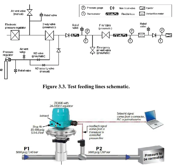
3.1.2 Feeding line
A schematic of the oxidizer feeding line is depicted in Figure 3.3.
Gaseous oxygen is supplied by a reservoir of 4 pressurized tanks connected to the motor feed line. The feeding pressure is then set by means of the TESCOM ER3000 electronically controlled pressure valve (see Figure 3.4), which regulates an electro-pneumatic valve in order to reduce the pressure to the desired set point. The control is performed on the basis of the pressure signal measured by a transducer located downstream the regulator. The presence of a chocked Venturi tube before the injector ensures that the set feeding pressure is directly proportional to the desired oxygen mass flow rate. The same device allows the evaluation of the latter parameter through gas temperature and pressure measurements upstream of the throat section.
CHAPTER 3. Experimental setup and firing test cases
26
An additional line is present for nitrogen purging into the chamber for the burn out and in case of an accident
Figure 3.3. Test feeding lines schematic.
Figure 3.4. Tescom ER3000 pressure controller scheme.
3.1.3 Signal measurements and data acquisition system
Several sensors are present for the measurement of significant quantities during experimental test, which are listed in the following.
Three capacitive pressure transducers and three thermocouples are located along the feeding line and at the section upstream of the oxidizer injector for the
![Figure 2.1. Molar fractions of the combustion products in rockets with different propellants [44]](https://thumb-eu.123doks.com/thumbv2/123dokorg/2758771.985/30.892.177.734.477.791/figure-molar-fractions-combustion-products-rockets-different-propellants.webp)
![Figure 2.3. Design of the test articles for C 3 HARME experimental campaign for characterization of UHTCMCs in propulsion application [59]](https://thumb-eu.123doks.com/thumbv2/123dokorg/2758771.985/34.892.170.748.603.1022/figure-articles-experimental-campaign-characterization-uhtcmcs-propulsion-application.webp)