Development and applications of an
inno-vative wearable system based on
time-of-flight technology for the measurement of
the human movement
Department of Computer, Control, and Management Engineering ‘Antonio Ruberti’
Research Doctorate in Automatic Control, Bioengineering and Operation Research (ABRO) – XXXI Cycle
Candidate:
Stefano BERTULETTI Student ID: 1700043
Thesis Supervisor: Prof. Ugo Della Croce
Co-Supervisor:
Prof. Andrea Cereatti
Thesis defended on 26/02/2019
in front of a Board of Examiners composed by: Prof. Giancarlo Bigi (chairman)
Prof. Giovanni Sparacino Prof. Giovanni Ulivi
Development and applications of an innovative wearable system based on time-of-flight technology for the measurement of the human movement
Ph.D. thesis. Sapienza – University of Rome
© 2018 Stefano BERTULETTI. All rights reserved
This thesis has been typeset by LATEX and the Sapthesis class.
Abstract
The analysis of the human movement is the subject of many research projects. Recently, thanks to the advancement in the development of high performance and low-power electronic components, wearable sensors have given rise to devices and techniques which allow an objective evaluation of different human movement quantities both inside and outside the laboratory setting (e.g. during activities of daily living).
The objectives of the research conducted and reported in this Ph.D. thesis regard the devise, development, validation and applications of an innovative wearable system, named SWING, for the human movement monitoring and analysis.
The SWING system is the result of a design aimed at providing a wireless system-on-board processing capabilities integrating a magneto-inertial measurement unit and a Bluetooth module (main board) and up to three infrared time-of-flight distance sensors (satellite boards). It was specifically devised to take advantage of the positive points of magneto-inertial measurement units, which are capable of measuring the human movement for a long period of time and also during daily life activities with a good level of accuracy, but also to overcome some of their limitations (e.g. drift, ferromagnetic interferences, etc.). Moreover, the SWING system allow the direct measurement of quantities, such as the inter-foot distance and the step width, that magneto-inertial measurement units can only obtained indirectly (high estimation errors).
The advantages of using the infrared time-of-flight technology over other tech-nologies, such as ultrasound and light intensity infrared which have been already investigated in the literature, are that the same or higher performance can be obtained with a simpler experimental setup (only one foot instrumented) and with a higher robustness to the changing of the experimental/environmental conditions (e.g. colour of the shoe, ambient light).
sensor performances was performed under experimental conditions resembling those encountered during gait.
Second, the SWING system was validated for the inter-foot distance estimation and step detection during walk on sixteen healthy subjects.
Third, the SWING system was tested and validated on a group of subjects characterised by highly abnormal gait patterns (e.g. low speed walks, foot dragging walks, use of walking aids) while performing a six-minute walking test.
Finally, by exploiting the Bluetooth low energy as an alternative solution for indoor-localisation and proximity sensing, a thorough characterisation of the received signal strength indicator and distance relationship under controlled conditions was provided.
The findings of this Ph.D. thesis lead to the conclusion that the SWING system and the proposed methods could be reliably applied to both normal and abnormal gaits obtaining a high level of accuracy while maintaining a very simple experimental setup (only one lower limb instrumented).
Indeed, the mean absolute errors obtained for the measurement of the inter-foot distance on healthy subjects were in the range of 9.3–12.4 mm.
The results of the validation of the SWING system, as step counter, showed an accuracy of 100 % on healthy and between 94.6 % and 98 % on pathological subjects (i.e. multiple sclerosis).
Lastly, the findings of the characterisation of the Bluetooth low energy technology for the inter-distance estimation showed an average percentage error of 25.7 % (0.4 m). Therefore, Bluetooth low energy can be a solution for indoor positioning applications, but cannot be used for proximity sensing applications which require very high accuracy (resolution down to 0.1 m).
Acknowledgments
I would like to express my sincere gratitude to my supervisor Prof. Ugo Della Croce and my co-supervisor Prof. Andrea Cereatti for all teachings, continuous support and constructive criticism during my Ph.D. experience.
I want also to thank Prof. Claudia Mazzà and people from the INSIGNEO Institute for all the support, kindness and friendship they showed me in Sheffield. I am also deeply grateful to my loving family for encouraging me to start the doctorate and for supporting me.
I want also to thank my lab mates and my friends in Bergamo, Sassari, Turin and Sheffield.
List of Publications and Patents
International Peer-Reviewed Journals
• S. Bertuletti, U. Della Croce, and A. Cereatti, “A wearable solution for accurate step detection based on the direct measurement of the inter-foot dis-tance”, Journal of Biomechanics, vol. 84, pp. 274 –277, 2019, issn: 0021-9290. doi: https://doi.org/10.1016/j.jbiomech.2018.12.039. [Online]. Available: http://www.sciencedirect.com/science/article/pii/S0021929018309382. • S. Bertuletti, A. Cereatti, D. Comotti, M. Caldara, and U. Della Croce,
“Static and dynamic accuracy of an innovative miniaturized wearable platform for short range distance measurements for human movement applications”,
Sensors, vol. 17, no. 7, 2017, issn: 1424–8220. doi: 10.3390/s17071492.
[Online]. Available: http://www.mdpi.com/1424-8220/17/7/1492.
Conference Proceedings published on International
Journals
• S. Bertuletti, F. Salis, A. Cereatti, L. Angelini, E. Buckley, K. Nair, C. Mazzà, and U. Della Croce, “Inter-leg distance measurement as a tool for accurate step counting in patients with multiple sclerosis”, IEEE Engineering
in Medicine and Biology Magazine (under review), 2019.
• S. Bertuletti, A. Cereatti, and U. Della Croce, “Development of a novel wearable system for real-time measurement of the inter-foot distance during gait”, Gait & Posture, vol. 57, pp. 6–7, 2017, SIAMOC, issn: 0966–6362. doi: 10.1016/j.gaitpost.2017.07.054. [Online]. Available: http://www.sciencedirect. com/science/article/pii/S0966636217307658.
• S. Bertuletti, A. Cereatti, M. Caldara, and U. Della Croce, “A proximity
tasks”, Gait & Posture, vol. 49, S15, 2016, SIAMOC, issn: 0966–6362. doi: 10.1016/j.gaitpost.2016.07.044. [Online]. Available: http://www.sciencedirect. com/science/article/pii/S0966636216301813.
• S. Bertuletti, A. Cereatti, M. Caldara, M. Galizzi, and U. Della Croce, “Indoor distance estimated from Bluetooth low energy signal strength: Comparison of regression models”, in Proceedings of IEEE Sensors Applications Symposium
(SAS), Apr. 2016, pp. 1–5. doi: 10.1109/SAS.2016.7479899.
National Conference Proceedings
• S. Bertuletti, U. Della Croce, and A. Cereatti, “A wearable prototype device for direct bilateral step detection by instrumenting a single foot”, in 19th
Proceedings of SIAMOC, 2018.
• S. Bertuletti, A. Cereatti, and U. Della Croce, “Inter-foot distance mea-surement in healthy adults during gait using a wearable prototype device: Validation on straight walking and turning for different distance sensor loca-tions”, in 19th Proceedings of SIAMOC, 2018.
• S. Bertuletti, A. Cereatti, and U. Della Croce, “A wearable system based on Time-of-Flight technology for direct derivation of step number and step width on healthy gait”, in Proceedings of GNB, 2018.
• S. Bertuletti, A. Cereatti, and U. Della Croce, “Detection of the turn switch during alpine skiing using a novel wearable system: A preliminary investiga-tion”, in 18th Proceedings of SIAMOC, 2017.
• S. Bertuletti, A. Cereatti, and U. Della Croce, “Measurement of the inter-foot distance using a Time-of-Flight proximity sensor: Preliminary evaluation during leg oscillation exercises”, in Proceedings of GNB, 2016.
• S. Bertuletti, A. Cereatti, M. Caldara, M. Galizzi, D. Comotti, and U. Della Croce, “Fall detection localization using Bluetooth low energy devices: A preliminary investigation”, in 16th Proceedings of SIAMOC, 2015.
International Conference Proceedings
• S. Bertuletti, A. Cereatti, and U. Della Croce, “A wearable system for step width measurement and step detection based on Time-of-Flight technology:
Preliminary validation on healthy subjects”, in Proceedings of 3-D Analysis
of Human Movement, 2018.
• S. Bertuletti, V. Camomilla, A. Cereatti, M. Caldara, M. Galizzi, and U. Della Croce, “Comparison of regression models for interdistance estimate between two BLE devices based on RSSI”, in Proceedings of 3-D Analysis of
Human Movement, 2016.
Patents
• A. Cereatti, S. Bertuletti, M. Caldara, and U. Della Croce, “Sistema per l’analisi dell’attività motoria di una persona e relativo metodo”, pat.
102017000003986, 2017, Italy (pending).
Contents
Abstract iii
Acknowledgments v
List of Publications and Patents vii
1 Introduction and Background 1
Objectives and Outline of the thesis . . . 1
Technologies for human movement monitoring and analysis . . . 2
I The SWING system
5
2 Hardware 9 2.1 Requirements . . . 9 2.2 Block scheme . . . 9 2.3 Configurations . . . 10 2.4 Design . . . 11 2.4.1 Main board . . . 112.4.2 Infrared time-of-flight satellite board . . . 20
3 Software 23 3.1 Embedded firmware . . . 23
3.1.1 Finite State Machine . . . 23
3.2 Graphical user interface . . . 26
4 Enclosures and Supports 29 4.1 Enclosures . . . 29
4.2 Supports . . . 30
5 Infrared time-of-flight sensor characterisation 33
5.1 Principle of functioning . . . 34
5.2 Analysed factors . . . 35
5.3 Experimental setup . . . 35
5.4 Experimental data acquisition . . . 35
5.5 Data analysis . . . 37
5.6 Results . . . 39
5.7 Accuracy evaluation . . . 41
II Applications
43
6 Gait analysis - Inter-foot distance measurement on healthy adults 45 6.1 Abstract . . . 456.2 Introduction . . . 45
6.3 Materials and Methods . . . 47
6.3.1 Hardware description . . . 47
6.3.2 Experimental setup and Data acquisition . . . 48
6.3.3 Data analysis . . . 49
6.4 Results . . . 50
6.5 Discussion . . . 52
6.6 Conclusion . . . 53
7 Gait analysis - Direct bilateral step detection on healthy adults 55 7.1 Abstract . . . 55
7.2 Introduction . . . 56
7.3 Methods . . . 56
7.3.1 System description - SWING2DS system . . . 56
7.3.2 Step detection method - IFOD step counter . . . 57
7.3.3 Experimental data collection . . . 58
7.3.4 Data processing and Accuracy assessment . . . 58
7.4 Results . . . 59
7.5 Discussion . . . 60
8 Clinical gait analysis - Direct bilateral step detection on multiple sclerosis patients 63 8.1 Abstract . . . 65
8.2 Introduction . . . 66
Contents
8.3 Materials and Methods . . . 67
8.3.1 System description – SWING system . . . 67
8.3.2 Participants . . . 67
8.3.3 Equipment and protocol . . . 69
8.3.4 Data analysis . . . 69
8.4 Results . . . 71
8.5 Discussion . . . 72
8.6 Conclusion . . . 73
9 Indoor positioning - Distance estimated from Bluetooth low energy signal strength 75 9.1 Abstract . . . 75
9.2 Introduction . . . 75
9.3 Materials and Methods . . . 76
9.3.1 Distance estimation based on RSSI measurement . . . 76
9.3.2 Hardware architecture . . . 77
9.3.3 Experimental setup . . . 79
9.3.4 Model parameters calibration . . . 79
9.3.5 Data analysis . . . 80 9.4 Results . . . 81 9.4.1 RSSI-distance relationship . . . 81 9.4.2 Regressive model . . . 83 9.5 Discussion . . . 83 9.6 Conclusion . . . 85
10 General results, Main contributions, and Future works 87
A Patient Information Sheet and Letter of Invitation, Informed Consent
Form and Data Collection Form 91
B Sports applications: Alpine skiing 101
Bibliography 103
List of Figures
2.1 Block scheme of the SWING system. . . 10
2.2 Microcontroller. . . 11
2.3 High speed external oscillator (8 MHz) and low speed external oscil-lator (32.768 kHz). . . 12
2.4 Accelerometer, gyroscope and magnetometer. . . 12
2.5 16 MB flash memory. . . 13
2.6 Bluetooth module with dedicated low-dropout regulator. . . 14
2.7 µUSB connector. . . . 15
2.8 Battery charger and fuel gauge module. . . 16
2.9 Buck regulator. . . 16
2.10 Satellite boards/infrared time-of-flight distance sensors connectors’. 17 2.11 Button with smart push-button on/off controller and LEDs. . . 17
2.12 Debug connector. . . 18
2.13 Printed circuit board 2D build up. . . 18
2.14 Top view of the SWING layout (units in millimeters). . . 19
2.15 Bottom view of the SWING layout (units in millimeters). . . 19
2.16 Top and bottom views of the fabricated and assembled SWING system. 20 2.17 VL6180X satellite board ready to be connected to the SWING system. 21 2.18 Circuit diagram of the custom infrared time-of-flight satellite board. 21 2.19 Top and bottom views of the custom infrared time-of-flight satellite board layout (units in millimiters). . . 22
2.20 Top view of the 3D rendering of the custom infrared time-of-flight satellite board. . . 22
3.1 Finite state machine of the SWING firmware. . . 24
3.2 Main window of the SWING graphical user interface. . . 26
3.3 Sensing units windows’ in the settings of the SWING graphical user interface. . . 27
3.4 Logger window in the settings of the SWING graphical user interface. 28
3.5 Configuration window in the settings of the SWING graphical user
interface. . . 28
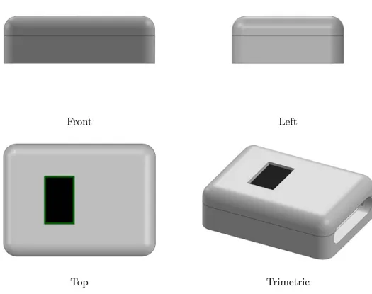
4.1 2D-views and 3D-view of the enclosure of the SWING system. . . . 29
4.2 2D-views and 3D-view of the enclosure of the STMicroelectronics
satellite “mini board”. . . 30
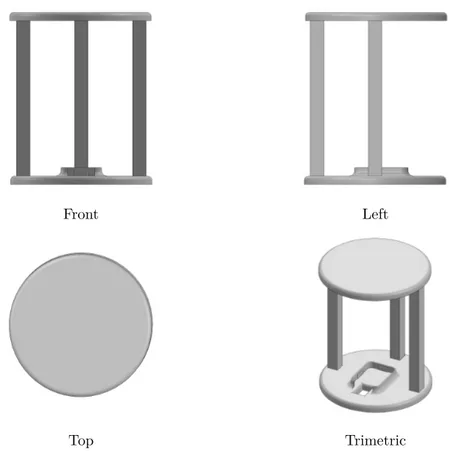
4.3 2D-views and 3D-view of the support specifically designed for the
SWING2DS system which incorporates in the middle the
magneto-inertial unit and two infrared time-of-flight distance sensors by the
sides of the support. . . 31
4.4 2D-views and 3D-view of the structure specifically designed for the
calibration of the infrared time-of-flight sensor . . . 32
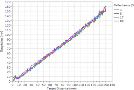
5.1 Typical ranging performance of the VL6180X sensor, provided by
STMicroelectronics (Geneva, Switzerland), for different target re-flectance (3 %, 5 %, 17 % and 88 %) by varying the range from 0 to
150 mm. . . 33
5.2 The infrared time-of-flight sensor provides the distance estimates
from the target reflecting surface by measuring the phase shift ϕ
between the emitted s(t) and the reflected r(t) signals. . . . 34
5.3 A wooden pendulum with the MIMU and the infrared time-of-flight
sensor attached to its distal end. The stationary target was positioned
in front of the pendulum. . . 36
5.4 The six colours of the rectangular cuboid targets used during the
static acquisitions (red, green, blue, yellow, white and black). . . 36
5.5 On the left, the top view of the experimental setup for angle of
incidence (AoI) equal to 0◦ (a), 30◦ (b) and 60◦ (c). The red dotted
line represents the infrared ray emitted by the infrared time-of-flight (ToF) sensor. d is the imposed distance using a ruler, while
dT oFk is the distance estimated by the infrared ToF sensor when
the gyroscope measured a positive/negative peak according to the
direction of the pendulum oscillation. dT oFi and dT oFf are the initial
and final estimated distances, respectively. On the right, for each AoI value, an example of the distance values measured by the infrared ToF sensor at d = 100 mm is reported. It should be noted that, in dynamic acquisitions, when the AoI differs from zero, the
sensor-target distance dT oF varies with time between dT oFi and dT oFf ((b)
and (c)). . . 38
List of Figures
5.6 An example of the readings, provided by the infrared time-of-flight
sensor and re-sampled at 100 Hz, is reported for an oscillation k with
an angle of incidence equal to 0◦ and d = 100 mm. The value of
dT oFk, obtained in correspondence of the angular velocity peak (red
square), is reported with a red circle. . . 39
5.7 The absolute values of the errors e computed by the infrared
time-of-flight sensor during all dynamic experiments are reported with a different colour for each angle of incidence (AoI) value. Furthermore, for each AoI value, a coloured line showed the trend of the absolute
errors with respect to the angular velocity. . . 41
6.1 Block diagram of the SWING system. . . 47
6.2 Top and bottom view of the 3D rendering of the SWING system. . 48
6.3 The SWING2DS system, target and markers placement on the feet:
(a) instrumented right foot; (b) left foot with target; (c) left foot
without target. . . 49
6.4 Markers positioning during the initial static calibration acquisition.
The marker positioned on the fifth metatarsophalangeal joint was
not considered in the data analysis of this study. . . 50
7.1 The SWING2DS system embedded on a custom 3D-printed rigid
support. . . 57
7.2 Experimental setup: (a) right foot with the SWING2DS system
(instrumented foot); (b) left foot (non-instrumented foot). . . 57
7.3 Synchronised time-series of raw SWING2DS data (REARDS and
FOREDS) and vertical component (z-axis) of right and left heel
markers (triangular markers indicate the heel strike and heel off) for
the stride of a subject during a rectilinear walk. . . 59
7.4 Potential missed step scenarios: (a) distance sensor positioned too
close to the ground and/or large foot clearance of the contralateral foot during swing; (b) abnormal foot external rotation during walking
and/or excessively large base of support. . . 61
8.1 Myelin damage and the nervous system. In multiple sclerosis, the
protective coating on nerve fibers (myelin) in the central nervous system becomes detached and eventually destroyed. This creates a lesion that may cause numbness, pain or tingling in parts of the body. 63
8.2 Global number of people with multiple sclerosis. . . 64
8.3 Block diagram of the SWING system. . . 68
8.4 A patient with multiple sclerosis wearing the SWING2DS system positioned above the right medial malleolus with the DS pointing to
the contralateral leg. . . 69
8.5 A schematic view of the six-minute walking test performed by a patient with multiple sclerosis. . . 69
8.6 Example of the application of the DiSC method on a participant for the DS200 and DS400 configuration. Missed NIN-steps are red highlighted. . . 71
8.7 Difference (Bland–Altman) plots for IN-step and NIN-step between DiSC method and reference system. Limits of agreement (±1.96 SD) are, respectively, 16, 13, 36, 36 steps. Bias are, respectively, -1.4, 0.5, -5.7, -0.4 steps. DS200 in green and DS400 in blue. . . 72
8.8 Mean errors (e) for DS200and DS400are reported for each participant based on the EDSS. . . 72
9.1 System connection overview. . . 77
9.2 Top and bottom view of the MIMU. . . 78
9.3 RSSI 10 s acquisition data example. . . 78
9.4 Typical free space radiation patterns of the W3008C radio antenna. 79 9.5 Experimental indoor scenario. . . 80
9.6 RSSI-distance relationship obtained for the MIMU1 working as receiver. 82 9.7 RSSI-angle relationship obtained for the MIMU1 working as receiver. 82 B.1 Experimental setup: right boot with the SWINGDS system. . . 101
B.2 Angular velocities (@100 Hz) and distance sensor (@50 Hz) signals acquired during a free ride. The detected ski turns switch are yellow highlighted. . . 102
List of Tables
2.1 Active sensors combinations for each SWING system configuration.
The • symbol denotes that the specific sensor is active. . . 10
3.1 List of the finite state machine state transitions of the SWING system. 25
5.1 Grand mean error with standard deviation (E ± SD), grand mean
absolute error (MAE) and grand mean absolute percentage error
(MAE%) of the distance for the six target colours. . . 39
5.2 Mean error with standard deviation (e ± sd), mean absolute error
(mae) and mean absolute percentage error (mae%) for an angle of
incidence equal to 0◦ during both static and dynamic acquisitions
using a white rectangular cuboid target. . . 40
5.3 Grand mean error and standard deviation (E ± SD), grand mean
absolute error (MAE) and grand mean absolute percentage error
(MAE%) of the distance for the five conditions (angle of incidence
(AoI) equal to 0◦, ±30◦ and ±60◦) using a white target. . . 40
6.1 Performance of REARDS and FOREDS for the measurement of the
inter-foot distance (IFD) during rectilinear sections of a loop for test
and retest session using the target on the contralateral foot. . . 51
6.2 Performance of REARDS and FOREDS for the measurement of the
inter-foot distance (IFD) during curvilinear sections of a loop for
test and retest session using the target on the contralateral foot. . . 51
6.3 Performance of REARDS and FOREDS for the measurement of the
inter-foot distance (IFD) during rectilinear sections of a loop for test
and retest session without using the target on the contralateral foot. 51
6.4 Performance of REARDS and FOREDS for the measurement of the
inter-foot distance (IFD) during curvilinear sections of a loop for test
and retest session without using the target on the contralateral foot. 52
7.1 Performance of the IFOD step counter for REARDS and FOREDS locations and test and retest sessions for the detection of the
instru-mented step (IN-step) during rectilinear walking portions. . . 59
7.2 Performance of the IFOD step counter for REARDS and FOREDS
locations and test and retest sessions for the detection of the
non-instrumented step (NIN-step) during rectilinear walking portions. . 60
7.3 Performance of the IFOD step counter for REARDS and FOREDS
locations and test and retest sessions for the detection of the
instru-mented step (IN-step) during curvilinear walking portions. . . 60
7.4 Performance of the IFOD step counter for REARDS and FOREDS
locations and test and retest sessions for the detection of the
non-instrumented step (NIN-step) during curvilinear walking portions. . 60
8.1 Specifications of the VL6180X time-of-flight distance sensor. . . 67
8.2 Demographic and clinical characteristics of patients. . . 68
8.3 The DiSC method performance across patients for each DS
configu-ration (DS200 vs DS400) and instrumented/non-instrumented leg. . . 71
9.1 Comparison between MIMU1 and MIMU2 RSSI recorded data. . . . 82
9.2 EXP10 model results, for MIMU1, MIMU2 and MIMU1,2, with two
calibration points. . . 83
9.3 POL model distance estimated errors, for validation data set, using
28, 16 and 12 calibration points. . . 84
9.4 EXPE model distance estimated errors, for validation data set, using
28, 16 and 12 calibration points. . . 84
9.5 POW model distance estimated errors, for validation data set, using
28, 16 and 12 calibration points. . . 84
Glossary
(M-)IMU (magneto-)inertial measurement unit. 55, 56 6MWT six-minute walking test. 76, 79, 83
AoI angle of incidence. 41–48
BLE Bluetooth low energy. 20, 85–88, 90, 91, 93, 95, 96, 101–103 BoS base of support. 56, 63, 71, 101
CT computer tablet. 87, 88
DiSC distance sensor step counter. 75, 76, 79–84, 102, 103
DS distance sensor. 55–60, 62, 63, 65–72, 75–77, 79, 81–84, 96, 103, 115, 116 E grand error. 45–47, 60, 80
e error. 46, 47, 60, 80, 82
E% grand mean percentage error. 75, 82, 83
EDSS expanded disability status scale. 75, 76, 78, 81–83 FSM finite state machine. 29–31
GPS global positioning system. 4, 85 GUI graphical user interface. 29, 30, 32–34 I2C inter-integrated circuit. 17, 23, 26 IC integrated circuit. 15, 21, 22, 25, 29
IDE integrated development environment. 29, 32 IFD inter-foot distance. 56, 57, 59–63, 101
IFOD inter-foot distance. 65, 66, 68–72, 102, 103
IMU inertial measurement unit. 3, 13, 65, 66, 71, 76, 83 IN-step instrumented step. 67–71, 79–82
IP intersection point. 59, 60
IR infrared radiation. 40, 48, 56, 57, 72 IR-LI light intensity infrared. 56, 62, 63, 96
MAE grand mean absolute error. 45–48, 60, 62, 80, 91, 95 mae mean absolute error. 46, 60, 80
MAE% grand mean absolute percentage error. 45–47, 60, 80–83, 91, 95
mae% mean absolute percentage error. 46, 60, 80
MIMU magneto-inertial measurement unit. 1, 3, 13, 39, 42, 55, 59, 86–93, 96,
101, 115, 116
MS multiple sclerosis. 73–78, 83, 84
NIN-step non-instrumented step. 67–71, 79–82 ODR output data rate. 48, 56
PCB printed circuit board. 17, 20, 24
RSSI received signal strength indicator. 2, 4, 85–95, 102, 103 RTC real-time clock. 17, 18, 30, 32
SD grand standard deviation. 45–47, 60 sd standard deviation. 46, 60
SP system stereo-photogrammetric system. 57–60, 68 SPI serial peripheral interface. 17–19, 21
Glossary
SW step width. 3, 41, 48, 56, 63, 101
ToF time-of-flight. 1, 13, 15, 19, 22, 23, 25–28, 30, 32, 33, 36–48, 101, 102 UART universal asynchronous receiver-transmitter. 18, 20
US ultrasound. 56, 62, 63, 96
USART universal synchronous and asynchronous receiver-transmitter. 17, 20 USB universal serial bus. 18, 21, 25, 31
1
Introduction and Background
Objectives and Outline of the thesis
The objectives of the research conducted and reported in this Ph.D. thesis regard the devise, development, validation and applications of an innovative wearable system for the human movement monitoring and analysis. This system must allow the measurement of accelerations, angular velocities and local magnetic field, but also it has to be able to detect the presence of nearby objects without any physical contact and to provide position estimates in an indoor environment due to the fact that 60 % of daily time is spent indoor. Therefore, the innovative system will have to integrate in the same system a magneto-inertial measurement unit (MIMU), at least one infrared time-of-flight (ToF) distance sensor and a Bluetooth module.
The thesis is organised as follows:
Introduction and Background reports the objectives of this thesis and its
structure, and introduces the topic through the presentation of the technologies used for the analysis and monitoring of the human movement.
Part I - The SWING system presents the development of an innovative
wearable system, named SWING, “from the idea to the product”. Starting from the requirements that the system must comply and the selection of most suitable and performing electronic components. The circuit diagram and the printed circuit board were designed and described in Chapter 2. A description of the implemented firmware and the developed graphical user interface was provided in Chapter 3. As the system has to be worn, the enclosures of the SWING system and the infrared ToF distance sensors were designed and printed using a 3D printer. Furthermore, to make the SWING system easy to use and wear and to facilitate its calibration,
a support for the SWING2DS and for the calibration of the infrared ToF distance
sensors were also designed and printed (Chapter 4). Finally, in Chapter 5, the
characterisation of the infrared ToF distance sensor in both static and dynamic conditions resembling those encountered when analysing human movement was provided.
Part II - Applications presents the applications in which the SWING system
was tested and validated. The applications were grouped by two categories: i) gait analysis/clinical gait analysis (Chapter 6, 7 and 8): the SWING system was validated against a stereophotogrammetric system or video recordings to provide information about the inter-foot distance while walking on healthy subjects and step detection on both healthy and pathological subjects (multiple sclerosis patients);
ii) indoor positioning (Chapter 9): the Bluetooth low energy module, which could
be embedded in the SWING system, was used to provide distance information based on the received signal strength indicator (RSSI) reads from another SWING system (beacon node).
General results, Main contributions, and Future works summarises the
achievements of the research performed during the Ph.D. program and provides an outlook for future research.
Technologies for human movement monitoring and
analysis
The monitoring and analysis of the human movement aim at providing objective quantities of the musculo-skeletal system (e.g. kinetic, kinematic and muscles forces) during the execution of a motor task.
Traditionally, the measurement of these quantities is conducted under controlled conditions in laboratories by means of technologies such as cameras (e.g. motion capture systems [16]), force plates [17] and instrumented walkways [18]. These technologies provides measurements that are very accurate, highly repeatable and reproducible [19] and, since these systems are directly connected to the power source, do not have power consumption restrictions. However, their use is restricted to laboratory settings thus not allowing the assessment of the human motion during daily-life activities. Furthermore, they are costly and the measurement process must be carried out by specialised personnel.
Over the past decades, thanks to the advancement in the development of minia-turised, less power consuming and more performing electronic components, wearable technologies have gained popularity in the analysis and monitoring of the human movement [20]. Wearable technologies make it possible to analyse, monitor and
capture a wide range of information of the human movement also outside the laboratory and during activities of daily living [21]. They can provide a wide range of measurements of the human motion and related quantities: joint kinematics [22], forces and moments [23], biosignals [24] and locating, tracking and positioning [25]. However, some factors such as performance, limitations of their use, noise, interference of external factors present in the environment and power consumption restrictions due to the limited battery duration, must be taken into account.
Among wearable technologies aimed at measuring the human movement inertial measurement unit (IMU) is the most popular. IMU consist of a tri-axial accelerom-eter and a tri-axial gyroscope capable of measuring linear accelerations and angular velocities in the 3D components, respectively. An assembly of an IMU and a tri-axial magnetometer, which measures the local magnetic field in the 3D components, is generally referred to as a MIMU. MIMUs are tiny, light-weight, can provide both real-time data streaming and data logging depending on the application and can be connected each other wirelessly to create a synchronised network. Due to their characteristics and depending on the parameter of interest, MIMUs can be easily attached to one or more body segments (e.g. head, wrist, pelvis, shank, ankle, foot, etc.) and can be used in a large variety of applications such as clinical and health monitoring [26], sports science [27] and entertainment [28].
Although they are increasingly used, a typical problem that affect the computation and that must be taken into account refers to the single and double integration of linear accelerations and angular velocities which are both affected by noise (drift). Another problem is related to the gravity that has to be decomposed in the three components according to the IMU orientation (local reference system) and then removed before the integration. Mostly in indoor environments, the biggest limitation referred to the magnetometer is related to additional magnetic fields which can cause interferences. Interferences can be caused by ferromagnetic material or equipment nearby the magnetometer (“soft iron” and “hard iron” interferences).
To reduce/eliminate the above-mentioned problems and limitations and the need to measure new quantities which cannot be measured by MIMU such as spatial information (e.g. step width (SW) during walking, etc.) and position (e.g. human navigation) have led to the integration of MIMU with other technologies.
Video cameras and distance sensors are different technologies capable of providing spatial information. In the last few years, the technology advance of electronic devices allowed to develop always smaller and smaller video cameras that are specifically designed to be worn on the human body, for example on the chest or that can be embedded in clothes or accessories such as eyeglasses [29]. Video cameras provide a very large quantity of data. However, their use for monitoring
and to analyse the human motion is limited to the ability to develop algorithms capable of extrapolating information from the analysis of image frames which require high computational capacity and intelligence [30]. Proximity sensors are electronic devices able to detect the presence of nearby objects without any physical contact. They can be implemented based on different technologies: ultrasound, photoelectronic, inductive, capacitive and magnetic. Proximity sensors can provide several information based on their location on the human body. For instance, they can be used for obstacle avoidance [31] or in addition, when positioned on the feet, they can measure the relative foot positions [32] and foot clearance [33].
The most common technology for the estimation of the position is represented by the global positioning system (GPS). GPS is a satellite-based radionavigation system owned by the United States of America [34]. GPS provides geolocation of a GPS receiver where there is an unobstructed line of sight to four or more GPS satellites. Nowadays, since GPS is already embedded in the common wearable technologies (e.g. smartphone, smartwatch, etc.), it is very widespread and used for several applications (e.g. navigation, sports, etc.). Main limitations of GPS are due to the low position accuracy (about 5 m), low sampling rate (about 1 Hz) and obstacles such as buildings block that can affect the power of the GPS signal and therefore its accuracy. As a result, GPS cannot be used in indoor environments thus other technologies solutions must be undertaken.
An alternative solution can be the use of barometric pressure sensors which are devices that measure the atmospheric pressure. Generally, barometric pressure sensors consist of a capacitve or piezoelectric sensing element which detects absolute pressure by measuring the changes in the capacitance or thickness of the sensing element depending on the atmospheric pressure. They are used especially for indoor positioning to calculate altitude or to determine floor level in a building (z-axis) [35]. However, they cannot provide information about the position in the x-y plane. A further and promising alternative solution for the position estimation could be provided by Bluetooth. Bluetooth is a short-range wireless communication technology that allows devices to transmit data wirelessly over a short distance [36]. Even if Bluetooth is mainly used for data transmission, it can be also used for localization in an indoor environment. Upon comparing the received signal values from Bluetooth devices, positioned in known locations of the environment (beacons), is possible to get the first, rough position estimate through the RSSI.
RSSI represents a value of the power of a received radio signal. The longer the distance is, the lower the RSSI signal is. By integrating the RSSI signal from at least three different beacons is possible to determine the position by implementing trilateration algorithms [37].
Part I
The SWING system
This part will illustrate the design, development, realisation and characterisation of a novel wearable system, named SWING, aimed at monitoring and analyse the human movement.
The novel idea of the SWING system, with respect to those available on the market, is related to the integration of magneto-inertial data, Bluetooth data and distance data into a single system. At present time, MIMUs (comprising also Bluetooth) and distance sensors are sold singly, thus the quantities provided by these three technologies are not yet integrated. In the research field only few works presented the integration of MIMUs and distance sensors. Trojaniello et al. [38] used a system integrating an IMU and an infrared distance sensor. In this work, the system was used to measure the inter-foot distance during static and dynamic conditions (leg oscillation and walking) on a single healthy subject while wearing the system on a foot and a white target on the contralateral one. Weenk et al. [32] proposed a system which integrates an inertial sensor and an ultrasound transducer on each foot for the measurement of the relative foot position (e.g. step length, stride width) on three healthy adults. Duong et al. [39] presented a methodology to improve the accuracy of foot pose estimation by attaching two infrared ToF distance sensors pointing the ground on a shoe in addition to an IMU.
The main advantage of the development of a new system from scratch (white box) is that the design and implementation of the hardware and the software (e.g. algo-rithms) are defined and known to the developer. Not necessarily, this information are known to the end user of a commercial devise (black box). Furthermore, this integration aimed at i) measuring quantities that cannot be measured by MIMUs and Bluetooth alone; ii) directly measuring quantities (i.e. distances) instead of obtaining them indirectly by double integrating accelerations and iii) improving the accuracy of algorithms based only on magneto-inertial data, Bluetooth data or distance data.
2
Hardware
2.1 Requirements
The SWING system was designed to comply the following specific requirements:
i) it has to be tiny and light-weight in order to be easily worn by a person; ii) it
has to integrate an accelerometer, a gyroscope and a magnetometer; iii) it has to integrate up to three infrared ToF distance sensors; iv) the onboard microcontroller has to offer enough power and processing capabilities to host intensive algorithms (e.g. online Kalman Filter) and user-define application code; v) it has to provide real-time data streaming (i.e. integrating a Bluetooth module) and data logging (i.e. integrating a flash memory); vi) it has to be powered by a rechargeable battery
and finally vii) it has to provide at least 8 h of battery life.
2.2 Block scheme
An overview of the SWING system is reported in Figure 2.1. It is composed of two different types of units: the main board and the satellite board. The main board integrates all the components aimed at processing, sensing, storing data and connecting to external devices and it integrates all integrated circuits (ICs) dedicated to the power management and I/O, while the satellite board integrates the infrared ToF distance sensor. Up to three satellite boards can be simultaneously connected to the main board. A further description of these two boards is provided in section Design.
The infrared ToF distance sensor was integrated in a different board in order to make the SWING system more versatile to the customer needs and to be used in a wide range of applications. This hardware configuration enables the customer to position each satellite board in a different place with respect to the other satellite board and to the main board.
Main Board
Figure 2.1 – Block scheme of the SWING system.
2.3 Configurations
The SWING system has been designed to be used in four different hardware configurations depending on the requirements of the application in which it has to be used. In Table 2.1, for each configuration, are reported all the combinations of active sensors which are automatically detected by the system by plugging in/out the satellite boards.
Table 2.1 – Active sensors combinations for each SWING system configuration. The • symbol denotes that the specific sensor is active.
Configuration Active sensors
MIMU Sat. Board #1 Sat. Board #2 Sat. Board #3
SWING • SWINGDS • • • • • • SWING2DS • • • • • • • • • SWING3DS • • • • 10
2.4 Design
2.4 Design
The circuit diagram of the SWING system was designed with the Autodesk EAGLE software. Autodesk EAGLE is a freeware electronic design automation software enabling printed circuit board (PCB) designers to seamlessly connect schematic diagrams, component placement, PCB routing and comprehensive library content.
2.4.1 Main board
Schematics Processing
The core processing unit of the SWING system is the STM32L433CC (Figure 2.2) [40]. The STM32L433CC is an ultra-low-power microcontroller based on the
high-performance ARM® Cortex®-M4 32-bit core operating at a frequency of up
to 80 MHz. The Cortex-M4 core features a floating point unit single precision which supports all ARM single-precision data processing instructions and data types. It also implements a full set of digital signal processor instructions and a memory protection unit which enhances application security. The STM32L433CC microcontroller embeds high-speed memories (256 kB of flash memory and 64 kB of static random access memory), a low-power real-time clock (RTC) and an extensive range of enhanced I/Os and peripherals. It also features standard and advanced communication interfaces, among which: three inter-integrated circuits (I2Cs), three serial peripheral interfaces (SPIs), three universal synchronous and asynchronous
Special Footprint for mounting BT 3.0 or 4.1 modules Pin name 3.0 / 4.1
If BT 4.1 mounted --> Mount R21 If BT 3.0 mounted --> Not mount R21
8 MHz Crystal SWD Debugger g re e n b lu e o ra n g e R12[k]=1000/Icharge[mA] Icharge=50mA --> R12=20k Icharge=70mA --> R12=14.3k 32.768 kHz Crystal 1 -> GND 2 -> I2C_SDA 3 -> I2C_SCL 4 -> INT 5 -> GPIO_0 6 -> VDD ERNI (214013) connectors for up to 3 VL6180X proximity sensors
GND VBAT 1u 100n V D D STM6600 E V Q Q 2 1 M 4.7n MAX17048X+ V D D TPS62740 10u 10u V C C 1 0 0 1 0 1 0 1u 1u 100n 1u 100n 4 7 k GND GND 4.7u GND GND GND GND 1u GND 1u GND 1u GND GND GND GND GND GND GND GND 5 1 0 k LSM303D V C C 10V 220n G R M 0 3 3 R 6 1 A 2 2 4 M E 9 0 D V C C GND GND GND 4.7u 1u 1u SPBT2632C2A/SPBTLE-RF GND VCC 100n GND 100n GND VC C GND G N D MCP73831T-2ACI_OT GND 1 6 k GND GND 4.7u GND V C C S25FL127SABMFI101 TPD2E001DRLR GND GND 1 M 214013 214013 214013 STM32L433CCT6 V D D VDD VDD V D D ABS09-32.768KHZ-1-T 15p 15p GND TPS70918QDBVRQ1 GND 4.7u GND 1 0 0 k GND G N D G N D G N D VCC VCC VCC VDD GND NC7SZ32M5X VDD 2.2uH PBRC8.00HR50X000 GND 4 7 k V D D 100n GND V C C 4.7u GND MCP73831T-2ACI_OT GND 1 6 k GND GND 4.7u MAX17048X+ GND GND C1 C2 /VCC P7 /PB P6 /SR P2 V C C P 1 E N P 9 /RST P10 PSHOLD P4 /INT P11 /PBOUT P8 VREF P3 C S R D P 5 G N D P 1 2 U2 S W 1 L E D 2 L E D 1 L E D 3 R 5 C13 VDD A3 CELL A2 CTG A1 GND A4 QSTRT B3 SCL B2 SDA B1 /ALRT B4 U5 VIN P1 EN P12 VSEL1 P11 VSEL2 P10 VSEL3 P9 VSEL4 P8 GND P3*6 LOADCTRL P6 P4 PG P7 VOUT P5 SW P2 U7 C16 C18 R 4 R 2 R 3 C3 C4 C5 C6 C7 P1 P1 P2 P2 P3 P3 P4 P4 P5 P5 G 1 G 1 G 2 G 2 G 3 G 3 G 4 G 4 G 5 G 5 G 6 G 6 USB1 R 9 C15 C11 C12 C10 R 6 VDD_IO P1 SETC P2 SETP P3 SCL P4 GND1 P5 S D A P 6 S D O P 7 C S P 8 INT2 P9 RES P10 INT1 P11 GND2 P12 GND3 P13 V D D P 1 4 C 1 P 1 5 G N D 4 P 1 6 U8 C19 C20 C21 C22 GPIO1/SPI_MISO P1/8 GPIO2/SPI_MOSI P2/9 GPIO3/SPI_CS P3/10 GPIO4/RES P4/11 GPIO5/NC P5/NC GPIO6/NC P6/NC GND/NC P7/NC BOOT/NCVIN/NC P8/NC P9/NC RES/NC P10/NC CTS/EXT_LPO P11/1 RTS/GPIO P12/2 RX/AN_TEST P13/3 TX/SPI_IRQ P14/4 N C /G N D N C /6 NC/SPI_CLK NC/7 NC/VIN NC/5 U11 SDO P1 SDX P2 SCX P3 INT1 P4 V D D IO P 5 G N D 1 P 6 G N D 2 P 7 VDD P8 INT2 P9 OCS P10 NC P11 C S P 1 2 S C L P 1 3 S D A P 1 4 U9 C24 C23 U4 STAT 1 VSS 2 VBAT 3 VDD 4 PROG 5 R 8 C14 U12 CS# 1 SO/IO1 2 WP#/IO2 3 GND 4 VCC 8 HOLD#_/_IO3_OR_IO3_/_RESET# 7 CLK 6 SI/IO0 5 U3 VCC 1 NC 2 IO1 3 GND 4 IO2 5 R 7 J_PROX1 1 1 3 3 5 5 2 2 4 4 6 6 NC 7*4 J_PROX2 1 1 3 3 5 5 2 2 4 4 6 6 NC 7*4 J_PROX3 1 1 3 3 5 5 2 2 4 4 6 6 NC 7*4 U1 VBAT 1 PC13 2 PC14-OSC32_IN 3 PC15-OSC32_OUT 4 PH0-OSC_IN 5 PH1-OSC_OUT 6 NRST 7 VSSA/VREF-8 VDDA/VREF+ 9 PA0 10 PA1 11 PA2 12 P A 3 1 3 P A 4 1 4 P A 5 1 5 P A 6 1 6 P A 7 1 7 P B 0 1 8 P B 1 1 9 P B 2 2 0 P B 1 0 2 1 P B 1 1 2 2 V S S (1 ) 2 3 V D D (1 ) 2 4 VDDUSB 36 VSS(2) 35 PA13 34 PA12 33 PA11 32 PA10 31 PA9 30 PA8 29 PB15 28 PB14 27 PB13 26 PB12 25 V D D (2 ) 4 8 V S S (3 ) 4 7 P B 9 4 6 P B 8 4 5 P H 3 /B O O T 0 4 4 P B 7 4 3 P B 6 4 2 P B 5 4 1 P B 4 4 0 P B 3 3 9 P A 1 5 3 8 P A 1 4 3 7 Y1 1 1 2 2 C8 C9 U10 IN 1 GND 2 EN 3 NC 4 OUT 5 C25 R 1 0 P$1 P$1 P$2 P$2 P$3 P$3 P$4 P$4 P$5 P$5 P$6 P$6 P$7 P$7 P$8 P$8 P$9 P$9 P$10 P$10 CN1 U6 A 1 B 2 GND 3 Y 4 VCC 5 L1 X1 1 1 2 2 3 3 P$1 P$2 CN2 R 1 C17 C26 U13 STAT 1 VSS 2 VBAT 3 VDD 4 PROG 5 R 1 1 C27 VDD A3 CELL A2 CTG A1 GND A4 QSTRT B3 SCL B2 SDA B1 /ALRT B4 U14 G N D GND G N D GND GND GND BT33_RXD BT33_RXD S W C L K SWCLK SWDIO SWDIO S P I1 _ M IS O SPI1_MISO SPI1_MISO SPI1_MISO S P I1 _ M IS O S P I1 _ M O S I S P I1 _ M O S I SPI1_MOSI SPI1_MOSI S P I1 _ M O S I NRST NRST V_USB V_USB V_USB HSE_OSC_IN H S E _ O S C _ IN HSE_OSC_OUT H S E _ O S C _ O U T V R E G _ E N VREG_EN PS_HOLD PS_HOLD PS_INT P S _ IN T B A T T _ L O W B A T T _ L O W PB_OUT P B _ O U T P B U T T O N P B U T T O N P_GOOD VCC VCC_EN V C C _ E N VBATT VBATT V B A T T VBATT VBATT VBATT VBATT VBATT VBATT STAT STAT STAT VBT33 VBT33 E N _ B T 3 3 E N _ B T 3 3 SPI1_CLK S P I1 _ C L K SPI1_CLK SPI1_CLK S P I1 _ C L K BT33_TXD BT33_TXD ALRT_GAUGE A L R T _ G A U G E ALRT_GAUGE C S _ A M C S _ A M CS_FLASH CS_FLASH L E D 1 L E D 1 L E D 2 L E D 2 BLE_CS B L E _ C S V_USB_SENSE V_USB_SENSE V_USB_SENSE BT_GPIO/BLE_RES C S _ A G C S _ A G INT_AG IN T _ A G GPIO_PROX_1 GPIO_PROX_1 INT_PROX_1 INT_PROX_1 INT_PROX_2 IN T _ P R O X _ 2 INT_PROX_3 INT_PROX_3 GPIO_PROX_2 G P IO _ P R O X _ 2 GPIO_PROX_3 GPIO_PROX_3 L S E _ O S C _ IN LSE_OSC_IN L S E _ O S C _ O U T LSE_OSC_OUT INT_AM IN T _ A M USB_DP USB_DP USB_DM USB_DM I2 C 2 _ S C L I2C2_SCL
I2C2_SCL I2C2_SCL I2C2_SCL
I2C2_SCL I2C2_SDA I2C2_SDA I2C2_SDA I2C2_SDA I2 C 2 _ S D A I2C2_SDA BT33_TXD: USART1 RX (PA10) BT33_RXD: USART1 TX (PA9) SWING_v8.0 not saved! 1/1 Sheet: A B C D 1 2 3 4 5 6 A B C D 1 2 3 4 5 6 SWING_v8.0 not saved! 1/1 Sheet: A B C D 1 2 3 4 5 6 A B C D 1 2 3 4 5 6 SWING_v8.0 not saved! 1/1 Sheet: A B C D 1 2 3 4 5 6 A B C D 1 2 3 4 5 6 SWING_v8.0 not saved! 1/1 Sheet: A B C D 1 2 3 4 5 6 A B C D 1 2 3 4 5 6 SWING_v8.0 not saved! 1/1 Sheet: A B C D 1 2 3 4 5 6 A B C D 1 2 3 4 5 6 SWING_v8.0 not saved! 1/1 Sheet: A B C D 1 2 3 4 5 6 A B C D 1 2 3 4 5 6 M ic ro U S B A B C A B C 1 2 3 4 5 6 A B C A B C 1 2 3 4 5 6 Figure 2.2 – Microcontroller. 11
Chapter 2 Hardware
transmitters (USARTs), one low-power universal asynchronous receiver-transmitter (UART) and a universal serial bus (USB) full-speed device crystal less. A comprehensive set of power-saving modes, such as stop mode, standby mode and shutdown mode, allows the design of low-power applications.
Instead of using the internal oscillator, a more stable clock source has been obtained by connecting an external crystal oscillator. In particular, the 8 MHz SMD crystal oscillator with a frequency tolerance of ±0.5 % was used [41] (Figure 2.3).
Special Footprint for mounting BT 3.0 or 4.1 modules Pin name 3.0 / 4.1
If BT 4.1 mounted --> Mount R21 If BT 3.0 mounted --> Not mount R21
8 MHz Crystal SWD Debugger g re e n b lu e o ra n g e R12[k]=1000/Icharge[mA] Icharge=50mA --> R12=20k Icharge=70mA --> R12=14.3k 32.768 kHz Crystal 1 -> GND 2 -> I2C_SDA 3 -> I2C_SCL 4 -> INT 5 -> GPIO_0 6 -> VDD ERNI (214013) connectors for up to 3 VL6180X proximity sensors
GND VBAT 1u 100n V D D STM6600 E V Q Q 2 1 M 4.7n MAX17048X+ V D D TPS62740 10u 10u V C C 1 0 0 1 0 1 0 1u 1u 100n 1u 100n 4 7 k GND GND 4.7u GND GND GND GND 1u GND 1u GND 1u GND GND GND GND GND GND GND GND 5 1 0 k LSM303D V C C 10V 220n G R M 0 3 3 R 6 1 A 2 2 4 M E 9 0 D V C C GND GND GND 4.7u 1u 1u SPBT2632C2A/SPBTLE-RF GND VCC 100n GND 100n GND VC C GND G N D MCP73831T-2ACI_OT GND 1 6 k GND GND 4.7u GND V C C S25FL127SABMFI101 TPD2E001DRLR GND GND 1 M 214013 214013 214013 STM32L433CCT6 V D D VDD VDD V D D ABS09-32.768KHZ-1-T 15p 15p GND TPS70918QDBVRQ1 GND 4.7u GND 1 0 0 k GND G N D G N D G N D VCC VCC VCC VDD GND NC7SZ32M5X VDD 2.2uH PBRC8.00HR50X000 GND 4 7 k V D D 100n GND V C C 4.7u GND MCP73831T-2ACI_OT GND 1 6 k GND GND 4.7u MAX17048X+ GND GND C1 C2 /VCC P7 /PB P6 /SR P2 V C C P 1 E N P 9 /RST P10 PSHOLD P4 /INT P11 /PBOUT P8 VREF P3 C S R D P 5 G N D P 1 2 U2 S W 1 L E D 2 L E D 1 L E D 3 R 5 C13 VDD A3 CELL A2 CTG A1 GND A4 QSTRT B3 SCL B2 SDA B1 /ALRT B4 U5 VIN P1 EN P12 VSEL1 P11 VSEL2 P10 VSEL3 P9 VSEL4 P8 GND P3*6 LOADCTRL P6 P4 PG P7 VOUT P5 SW P2 U7 C16 C18 R 4 R 2 R 3 C3 C4 C5 C6 C7 P1 P1 P2 P2 P3 P3 P4 P4 P5 P5 G 1 G 1 G 2 G 2 G 3 G 3 G 4 G 4 G 5 G 5 G 6 G 6 USB1 R 9 C15 C11 C12 C10 R 6 VDD_IO P1 SETC P2 SETP P3 SCL P4 GND1 P5 S D A P 6 S D O P 7 C S P 8 INT2 P9 RES P10 INT1 P11 GND2 P12 GND3 P13 V D D P 1 4 C 1 P 1 5 G N D 4 P 1 6 U8 C19 C20 C21 C22 GPIO1/SPI_MISO P1/8 GPIO2/SPI_MOSI P2/9 GPIO3/SPI_CS P3/10 GPIO4/RES P4/11 GPIO5/NC P5/NC GPIO6/NC P6/NC GND/NC P7/NC BOOT/NCVIN/NC P8/NC P9/NC RES/NC P10/NC CTS/EXT_LPO P11/1 RTS/GPIO P12/2 RX/AN_TEST P13/3 TX/SPI_IRQ P14/4 N C /G N D N C /6 NC/SPI_CLK NC/7 NC/VIN NC/5 U11 SDO P1 SDX P2 SCX P3 INT1 P4 V D D IO P 5 G N D 1 P 6 G N D 2 P 7 VDD P8 INT2 P9 OCS P10 NC P11 C S P 1 2 S C L P 1 3 S D A P 1 4 U9 C24 C23 U4 STAT 1 VSS 2 VBAT 3 VDD 4 PROG 5 R 8 C14 U12 CS# 1 SO/IO1 2 WP#/IO2 3 GND 4 VCC 8 HOLD#_/_IO3_OR_IO3_/_RESET# 7 CLK 6 SI/IO0 5 U3 VCC 1 NC 2 IO1 3 GND 4 IO2 5 R 7 J_PROX1 1 1 3 3 5 5 2 2 4 4 6 6 NC 7*4 J_PROX2 1 1 3 3 5 5 2 2 4 4 6 6 NC 7*4 J_PROX3 1 1 3 3 5 5 2 2 4 4 6 6 NC 7*4 U1 VBAT 1 PC13 2 PC14-OSC32_IN 3 PC15-OSC32_OUT 4 PH0-OSC_IN 5 PH1-OSC_OUT 6 NRST 7 VSSA/VREF-8 VDDA/VREF+ 9 PA0 10 PA1 11 PA2 12 P A 3 1 3 P A 4 1 4 P A 5 1 5 P A 6 1 6 P A 7 1 7 P B 0 1 8 P B 1 1 9 P B 2 2 0 P B 1 0 2 1 P B 1 1 2 2 V S S (1 ) 2 3 V D D (1 ) 2 4 VDDUSB 36 VSS(2) 35 PA13 34 PA12 33 PA11 32 PA10 31 PA9 30 PA8 29 PB15 28 PB14 27 PB13 26 PB12 25 V D D (2 ) 4 8 V S S (3 ) 4 7 P B 9 4 6 P B 8 4 5 P H 3 /B O O T 0 4 4 P B 7 4 3 P B 6 4 2 P B 5 4 1 P B 4 4 0 P B 3 3 9 P A 1 5 3 8 P A 1 4 3 7 Y1 1 1 2 2 C8 C9 U10 IN 1 GND 2 EN 3 NC 4 OUT 5 C25 R 1 0 P$1 P$1 P$2 P$2 P$3 P$3 P$4 P$4 P$5 P$5 P$6 P$6 P$7 P$7 P$8 P$8 P$9 P$9 P$10 P$10 CN1 U6 A 1 B 2 GND 3 Y 4 VCC 5 L1 X1 1 1 2 2 3 3 P$1 P$2 CN2 R 1 C17 C26 U13 STAT 1 VSS 2 VBAT 3 VDD 4 PROG 5 R 1 1 C27 VDD A3 CELL A2 CTG A1 GND A4 QSTRT B3 SCL B2 SDA B1 /ALRT B4 U14 G N D GND G N D GND GND GND BT33_RXD BT33_RXD S W C L K SWCLK SWDIO SWDIO S P I1 _ M IS O SPI1_MISO SPI1_MISO SPI1_MISO S P I1 _ M IS O S P I1 _ M O S I S P I1 _ M O S I SPI1_MOSI SPI1_MOSI S P I1 _ M O S I NRST NRST V_USB V_USB V_USB HSE_OSC_IN H S E _ O S C _ IN HSE_OSC_OUT H S E _ O S C _ O U T V R E G _ E N VREG_EN PS_HOLD PS_HOLD PS_INT P S _ IN T B A T T _ L O W B A T T _ L O W PB_OUT P B _ O U T P B U T T O N P B U T T O N P_GOOD VCC VCC_EN V C C _ E N VBATT VBATT V B A T T VBATT VBATT VBATT VBATT VBATT VBATT STAT STAT STAT VBT33 VBT33 E N _ B T 3 3 E N _ B T 3 3 SPI1_CLK S P I1 _ C L K SPI1_CLK SPI1_CLK S P I1 _ C L K BT33_TXD BT33_TXD ALRT_GAUGE A L R T _ G A U G E ALRT_GAUGE C S _ A M C S _ A M CS_FLASH CS_FLASH L E D 1 L E D 1 L E D 2 L E D 2 BLE_CS B L E _ C S V_USB_SENSE V_USB_SENSE V_USB_SENSE BT_GPIO/BLE_RES C S _ A G C S _ A G INT_AG IN T _ A G GPIO_PROX_1 GPIO_PROX_1 INT_PROX_1 INT_PROX_1 INT_PROX_2 IN T _ P R O X _ 2 INT_PROX_3 INT_PROX_3 GPIO_PROX_2 G P IO _ P R O X _ 2 GPIO_PROX_3 GPIO_PROX_3 L S E _ O S C _ IN LSE_OSC_IN L S E _ O S C _ O U T LSE_OSC_OUT INT_AM IN T _ A M USB_DP USB_DP USB_DM USB_DM I2 C 2 _ S C L I2C2_SCL
I2C2_SCL I2C2_SCL I2C2_SCL
I2C2_SCL I2C2_SDA I2C2_SDA I2C2_SDA I2C2_SDA I2 C 2 _ S D A I2C2_SDA BT33_TXD: USART1 RX (PA10) BT33_RXD: USART1 TX (PA9) SWING_v8.0 not saved! 1/1 Sheet: A B C D 1 2 3 4 5 6 A B C D 1 2 3 4 5 6 SWING_v8.0 not saved! 1/1 Sheet: A B C D 1 2 3 4 5 6 A B C D 1 2 3 4 5 6 SWING_v8.0 not saved! 1/1 Sheet: A B C D 1 2 3 4 5 6 A B C D 1 2 3 4 5 6 SWING_v8.0 not saved! 1/1 Sheet: A B C D 1 2 3 4 5 6 A B C D 1 2 3 4 5 6 SWING_v8.0 not saved! 1/1 Sheet: A B C D 1 2 3 4 5 6 A B C D 1 2 3 4 5 6 SWING_v8.0 not saved! 1/1 Sheet: A B C D 1 2 3 4 5 6 A B C D 1 2 3 4 5 6 M ic ro U S B SWING_v8.0 A B C D A B C D 1 2 3 4 5 6 SWING_v8.0 A B C D A B C D 1 2 3 4 5 6
Figure 2.3 – High speed external oscillator (8 MHz) and low speed external oscillator (32.768 kHz).
The system clock used by the embedded RTC is generated internally by the STM32L433CC. However, in order to achieve a more accurate and precise timestamp, an external crystal is connected to the microcontroller (SMD crystal provided by Abracon [42]) (Figure 2.3). This component generates a clock signal of 32.768 kHz with a frequency tolerance of ±10 ppm (parts per million).
Sensing
The SWING system sensing capabilities are provided by two modules connected via SPI to the STM32L433CC microcontroller (Figure 2.4).
The first one is the LSM6DSM (STMicroelectronics) [43], which is a system-in-package featuring a 3D digital accelerometer and a 3D digital gyroscope performing at 0.65 mA in high-performance mode and enabling always-on low-power features
Special Footprint for mounting BT 3.0 or 4.1 modules Pin name 3.0 / 4.1
If BT 4.1 mounted --> Mount R21 If BT 3.0 mounted --> Not mount R21
8 MHz Crystal SWD Debugger g re e n b lu e
Micro USB Connector
Buck Regulator Vout 2.8V o ra n g e R12[k]=1000/Icharge[mA] Icharge=50mA --> R12=20k Icharge=70mA --> R12=14.3k 32.768 kHz Crystal 1 -> GND 2 -> I2C_SDA 3 -> I2C_SCL 4 -> INT 5 -> GPIO_0 6 -> VDD ERNI (214013) connectors for up to 3 VL6180X proximity sensors
Fuel gauge module Battery charger
LEDs & Button (with controller)
GND VBAT 1u 100n V D D STM6600 E V Q Q 2 1 M 4.7n MAX17048X+ V D D TPS62740 10u 10u V C C 1 0 0 1 0 1 0 1u 1u 100n 1u 100n 4 7 k GND GND 4.7u GND GND GND GND 1u GND 1u GND 1u GND GND GND GND GND GND GND GND 5 1 0 k LSM303D V C C 10V 220n G R M 0 3 3 R 6 1 A 2 2 4 M E 9 0 D V C C GND GND GND 4.7u 1u 1u SPBT2632C2A/SPBTLE-RF GND VCC 100n GND 100n GND VC C GND G N D MCP73831T-2ACI_OT GND 1 6 k GND GND 4.7u GND V C C S25FL127SABMFI101 TPD2E001DRLR GND GND 1 M 214013 214013 214013 STM32L433CCT6 V D D VDD VDD V D D ABS09-32.768KHZ-1-T 15p 15p GND TPS70918QDBVRQ1 GND 4.7u GND 1 0 0 k GND G N D G N D G N D VCC VCC VCC VDD GND NC7SZ32M5X VDD 2.2uH PBRC8.00HR50X000 GND 4 7 k V D D 100n GND V C C 4.7u GND MCP73831T-2ACI_OT GND 1 6 k GND GND 4.7u MAX17048X+ GND GND C1 C2 /VCC P7 /PB P6 /SR P2 V C C P 1 E N P 9 /RST P10 PSHOLD P4 /INT P11 /PBOUT P8 VREF P3 C S R D P 5 G N D P 1 2 U2 S W 1 L E D 2 L E D 1 L E D 3 R 5 C13 VDD A3 CELL A2 CTG A1 GND A4 QSTRT B3 SCL B2 SDA B1 /ALRT B4 U5 VIN P1 EN P12 VSEL1 P11 VSEL2 P10 VSEL3 P9 VSEL4 P8 GND P3*6 LOADCTRL P6 P4 PG P7 VOUT P5 SW P2 U7 C16 C18 R 4 R 2 R 3 C3 C4 C5 C6 C7 P1 P1 P2 P2 P3 P3 P4 P4 P5 P5 G 1 G 1 G 2 G 2 G 3 G 3 G 4 G 4 G 5 G 5 G 6 G 6 USB1 R 9 C15 C11 C12 C10 R 6 VDD_IO P1 SETC P2 SETP P3 SCL P4 GND1 P5 S D A P 6 S D O P 7 C S P 8 INT2 P9 RES P10 INT1 P11 GND2 P12 GND3 P13 V D D P 1 4 C 1 P 1 5 G N D 4 P 1 6 U8 C19 C20 C21 C22 GPIO1/SPI_MISO P1/8 GPIO2/SPI_MOSI P2/9 GPIO3/SPI_CS P3/10 GPIO4/RES P4/11 GPIO5/NC P5/NC GPIO6/NC P6/NC GND/NC P7/NC VIN/NC P8/NC BOOT/NC P9/NC RES/NC P10/NC CTS/EXT_LPO P11/1 RTS/GPIO P12/2 RX/AN_TEST P13/3 TX/SPI_IRQ P14/4 N C /G N D N C /6 NC/SPI_CLK NC/7 NC/VIN NC/5 U11 SDO P1 SDX P2 SCX P3 INT1 P4 V D D IO P 5 G N D 1 P 6 G N D 2 P 7 VDD P8 INT2 P9 OCS P10 NC P11 C S P 1 2 S C L P 1 3 S D A P 1 4 U9 C24 C23 U4 STAT 1 VSS 2 VBAT 3 VDD 4 PROG 5 R 8 C14 U12 CS# 1 SO/IO1 2 WP#/IO2 3 GND 4 VCC 8 HOLD#_/_IO3_OR_IO3_/_RESET# 7 CLK 6 SI/IO0 5 U3 VCC 1 NC 2 IO1 3 GND 4 IO2 5 R 7 J_PROX1 1 1 3 3 5 5 2 2 4 4 6 6 NC 7*4 J_PROX2 1 1 3 3 5 5 2 2 4 4 6 6 NC 7*4 J_PROX3 1 1 3 3 5 5 2 2 4 4 6 6 NC 7*4 U1 VBAT 1 PC13 2 PC14-OSC32_IN 3 PC15-OSC32_OUT 4 PH0-OSC_IN 5 PH1-OSC_OUT 6 NRST 7 VSSA/VREF-8 VDDA/VREF+ 9 PA0 10 PA1 11 PA2 12 P A 3 1 3 P A 4 1 4 P A 5 1 5 P A 6 1 6 P A 7 1 7 P B 0 1 8 P B 1 1 9 P B 2 2 0 P B 1 0 2 1 P B 1 1 2 2 V S S (1 ) 2 3 V D D (1 ) 2 4 VDDUSB 36 VSS(2) 35 PA13 34 PA12 33 PA11 32 PA10 31 PA9 30 PA8 29 PB15 28 PB14 27 PB13 26 PB12 25 V D D (2 ) 4 8 V S S (3 ) 4 7 P B 9 4 6 P B 8 4 5 P H 3 /B O O T 0 4 4 P B 7 4 3 P B 6 4 2 P B 5 4 1 P B 4 4 0 P B 3 3 9 P A 1 5 3 8 P A 1 4 3 7 Y1 1 1 2 2 C8 C9 U10 IN 1 GND 2 EN 3 NC 4 OUT 5 C25 R 1 0 P$1 P$1 P$2 P$2 P$3 P$3 P$4 P$4 P$5 P$5 P$6 P$6 P$7 P$7 P$8 P$8 P$9 P$9 P$10 P$10 CN1 U6 A 1 B 2 GND 3 Y 4 VCC 5 L1 X1 1 1 2 2 3 3 P$1 P$2 CN2 R 1 C17 C26 U13 STAT 1 VSS 2 VBAT 3 VDD 4 PROG 5 R 1 1 C27 VDD A3 CELL A2 CTG A1 GND A4 QSTRT B3 SCL B2 SDA B1 /ALRT B4 U14 G N D GND G N D GND GND GND BT33_RXD BT33_RXD S W C L K SWCLK SWDIO SWDIO S P I1 _ M IS O SPI1_MISO SPI1_MISO SPI1_MISO S P I1 _ M IS O S P I1 _ M O S I S P I1 _ M O S I SPI1_MOSI SPI1_MOSI S P I1 _ M O S I NRST NRST V_USB V_USB V_USB HSE_OSC_IN H S E _ O S C _ IN HSE_OSC_OUT H S E _ O S C _ O U T V R E G _ E N VREG_EN PS_HOLD PS_HOLD PS_INT P S _ IN T B A T T _ L O W B A T T _ L O W PB_OUT P B _ O U T P B U T T O N P B U T T O N P_GOOD VCC VCC_EN V C C _ E N VBATT VBATT V B A T T VBATT VBATT VBATT VBATT VBATT VBATT STAT STAT STAT VBT33 VBT33 E N _ B T 3 3 E N _ B T 3 3 SPI1_CLK S P I1 _ C L K SPI1_CLK SPI1_CLK S P I1 _ C L K BT33_TXD BT33_TXD ALRT_GAUGE A L R T _ G A U G E ALRT_GAUGE C S _ A M C S _ A M CS_FLASH CS_FLASH L E D 1 L E D 1 L E D 2 L E D 2 BLE_CS B L E _ C S V_USB_SENSE V_USB_SENSE V_USB_SENSE BT_GPIO/BLE_RES C S _ A G C S _ A G INT_AG IN T _ A G GPIO_PROX_1 GPIO_PROX_1 INT_PROX_1 INT_PROX_1 INT_PROX_2 IN T _ P R O X _ 2 INT_PROX_3 INT_PROX_3 GPIO_PROX_2 G P IO _ P R O X _ 2 GPIO_PROX_3 GPIO_PROX_3 L S E _ O S C _ IN LSE_OSC_IN L S E _ O S C _ O U T LSE_OSC_OUT INT_AM IN T _ A M USB_DP USB_DP USB_DM USB_DM I2 C 2 _ S C L I2C2_SCL I2C2_SCL I2C2_SCL I2C2_SCL I2C2_SCL I2C2_SDA I2C2_SDA I2C2_SDA I2C2_SDA I2 C 2 _ S D A I2C2_SDA BT33_TXD: USART1 RX (PA10) BT33_RXD: USART1 TX (PA9) SWING_v8.0 not saved! 1/1 Sheet: A B C D 1 2 3 4 5 6 A B C D SWING_v8.0 not saved! 1/1 Sheet: A B C D 1 2 3 4 5 6 A B C D SWING_v8.0 not saved! 1/1 Sheet: A B C D 1 2 3 4 5 6 A B C D 1 2 3 4 5 6 SWING_v8.0 not saved! 1/1 Sheet: A B C D 1 2 3 4 5 6 A B C D 1 2 3 4 5 6 SWING_v8.0 not saved! 1/1 Sheet: A B C D 1 2 3 4 5 6 A B C D 1 2 3 4 5 6 SWING_v8.0 not saved! 1/1 Sheet: A B C D 1 2 3 4 5 6 A B C D 1 2 3 4 5 6 M ic ro U S B SWING_v8.0 not saved! 1/1 Sheet: A B C D 1 2 3 4 5 6 A B C D 1 2 3 4 5 6 SWING_v8.0 not saved! 1/1 Sheet: A B C D 1 2 3 4 5 6 A B C D 1 2 3 4 5 6
Figure 2.4 – Accelerometer, gyroscope and magnetometer.
2.4 Design
for an optimal motion experience. The LSM6DSM has a full-scale acceleration range of ±2/ ± 4/ ± 8/ ± 16 g and an angular rate range of ±125/ ± 250/ ± 500/ ±
1000/ ± 2000◦/s.
The second one is the LSM303D (STMicroelectronics) [44] which is a system-in-package featuring a 3D digital linear acceleration sensor and a 3D digital magnetic sensor. The LSM303D has linear acceleration full scales of ±2/ ± 4/ ± 6/ ± 8/ ± 16 g and a magnetic field full scale of ±2/ ± 4/ ± 8/ ± 12 gauss. The system can also be configured to generate an interrupt signal for free-fall, motion detection and magnetic field detection. Magnetic and accelerometer blocks can be enabled or put into power-down mode separately.
Storage
The Cypress S25FL127S [45] is a 16 MB flash non-volatile memory that is con-nected to the STM32L433CC microcontroller using SPI. The S25FL127S memory introduces new features to SPI category memories such as extended address for access to higher memory density, autoboot for simpler access to boot code following power up, multiple options for initial read latency (number of dummy cycles) for faster initial access time or higher clock rate read commands and advanced sector protection for individually controlling the protection of each sector. Data can be read at 6 MB/s (normal read speed) and written at 1.5 MB/s.
Special Footprint for mounting BT 3.0 or 4.1 modules Pin name 3.0 / 4.1
If BT 4.1 mounted --> Mount R21 If BT 3.0 mounted --> Not mount R21
8 MHz Crystal SWD Debugger g re e n b lu e o ra n g e R12[k]=1000/Icharge[mA] Icharge=50mA --> R12=20k Icharge=70mA --> R12=14.3k 32.768 kHz Crystal 1 -> GND 2 -> I2C_SDA 3 -> I2C_SCL 4 -> INT 5 -> GPIO_0 6 -> VDD ERNI (214013) connectors for up to 3 VL6180X proximity sensors
GND VBAT 1u 100n V D D STM6600 E V Q Q 2 1 M 4.7n MAX17048X+ V D D TPS62740 10u 10u V C C 1 0 0 1 0 1 0 1u 1u 100n 1u 100n 4 7 k GND GND 4.7u GND GND GND GND 1u GND 1u GND 1u GND GND GND GND GND GND GND GND 5 1 0 k LSM303D V C C 10V 220n G R M 0 3 3 R 6 1 A 2 2 4 M E 9 0 D V C C GND GND GND 4.7u 1u 1u SPBT2632C2A/SPBTLE-RF GND VCC 100n GND 100n GND VC C GND G N D MCP73831T-2ACI_OT GND 1 6 k GND GND 4.7u GND V C C S25FL127SABMFI101 TPD2E001DRLR GND GND 1 M 214013 214013 214013 STM32L433CCT6 V D D VDD VDD V D D ABS09-32.768KHZ-1-T 15p 15p GND TPS70918QDBVRQ1 GND 4.7u GND 1 0 0 k GND G N D G N D G N D VCC VCC VCC VDD GND NC7SZ32M5X VDD 2.2uH PBRC8.00HR50X000 GND 4 7 k V D D 100n GND V C C 4.7u GND MCP73831T-2ACI_OT GND 1 6 k GND GND 4.7u MAX17048X+ GND GND C1 C2 /VCC P7 /PB P6 /SR P2 V C C P 1 E N P 9 /RST P10 PSHOLD P4 /INT P11 /PBOUT P8 VREF P3 C S R D P 5 G N D P 1 2 U2 S W 1 L E D 2 L E D 1 L E D 3 R 5 C13 VDD A3 CELL A2 CTG A1 GND A4 QSTRT B3 SCL B2 SDA B1 /ALRT B4 U5 VIN P1 EN P12 VSEL1 P11 VSEL2 P10 VSEL3 P9 VSEL4 P8 GND P3*6 LOADCTRL P6 P4 PG P7 VOUT P5 SW P2 U7 C16 C18 R 4 R 2 R 3 C3 C4 C5 C6 C7 P1 P1 P2 P2 P3 P3 P4 P4 P5 P5 G 1 G 1 G 2 G 2 G 3 G 3 G 4 G 4 G 5 G 5 G 6 G 6 USB1 R 9 C15 C11 C12 C10 R 6 VDD_IO P1 SETC P2 SETP P3 SCL P4 GND1 P5 S D A P 6 S D O P 7 C S P 8 INT2 P9 RES P10 INT1 P11 GND2 P12 GND3 P13 V D D P 1 4 C 1 P 1 5 G N D 4 P 1 6 U8 C19 C20 C21 C22 GPIO1/SPI_MISO P1/8 GPIO2/SPI_MOSI P2/9 GPIO3/SPI_CS P3/10 GPIO4/RES P4/11 GPIO5/NC P5/NC GPIO6/NC P6/NC GND/NC P7/NC BOOT/NCVIN/NC P8/NC P9/NC RES/NC P10/NC CTS/EXT_LPO P11/1 RTS/GPIO P12/2 RX/AN_TEST P13/3 TX/SPI_IRQ P14/4 N C /G N D N C /6 NC/SPI_CLK NC/7 NC/VIN NC/5 U11 SDO P1 SDX P2 SCX P3 INT1 P4 V D D IO P 5 G N D 1 P 6 G N D 2 P 7 VDD P8 INT2 P9 OCS P10 NC P11 C S P 1 2 S C L P 1 3 S D A P 1 4 U9 C24 C23 U4 STAT 1 VSS 2 VBAT 3 VDD 4 PROG 5 R 8 C14 U12 CS# 1 SO/IO1 2 WP#/IO2 3 GND 4 VCC 8 HOLD#_/_IO3_OR_IO3_/_RESET# 7 CLK 6 SI/IO0 5 U3 VCC 1 NC 2 IO1 3 GND 4 IO2 5 R 7 J_PROX1 1 1 3 3 5 5 2 2 4 4 6 6 NC 7*4 J_PROX2 1 1 3 3 5 5 2 2 4 4 6 6 NC 7*4 J_PROX3 1 1 3 3 5 5 2 2 4 4 6 6 NC 7*4 U1 VBAT 1 PC13 2 PC14-OSC32_IN 3 PC15-OSC32_OUT 4 PH0-OSC_IN 5 PH1-OSC_OUT 6 NRST 7 VSSA/VREF-8 VDDA/VREF+ 9 PA0 10 PA1 11 PA2 12 P A 3 1 3 P A 4 1 4 P A 5 1 5 P A 6 1 6 P A 7 1 7 P B 0 1 8 P B 1 1 9 P B 2 2 0 P B 1 0 2 1 P B 1 1 2 2 V S S (1 ) 2 3 V D D (1 ) 2 4 VDDUSB 36 VSS(2) 35 PA13 34 PA12 33 PA11 32 PA10 31 PA9 30 PA8 29 PB15 28 PB14 27 PB13 26 PB12 25 V D D (2 ) 4 8 V S S (3 ) 4 7 P B 9 4 6 P B 8 4 5 P H 3 /B O O T 0 4 4 P B 7 4 3 P B 6 4 2 P B 5 4 1 P B 4 4 0 P B 3 3 9 P A 1 5 3 8 P A 1 4 3 7 Y1 1 1 2 2 C8 C9 U10 IN 1 GND 2 EN 3 NC 4 OUT 5 C25 R 1 0 P$1 P$1 P$2 P$2 P$3 P$3 P$4 P$4 P$5 P$5 P$6 P$6 P$7 P$7 P$8 P$8 P$9 P$9 P$10 P$10 CN1 U6 A 1 B 2 GND 3 Y 4 VCC 5 L1 X1 1 1 2 2 3 3 P$1 P$2 CN2 R 1 C17 C26 U13 STAT 1 VSS 2 VBAT 3 VDD 4 PROG 5 R 1 1 C27 VDD A3 CELL A2 CTG A1 GND A4 QSTRT B3 SCL B2 SDA B1 /ALRT B4 U14 G N D GND G N D GND GND GND BT33_RXD BT33_RXD S W C L K SWCLK SWDIO SWDIO S P I1 _ M IS O SPI1_MISO SPI1_MISO SPI1_MISO S P I1 _ M IS O S P I1 _ M O S I S P I1 _ M O S I SPI1_MOSI SPI1_MOSI S P I1 _ M O S I NRST NRST V_USB V_USB V_USB HSE_OSC_IN H S E _ O S C _ IN HSE_OSC_OUT H S E _ O S C _ O U T V R E G _ E N VREG_EN PS_HOLD PS_HOLD PS_INT P S _ IN T B A T T _ L O W B A T T _ L O W PB_OUT P B _ O U T P B U T T O N P B U T T O N P_GOOD VCC VCC_EN V C C _ E N VBATT VBATT V B A T T VBATT VBATT VBATT VBATT VBATT VBATT STAT STAT STAT VBT33 VBT33 E N _ B T 3 3 E N _ B T 3 3 SPI1_CLK S P I1 _ C L K SPI1_CLK SPI1_CLK S P I1 _ C L K BT33_TXD BT33_TXD ALRT_GAUGE A L R T _ G A U G E ALRT_GAUGE C S _ A M C S _ A M CS_FLASH CS_FLASH L E D 1 L E D 1 L E D 2 L E D 2 BLE_CS B L E _ C S V_USB_SENSE V_USB_SENSE V_USB_SENSE BT_GPIO/BLE_RES C S _ A G C S _ A G INT_AG IN T _ A G GPIO_PROX_1 GPIO_PROX_1 INT_PROX_1 INT_PROX_1 INT_PROX_2 IN T _ P R O X _ 2 INT_PROX_3 INT_PROX_3 GPIO_PROX_2 G P IO _ P R O X _ 2 GPIO_PROX_3 GPIO_PROX_3 L S E _ O S C _ IN LSE_OSC_IN L S E _ O S C _ O U T LSE_OSC_OUT INT_AM IN T _ A M USB_DP USB_DP USB_DM USB_DM I2 C 2 _ S C L I2C2_SCL
I2C2_SCL I2C2_SCL I2C2_SCL
I2C2_SCL I2C2_SDA I2C2_SDA I2C2_SDA I2C2_SDA I2 C 2 _ S D A I2C2_SDA BT33_TXD: USART1 RX (PA10) BT33_RXD: USART1 TX (PA9) SWING_v8.0 not saved! 1/1 Sheet: A B C D 1 2 3 4 5 6 A B C D 1 2 3 4 5 6 SWING_v8.0 not saved! 1/1 Sheet: A B C D 1 2 3 4 5 6 A B C D 1 2 3 4 5 6 SWING_v8.0 not saved! 1/1 Sheet: A B C D 1 2 3 4 5 6 A B C D 1 2 3 4 5 6 SWING_v8.0 not saved! 1/1 Sheet: A B C D 1 2 3 4 5 6 A B C D 1 2 3 4 5 6 SWING_v8.0 not saved! 1/1 Sheet: A B C D 1 2 3 4 5 6 A B C D 1 2 3 4 5 6 SWING_v8.0 not saved! 1/1 Sheet: A B C D 1 2 3 4 5 6 A B C D 1 2 3 4 5 6 M ic ro U S B SWING_v8.0 not saved! 1/1 Sheet: A B C D 1 2 3 4 5 6 A B C D 1 2 3 4 5 6 SWING_v8.0 not saved! 1/1 Sheet: A B C D 1 2 3 4 5 6 A B C D 1 2 3 4 5 6
Figure 2.5 – 16 MB flash memory.
Connectivity
Two different type of data can be exchange between the SWING system and an external device. The first one refers to raw data provided by the sensors onboard the system (such as accelerations, angular velocities, magnitude of local magnetic fields, distances) or computed data (such as quaternions and eulero angles), while the second one concerns to all commands required for the configuration of the SWING system (such as the selection of the recording mode: stream or log, the selection of the output data rate, etc.) and the sensors (calibration of the accelerometer, gyroscope, magnetometer and infrared ToF distance sensors).
The first technology aimed at exchanging both type of data (raw, computed and