POLITECNICO DI MILANO
Scuola di Ingegneria Industriale e dell’Informazione
Master of Science in Computer Science and Engineering
An approach for integrating code
generation and manual development with
conflict resolution
Supervisor: Prof. Piero Fraternali
Assistant Supervisor: Dr. Carlo Bernaschina
Master Graduation Thesis Emanuele Falzone 877923
Abstract
Model Driven Development requires proper tools to derive the imple-mentation code from the application models. However, the use of code generation tools may interfere with the software development and main-tenance practices, because most state-of-the-art tools are incapable of preserving manual modifications to the code when the implementation is regenerated from the models. We present an approach which orga-nizes the model transformation rules and the code architecture in a way that preserves the parts of the code that are defined outside the model-and-generate cycle, such as the code defining the look and feel of the graphical user interface and the connection between the client side and the back-end service endpoints.
Sommario
L’approccio Model Driven Development richiede strumenti adeguati per ricavare il codice di implementazione dai modelli di applicazione. Tuttavia, l’uso di generatori di codice pu`o interferire con le pratiche di sviluppo e manutenzione del software, poich´e la maggior parte degli strumenti non `e in grado di conservare le modifiche manuali al codice quando il codice di implementazione viene rigenerato dai modelli. In questa tesi presentiamo un approccio che organizza le regole di trasfor-mazione del modello e l’architettura del codice in un modo che preserva le parti del codice che sono definite al di fuori del ciclo di modellazione e generazione del codice, come il codice che definisce l’aspetto grafico dell’interfaccia utente e la connessione tra il lato client e gli endpoints del servizio back-end.
Acknowledgements
First of all I would like to thank Prof. Piero Fraternali and Dr. Carlo Bernaschina for giving me the opportunity to work with them on this interesting topic.
I would also like to thank all my friends and colleagues who have helped and contributed to this work.
The biggest thanks are for my parents (Salvatore and Gabriella), my syster (Eliana) and my grandmother (Giovanna) for the great support and motivation they have given me, and for their enormous patience.
Contents
1 Introduction 1
1.1 Model Driven Development . . . 1
1.1.1 Key aspects . . . 2
1.2 Contributions of the thesis . . . 6
1.3 Document Structure . . . 6
2 Related Work and State of the Art 9 2.1 Forward engineering approach . . . 9
2.1.1 Evolution of meta-models . . . 10
2.1.2 Evolution of Model-to-Text transformations . . 10
2.2 Model and code co-evolution . . . 12
2.3 Distributed development . . . 12
3 Proposed Approach 15 3.1 Parallel & Distributed Development . . . 17
3.2 Model and Text Co-Evolution . . . 19
3.3 The Virtual Developer . . . 21
3.4 Automating conflict resolution . . . 24
3.4.1 Exploiting deltas . . . 26
3.4.2 Reducing the number of collisions . . . 27
4 Implementation Details 31 4.1 Git primitives . . . 31
4.2 Git workflow . . . 32
4.3 Procedure automation . . . 36
4.3.1 Status of the evolution process . . . 36
5 Experimental Study 43
5.1 Evolution of the applications . . . 43
5.1.1 Quiz Game . . . 43
5.1.2 Media Player . . . 44
5.2 Development environments . . . 48
5.2.1 IFMLEdit.org . . . 48
5.2.2 WebRatio . . . 50
5.3 Model and code co-evolution vs Template-based forward engineering . . . 51
5.3.1 Model and code co-evolution . . . 51
5.3.2 Template-based forward engineering . . . 52
5.3.3 Experimental results . . . 53
5.3.4 Example . . . 56
5.4 Evaluation of Collision Prevention Guidelines . . . 60
6 Conclusions and Future Work 65
List of Figures
1.1 Example of Model to Model transformation . . . 3 1.2 Example of Model to Text transformation . . . 3 1.3 Multiple valid target from the same input model . . . . 4 1.4 Flowchart describing Forward engineering approach . . 5 3.1 Development without Conflicts . . . 18 3.2 Development with Conflicts . . . 19 3.3 Conflict resolution after manual change . . . 21 3.4 Conflict resolution after manual change, alternative path 22 3.5 Revisions history. . . 24 4.1 Remote repository: initial status . . . 32 4.2 Local repository: initial status, clone of the remote
repos-itory . . . 32 4.3 Local repository: manual changes introduced by the
hu-man developer . . . 32 4.4 Remote repository: manual changes are safely stored . 33 4.5 Local repository: the status reflects the current version
of the model . . . 33 4.6 Local repository: new purely generated revision is safely
stored in model branch . . . 34 4.7 Local repository: new branch created from master branch 34 4.8 Local repository: manual changes are applied on top of
model branch . . . 35 4.9 Local repository: master branch is updated with new
revisions . . . 35 4.10 Local repository: remove the unnecessary branches . . 36 4.11 Remote repository: new purely generated revision and
changes are safely stored . . . 36 4.12 State chart of the evolution process . . . 37
4.13 Flowchart describing almost-git init command . . . 38
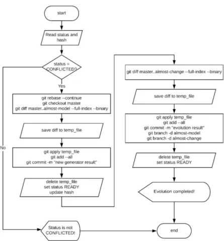
4.14 Flowchart describing almost-git evolve [src] command . 40 4.15 Flowchart describing almost-git evolve –continue com-mand . . . 41
4.16 Flowchart describing almost-git evolve –abort command 42 5.1 Quiz Game: IFML model . . . 45
5.2 Quiz Game: from prototype to final product . . . 46
5.3 Media Player: IFML model . . . 46
5.4 Media Player: from prototype to final product . . . 47
5.5 IFMLEdit.org . . . 48
5.6 WebRatio Enterprise Platform . . . 50
List of Tables
5.1 Quiz Game: Model & Code Co-evolution development statistics with IFMLEdit.org . . . 54 5.2 Quiz Game: Template-based forward engineering
devel-opment statistics with IFMLEdit.org . . . 54 5.3 Media Player: Model & Code Co-Evolution development
statistics with IFMLEdit.org . . . 55 5.4 Media Player: Template-based forward engineering
de-velopment statistics with IFMLEdit.org . . . 55 5.5 Quiz Game: Model & Code Co-evolution development
statistics with WebRatio . . . 57 5.6 Quiz Game: Template-based forward engineering
devel-opment statistics with WebRatio . . . 57 5.7 Media Player: Model & Code Co-Evolution development
statistics with WebRatio . . . 58 5.8 Media Player: Template-based forward engineering
de-velopment statistics with WebRatio . . . 58 5.9 Quiz Game: collisions with collision prevention rules . . 63 5.10 Quiz Game: collisions without collision prevention rules 63 5.11 Media Player: collisions without collision prevention rules 64 5.12 Media Player: collisions with collision prevention rules 64
Chapter 1
Introduction
Time to market is very important in the IT industry. Companies are constantly looking for tools that allow the developers to obtain a high quality final product as quickly as possible.
Model Driven Development has emerged as one of the leading ap-proaches for enabling rapid, collaborative application development.
1.1
Model Driven Development
Model Driven Development (MDD) is the branch of software engineer-ing that advocates the use of models and of model transformations as key ingredients of software development. The use of models allows de-velopers to focus on key aspects of the system while omitting details of secondary importance. A model is an abstract representations of a system that conforms to a unique meta-model. A meta-model defines the modeling language, i.e. the constructs that can be used to express models. A model conforms to its meta-model in the way that a com-puter program conforms to the grammar of the programming language in which it is written.
Developers use modelling languages to specify system requirements under one or more perspectives. We can group modeling languages in two classes:
1. General purpose modeling languages, such as UML (Unified Mod-eling Language [1]), are intended to provide a way to visualize the design of a system.
2. Domain specific modeling languages, such as IFML (Interaction Flow Modeling Language [2]), allow the developer to represent one or more specific facets of a system.
Domain-specific modeling languages tend to support higher-level abstractions than general-purpose modeling languages, so they require less effort and fewer low-level details to specify a given system.
The other key components of Model Driven Development are model transformations. Model transformations can be thought of as programs that take models as input. Distinguishing the type of output generated by the model transformations we can classify the transformations into:
1. Model to Model (M2M) transformations.
They translate between source and target models, which can be instances of the same or different meta-models. Figure 1.1 shows an example of Model to Model transformation where Place Chart Nets (PCN) are used to describe the semantics of IFML [3]. In [4], Statecharts are used to define the semantics of WebML, in [5] GraphQL is used to express queries on Web API’s inferred from a structural (UML) and behavioral (IFML) descriptions.
2. Model to Text (M2T) transformation.
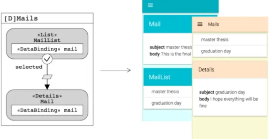
They focus on the generation of textual artifacts from models. Figure 1.2 shows a Model to Text transformation where a GUI implementation is generated from an application model [6]. The transformation generates HTML code from the corresponding el-ements in the input model. Another example is described in [7] where a RESTful Web API implementation is generated from a high level description.
1.1.1 Key aspects
Abstraction is far the most key aspect of Model Driven Development. It allows developers to represent important aspects of a system, omitting details of secondary importance. However if the target meta-model has an higher expressive power than the source meta-model, the latter may not contain enough information to drive the production of a unique output, due to its abstraction level.
A relevant example of this situation are User Interfaces (UI), and in particular web based ones. Model abstraction enables reasoning about
Figure 1.1: Example of Model to Model transformation
Figure 1.2: Example of Model to Text transformation
the organization of the front-end and about the essential interactions, regardless of presentation details. However aspects, such as content layout, fonts, colors, or gestures, must be addressed after the core GUI design is complete, because their quality greatly influences the final user experience.
Figure 1.3: Multiple valid target from the same input model
Figure 1.3 shows an example where GUI implementation is gen-erated from an application model [6]. Starting from the same IFML model more than one possible visual representation can be produced, by taking different decisions about the layout and the style. Another example is the generation of a RESTful Web API implementation from a high level description [7]. Alternative implementations can be pro-duced, by taking different decisions about various aspects of the archi-tecture such as storage and security.
Transformations should map each valid source model into one valid target model deterministically. The developer is responsible of direct-ing the transformation so to select the alternative that best suits the requirements not captured by the input model.
Pure Forward Engineering
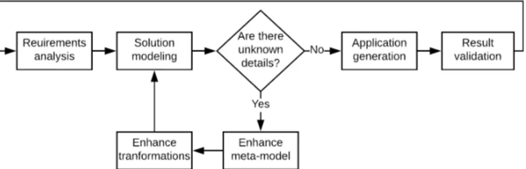
A pure Forward Engineering approach, whose flowchart is shown in Figure 1.4, requires unknown details to be solved by enhancing both the source meta-model and the transformations, to remove uncertainties and maintain a unidirectional flow from model to code.
Figure 1.4: Flowchart describing Forward engineering approach
However, such an approach can lead to loss of abstraction in the source model and diminishes the benefits of the MDD methodology. Template based forward engineering
Inspired from the forward engineering approach, template-based ap-proach has been successfully adopted in the industry. It advocates the use of templates, i.e. code skeletons that the generator must fill-in to produce the executable code, to build Model to Text transformations. The transformation exploits the expressive power of the target meta-model to expand to a greater detail the concepts defined in the source model. The transformations select specific features of the output not inferable from the input model.
Many commercial tools such as WebRatio [8], Mendix [9], Outsys-tem [10] and Zoho Creator [11] require developers to annotate high-level models with ad hoc attributes, so that the M2T transformation can se-lect the proper presentation template and create the desired output. The template-based approach introduces an additional source of com-plexity: the construction of templates could demand more work than manual coding of the final artifact, especially for applications with very specific presentation requirements. The construction of templates usu-ally demands some extra knowledge: besides knowing the programming language to be generated, the developer must know the language used to build the template logic.
Problem Statement
The alternative approach to the use of template-based transformations is to exploit MDD tools for the creation of the first prototype of the
application. The developers are then allowed to manually extend the code to incorporate the aspects abstracted by the input model and by the transformations that apply to it.
The obvious downside of this method is the misalignment between the model and the code. After a model change the code generated does not preserve the manual changes that the developer implemented. This problem hinders the use of transformation throughout the whole life cycle of the application.
The thesis focuses on the development of projects involving MDD tool-chains, with particular attention to the problems of co-evolving the model and the code. We propose a workflow whereby MDD tools and developers are considered as equals and can both update the source code of the application, in a way that preserves the modifications in-troduced by both human and automated developers.
1.2
Contributions of the thesis
The contributions of the thesis can be summarized as follows:
• We propose a distributed development and co-evolution workflow, which considers developers and MDD tool-chains as peers and helps them cooperate. The workflow captures the similarities be-tween distributed development and model and code co-evolution and resolves conflicts between the code produced by developers and by tools in a general way, which does not depend on the specific characteristics of the model transformation tools.
• We identify the families of conflicts that arise in a workflow inte-grating human coders and automated tools, characterize their ori-gins and propose both automatic resolutions or mitigation strate-gies.
• We showcase the power of the proposed approach via a reference implementation and evaluate its impact on two use-case applica-tions.
1.3
Document Structure
The thesis is organized as follows: Chapter 2 will survey model-based and text-based approaches for the evolution of textual artifacts.
Chap-ter 3 will propose a workflow which allows developers and MDD tool-chains to co-evolve the same code-base and survey the type of conflicts that can arise and how to prevent or mitigate them. Chapter 4 will dis-cuss the algorithm from a practical point of view presenting a reference implementation. Chapter 5 will evaluate the effect of the proposed ap-proach on the development of two projects. Finally, Chapter 6 draws the conclusions and gives an outlook on future work.
Chapter 2
Related Work and State of
the Art
In this Chapter we will survey various techniques that allow develop-ers to build customized applications using Model Driven Development tools. According to the forward engineering approach developers have to enhance both the meta-model and the transformations. In this way developers are able to specify the details that are not inferable from the original model. In Section 2.1.1 we will survey the techniques used to enhance the meta-model. In Section 2.1.2 we will survey the techniques used to enhance or replace model transformations, with particular fo-cus on model to text transformation and template based approach. In Section 2.2 we will survey model and code co-evolution techniques that allow the developers to synchronize models and source code. At the end, in Section 2.3 we will survey state of the art tools that allow developers to work concurrently.
2.1
Forward engineering approach
The source meta-model, due to its abstraction level, may omit details needed to drive the model transformation to produce a unique output. A Forward Engineering approach requires such details to be specified enhancing both the source meta-model and the model transformations.
2.1.1 Evolution of meta-models
Although modeling is an activity regulated by meta-models, currently there are no commonly accepted mechanisms to define how meta-models can be extended. In [12] the authors propose a mechanism that allows specifying customization and extension rules for meta-models. The proposed approach has the advantage that it is non intrusive, and generic, that is, extension rules can be linked to any meta-model.
In [13] the authors focus on improving the agility of modeling frame-works by allowing them to be more flexible and adaptable to changes on the meta-models they provide support for. They propose a lightweight meta-model extension mechanism, based on a textual domain specific language for specifying meta-model extensions.
In [14] the authors use UML as reference modeling language. It has been widely used for modeling applications and changes continu-ously. They analyze the evolution of the meta-model by using complex network and information entropy technologies. The approach can pro-vide insight into the constructive mechanism and future trends of the examined meta-model.
Meta-models are evolving over time, requiring existing domain mod-els to be co-evolved. Various solutions have been proposed to solve the problem of meta-model and model evolution. A vision of co-evolution between meta-models and models through consistent change propagation is presented in [15, 16]. The approach addresses co-evolution issues without being limited to specific meta-models or evolution sce-narios. It relies on incremental management of meta-model-based con-straints that are used to detect co-evolution failures, generating sug-gestions for correction when a failure is detected.
The high number of solutions makes it difficult for practitioners to choose an appropriate approach. In [17] a survey of approaches to support meta-model and model co-evolution is presented, introduc-ing a taxonomy of solution techniques and classifyintroduc-ing the existintroduc-ing ap-proaches. They also use the results to provide a decision support for practitioners, who aim to adopt solutions from research.
2.1.2 Evolution of Model-to-Text transformations
Model to text transformations are at the base of MDD workflows. Given the template-based nature of most such transformations,
com-plexity can easily arise from the creation and maintenance of templates [18]. Various approaches and tools have been devised to enhance or re-place M2T transformations.
In order to avoid the need of M2T transformations, in [19] the authors show how efficient, platform-specific code can be generated out of DSL programs using specialization of an interpreter for the DSL by partial evaluation.
In [20] the authors propose a design pattern that allows for the decomposition of complex templates with branching and conditions in-side into simpler ones. The code generator does not know about the concrete templates that are called. The pattern results in a flexible code generator with simple templates, good extensibility and separa-tion of concerns. This agility also facilitates the design for extension and changes.
Complexity can arise from changes in both source meta-model and target technologies. In [21] the authors propose a definition for a stan-dard problem to evaluate the evolution support in M2T transforma-tion systems, with the objective to allow for benchmarking of multiple evolution-support techniques for M2T transformations.
In [18] a survey of possible approaches to organize model transfor-mations is conducted, showing the effects of moving rapidly evolving aspects of the architecture from the M2M transformations to the M2T transformations and even outside of the MDD workflow as an abstrac-tion layer managed manually.
The above mentioned approaches exploit specific features of the in-put and outin-put meta-models and of the transformation infrastructure. The approach discussed in this thesis moves a step further, overcom-ing dependencies from languages and use-cases. Instead of definovercom-ing a strong separation between the code generated by M2T transforma-tions and the code managed manually, we investigate a general-purpose method, independent of the input and output meta-models and of the transformation tools, in which the boundaries between the two regions of the code (human and tool-generated) can be set flexibly and changed over time.
2.2
Model and code co-evolution
Model and code co-evolution techniques have been explored to simplify M2T transformations. In [22] a bidirectional M2T transformation ap-proach based on Triple Graph Grammar (TGG) is discussed. The Ab-stract Syntax Tree (AST) representation of the target language is used in a bidirectional M2M transformation defined via TGG. The AST is structured with particular attention to supporting extra chunks of text that can be introduced during manual modifications, but are not di-rectly managed by the transformation. In general, addressing text-level changes by lifting them at the model level can reduce the complexity of modeling and transformation, at the cost of defining a parser specific for the target language and a reverse mapping from low level code to the high level concepts, which is normally defined for a limited class of code-level patterns. In [23] a trace based framework for change retain-ment is proposed, which helps tracing back code-level modifications to the model. Both bidirectional and trace-based approaches are bound to the target languages.
The need to support different languages or new features of a target language requires changes to be propagated to the transformation and tracking chains. The approach proposed in this thesis poses minimal requirements on the way M2T transformations should structure the generated code and works mostly on the output of the transformations, in a language and tool-independent way.
Approaches have been proposed to allow the developers to manually modify the output of Model to Text transformations while preserving such manual modification across multiple execution of the transforma-tions. Acceleo [24] use protected areas to automatically concentrate manual editing to specific portions of the code and leave the majority of the generated code untouched. However a sharp division between structure and style is not always achievable, especially when rapid evo-lution is required. Many modern frameworks, such as Framework7 [25], Flutter [26] and others moved towards an effective compromise between separation of concerns and development costs.
2.3
Distributed development
Distributed development is essential to speed up application develop-ment. Developers need tools that allow them to cooperate easily and to
provides control over changes to source code. Version Control Systems (VCS) have been developed to fulfill this requirement.
Version Control Systems like Git [27], Mercurial [28] or SVN [29] also manage conflict resolution.
Conflict resolution at text level has been studied for a long time, providing automatic resolution and leaving the manual intervention of the developer as a fall-back. In [30] a coarse grained technique is pre-sented to provide the foundation for building an automatic program-integration tool. In [31] the proposed algorithm exploits the fine-grained edit operation history of Java source code and extracts only the edit operations that affect the revision of a particular class member alleviating the task of merging conflicting revisions.
Our approach exploits the well-proved capabilities of conflict reso-lution tools to support the co-evoreso-lution of the application model and of code generated from it, by enabling the merge of the code produced by programmers and by model transformations. Even if not all conflicts can be resolved automatically, in Chapter 5 we show that the number of conflicts that require human intervention is comparable or less than the number of changes at transformation level needed to obtain the same result.
Chapter 3
Proposed Approach
In Section 3.1 we analyze how the software developers’ community deals with parallel development of software features. Then, in Section 3.2, we show similarities and differences between parallel development and model and text co-evolution. In Section 3.3 we propose a solution to apply the parallel development methodologies to the co-evolution of model and text, by treating the MDD tool-chain as yet another de-veloper in the team. Finally, in Section 3.4 we investigate on how the proposed approach can be integrated with automatic conflict resolu-tion.
Given the generic nature of the approach, the described work-flow is independent of the Version Control System (VCS), modeling and development language, and transformation framework.
Before proceeding, we introduce the concepts and notations used in the rest of the thesis.
• Developer: Di denotes the i-th member of the development team.
• Local/central code base: Ci denotes the version of the code-base edited by developer Di. CC identifies the central code-base shared among developers.
• Revision: Ri,j denotes the j-th revision of code-base Ci; it is the full textual artifact stored in Ciat a particular point in time. RC,j denotes a revision in the central code base.
• Equivalence: two revisions Ri,j and Rm,n are equivalent, if the content of the textual artifact stored in them is the same.
• Difference: the difference Ri,j− Rm,n of two revisions is the set of changes that need to be applied to Rm,n to produce Ri,j. • Delta: the delta introduced by Ri,j (∆i,j = Ri,j − Ri,j−1) is the
difference between Ri,j and the previous revision Ri,j−1.
• Conflict: let n be the number of revisions in the central code-base CC; a revision Ri,j is said to be in conflict with CC if Ri,j−1 in not equivalent to RC,n, or if j is equal to 1. In other terms, a conflict signals that a new revision has been produced starting from a newly initialized code-base or from a version different from the last one consolidated in the central code base.
• Submission: let n be the number of revisions in the central code-base CC; the submission Ri,j → CC is the act of creating a shared revision RC,n+1 in CC which is equivalent to the local revision Ri,j. A submission is always performed from a local code-base Ci to the central code-base CC. If Ri,j is not in conflict with CC, the submission Ri,j → CC generates RC,n+1, in such a way that ∆C,n+1is equivalent to ∆i,j. Note that Ri,j is equivalent to RC,n+1, by the definition of submission, and Ri,j−1 is equivalent to RC,n, by the definition of conflict. The submission of a non-conflicting revision Ri,j is always accepted. The submission of a revision in conflict is by default rejected, to avoid the possible loss of local changes and prompt the developer to solve the conflict. A conflicting submission can be forced, overriding the default. • Conflict Resolution: let n and m be the number of revisions
in the local code-base Ci and in the shared code-base CC respec-tively; the conflict resolution RC,m 7→ Ci is the act of creating a (local) revision Ri,n+1 based on both RC,m and Ri,n. Note that Ri,n+1 may be equivalent neither to RC,m nor to Ri,n. The objec-tive of conflict resolution is to enable a submission from a devel-oper even if he has worked on a version that is out of synch with respect to the central code base. Solving a conflict between RC,m and Ci allows a submission Ri,n+1 → CC to be performed, even if Ri,n → CC was previously rejected due to a conflict.
When a revision Ri,nis in conflict with CC the developer can solve the conflict by generating a new revision Ri,n+1. Performing the operation on Ci instead of CC allows other developers to continue
their work without interference. After the resolution is performed, the developer can submit Ri,n+1 to CC.
• We refer to a revision of the code-base that results from a man-ual change as RMi,j (manual revision), to a revision containing generated artifacts as RGi,j (generated revision), and to a re-vision that results from conflict resolution as Ri,jR (resolution revision).
3.1
Parallel & Distributed Development
During day to day operations, teams must deal with the problem of parallel development, whereby different subjects introduce distinct new features into the code-base independently. A common development work-flow on an ongoing version of a system is the following:
1. Developer D1starts the current development sprint with an empty local code base C1.
2. She aligns to the current status of the project by initializing her local copy C1 to contain n revisions imported from the central code base (R1,j = RC,j) for j ∈ {1..n}.
3. She introduces a new feature by applying changes on top of R1,n, creating a new revision RM
1,n+1.
4. She makes a submission to the centralized code-base generating a new revision: RM
1,n+1→ CC = RC,n+1M . RC,n+1M is accepted, because RC,n = R1,n.
5. She deletes her local copy of the code-base C1 returning to the initial state. Her work is safely stored in CC.
After such a work-flow, the revision history shown in Figure 3.1 is achieved.
When two developers D1 and D2 work in parallel on the same sys-tem, the work-flow may look like the following:
1. Developers D1 and D2 create their local copy C1 and C2 of the code-base from the current content of the central code base CC, which comprises n revisions; then ∀j∈{1..n}R1,j = RC,j = R2,j.
Figure 3.1: Development without Conflicts
2. D1introduces a new feature by applying changes to R1,n, creating a new revision RM1,n+1.
3. At the same time and independently D2 introduces another fea-ture, by applying changes on top of R2,n, creating a new revision RM
2,n+1.
4. D1 submits R1,n+1M to the centralized code-base generating a new revision RM
1,n+1 → CC = RMC,n+1. RMC,n+1 is accepted because RC,n = R1,n.
5. D1 deletes her local copy of the code-base C1 returning to the initial state. Her work is safely stored in CC.
6. D2 tries to submit RM2,n+1 to the centralized code-base. The op-eration is rejected because RM
2,n+1 creates a conflict with CC. 7. D2solves the conflict between RM2,n+1and CCgenerating RMC,n+17→
C2 = RR2,n+2.
8. D2 submits R2,n+2R to the centralized code-base generating a new revision RR2,n+2 → CC = RRC,n+2. The submission now is accepted because RR2,n+2is the result of the conflict resolution RC,n+1 7→ C2. 9. D2 deletes her local copy of the code-base C1 returning to the
initial state. Her work is safely stored in CC.
After such a work-flow, the revision history shown in Figure 3.2 is achieved.
This approach can scale to large number of developers who, before submitting their revision to the central code-base, are responsible to ensure that conflicts are resolved.
Figure 3.2: Development with Conflicts
Parallel development work-flows are commonly supported by Ver-sion Control Systems (VCSs), either distributed (e.g. GIT) or central-ized (e.g. SVN). Their functionality is not limited to content transfer and history tracking. Given a local and the central code-base Ci and CC with their respective latest revisions Ri,n and RC,m VCSs can iden-tify conflicts automatically. With the help of primitives specific to each VCS, it is even possible to automate, or at least simplify, conflict resolution. Various approaches can be applied to assist a resolution RC,m 7→ Ci: from simple analysis of the difference Ri,n− RC,m, to the more complex analysis of the full revisions histories of both the repos-itories. If two equivalent revisions RC,k and Ri,k0 are identified in the
histories of Ci and CC, the set {∆C,j | j ∈ {k..m}} of all the deltas in that history branch can be exploited in order to be reapplied step by step. In Chapter 5 we evaluate the results of the specific technique tested in our experiments.
3.2
Model and Text Co-Evolution
In an MDD-based work-flow, model-to-text transformations produce textual artifacts (e.g. code, configuration files, documentation, . . . ) from models. By allowing manual editing on the generated output to specify details not covered by the input model and by the code generation rules, it is possible to introduce conflicts with subsequent transformation executions based on evolved versions of the model. A na¨ıve approach to the resolution of such conflicts is the one realized by the following work-flow:
1. Development starts with a phase of modeling and code generation. Thus, the central code-base initially contains a single revision RG
C,1 which is the result of the first execution of the transformation. 2. Developer D1 creates a local copy C1 of the code-base CC, which
contains one revision. RG1,1 = RGC,1
3. She introduces a manual change on top of R1,1G producing a new revision RM1,2;
4. She submits the new revision to the centralized code-base gen-erating a new revision RM
1,2 → CC = RMC,2. The submission is accepted because RC,1 = R1,1.
5. She deletes her local copy of the code-base C1 returning to the initial state. Her work is safely stored in CC.
6. She evolves the original model and is ready to execute the trans-formation again.
7. She executes the transformation and stores the result into an a new empty code-base C1 initializing it with the new purely gen-erated RG
1,1 (different from RGC,1), which reflects the current state of the model at the code level. Note that manual modifications of the code introduced at step 3 are not reflected in the newly initialized local code-base, because the code generator is blind to manual modifications and would overwrite them anyway.
8. She tries to submit RG
1,1 to the centralized code-base. The oper-ation is rejected because RG
1,1 is in conflict with CC. Rejection occurs due to the way code generation works: C1 contains just one revision and is not created by evolving a preceding shared revision in the central code base.
9. She solves the conflict between RG1,1and CCgenerating an updated local copy that reconciles the manual changes stored in the central code-base and the new code generated after the model update (RMC,2 7→ C1 = R1,2R ).
10. She submits the new revision to the centralized code-base generat-ing a new revision RR
1,2 → CC = RRC,3. The submission is accepted because RR
11. She deletes her local copy of the code-base C1 returning to the initial state. Her work is safely stored in CC.
After such a work-flow, the revision history shown in Figure 3.3 is achieved.
Figure 3.3: Conflict resolution after manual change
3.3
The Virtual Developer
The developer D2 in Section 3.1 works on an outdated version of the code-base (Figure 3.2), which requires the conflict to be solved. The Model-to-Text transformation in Section 3.2 generates a revision RG1,1 (Figure 3.3) in conflict with the central code base due to the previous manual update of the generated code. These two scenarios are different with respect to the agent whose changes generate the conflict, but the evolution of the textual artifact follows a similar path.
In work-flow of Figure 3.3 the newly generated revision RG
1,1 is used to initialize a new code-base C1 due to the fact that the Model-to-Text transformation does not proceed by evolving the code-base incremen-tally, as real developers do, but always regenerates the whole textual artifact from scratch. At every transformation step, it would be as if an update on the entire artifact is checked in to the repository re-gardless of the past history. Given this observation, the work-flow of Figure 3.3 is equivalent to the one of Figure 3.4: at each model update and code generation step, the developer creates a fresh local copy C1 of the code-base CC, up to the latest purely generated R1,1G = RC,1G , before overwriting it with the new purely generated revision RG
1,2.
It is important to notice that the initialization of the local code base with the latest purely generated revision before a code genera-tion step makes it is possible to compute the delta ∆G
1,2 introduced by RG
1,2. Even though the Model-to-Text transformation overwrites the entire artifact, ∆G
1,2 singles out exactly the incremental changes that 21
Figure 3.4: Conflict resolution after manual change, alternative path
the Model-to-Text transformation induces over the previously gener-ated revision RG1,1 due to the model update. This initialization method makes the behavior of the code generator more similar to that of the human developer, who extends the code base incrementally.
Besides the difference in the initialization of the code base, the manual and automatic generation of the artifacts follow the same path, as visible by comparing the work-flow of Figure 3.2 and the one of Figure 3.4. Revisions RM
2,n+1, of Figure 3.2, and RG1,2, of Figure 3.4, are comparable: both generate a delta (∆M
2,n+1 and ∆G1,2 respectively), which embodies the changes w.r.t. a preceding revision (RM
2,nand RG1,1) in an outdated code-base (C2and C1 respectively) generating a conflict with CC.
Given such similarity, a Model-to-Text transformation can be con-sidered as a Virtual Developer, who always generates a conflict with CC. Treating the Model-to-Text transformation as an additional de-veloper potentially simplifies the management of manual updates in the forward engineering MDD life cycle. Tools and methodologies that are normally applied for conflict resolution among developers can be applied to both Human and Virtual Developers. Multiple Human de-velopers and a Virtual developer can work in parallel, in a work-flow such as the following:
1. CC contains n revisions, the latest revision RGC,n is purely gener-ated.
2. A Human developer DH creates a local copy CH of the code-base CC. ∀j∈{1..n}(RH,j = RC,j)
3. DH introduces a new feature by applying changes to RGH,n, creat-ing a new revision RMH,n+1.
gener-ating a new revision RM
H,n+1 → CC = RMC,n+1. The submission is accepted because RC,n = RH,n.
5. DH deletes her local copy of the code-base CH returning to the initial state. Her work is safely stored in CC.
6. The model is updated and the transformation is ready to be exe-cuted.
7. The Virtual developer DV creates a local copy CV of the code-base CC up to the latest purely generated revision: ∀j∈{1..k}(RV,j = RC,j), where k is the index of the last generated revision (k = n in the current example). In this way, the Virtual Developer aligns its local code base to the status that reflects the previous version of the model.
8. DV executes the transformation and stores the result into CV generating a new revision RG
V,n+1, which is a replacement of the entire textual artifact.
9. DV tries to submit RGV,n+1 to the centralized code-base. The op-eration is rejected because RG
V,n is not equivalent to RMC,n+1, due to the intervening manual update of DH.
10. DV solves the conflict between RC,n+1M and CV generating RMC,n+17→ CV = RRV,n+2. In this step, the ∆GV,n+1 is used to identify the modifications introduced by the latest round of code generation, which simplifies, and even automates in some cases, the identifi-cation and resolution of collisions with the manual modifiidentifi-cations of the code, as explained in Section 3.4
11. In order to safely store the latest purely generated revision in the central CC for future alignment, DV forces the submission of RGV,n+1 to the centralized code-base, generating RGC,n+2.
12. DV submits the RRV,n+2 to the centralized code-base, generating a new revision RR
V,n+2→ CC = RC,n+3R . The submission is accepted because RG
C,n+2 is equivalent to RGV,n+1. It is important to notice that ∆C,n+3 is identical to ∆V,n+2, due to the previous forced submission, which saved in the central code base also the latest purely generated revision.
13. DV deletes its local copy of the code-base CV returning to the initial state. Its work is safely stored in CC.
Figure 3.5: Revisions history.
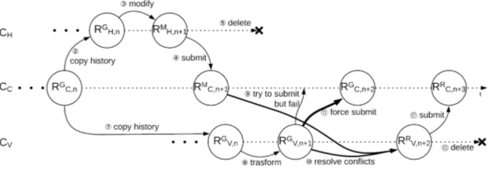
Figure 3.5 shows the revision history that results from considering the Model-to-Text transformation as an additional virtual developer. The central code-base now contains a twofold sequence of revisions: automatically generated (RG
C,i) and conflict-resolved (RRC,i+1). The Hu-man developer always updates the latest revision, whereas the virtual developer is always out-of-sync and applies changes on the latest gen-erated revision RG
C,i.
By preserving the generated revisions (RGC,i) in the code-base history we ensure that the delta ∆GV,n+1 can be interpreted as a mutation of revision RGV,n, which was generated by the previous execution of the Model-To-Text transformation. In Section 3.4 we will see how this interpretation of ∆GV,n+1is key in automating conflict resolution.
3.4
Automating conflict resolution
Given the definition of Conflict introduced at the beginning of the Chapter we can describe the Conflict Resolution RMC,n+1 7→ CV = RV,n+2R as any automated, manual or hybrid procedure which given the history of the code-base Ccup to RMC,n+1 and of Ci up to the latest revision RV,n+1G is able to generate a new revision RRV,n+2.
Policies are needed to prevent the insurgence of conflicts or else to mitigate them or at least support their automatic resolution. Current MDD tools automate the conflict resolution phase in different ways.
Template-based forward engineering
They avoid conflicts a priori, by disallowing manual updates to the gen-erated code. The revision produced by the conflict resolution RMC,n+17→ CV = RRV,n+2is always equivalent to RRV,n+2. This is possible thanks to the assumption that the code generator is the source of truth, so any manual changes introduced on code-base CC are ignored. This is the approach of template-based model-to-text transformations. The price to pay is the need of creating templates, a task that requires a kind of meta-programming, i.e., the programming of partial examples and code skeletons that the generator must fill-in to produce the executable code. This effort requires non-standard programming skills and is tied to the specificities of the MDD tool.
Protected areas
They automate conflict resolution by means of protected areas, i.e., identifying the regions of the code that the generator cannot overwrite. Each area is associated with a unique signature. The content of revision RG
V,n+1 is used as base artifact to build RRV,n+2. If a signature is present both in RM
C,n+1 and RGV,n+1 the content of the corresponding protected area is extracted from the artifact in central revision RM
C,n+1 and in-serted inside the matching protected area of the local revision RR
V,n+2. If a signature is present in RM
C,n+1 but not in RGV,n+1 the content of the corresponding protected area in the central RM
C,n+1is just discarded. It is important to notice that, while the developer is not involved in the conflict resolution, her intervention is needed to complete the protected areas whose signature is present in RG
V,n+1 but not in RMC,n+1. This ap-proach assumes that the aspects where human intervention is required can be sharply separated from the rest of the code, an assumption that is hardly verified in modern web and mobile applications, where the presentation is still entangled with the structure of the front-end.
Our aim is to relax these assumptions, acknowledging conflicts as the normal outcome of the integration between the virtual and human developers and performing conflict resolution following an hybrid ap-proach which exploits the history of the repository to automatically preserve manually introduced changes and involves the developer in those few cases in which the proper resolution is not clear to the tools itself.
3.4.1 Exploiting deltas
At any given point in the history of a project, the shared code-base CC and the local code base of the Virtual Developer CV may have diverged, due to the introduction of updates by human developers; however, thanks to the way in which the work-flow is managed, the two code-bases have an equivalent history up to the revisions RGC,n and RV,nG (Figure 3.5). These revisions contain the latest shared output of the model-to-text transformation.
After such ”synchronization point”, the centrally shared delta ∆M C,n+1 contains all the changes introduced by human developers posterior to RG
C,n and the local delta ∆GV,n+1 contains all the changes introduced by the Virtual Developer in the last (yet not shared) execution of the model-to-text transformation. These two deltas may interfere and the interference must be identified and resolved.
To support the resolution of a conflict, each delta must be decom-posed into the individual changes it contains. The following definitions characterize the content of a delta:
• Line: a tuple consisting of a unique identifier, a content and a position.
• Artifact: an ordered set of lines.
• Atomic update: an elementary modification of the artifact. Al-lowed atomic updates are:
1. Insertion: creation of a new line with given content at a position successive to an existing line or at the beginning of the artifact. The positions of the lines located after the new line are incremented.
2. Deletion: the removal of a line, with the consequent decre-ment of all the lines positioned after it.
• Update: a set of atomic updates affecting distinct lines at con-secutive positions.
• Collision: two updates ui and uj are in collision if there exist an atomic update ai ∈ ui and an atomic update aj ∈ uj affecting the same line.
• Update Graph: a undirected graph U in which vertexes are updates and edges, if present, denote the collision between them.
• Collision Group: a collision group UC is a connected component of the update graph having size greater than one, i.e., comprising at least one collision. An update graph with no collision groups is called a Collision-free graph UF; the updates contained in a collision-free graph can be applied independently.
• Collision Resolution: a procedure that takes in input a collision graph and produces in output a new collision free graph.
Conflict resolution can be achieved with the following steps: 1. ∆M
C,n+1 is decomposed into its collision-free updates UFM. 2. ∆GV,n+1 is decomposed into its collision-free updates UFG.
3. The set UC = UFM ∪ UFG is formed, which can contain collisions. 4. If UC contains no collision groups, the set of updates to apply U
is defined as: U = UC. Otherwise, collision resolution is applied, so to create a new collision-free graph UF and the set of updates to apply U is defined as: U = UF.
5. The updates in U , which are guaranteed non to collide, are applied to RG
V,n+1 generating RRV,n+2.
The above mentioned steps are supported in all industry standard VCSs. They automatically identify the set U , by decomposing ∆M
C,n+1 and ∆G
V,n+1. If no collision groups are identified they automatically produce RR
V,n+2. If one or more collision groups are identified they support the developer during collision resolution.
3.4.2 Reducing the number of collisions
Supposing that all the changes manually introduced by the human developer in the generated code are needed (thus the size of ∆M
C,n+1 cannot be reduced) the number of collisions can be reduced in tow ways:
1. Making human developer and virtual developer work on different lines.
2. Reducing the size of ∆G V,n+1.
Separation of concerns
The ability to identify areas (or even entire files) which are pure respon-sibility of the model-to-text transformation or, viceversa, are purely responsibility of the human developer can simplify conflict resolution. While perfect separation of concerns may not be always reachable, due to limitations of the target language or because the complexity which needs to be added to the project is not justifiable, it is always advisable. Files which should not be changed by the developer will never gen-erate conflicts, due to the fact that the only delta which introduces changes are ∆V,n+1.
Files which should be edited by the developer should be generated following a fixed and recognizable template, in order to make only ∆M,n+1 the one which introduces changes. Given the fact that these files are introduced and removed in ∆V,n+1 revisions and editing only in ∆M,n+1 revisions the resolution can be na¨ıve.
Separation of concerns can be applied even at the level of groups of lines or even single lines of text. Lines which are responsibility of both the developer and the transformation should be split exploiting one of the language invariabilities.
For example line level separation of concerns can be achieved by splitting HTML tags from a single line
<div class="list-item" data-bind="text: fields['title']"/>
to multiple lines containing each one a different attribute. At-tributes related to styling, responsibility of the developer, can be sep-arated from the ones related to behavior, responsibility of the model-to-text transformation, avoiding collisions.
<div class="list-item"
data-bind="text: fields['title']"/>
Accurate design of the transformations
Reducing the number of lines modified by the code generator decreases the likelihood of collisions.
A transformation should always deterministically produce the same code from the same model, also it should produce the same code from equivalent models, i.e. models differing just on meta-data (e.g. graph-ical information used during rendition in an editor). Non determinism
typically arises from the non-deterministic iteration over model ele-ments during code generation. It can be avoided if the transformation exploits a fixed criterion for model navigation based on semantically meaningful features, even if such criterion is not part of the model-ing language. For example, a model-to-text transformation generatmodel-ing code from an IFML DataFlow element can generate different artifacts depending on the order in which the parameter bindings are traversed. The following JavaScript code could be produced from an IFML data flow associated with two parameter bindings (title and author of a song).
var packet = {
'title' : data['song'],
'author' : data['author_name'] };
If the order in which the parameter binding sub-elements are tra-versed is not deterministic, the transformation can produce different outputs between two runs on the same input model.
var packet = {
'author' : data['author_name'],
'title' : data['song'] };
Chapter 4
Implementation Details
In this Chapter we will analyze how the workflow proposed in Section 3.3 can be mapped to a Git [27] workflow and present a reference implementation that we have used during our tests.
The proposed approach can be implemented with various Version Control System. For each VCS a specific workflow is needed. Git [27] as a distributed VCS, is aimed at speed, data integrity, and support for distributed workflows.
4.1
Git primitives
The concepts introduced in Chapter 3 can be mapped to concrete Git primitives as follows:
• code-bases are mapped to Git branches, i.e., parallel histories in-side a single Git repository.
• revisions are mapped to Git commits. Each commit is associated with a message and a hash computed as SHA-1 checksum. • the act of copying the central code-base is mapped to the clone or
branch Git operations, depending on the location of the central code-base; the former in the case of a centralized repository, the latter in the case of a local branch.
• submission is mapped to the Git push operation, which copies commits from the current branch to another local or remote one. The push operation may fail if the latest commit in the remote
branch (i.e., the HEAD of the branch) is not identified in the local branch.
• collision resolution is mapped to the rebase operation in Git.
The reader is supposed to be familiar with git commands and paradigms. We take as reference documentation the one available at [32].
4.2
Git workflow
The workflow shown in Figure 3.5 can be mapped to a Git workflow as follows:
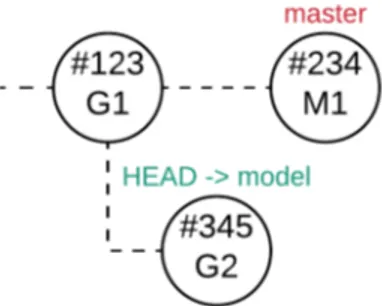
• The remote repository, shown in Figure 4.1, is composed only by the master branch and contains n commit s. The latest commit, having commit message G1, is purely generated.
Figure 4.1: Remote repository: initial status
• A human developer clones the remote repository into a local one. As shown in Figure 4.2 there is only the master branch and HEAD points at the master branch.
Figure 4.2: Local repository: initial status, clone of the remote repository
• The human developer manually introduces a new feature by ap-plying changes to G1. She stashes all the changes and commits with message M1 (Figure 4.3).
• The human developer uploads the content of the local repository to the remote repository. The remote repository (Figure 4.4) now stores the new features manually introduced by the human devel-oper.
Figure 4.4: Remote repository: manual changes are safely stored
• The human developer deletes the local repository. Her work is safely stored in the remote repository.
• The model is updated and the transformation is ready to be exe-cuted.
• The virtual developer creates a local copy of the remote reposi-tory and checkout the commit having message G1. In this way the virtual developer aligns its local code-base to the status that reflects the current version of the model. She creates a branch named model, as shown in Figure 4.5.
Figure 4.5: Local repository: the status reflects the current version of the model
• The virtual developer executes the transformation and stores the result into the repository (Figure 4.6), replacing the entire textual artifact. Then she stashes all changes and commit with message G2.
Figure 4.6: Local repository: new purely generated revision is safely stored in model branch
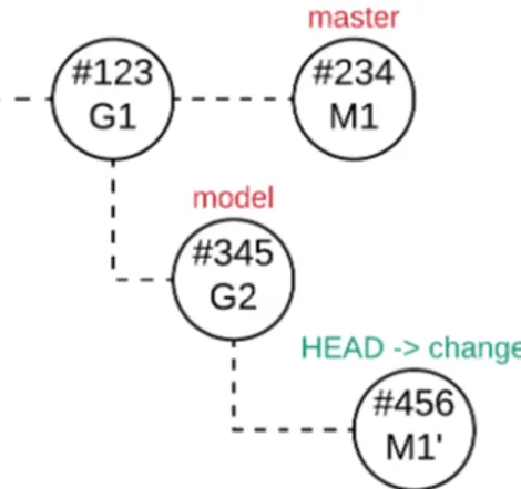
• In order to leave the master branch untouched the virtual devel-oper creates a new branch change starting from the latest commit of the master branch.
Figure 4.7: Local repository: new branch created from master branch
• A rebase operation is performed from the change branch onto the model branch, as shown in Figure 4.8. All the changes that the human developer made starting from the commit having message G1 are applied on top of the model branch, thus on top of the commit having message G2. During this phase conflicts may arise: some changes could not be directly applied to the commit having message G2 and human developer intervention may be needed to solve conflicts. The result is stored into the change branch, in a commit having message M1’.
Figure 4.8: Local repository: manual changes are applied on top of model branch
• Now the virtual developer has to store the results onto the master branch in order to push them to the remote repository. The virtual developer creates a commit G2 on the master branch. The artifact represents the current status of the model. This step is necessary for subsequent alignments.
• The virtual developer creates a commit having message M1’ on the master branch. In this way she stores in the master branch the result of the conflict resolution phase. The status of the local repository is shown in Figure 4.9.
Figure 4.9: Local repository: master branch is updated with new revisions
• The master branch contains all the information. The virtual de-veloper can now delete the other two branches (Figure 4.10).
Figure 4.10: Local repository: remove the unnecessary branches
• The virtual developer uploads the local repository content to the remote repository. The status of the remote repository is shown in Figure 4.11.
Figure 4.11: Remote repository: new purely generated revision and changes are safely stored
The human developer always starts working from the latest commit, while the virtual developer is always out-of-sync and starts working from the last purely generated commit.
4.3
Procedure automation
In this section we will present almostjs-git [33], a middleware system built on top of Git [27]. The proposed workflow has to be used ev-ery time a new model update is needed. The system must face two problems:
• It has to know what is the commit corresponding to the last generated revision.
• It has to allow the human developer to manually solve conflicts if needed and continue the procedure when conflicts are solved. 4.3.1 Status of the evolution process
The system must always know what is the status of the evolution pro-cess. We can identify 3 statuses of the evolution process:
1. undefined: The commit hash of the the commit corresponding to the last generated revision is not known. The evolution process cannot be executed.
2. ready: The hash of the the commit corresponding to the last generated revision is known and the evolution process has not started yet.
3. conflicted: The evolution process has started but manual con-flicts resolution is needed. The human developer can either abort the evolution process or resolve the conflicts and continue the evolution process.
A state-chart of the evolution process is shown in Figure 4.12. The status may change according to the command that the developer uses. The available commands are explained in Section 4.3.2.
Figure 4.12: State chart of the evolution process
Status file
The hash of the commit corresponding to the last generated revision and a string representing the status of the evolution process are stored in a json file. The content of the file when the status is ready is shown in Listing 4.1.
1 {
2 ” hash ”: ” c4a7 6a7”, 3 ” s t a t u s ”: ”READY”
4 }
Listing 4.1: Status file example
4.3.2 Available commands
The virtual developer is provided with commands to manage the evo-lution process.
$ almost-git init
The init command is necessary to allow the virtual developer to start using the other commands. It is responsible of initializing the repos-itory and the status file, setting the status to ready and saving the hash of the the commit corresponding to the last generated revision. A flowchart representing the operations executed by the init commands is shown in Figure 4.13.
Figure 4.13: Flowchart describing almost-git init command
$ almost-git evolve
The evolve command allows the virtual developer to start the evolution process. It reads and writes the status file in order to execute the various steps. The command accepts various options, used to drive the execution flow.
• $ almost-git evolve [src]
The virtual developer use the parameter src to specify the path of the folder storing the new generated artifact. The path is needed by the system to copy the artifact into the repository when needed. This option allows the virtual developer to start the evolution process. Figure 4.14 shows a flowchart representing the execution flow. During the execution of this process conflicts
may arise. In this case the status of the evolution process will be set to conflicted and the human developer will be asked to manually solve the conflicts and continue the evolution process. • $ almost-git evolve –continue
Conflicts may arise during evolution process. In this case the pro-cess is interrupted and the human developer is asked to manually solve conflicts. Once the human developer solved the conflicts she uses this command to continue the evolution process. A flowchart representing the execution flow of this command is shown in Fig-ure 4.15.
• $ almost-git evolve –abort
The human developer may prefer to abort the evolution rather then solving conflicts. The command allows the human developer to abort the execution process and restore the repository status to the initial state (as if the evolution process had never started). Details of the abort execution flow are shown in Figure 4.16. The system [33] can be easily installed via NPM [34]. It requires Git [27] and Node.JS [35] to work properly.
Figure 4.15: Flowchart describing almost-git evolve –continue command
Chapter 5
Experimental Study
In this Chapter we evaluate the proposed approach on the development of two applications:
• A Quiz Game, implemented as a Cordova [36] application. • A Media Player, implemented as web application.
The evolution of the applications is described in Section 5.1. The de-velopment environments are described in Section 5.2. In Section 5.3 we compare the proposed approach with a state-of-the-art template-based forward engineering approach. In Section 5.4 we investigate on how the adoption of conflict resolution guidelines in model to text transforma-tions may reduce the necessity of human intervention during conflict resolution. The source code of the development phases is available are available at [37].
5.1
Evolution of the applications
The applications are chosen due to their non na¨ıve requirements: ac-cess to remote resources, multimedia and hardware capabilities of the device. The development is based on IFML (Interaction Flow Modeling Language [2]) and follows an iterative approach.
5.1.1 Quiz Game
The development follows 4 steps. At each step, new requirements are introduced, and the application model is updated. Each step also re-quires the enhancement of the look and feel of the application.
1. Proof of Concept. The application allows the user to scan a QR code (requirement coming from the game dynamics itself). Once this step is completed, the game proposes the player a multi-choice question. Once the user selects an answer, the application gives the user the correct answer and returns to the initial state. 2. Explanation details. The application gives the user the correct
answer allows the user to investigate the explanation relative to the correct answer.
3. Secondary Game Mechanics. While the previous game me-chanics remain available, a new one is introduced in the game. The player can choose to do not scan the QR code and receive a series of question.
4. Internationalization. The game mechanics are kept unchanged, but the ability to select the game language is introduced.
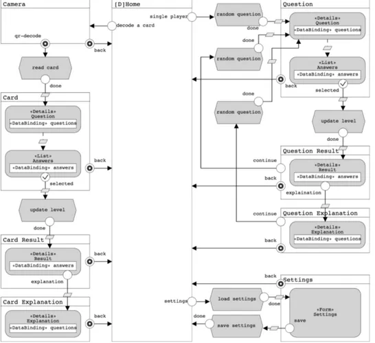
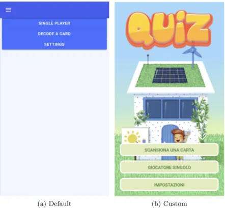
The IFML model is shown in Figure 5.1. Figure 5.2 shows the difference between the default UI generated by IFMLEdit.org and the final result.
5.1.2 Media Player
The second running example is a Media Player involving interaction with the media capabilities of the device and resources in the network. The development follows 4 steps:
1. Proof of Concept. The application loads a list of songs, allows the user to change song and pause/restart the currently playing song.
2. Styling. A custom style is applied to the user interface, and a system event is added to catch the end of a song.
3. Songs Filtering. An author filter is introduced in the applica-tion. The users can now filter the songs list in order to simplify the search.
4. Song Cover. The UI of the application is enhanced by showing the cover of the song currently playing.
The IFML model is shown in Figure 5.3. Figure 5.4 shows the difference between the default UI generated by IFMLEdit.org and the final result.
Figure 5.1: Quiz Game: IFML model
(a) Default (b) Custom
Figure 5.2: Quiz Game: from prototype to final product
(a) Default
(b) Custom
Figure 5.4: Media Player: from prototype to final product
5.2
Development environments
The approach has been implemented and evaluated with two different development environments:
1. IFMLEdit.org [6], an open-source environment for the rapid pro-totyping of Web and mobile applications.
2. WebRatio, a product for the development of Web and mobile application.
In this Section we describe the two development environments.
5.2.1 IFMLEdit.org
IFMLEdit.org [6] is an online environment for the specification of IFML models and the generation of prototypes of Web and mobile applica-tions (Figure 5.5).
Figure 5.5: IFMLEdit.org
In IFMLEdit.org, the model of the front-end is defined with IFML, the domain model is inferred from the IFML diagram, and actions are treated as abstract black-boxes.
IFMLEdit.org is built on top of the ALMOsT.js [38] transformation framework, which allows the developer to specify model transforma-tions with a rule-based extension of JavaScript.
1. Condition: a statement whose validity is checked for each model element.
2. Body: a function that is executed if the condition is satisfied. 1 c r e a t e R u l e ( 2 f u n c t i o n ( e l e m e n t , model ) { 3 r e t u r n model . i s V i e w C o n t a i n e r ( e l e m e n t ) ; 4 } , 5 f u n c t i o n ( c o n t a i n e r , model ) { 6 v a r c h i l d r e n = model . g e t C h i l d r e n ( c o n t a i n e r ) , 7 e v e n t s = model . g e t E v e n t s ( c o n t a i n e r ) ; 8 r e t u r n { 9 name : ' index . html ' , 10 c o n t e n t : r e q u i r e (' . / view−container −template . html . e j s ' ) ({ c h i l d r e n : c h i l d r e n , events : events }) } ; 11 } ; 12 ) 13 )
In this example each element is checked to be of type View Con-tainer. If the condition holds the children and the events of the View Container are retrieved and passed as parameters to the template.
Each template is build with the EJS (Embedded JavaScript tem-plates [39]) templating language. EJS requires the developers to build code skeletons to be filled with parameters.
1 <span> 2 <% f o r ( v a r i = 0 ; i < c h i l d r e n . l e n g t h ; i += 1 ) { −%> 3 <!−− <%= c h i l d r e n [ i ] . name %> −−> 4 <c−<%= c h i l d r e n [ i ] . i d %> params=” c o n t e x t : c o n t e x t ”></c−<%= c h i l d r e n [ i ] . i d %>> 5 <% } 6 f o r ( v a r i = 0 ; i < e v e n t s . l e n g t h ; i += 1 ) { 7 i f ( e v e n t s [ i ] . s t e r e o t y p e === ' system ' ) { −%> 8 <c−<%= e v e n t s [ i ] . i d %> params=” t r i g g e r : t r i g g e r . b i n d ($data ,'<%= events [ i ] . id %>')”></c−<%= events [ i ] . id %>> 9 <% } e l s e { −%>
10 <a c l a s s =” o p t i o n s ” data−b i n d=” c l i c k : t r i g g e r . b i n d ($data ,'<%= e v e n t s [ i ] . i d %>')”><%= events [ i ] . name %></a>
11 <% }
12 } −%>
13 </span>
In this example a template that generates the HTML of a View Container is shown. The children of the view container and the events related to the view container are traversed and for each of them a custom tag is generated.
IFMLEdit.org features a Web and a mobile code generator, both based on HTML, CSS and JavaScript. The former produces a client-side application, which can be connected to any preexisting REST ser-vice back-end. The latter produces a Cordova [36] application.
5.2.2 WebRatio
WebRatio is a commercial tool for the development of Web and mobile applications (Figure 5.6).
Figure 5.6: WebRatio Enterprise Platform
The tool enables the generation of the full code of the application. The user interaction is defined via IFML, the domain model via UML Class Diagrams, and the business logic via a proprietary Action Defi-nition Language.
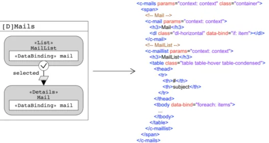
Details that cannot be modeled directly are incorporated using a template-based approach. An extension of IFML allows the developer to tag each IFML element with the custom template (Figure 5.7) to use for code generation.
The developer can create new custom templates or modify the ex-isting ones. The construction of templates requires the developers to be familiar with the Groovy scripting language and WebRatio Generation Tags. WebRatio has a build-in routine that checks for inconsistencies in the Groovy code and WebRatio Generation Tags. However, it does
Figure 5.7: WebRatio Enterprise Platform: template selection
not imply that the generated code is valid thus the developer has to validate it manually.
5.3
Model and code co-evolution vs Template-based
forward engineering
The use-case applications have been developed with both model and code co-evolution and the template-based forward engineering pro-cesses. Each sprint of the two processes shares the same phase of model editing, in which the model is updated and the code is generated. How-ever, the two processes differ in the way in which the manually devel-oped features are incorporated in the MDD loop. In Section 5.3.1 and Section 5.3.2 we describe the phases of the two processes focusing on the metrics used to compare the efforts. In Section 5.3.4 we provide examples to better highlight the differences in the two approaches. 5.3.1 Model and code co-evolution
Each sprint can be split in two different phases:
1. Conflict resolution. The previous manual changes are added on top of the generated code. The developer has to work on the parts
![Figure 4.14: Flowchart describing almost-git evolve [src] command](https://thumb-eu.123doks.com/thumbv2/123dokorg/7504993.104786/54.892.181.722.273.958/figure-flowchart-describing-almost-git-evolve-src-command.webp)