Alma Mater Studiorum · Università di Bologna
FACOLTÀ DI SCIENZE MATEMATICHE, FISICHE E NATURALI Corso di Laurea Magistrale in Informatica
STRUCTURED P2P VIDEO
STREAMING
AND
COLLABORATIVE FAILURE
DETECTION
Tesi di Laurea in Sistemi Distribuiti
Relatore:
Chiar.mo Prof.
VITTORIO GHINI
Presentata da:
PASQUALE PUZIO
Sessione II
Anno Accademico 2011/2012
Contents
1 Introduction 9
1.1 Benefits of P2P Video Streaming . . . 9
1.2 Requirements for P2P Streaming . . . 10
1.3 P2P Streaming Taxonomy . . . 11
1.4 Performance Criteria for P2P Live Streaming . . . 15
1.5 Challenges and Issues . . . 16
2 Objectives 19 3 System Architecture 21 3.1 Hypercube Data Structure . . . 21
3.2 Dissemination Rule . . . 23
3.3 Adaptation of Hypercube . . . 26
3.4 Framework for P2P Streaming . . . 28
3.4.1 Software Entities . . . 29
3.4.2 File Organization . . . 31
3.4.3 Data Structures . . . 32
3.4.4 Data Structures for Failure Detection . . . 38
3.4.5 UDP Packet Format . . . 41
3.4.6 Block Types . . . 43
4 Population Variation 55 4.1 Departures . . . 55 4.2 Arrivals . . . 58 5 Failure Detection 61 5.1 Detection Strategy . . . 64 5.1.1 Implementation Details . . . 68 5.1.1.1 Piggyback . . . 68 5.1.1.2 Functions for Failure Detection Implementation . . . 69 5.2 Recovery Strategy . . . 74
6 Simulations and Experiments 76
6.1 Experiments on PlanetLab . . . 76 6.2 Experiments for Failure Detection . . . 80
7 Summary of Work Done 82
8 Conclusions 84
Acknowledgements
I would like to sincerely thank my supervisor, Patrick Brown, for the wonderful chance to work at Orange Labs and the constant support he gave me. It was a pleasure to work with him and spend much time discussing together on several aspects of my internship. I really liked his approach to research and his friendly way to interact with me. At the same time, he also managed to provide a great guidance and strong motivations which have been fundamental for the achievement of all objectives declared at the beginning of the internship.
Thanks to this experience, I found out my taste for research, so I can surely say that it has been the most important experience I have ever had in my professional life. I will keep for ever good memories of good times I spent at Orange Labs.
I have to thank also my parents for giving me all the necessary support to make my own choices and pursue this important goal.
Last but not the least, I would like to thank also my classmates and teachers for making the Ubinet Master a great learning experience.
Abstract
Il video streaming in peer-to-peer sta diventando sempre più popolare e utiliz-zato. Per tali applicazioni i criteri di misurazione delle performance sono:
• startup delay: il tempo che intercorre tra la connessione e l’inizio della ripro-duzione dello stream (chiamato anche switching delay),
• playback delay: il tempo che intercorre tra l’invio da parte della sorgente e la riproduzione dello stream da parte di un peer,
• time lag: la differenza tra i playback delay di due diversi peer.
Tuttavia, al giorno d’oggi i sistemi P2P per il video streaming sono interessati da considerevoli ritardi, sia nella fase di startup che in quella di riproduzione [8]. Un recente studio [5] su un famoso sistema P2P per lo streaming, ha mostrato che solitamente i ritardi variano tra i 10 e i 60 secondi. Gli autori hanno osservato anche che in alcuni casi i ritardi superano i 4 minuti! Si tratta quindi di gravi inconvenienti se si vuole assistere a eventi in diretta o se si vuole fruire di applicazioni interattive. Alcuni studi hanno mostrato che questi ritardi sono la conseguenza della natura non strutturata di molti sistemi P2P [3, 4]. Ogni stream viene suddiviso in bloc-chi che vengono scambiati tra i peer. A causa della diffusione non strutturata del contenuto, i peer devono continuamente scambiare informazioni con i loro vicini prima di poter inoltrare i blocchi ricevuti. Queste soluzioni sono estremamente re-sistenti ai cambiamenti della rete, ma comportano una perdita notevole in termini di prestazioni, rendendo complicato raggiungere l’obiettivo di un broadcast in realtime. In questo progetto abbiamo lavorato su un sistema P2P strutturato per il video streaming che ha mostrato di poter offrire ottimi risultati con ritardi molto vicini a quelli ottimali. In un sistema P2P strutturato ogni peer conosce esattamente quale blocchi inviare e a quali peer. Siccome il numero di peer che compongono il sistema potrebbe essere elevato, ogni peer dovrebbe operare possedendo solo una
conoscenza limitata dello stato del sistema. Inoltre il sistema è in grado di gestire arrivi e partenze, anche raggruppati, richiedendo una riorganizzazione limitata della struttura.
Infine, in questo progetto abbiamo progettato e implementato una soluzione personalizzata per rilevare e sostituire i peer non più in grado di cooperare. Anche per questo aspetto, l’obiettivo è stato quello di minimizzare il numero di informazioni scambiate tra peer.
Abstract
P2P broadcasting of video streams is increasingly popular. Important perfor-mance criteria on such applications are related to:
• startup delay: delay before start of playback when connecting to the stream (also called switching delay),
• playback delay: delay between source transmission time and peer playback,
• time lag: differences in playback delays between two peers.
However today’s most popular P2P live streaming systems suffer from long startup and playback delays [8]. A recent measurement study [5] over a popular P2P stream-ing system shows that typical startup and playback delays vary from 10 to 60 sec-onds. The authors also observe that, for most streams, some playback delays exceed 4 minutes! These are serious drawbacks for watching realtime events or using these applications for interactive streams.
Some studies have shown that these delays are a consequence of the mesh or unstructured nature of these P2P systems [3], [4]. A stream is divided into chunks that peers exchange. As a consequence of the unstructured dissemination, peers must constantly exchange information with their neighbors before forwarding the stream. These solutions are extremely resistant to network changes, but at the cost of losing their initial realtime broadcasting objective.
In this project we consider a structured P2P streaming system which has shown to offer great results with delays very close to the optimal ones. In a structured P2P system each peer knows exactly what block to send and to which peer. As population size may be very large, each peer should know what to do with a limited knowledge of the system. In addition, the system allows for arrivals and departures, even grouped, with limited reorganizations.
Furthermore, in this project we designed and implemented a custom solution to detect non-collaborative peers and replace them. Even for this aspect, the aim is to minimize the amount of packets exchanged between peers.
Chapter 1
Introduction
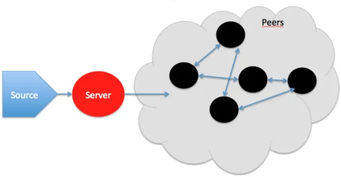
Peer-to-Peer (P2P) video streaming is a software-based solution that allows users to distribute data to a larger audience without using a single or limited set of central servers.
1.1 Benefits of P2P Video Streaming
P2P video streaming is extremely useful when the goal is to avoid system overload due to the high and unexpected number of simultaneous requests. In order to support an extremely large population, a large number of servers is needed, and in case the population increases more than we could expect, the system is not able to fulfill all the requests. Ideally, a P2P system is supposed to be able to scale and adapt its capacity to current requirements.
Furthermore, the population of a streaming system may be highly dynamic over the time, this means that if we use a centralized system, most of the time there will be a waste of resources due to the inactivity of some servers. A P2P system is much more efficient because every peer collaborates for content distribution, so there is no point in the system that allocates resources without using them at all.
We can clearly deduce that a P2P allows to dramatically reduce the cost for broadcast and make much simpler for any user to globally distribute a content
globally without any dedicated infrastructure.
More generally, P2P solutions are increasingly used by enterprises to provide high-quality and reliable services, especially for streaming, that can efficiently deal with limits of their infrastructures.
1.2 Requirements for P2P Streaming
In order to deploy a P2P system for streaming, there are some requirements that need to be fulfilled in order to make the system working in the proper way:
• Time Constraint: each piece of content we want to transmit, called block or chunk, has a playback deadline by which it has to be delivered to the destination peer. This means that a P2P system must meet a set of real-time requirements. In other words, if a peer receives a block after the maximum allowed time, that block can be considered lost because it is not useful anymore (not playable in case of video streaming).
• Scalability: potentially, a live streaming system may have a very high number of peers interested in transmitted content. A P2P system is ideally able to deal with very large populations without affecting the quality of the service achieved by connected peers.
• Heterogeneity: in the real world, it is very unlikely to have a set of peers with a homogeneous capacity, in terms of computational power, upload and download bandwidth, etc. A P2P system is thus supposed to be able to provide the best quality of service possible despite to the heterogeneity of peer resources.
• Grouped Arrivals and Departures: usually, it happens very often that a large number of peers wants to join (or leave) the system simultaneously.
This phenomena must not affect the normal working of the system. More practically, connected peers must not experience any additional delay or loss. • Decentralized Architecture: any P2P streaming, according to its defini-tion, is supposed to be resistant to multiple failures, so there must not be any possibility to have a single point failure or a bottleneck situation.
1.3 P2P Streaming Taxonomy
There are two main factors that characterize P2P systems:
• Topology: the structure, if any, adopted to organize the overlay network and create relations between peers.
• Delivery strategy: the way the system distributes pieces of content among peers. Each peer thus forwards pieces of content according to rules defined by the delivery strategy.
Nowadays, two approaches can be considered the starting point to design any other approach:
• Tree-based or Structured: in this approach, peers are organized according to a predefined structure and each peer has a precise position in that structure. Content is pushed from parent to child. Even relations and communication with other peers depend on the position of the peer in the structure. Generally, in this kind of systems there is an entry point which is in charge of placing a just joined peer into the structure.
• Mesh-based or Unstructured: in this approach, there is no predefined structure, peers establish relations and communicate by only exchanging in-formation with each other. As we can easily imagine, a larger amount of data needs to be exchanged compared to structured P2P systems, in order to keep
Generally, tree-based approaches prove to be scalable because they can easily handle very large populations, but they suffer from several factors. Indeed, they prove to be not robust in case of failures or nodes with poor resources. Indeed, the basic problem affecting tree-based approaches is the need of expensive re-structuring in case a peer stops cooperating or his upload capacity gets worse. Re-structuring may force peers to close ongoing connections with neighbors and run once again the procedure to get in the structure and change position. This could require to get aware of their new neighborhood and establish connections with new neighbors. We can state that the most important requirement for a structured P2P system is to repair the structure, in case of a peer churn, as efficiently as possible. In this case, efficient means minimizing both bandwidth and time.
Furthermore, they prove to be also not fair because a free-rider can easily make worse the quality of service provided to other peers and keep achieving a good quality for himself. However, they allow to achieve an interesting advantage: the implementation usually is much simpler.
Tree-based approaches can also adopt multiple trees. Peers belong to multiple trees at the same time but they can be internal nodes in at most one tree, in all the others they are leaves. In this kind of systems the stream is encoded in multiple sub-streams in order to ensure a minimum service quality even if some packets are lost. This helps also to handle bandwidth heterogeneity among peers. Another reason why multi-trees approach has been designed is to maximize cooperation and fairness between peers. Indeed, in a classic single-tree approach, peers in the last level (leaves) do not cooperate at all, they just receive content without collaborating for its distribution. To the best of our knowledge, there is no commercial system based on a tree-based structure.
In mesh-based approaches peers receive content by sending request packets to their neighbors. Each peer maintains a limited and random set of peers. In a pure
Figure 1.1: An example of tree-based P2P system
Figure 1.3: An example of mesh-based P2P system
mesh-based approach each peer selects a random set of peers and sends to them all the available blocks. Unfortunately, this approach generates a high waste of bandwidth because of duplicates. Indeed, it is very common that a peer receives a given block more than once.
Clearly, mesh-based approaches prove to be much more robust and adaptive compared to structured approaches. Differently from structured systems, a mesh-based system is completely mesh-based on cooperation, that is the reason why peers ideally have the tendency to create groups according to their capability to cooperate for global content distribution. This means that stronger peers with a high capacity (for both upload and download) will achieve a higher quality.
On the other hand, as in mesh-based P2P systems there is no structure and no specific rules for content distribution, peers need to continuously exchange syn-chronization packets (in some systems they are called request packets) in order to
efficiently distribute content. The most important task of a peer is to download (pull) blocks as quickly as possible from multiple neighbors. Both peer selection and piece selection has to be performed in such a kind of system.
1.4 Performance Criteria for P2P Live Streaming
Nowadays, most popular P2P live streaming systems suffer from extremely high de-lays. The most important performance criteria that characterize a P2P live stream-ing system are the followstream-ing:• Startup Delay: it is the time interval starting from the moment in which a peer connects to a online stream until the first piece of content has been received and is usable. In case of a video streaming system, the startup delay is considered as the interval between the connection request and the reproduction of the first video frame. In structured P2P topologies, this happens especially because when a peer asks to join the system, he needs to be assigned a position in existing structure and as soon as he gets one, he sends to other peers (neighbors) his coordinates and other information.
• Video Switching Delay: A peer who is already connected to a stream may want to switch to another channel. The time elapsed from the switching request until the moment in which the user can actually watch the first frame of new video stream is called video switching delay. Differently from what we could suppose, this delay could be even higher than than the startup delay. Indeed, before switching to the new video stream, the peer is asked to unjoin the previous stream, and this could take some additional time.
• Playback Delay: The playback delay is the exact difference between the time at which a block has been sent from the source of the stream and the time at which that frame is actually played by a peer. In structured P2P
systems, peers that are farther in structure from the source will experience increasingly long playback delays. What can happen here is that a block might be received after the maximum allowed threshold, this can cause some noises in the reproduction like small freezings or long disruptions.
• Time Lags or Display Lags: The difference between playback delays expe-riences by two peers. This could be very annoying if two users are very close from a geographical point of view, but one gets the video stream couple, or even more, of seconds before the other one. What would happen if the video stream is a live sport event?
As we said in the introduction, these delays can reach very high values. More precisely, according to measurements made by [5], typically startup and playback delays vary from 10 to 60 seconds, which is a very long time if we consider that during that time the user is forced to wait until the reproduction of the first video frame.
1.5 Challenges and Issues
As we all know, any user connected to a real wide network, especially the Internet, always experiences some issues. A P2P streaming system has to deal with these issues and minimize the impact of any kind of sudden and unpredictable event.
Generally, issues and challenges of a P2P streaming system can be summarized as follows:
• Delays and ordering: usually in the Internet, there is no warranty for maxi-mum delays or ordering, so any application must take into account these issues and provide a efficient way to solve them keeping the quality of service good enough. In case of a P2P video streaming system, another critical requirement is to minimize disruptions or freezings during the playback.
• Free riders and incentive mechanisms: in a P2P system the cooperation between peers is fundamental in order to achieve a good quality for all peers connected to the system. If even just one peer stops cooperating, the quality can dramatically decrease for many peers. This means that a P2P system must provide incentive mechanisms, in other words, when a peer does not cooperate anymore, or keeps cooperating but below the minimum threshold, also the quality of service achieved has to be decreased or, if necessary, that peer has to be forced to unjoin the system.
• NATs and Firewalls: this issue, compared with the two above, is less critical. Indeed, many P2P or client-server systems just ignore this issue. However, an efficient P2P system should provide a way to bypass this kind of issues and keep providing a sufficient quality of service.
• Node Failures or Misbehaviors: unfortunately, it can happen that a node (peer) fails unpredictably or starts misbehaving. In case of a failure, the system has to adopt an efficient (and possibly fast) strategy for failure detection and recovery. Instead, in case of misbehavior, the system should be able to detect the misbehavior of a peer and expel him. As we can imagine, handling failures is less complex, indeed several detection algorithms have been developed and deployed. On the contrary, misbehaviors are more complex to detect and need a careful analysis. As we will se later, we designed and implemented a basic but pretty good solution for failure detection and recovery, specialized for structured P2P systems.
• Dynamic Bandwidth and Limited Upload Capacity: as we said above, cooperation is fundamental in a P2P system. If the cooperation of a peer goes below the minimum allowed threshold or, even worse, a peer stops cooperating, many peers are going to achieve a lower quality of service, probably lower than the minimum required to keep the service suitable. Unfortunately, as
we know, the bandwidth achieved by a peer can vary over the time, and the upload capacity generally is limited. The goal of a P2P streaming system is to deal with these limitations, maximize the quality of service achieved by each peer and keep it as stable as possible.
Chapter 2
Objectives
The primary objectives of my internship can be summarized as follows:
• Improving stability and efficiently handling population variation: in any P2P system, especially in Live Video Streaming, peers connected to the system can quickly vary, both in terms of number and identity. For instance, it is quite common to observe a fast increase of the population during the initial phase of the transmission, and a fast decrease during the final phase. In addition, during the transmission, it can happen very often that peers connected from a very short time, get disconnected. This phenomenon is also known as zapping.
• Detecting and recovering failed or non-collaborative peers: for any P2P system, it is fundamental to adopt an efficient strategy for failure detec-tion and recovery. In addidetec-tion, the system should be able to detect and fix not only peer crashes, but also other kinds of issues, for instance peers that cannot correctly cooperate anymore because their upload capacity is not large enough.
As we said above, in a structured P2P system reorganizing the structure could be tricky and cause a domino-effect for several peers. In fact, both the design
information to be exchanged in case of a change in the structure and limit the need to be aware of a change to a limited set of peers. Structure reorganization is a very common event in structured P2P systems, which can be triggered by either a new arrival or a departure. In particular, a departure is considered spontaneous when a peer correctly unjoins the system by himself, and forced when a peer is expelled or crashed.
Clearly, we can imagine that structure reorganization has to be handled as effi-ciently as possible. In other words, not only the amount of data and the time have to be taken into account, but also the additional delay caused by a change in the structure, which should be as close as possible to zero.
A secondary objective of this internship was to create a porting for Windows. This has been achieved by using some specific precompiling instructions in order to include or exclude some snippets of code depending on the target architecture.
Chapter 3
System Architecture
In this section we will describe the strategy and the structure adopted for dissem-ination. In addition, we will explore the architecture of the system from a more technical point of view and we will analyze closely the components of the system and their roles.
3.1 Hypercube Data Structure
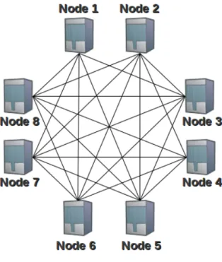
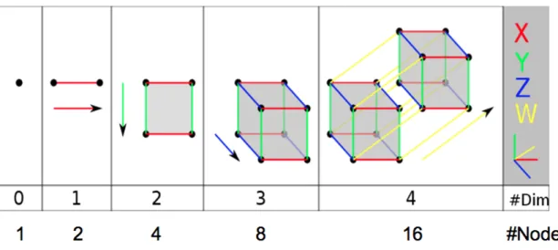
The structure on which our system is based is hypercube [6]. Hypercube is a mul-tidimensional structure in which every node corresponds to a vertex. For instance, if the number of dimensions is 3, the structure can host up to 8 nodes. Each node can be univocally identified through an ID, which is composed by a sequence of 0 and 1.
There are several reasons for which we can state that a hypercube is a suitable and efficient structure for P2P streaming:
• Simple enough to not require a large amount of packets to be exchanged in order to keep the structure consistent.
• Each peer knows exactly his position and his neighbors in the structure just by looking at his ID. This allows a peer to operate in the system without being
Figure 3.1: Hypercube Structure
aware of any additional information. In other words, once a peer gets the list of his neighbors and their coordinates, he can easily infer peers from whom he is going to receive blocks and peers to whom he is going to send blocks. • Time required for global transmission is proved to be optimal: log2N. This
allows to achieve shorter dissemination delays and a faster startup delay. • Highly scalable: number of peers is equal to 2 power number of dimensions.
This means that if population size increases very fast, we can double the maximum number of peers we can host in the system, by just increasing the dimension by 1.
Before proceeding and explaining dissemination rules, we need to introduce a couple of concepts that are fundamental for a good comprehension of the working mecha-nism of our system:
• Neighbor: Peer A is a neighbor of peer B if A’s ID has just one bit different than B’s ID. As we said above, any peer knows his neighbors by just performing basic operations on his own ID. This means that no matter what the context is, a given peer will always have the same set of neighbors.
1 in A’s ID. Level is a fundamental property for a peer. Indeed, as we will se later, the behavior of peer and his dissemination strategy depend on his current level.
An important issue occurs if peers are structured as a hypercube: a hypercube is supposed to be complete, in other words, every vertex should correspond to a node (peer). Formally, a hypercube is complete when, given a number of dimensions n, the number of peers is 2n. Unfortunately, it is very unlikely that the population of a
system is so stable to host for all the transmission the same number of peers. As we know, users of streaming systems can get disconnected in any moment, even after just a couple of seconds from their connection.
3.2 Dissemination Rule
Our aim is to design an efficient P2P system for live streaming. In this case, efficient means that the system should disseminate content as fast as possible and with the least waste of bandwidth. Ideally, each peer should not receive the same block twice but on the other hand losses have to be minimized even in presence of continuous and massive population variations.
Fairness is another important principle which has been adopted in the design of our system. Our dissemination rules provide a fair mechanism that equally share available bandwidth among peers.
In this section we will explain in detail the dissemination rule over a complete hypercube. In the next section we will explain the strategy we adopted in order to adapt the structure when the hypercube is not complete.
Two peers can exchange blocks if and only if they are neighbors, so we assume there is a relation one-to-one between peers such that it creates edges that link peers to each other. Blocks are thus exchanged along these edges.
• n is the number of dimensions;
• an identifier is defined in binary notation as a sequence of bits: bn 1. . . b1b0
with bi 2 {0, 1} for i = 0, . . . , n 1;
• let ekbe the n-length binary number with all zeroes except in position k modulo
n. Note that ek+n = ek. We denote the exclusive OR (or XOR operation) on
two n-length identifiers, a and b, the identifier c = a b, with ci = ai bi for
all i, where is the exclusive OR operator for bits. Two peers may exchange stream blocks if and only if their identifiers, a and b, differ by one bit (in binary notation);
• we denote peer b ek = bn 1. . . bk. . . b0 as the kth neighbor of peer b =
bn 1. . . bk. . . b0 (where bk is NOT bk in binary logic). In this definition k is
considered modulo n so that neighbors k and k + n of a given node represent the same peer.
As an example in an n = 5 dimension hypercube, the peer with identifier 18 has the binary representation b = 01001 and has the n hypercube neighbors (starting from neighbor 0 to neighbor n 1): 01000; 01011; 01101; 00001; 11001.
The source of the stream, i.e. the node with identifier 0, transmits stream blocks the following way: 0 transmits blocks numbered k to peer 0 + ek. For example with
n = 5the source will transmit blocks 3; 8; 13; ... to peer 01000.
To recursively describe the system we must explain how blocks received by a peer are retransmitted to its neighbors. The retransmitting rule is slightly different from the block generating rule used by the source.
A peer with identifier b, receiving a block numbered k, will perform the following algorithm.
I f :
bk = 1 : then r e t r a n s m i t chunk k to :
a l l k’ th neighbors such that bi=0 f o r a l l i=k ’ , . . . , k 1 the k th neighbor .
Note that indices are always considered modulo n. Also the retransmission should start with the smallest possible index k0 and continue by increasing the index until
reaching k.
These rules define a hypercube network and a broadcasting algorithm over this network. We will refer to them globally as the hypercube rule. They provide an optimal dissemination algorithm in terms of number of block retransmissions before reception by peers.
As an example, we can suppose that our identifier is 9 which in binary format is 01001. We suppose also that the number of dimensions is 5. As we can see in Figure 3.2, we are going to retransmit only blocks 0 and 3. Once again, we recall that indexes of blocks are considered always modulo n, where n is the number of dimensions. In the case of block number 0, we first apply the second part of the dissemination rule, which says that since the bit in position 0 is 1, we have to forward the block to 0th neighbor. To obtain the identifier of 0th neighbor we have just to to
invert the value of the bit in position 0. Now we try to apply the first part of the rule, which says that we have to retransmit the block to every neighbor such that in his identifier we can find a sequence of zeroes starting from any position until position k 1, where k is the block number modulo n. Sequences that wrap around are accepted too. In this case, we find one sequence that meets this condition, the one composed by only the bit in position 4. After applying the two rules, we know that we are going to forward that blocks to two peers: 11001 and 01000.
Figure 3.2: An example of application of dissemination rules
3.3 Adaptation of Hypercube
As we said in the previous section, the hypercube rule provides an optimal dissem-ination algorithm. However, it is very unlikely that a P2P system can manage to build a complete hypercube structure, so we need to design a solution in order to guarantee an efficient and optimal dissemination also in the presence of an incom-plete hypercube.
In addition, we need also to slightly adapt dissemination rules. Indeed, if we just apply the rules defined above, it is very likely that identifiers corresponding to some neighbors are not allocated yet. This happens because the system is incomplete and some positions are still empty.
Our solution changes just a limited portion of the peer organization and keeps meeting our main design principles: fairness, limited and local knowledge and limited reorganization. This solution is based on the notion of levels, in particular, the only levels affected by the change of dissemination rules are the ones that belong to either second-last level or last level.
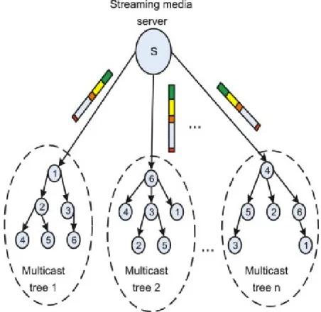
Previous solutions that have already been proposed to structure the diffusion for different values of N. But they are either limited to particular population sizes
Figure 3.3: An example of descendant list in last level [9, 10, 7] or the solution results in much longer delays [2].
Peer identifiers in level l may by classified in ⇣n 1 l 1
⌘
subsets Sj, where l is the
number of levels, so l is the last level, and n is the number of dimensions. Each subset is associated to one of the ⇣n 1
l 1 ⌘ identifiers, sj for j = 1, . . . ,⇣n 1 l 1 ⌘ as defined above. We recall that sj
0 = 1 and l 1 of the other n 1 bits are equal to
one. Let b be the identifier of a peer in the last level l. Let k be the position of its first non zero bit starting from the right (i.e. bk = 1and bi = 0for i = 0, . . . , k 1).
Then b belongs to the subset Sj such that one obtains the identifier sj by rotating b,
k times to the right. Note that sj belongs to Sj. As an example, if l = 4 is the last
level of system with dimension n = 8, and if sj = 00011001, then Sj is composed of
identifiers: • 00011001,
• 00110010,
• 01100100,
• 11001000.
Alternatively, the subset associated with identifier 10011001 contains only that iden-tifier. The identifiers belonging to in any subset Sj may be arbitrarily ordered so that
by increasing value. (In that case sj is the first identifier in the list Sj.) The routing
rules used by a peer in level l are the following. When a peer receives a block k, it looks in the list Sj it belongs to, for the next peer in the list present in the system.
If one is present it forwards the block to the next peer. If none is present it forwards the block k to the unique peer in the previous level l 1 to which peer slwould have
sent it to according to explanation above The routing rules used by a peer in level l 1to retransmit a block k destined to the next level l are the following. The peer identifies the peer sl it would send the block to according explanation above. Then
it looks for the first peer present in the list Sj associated to sl. If one is present
in the system, it forwards a copy of the block to it. If none is present, it forwards a copy to its corresponding peer (for block k) in the same level l 1 as defined in sub-section ’complete last level’. The order in which the identifiers are attributed in the last level is not important. Peers not present in a list Sj are skipped. Peers
are allowed to leave the last level without requiring the reorganization of the upper levels, the departing peer has just to notify the upcoming change to his successor and predecessor in the list.
As we said above, even if the order in which identifiers are assigned in the last level does not matter, we need to define a precise rule to build descendant lists. In other words, we need to define an order for descendant lists, which must be different than the chronological one. Also in this case, we decided to keep things simple and use the easiest possible order: peers are ordered just by their identifiers. This means that the peer associated to the smallest identifier will be the head of the descendant list, and the one associated to the biggest identifier will be the tail.
3.4 Framework for P2P Streaming
Before analyzing closely details of our implementation, it is worth giving some tech-nical details concerning the development environment in which this system has been
developed. Moreover, the system has been developed keeping in mind that peer can have serious heterogeneity in processing power and memory. Thus efforts were put-in to make the computational and memory requirement as low as possible. The result of these efforts allowed us to run simultaneously on the same machine more than 1000 peers.
Some general details are the following: • Programming language used is C
• IDE we used is Eclipse
• Operating system used is Linux (kubuntu distribution)
• Shell scripting is used to do get useful information from log files such as losses, delays, etc.
• UDP sockets have been used instead of TCP sockets for network connections.
The reason why we decided to use UDP connections over TCP connections, despite to reliability and congestion-aware mechanisms provided by TCP are the following: • Generally, operating systems have constraints that limit the rate to accept new TCP connections and number of concurrent TCP connections. This means that if we adopted TCP connections, we would have restricted the size of P2P hypercube system that we can build and simulate on a single local machine. • Another reason that supported our choice of using UDP connections is that
the TCP protocol usually takes longer to establish a connection and this could generate more delay, which does not meet our main design principles.
3.4.1 Software Entities
Figure 3.4: Entities of the system
Source: as his name suggests, the source is supposed to be the entity in charge of producing content and sending it to the server. Differently from the original idea, the source process does not produce any content actually. Indeed, he just reads a UDP stream incoming from a specific port, segments UDP packets into custom blocks, and forwards them to the server in order to proceed with the dissemination. In our implementation, source assigns to every block a unique identifier in order to make both server and clients able to treat blocks.
Server: the server process does not generate any content. Indeed, the role of the server is to keep track of the current status of the hypercube structure, relations between peers and coordinates of peers (IP address and port number). Furthermore, the server process is also in charge of supporting peers for some special operations that we will explain in next sections. The server is also the entry point of the system. When a new peer wants to join the system, he first has to send a request to the server in order to get a unique identifier. If the server replies by sending a positive answer, then the joining peer contacts all the peers (ancestors, neighbors, descendants, etc.) contained in the list attached to the answer block. The aim of this procedure is to
allow a joining peer to safely get in the structure and start cooperating for content dissemination.
Client: Finally, client is the name given to the entity that implements a peer. From our point of view, there is no difference between a client and a peer, so we will use these two names alternatively. Each user who wants to watch the video stream, has to run an instance of this executable. The only parameters required are coordinates of server: his IP address and the port number on which he is waiting for new requests. Once the client gets an identifier from the server, he has to perform the procedure we mentioned before in order to get in the structure and receive blocks. We recall that client is the most important entity of our system, which is quite obvious since we are describing a P2P system. Indeed, as we will see in next sections, each peer maintains several data structures which are used for storing the current status of the peer.
3.4.2 File Organization
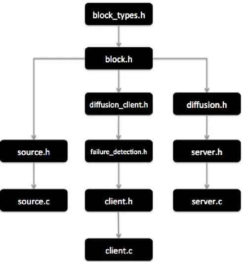
The idea behind creation and organization of different header files and source files is to separate the network level communication from the implementation of the hypercube structure. The organization of files is as follows (see Figure 3.5).
The header files for server and client (i.e. server.h and client.h) contain all declarations of functions and variables that are required by peers to communicate with each other. This involves functions to establish and close UDP connections, read from an entity (client, server or source), write to an entity (server or source) and some particular declarations and adaptations for the target architecture in order to finally make communication possible.
The header files with name starting with diffusion (i.e. diffusion.h and diffu-sion_client.h) basically contain all variables, data structures and functions neces-sary to create, run and manage the hypercube structure. File block.h contains the definition of data structure used for messages, that is Block. This is the basic
mes-Figure 3.5: File organization
sage format that is used for data as well as control packets. File named block.h also contains all the functions that are used to manipulate and display a block.
File named failure_detection.h contains the declaration and the implementation of all the functions and variables intended for our failure detection solution.
3.4.3 Data Structures
In this section we show the most important data structures used by a client. We thus ignore data structures used by source and server since they are not very significative for our purposes.
• id: this variable contains the current ID of the peer;
• primary_id: this variable contains the main id of the peer. It is worth pointing out that there is an important difference between primary_id and id. Indeed, id represents the current id used by the peer during a single retransmission phase. The reason why they can be different is that just after a replacement, some previous neighbors could be not up-to-date and still send packets to the replacing peer. In order to avoid losses or disruptions due to some delays in the delivery of updating packets, the replacement peer has to keep disseminating content also as he would do in the previous position. We will clarify this aspect in next sections;
• secondary_id: this variable contains the previous main id of the peer. If a peer has replaced another peer in the past, secondary_id is set to his previous id;
• dim, last, level: this variables respectively contain values of dimension, last level and level to which the peer belongs;
• pacsent[dim]: it is an array of dimension ’dim’ and contains information to know which data block number must be sent at each time slot. pacsent is computed by each peer by just looking at his identifier which has been assigned by the server. For example a peer with identifier 01010 will have pacsent = {1,3,3,1,1}. This means that data block sent at time slot 0 is 1, 1 at time slot 1, 3 at time slot 2, 3 at time slot 3 and 1 at time slot 4. It is worth noticing that data block number and time slot are always treated as modulo dim. as an example, if block number is 20 then it corresponds to 20 modulo 4 (i.e. dim -1) which is 0;
• pacr[dim]: it is an array of dimension ’dim’ and allows a peer to know in advance each data block it is going to receive at each time slot. We recall
that a peer can compute this information by just looking at his identifier. For example a peer with identifier 01010 will have pacr[ ] = {4,1,2,3,0}. By checking out values of pacr[ ], a peer can realize that at time slot 6 he is going to receive data block number 8 and at time slot 9 he is going to receive block number 9;
• times_sent[dim]: this structure is different from pacsent and pacr, from a . times_sent gives information regarding how many times a data block is suppose to be sent by a peer. For example, a peer with an identifier 00010, will send data block 1 five times and never sends all the other block (i.e. 0, 2, 3, 4). Thus for peer 00010, times_sent[ ] = {0,0,0,5,0}. Just to explain the difference between times_sent and the other data structures, we can look at the example we showed in the description of pacsent & pacr i.e. 01010. times_sent for this peer is {0,2,0,3,0} which means that this peer sends block 1 three times, data block 3 twice and never sends the other blocks;
• neighbour[dim]: in this array we store identifiers, and corresponding coordi-nates, of all hypercube neighbors of a given peer. It is worth noticing pointing out that in this data structure we store only formal neighbors, which are those neighbors that meet the rule we defined in the section 3.1. We recall that a hypercube neighbor’s identifier vary with identifier of given peer by only one bit. For peer 01010, the neighboring peer will be 01011, 01000, 01110, 00010 and 11010.
Before introducing the next data structure, a little background is required. As we mentioned before, we adopt a special strategy in order to adapt both the hypercube structure and dissemination rules in case the number of peers in the system is lower than the maximum allowed, in other words, when the hypercube is incomplete.
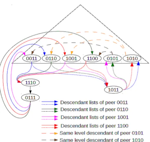
The only levels affected by this adaptation are the second-last and the last one. Peers in the last level are grouped in multiple descendant lists. Every descendant
Figure 3.6: An example of descendant list
list is associated to a different ancestor, who is a peer belonging to the second-last level. Once ancestors receive a block, they forward that block to the corresponding descendant list. Indeed, also descendant lists are built according to identifiers. Each ancestor needs to keep just the identity of the head of each descendant list, which is the peer with the lowest id. It is worth saying that, for stability reasons, descendant lists are maintained also by peers that do not belong to the last or second-last level. The main reason why we decided to do so is mainly due to the very likely event in which the number of levels change during the transmission. Indeed, in that case we would need to rebuild descendant lists, this task could take some time and generate delays, resulting in worse performance.
Data structures used for managing descendant lists are the following:
dimension holds descendant list associated with each bit position and second dimension holds details of peers in that list. As we can see in 3.6, peer 0011 has total four possible descendant lists out of which only two are not empty. Thus descendants[3][ ] and descendants[2][ ] are both empty. Instead, descen-dants[1][3] = details of {1110, 0111, 0110} and descendants[0][ 2] = details of {1011, 1010};
• ancestors[dim]: for peers in the last level, ancestors structure holds details of peers in second-last level that are supposed to send blocks to the head of the descendant list he belongs to. As we can see in 3.6, ancestors of peer 0111 are peer 0011, 0110, 1001 and 1100 as they send blocks to peer 1110, which is also the head of the descendant list to which he belongs;
• same_level_ancestors[dim]: this data structure helps peers at second-last level to hold details of the peer who are their ancestors but belong to the same level. As we can see in 3.6, same level ancestors of peer A = 0101 are 0110 and 1001 as both of them send blocks to descendant list of which peer A is the last descendant;
• same_level_last_descendant[dim]: this data structure contains, for each descendant list, a peer belonging to our same level, who is the next member of the ancestor chain for a given block descendant list. This structure can be used in two different ways during the transmission phase: the first one is to communicate to descendants the identity of the next ancestor to whom to retransmit when the block reaches the last peer, the second one is to send a block directly to him in case the corresponding descendant list is empty; • vote_list[ ], repair_list[ ]: these data structures allow to maintain a set
of peers, belonging to the last level, that could be potential replacements in case the current wants to leave the system. We will go into more detail in the section focused on management of arrival and departures;
• send_to_desc[] (secondary_send_to_desc[]): this data structure is maintained by every peer belonging to a level which is not the last one. In-deed, as we mentioned before, descendant lists are maintained even when it is not required, in order to be prepared in case the number of levels changes. However, this data structure is actually used by only peers in the second-last level and contains the identity of the first member of each descendant list. Instead, secondary_send_to_desc is used for retransmitting blocks received after a replacement and still pointing to our previous identifier;
• send_to_succ (secondary_send_to_succ): this variable contain coor-dinates of our successor in the descendant list. As for send_to_desc[], sec-ondary_send_to_succ is used only for blocks still pointing to our previous identifier;
• receive_from_succ: this variable contains coordinates of our predecessor in the descendant list;
• my_id_location: by checking the value of this variable, we know if we are the last peer in our descendant list or not. Because of historical reasons, the name of this variable does not match exactly its actual meaning;
• head_of_the_list: by checking the value of this variable, we know if we are the first peer in our descendant list or not;
• replacing: this is a special variable used only when we are replacing a peer who has been expelled from the system. If it set to 1 then the departure is not spontaneous (the departing peer has crashed or whatever), otherwise the departure is spontaneous (the departing peer has autonomously decided to leave the system);
• receive_from: each peer in the system stores the details of peer from whom he has just received a block. Even though it is declared as an array, currently
only the first position of receiver_from is being used. This information is used for several purposes such as replying to an explicit request from a given peer, etc.
• tableFrames[ ]: this array keeps track of which data blocks have been re-ceived by a peer. This structure helps to:
– ensure if all the data blocks are received by a peer or not, – find out the data blocks that have not been received,
– retransmit data blocks that a peer has received but one of its related peers did not.
• nbFrames: this variable stores the highest block number that has been re-ceived by a peer.
3.4.4 Data Structures for Failure Detection
In this section we explain the meaning of some special data structures used for failure detection purposes.
First of all, we need to point out that our solution is to piggyback information about blocks received or lost, by attaching it to standard data blocks.
In order to do so, we defined two new data types: typedef s t r u c t {
uint32_t concerningpeer ; uint32_t frompeer ;
uint32_t throughput [REPORT_WINDOW] ; uint32_t l o s s e s [REPORT_WINDOW] ; uint32_t nsent ;
s t r u c t timeval last_time_sent ; }
Report_History ; where
• concerningpeer and frompeer represent contain identifiers of two different peers,
• nsent is a counter where we store the number of reports received,
• throughput[] and losses[] contain a sequence of values which are used by the peer in order to decide if concerningpeer is not cooperating sufficiently. If so, the peer starts the procedure to expel concerningpeer from the system, • last_time_sent store the timestamp of the last time a given report has been
sent by the peer,
• REPORT_WINDOW is a constant which defines how many reports can be stored. Of course, reports are stored according to their chronological or-der, this means that if the current size of the report window exceeds RE-PORT_WINDOW, the oldest report is discarded,
and typedef s t r u c t { double_t throughput ; double_t l o s s e s ; C l i e n t c l i e n t ; uint32_t n r e p o r t s ; } Average_Report ; where
• throughput and losses store the averaged values of throughput and losses piggybacked with blocks,
• client is a data structure which contains information about the client associ-ated to that report,
• nreports is a counter that keeps count of how many reports have been sent.
Data structures used for managing reports are the following:
• leader_reports[dim][dim]: this data structure is maintained only by those peers that are the designated leader of one or more peers. It is worth remarking that the designated leader of a given peer is always one of his hypercube neighbors. It is a bidimensional array because the first dimension is intended to individuate reports concerning a given peer, and the second dimension is intended to individuate reports sent by a given peer;
• route_reports[dim][dim]: this data structure is maintained by every peer. The aim of this structure is to store reports piggybacked with blocks received by a given peer. In this case, the meaning of the two dimensions is inverted: the first dimension is intended to individuate reports sent by a given peer, and the second dimension is intended to individuate reports concerning a given peer;
• average_reports[dim][dim]: this data structure is maintained only by lead-ers. The aim of this structure is to compute mean throughput and losses achieved by several peers from a given peer. This way, a leader is able to correctly detect a failed peer and expel him from the system. We recall that a peer is considered as failed when either he crashed or the level of cooperation that he is offering is not sufficient anymore.
We will go into more detail in the section focused on failure detection, where we will extensively explain every detail on our solution for failure detection and recovery.
3.4.5 UDP Packet Format
As we mentioned in previous sections, we use UDP as transport protocol. More precisely, we defined a custom UDP packet format in order to transmit both data blocks and info blocks. We recall that info blocks differ from data blocks because they do not contain any piece of content, they are used only for exchanging infor-mation required to build or maintain the hypercube structure. We will give a wide explanation of all existing block types and their use in the next section.
In order to treat our custom UDP packet format, we defined a C data structure, which is composed by the following fields:
• uint32_t type: a unique identifier for each block type;
• uint32_t blknb: a unique identifier for each data block. It is incremented by the source;
• uint32_t trmnb: number of times each data block has been retransmitted within the hypercube structure;
• uint32_t id: the identifier of the sender;
• uint32_t dim: current dimension of the hypercube structure. Possibly, the system should be able to dynamically vary the dimension according to current needs. Currently the system does not manage yet this kind of event but, ideally, this operation should not be very complex;
• uint32_t last: current last level of the hypercube;
• uint32_t nb_neigh: total number of peers in cl list. That list is used for several block types. Its aim is to attach to any block (not only the ones containing data) a set of peers, and their respective coordinates, which have to be used by the receiving peer;
• uint32_t c_anc: in origin this field was used for storing the number of ancestors in the cl list. Currently, it is used to for storing sender’s id;
• uint32_t c_desc: in origin this field was used for storing the number of descendants in the cl list. Currently, it is used for storing receiver’s id;
• uint32_t ack: this fields is is used by sender to store the number of the last received block. In other words, a sender uses this fields to tell the receiver the number of the last block received from him. This way, each neighbor can figure out if a packet was lost and, if necessary, resend it;
• Client cl[MAX_DIM]: as we mentioned before, this array contains a set of clients and their coordinates. It is used for every block type that needs to communicate to the receiver one or more coordinates of one or more peers; • Report_network reports[2]: this array contains two data structures used
in the context of failure detection. We will analyzing closely this data structure in the section focused on our solution for failure detection;
• StreamPackets streamPackets: this field is the one that actually contains data. More precisely, this fields encapsulates UDP/RTP packets sent by the stream source by wrapping them with fields we just showed. We recall that the stream source is not the same process that operates as source for our P2P system. Indeed, the stream source just generates the stream to disseminate over the system, instead the the source process is the process in charge of encapsulating the stream packets in our custom UDP block format.
Data structures used for failure detection will be studied more deeply in next sec-tions. Instead, we now show the fields that compose StreamPackets data structure: • size_t sizes[1]: this array contains the size of each UDP/RTP packet
• char data[10000]: as we its name suggests, this array of bytes is the fields that actually encapsulates packets generated by the stream source. It is defined as an array of chars because this is the best way to declare a field as a sequence of bytes. Of course, 10000 bytes is just the maximum allowed size of the encapsulated content. Indeed, the size of packet can vary depending on the size of the encapsulated content. This means that there is no waste of bandwidth. It is worth pointing out that our UDP block format can potentially encapsulate even more than one single packet. This can be achieved by just increasing the size of sizes array and put every packet one after another in data array.
There are two important things that are worth pointing out:
• any significant property of the hypercube structure is piggybacked with data blocks;
• the total size of each data block does not exceed the recommended UDP mes-sage size, which is less than 1500 bytes. The choice of this value depends on the maximum allowed size of a IP datagram. Technically, the maximum UDP message size is 65507, but we want to avoid the unfortunate event in which the entire UDP datagram is considered lost or corrupted because of a single lost IP datagram. This means that the safest size of a UDP message is equal to the maximum IP payload size.
3.4.6 Block Types
In this section we draw up the list of all block types currently used in our system.
TYPE SENDER RECEIVER PROCESSING NOTES
1a Any peer who wants to join the system
Server Server returns a unique identifier for the new peer
TYPE SENDER RECEIVER PROCESSING NOTES
1b Server A peer who has sent a joining request and is waiting for an identifier
The cl list attached to this block contains coordinates of neighbors, ancestors, descendants, same level descendants and same level ancestors. The new peer also uses his identifier to compute identifiers of neighbors in the hypercube and populate data
structures.
Receiving peer sends block type 2 to all the peers in the cl list and block type 25 to ancestor[0] in order to join his descendant list.
11 Any peers who joins the system
Server Server marks the id of the sender as assigned.
2 Any peer Any peer who is related to the sender (neighbor, descendant, ancestor, successor or predecessor in the descendant list, etc.)
Receiving peer updates coordinates corresponding to sender.
TYPE SENDER RECEIVER PROCESSING NOTES 12 Any peer in a descendant list Any peer in a descendant list, except the head of the list
receiving peer updates coordinates of ancestor[0].
When a peer receives an update (block type 2) from ancestor[0], he updates also all the members of his descendant list.
4 A peer, belonging to the last level, who is leaving the system Server and predecessor in the descendant list
Server marks sender’s id as not assigned anymore, so it is available. Predecessor updates his successor, if any.
For this block type, server uses the cl list in order to store coordinates of his current successor. If he is the last peer in the descendant list, the cl list is empty.
14 A peer who is the head of the list and is leaving the system or changing position (re-placement). Every ancestor of the leaving peer.
Ancestors that receive this block, update
send_to_desc data structure.
TYPE SENDER RECEIVER PROCESSING NOTES 24 A peer (not head of the list) who is leaving the system or changing position.
Successor Receiving peer updates coordinates of his predecessor in the descendant list. 34 A head of the list who is leaving the system or changing position.
Successor Receiving peer becomes the new head of the list.
For this block type, cl list is used for storing
coordinates of ancestors. 15 A head of the list who is leaving the system or changing position.
Ancestors Ancestors update send_to_desc data structure.
TYPE SENDER RECEIVER PROCESSING NOTES 25 A peer who wants to join a descendant list. He could be a peer who just joined the system or a replacement.
Ancestor[0] Ancestor[0] retrieves the descendant list to which joining peer is supposed to belong. After that, he checks if the descendant list is empty. If so, he sends a block type 16 to the sender, otherwise he sends a block type 6. 6 Any peer in a descendant list. Any peer in a descendant list.
Every peer that receives this block type checks if he has a successor or if
successor’s id is greater or equal than joining peer’s id. If so, he updates his successor, otherwise he just forwards the block.
TYPE SENDER RECEIVER PROCESSING NOTES
16 Ancestor[0] New head of the list.
After receiving a block type 25, ancestor[0] checks if the new peer will be the head of the list. If so, he sends to him a block type 16. We recall that peers are
ordered by their identifier (from the lowest to the highest), this means that even if a descendant list is not empty, a joining peer can become head of the list. 46 A peer in a descendant list. A peer in the same descendant list.
A peer that just joined a descendant list, sends this block type to his successor in order to make him aware of his presence.
TYPE SENDER RECEIVER PROCESSING NOTES
8a A departing peer
A peer belonging to the last level who has been chosen as replacement for the departing peer.
The departing peer chooses a replacement from his repair_list and sends to him a replacement request by attaching to the block coordinates of his
neighbors. We recall that neighbors mean not only hypercube neighbors but also all those peers with whom the peers
communicates, such as descendants, ancestors, etc.
8b A replacement who has taken the place of a departing peer
Server If a candidate for
replacement has taken the place of a departing peer, he sends a special block to the server in order to make him aware of new
coordinates corresponding to a given identifier.
TYPE SENDER RECEIVER PROCESSING NOTES 18 A replacement candidate who has accepted a replacement request Departing peer or Server
The aim of this block type is to send a positive
acknowledgement to the departing peer. If a departing receives this block he can safely leave the system. In case of a non-spontaneous departure, the replacement procedure is started by the server, so it is the server that receives the acknowledgement.
This block type shows the reason why each peer maintains a repair list which is a set of peers belonging to the last level. Indeed, if a peer refuses to replace a peer who is going to depart, the departing peer resends the same request to the next peer in repair_list. If repair_list is empty or all the peers refused the replacement request, the departing peers sends a block type 88 to the server.
TYPE SENDER RECEIVER PROCESSING NOTES 28 A replacement candidate who has refused a replacement request Departing peer or Server
The aim of this block type is to send a negative acknowledgement to the departing peer. If a departing receives this block he has to choose a new replacement before leaving the system. As for positive acknowledgements, also the server can receive this block type.
88 A departing peer who has no available peer in his repair list
Server Server builds a set of potential candidates for replacement by picking some peers from the last level. 102 A leader that detects a non-collaborative peers and decides to expel him from the system
Server Server acts as a departing peer would do. So it creates a block and attaches to it the set of neighbors of the departing peer.
The only difference
between the cl list of block type 81 and the one of block type 8 is the presence of coordinates of successor peer. Since departing peer has failed, replacement has to take his place but he needs to know coordinates of his successor. Clearly, server is the only entity
TYPE SENDER RECEIVER PROCESSING NOTES
81 Server A peer
belonging to the last level who has been chosen as replacement for the departing peer.
The peer chosen as
candidate for replacement acts exactly as for block type 8.
9 Departed peer
Neighbor of departed peer
It can happen that one or more neighbors of a departed peer are not aware of his departure due to some lost blocks. The departed thus stays alive for a while in order to detect if all his neighbors are aware of his departure. If not, he sends this special update block.
101 Server Any peer By receiving this block peer a peer is asked to safely leave the system.
This block type is used for simulations in order to simulate spontaneous departures.
TYPE SENDER RECEIVER PROCESSING NOTES
0 Server and peers
Any peer Block type 0 is used only for data blocks, that are those blocks that actually contain content to be played.
As we can see, a pretty large set of block types is currently used. This way we can easily understand the behavior of peers by just looking at block types sent and received. Indeed, this choice helped us also during the debugging and testing phase.
3.5 UDP Encapsulation/Decapsulation and
Proxy-like Behavior
Most of streaming P2P systems currently in production are coupled to a specific video format or communication protocol. Instead, our system is able to deal with any format and protocol. The only assumption we make is that the communication protocol is an extension or specialization of UDP, which is an acceptable assumption since several streaming or real-time systems use UDP as protocol.
The mechanism we used in order to achieve so, is UDP encapsulation/decapsula-tion. The first component of the transmission chain is the source process, which can potentially receive content from any kind of multimedia source. The source process encapsulates each UDP packet generated by the multimedia source into a custom UDP packet format and transmits it over the system. Each peer can decode and reproduce the original stream by just decapsulating the UDP packet encapsulated by the source process at the beginning of the transmission. Once a peer decapsulates
Figure 3.7: System Architecture
From this brief description we can deduce that our system works more or less like a proxy: it creates a bridge between the source of a media stream and several clients who want to reproduce that stream. Indeed, the last component of the transmission chain, in other words the software that reproduces the stream, is not aware of the dissemination strategy adopted by peers.
Chapter 4
Population Variation
In this section we will show how our system handles population variation, that is departures and arrivals. As we all know, in any system for video streaming, no matter to which taxonomy it belongs, population tends toward fast variation and high dynamicity. This means that any system has to efficiently manage departures and arrivals, even if they are grouped. Grouped means that there are several arrivals and departures simultaneously. This issue is highly amplified in a structured P2P system, where two of the most important requirement are stability and consistency.
4.1 Departures
In this section we deeply study the behavior of the system in case of a departure. In this section we assume that departures are strictly spontaneous, instead in the next section we will study how forced departures due to the presence of a non-collaborative peer are managed.
Every departure starts from a peer that decides to leave the system. As we mentioned in previous sections, before leaving the system a peer has to choose a replacement from his repair list. The replacement must be one of peers in the last level, this allows us to minimize changes required in the structure and the amount of signaling blocks to be exchanged.
Before showing in detail our departure strategy, it is worth pointing out that it is used only for non-last levels. Indeed, departing peers from last level do not need any replacement, they just have to safely unjoin their descendant list.
We now explain the departure procedure by showing an algorithm for both de-parting peer and replacement peer.
Departing peer
1 : I f r e p a i r l i s t i s empty then
Ask s e r v e r f o r a r e p a i r l i s t by sending a 88 block Wait f o r an answer from the s e r v e r and populate your
r e p a i r l i s t
2 : Pick a replacement from the r e p a i r l i s t and send to him a 8 block
3 : Wait f o r an answer from the p o t e n t i a l replacement 4 : I f answer i s p o s i t i v e then
unjoin descendant l i s t Else
I f r e p a i r l i s t i s s t i l l non empty then Go to step 2
Else
Go to step 1
5 : do not l e a v e system as long as t h e r e are some pe e rs that are not up to date
Replacement peer
I f peer i s in l a s t l e v e l and did not accept yet any replacement r e q u e s t then
send a 18 block ( p o s i t i v e ack ) unjoin descendant l i s t
Figure 4.1: Spontaneous Departure: Phase 1 previo us ID
send a 8 block to s e r v e r in order to update c o o r d i n a t e s
r e s e t and i n i t i a l i z e a l l data s t r u c t u r e s send a block type 2 to a l l new neighbors j o i n new descendant l i s t
Else
send a 28 block ( n egat ive ack )
As we can see our strategy to handle departure requires just a few changes in the hypercube structure. We recall that the only levels affected by a departure are the last one and the one in which departing peer is, so there is no domino-effect. This characteristic of our strategy allows to keep the number of blocks to exchange between peers as low as possible, resulting in good performance. Indeed, in a video streaming service, an user expects the system to be as stable as possible, regardless of what happens in background during the playback phase.
Figure 4.2: Spontaneous Departure: Phase 2
immediately the system but keeps active for a while, in order to check if every neighbor is aware of the arrival of the replacement. Indeed, if departed peer still receives some blocks after leaving the system, he sends to sender a 9 block containing coordinates of replacement. This way we can safely handle massive and grouped departures and keep the structure stable and consistent. We also avoid to lose blocks during replacement procedures since peers that are not up-to-date yet could still retransmit blocks to departed peer, in that case departed peer takes care of retransmitting received blocks.
4.2 Arrivals
Even arrivals are managed in a way that is intended to be efficient and minimize the number of changes in the hypercube structure. We recall that a new peer is always assigned an identifier belonging to last level.
The algorithm executed by a peer during the arrival phase can be summarized as follows:
![Figure 3.3: An example of descendant list in last level [9, 10, 7] or the solution results in much longer delays [2].](https://thumb-eu.123doks.com/thumbv2/123dokorg/7482569.103151/28.892.181.713.133.362/figure-example-descendant-level-solution-results-longer-delays.webp)