This content has been downloaded from IOPscience. Please scroll down to see the full text.
Download details:
IP Address: 192.167.23.210
This content was downloaded on 17/11/2015 at 10:34
Please note that terms and conditions apply.
Analysis of the temperatures measured in very thick and insulating roofs in the vicinity of a
chimney
View the table of contents for this issue, or go to the journal homepage for more 2015 J. Phys.: Conf. Ser. 655 012019
(http://iopscience.iop.org/1742-6596/655/1/012019)
Analysis of the temperatures measured in very thick and
insulating roofs in the vicinity of a chimney
M Neri1, D Luscietti2, S Bani3, A Fiorentino2 and M Pilotelli2
1,2
University of Brescia, via Branze, Brescia, Italy
3
Associazione ANFUS, via della Cascina Pontevica, Folzano, Brescia, Italy
E-mail: [email protected]
Abstract. Chimneys convey exhaust gas produced in domestic heat appliances to the external
environment and to do this they have to pass through elements such as roofs and floors. If these elements are made up of flammable materials the fire hazard may occur. In some European countries the number of roof fire is very high and they affect also certified chimneys, that is, tested following the prescription of the related standards. The aim of this paper is to highlight that the certification procedure does not allow to test chimneys in the worst condition, therefore, chimney installed following the manufacturer prescriptions may in some cases cause the overheating and subsequent roof fire. To do this, experimental tests have been performed for measuring the temperature on roofs in the vicinity of a certified chimney. The results show that the certification procedure should be revised.
1. Introduction
The overheating of flammable materials due to the presence of a chimney has been analyzed in the past for determining the temperature of the outer surface of the chimney [1-4] and to define safety distances for preventing the burning of structural elements [4-7]. Nowadays, despite of the chimney heat performances are tested following the EN ISO 1859 standard [8], the number of roof fires in some European countries do to the presence of a chimney is very high [9-14].
The standard [8] prescribes the heat stress test and the thermal shock test by means of which the distance to be respected between chimney and flammable materials is determined. The heat stress test, analyzed in this paper, consists in installing the chimney to be certified in a structure following the manufacturer prescriptions, in producing exhaust gas at a predetermined temperature and in measuring the temperatures on the test structure until the achievement of the final test condition. The finale test condition is defined as an increase of the temperature on the test structure lower than 2°C in 30 minutes. If the measured temperatures on the flammable materials do not exceed 85°C, the chimney is certified and a label is attached on it. The label reports the permitted exhaust gas temperature and the required distance from flammable materials, but no information is given about the way of sealing the eventual clearance between chimney and roof. The test structure is composed of two walls at right angle of thermal resistance equal to 2.73 m2K/W and two floors positioned at different height. The floors are made up of three layers: a lower wooden layer 12 mm thick, an upper wooden layer 20 mm thick and an intermediate layer of mineral wool that is 200 mm thick for the lower floor and 100 mm thick for the upper floor.
Recent studies investigated the differences between the conditions in the certification procedure prescribed by the standard [8] and those in real installations, but all of them analyzed configurations in 33rd UIT (Italian Union of Thermo-fluid-dynamics) Heat Transfer Conference IOP Publishing Journal of Physics: Conference Series 655 (2015) 012019 doi:10.1088/1742-6596/655/1/012019
which a chimney was installed in the corner of a roof and near two walls. These studies highlighted that in real installations the condition can be much more critical. Real roofs can be thicker than the floors prescribed by the standard [8], for example in the countries of the north of Europe their thickness can reach 1000 mm. In the label no information is given about how to seal the space between chimney and roof (clearance); then, it may be sealed in a different way with respect to that adopted in the certification procedure. For example, some chimney producers prescribe to test chimneys with open clearance, but this installation can not be performed in real installations because the entering of atmospheric agents must be prevented. In energy-saving buildings the clearance is usually filled with insulating material to avoid condensation and thermal bridges and this represents a very dangerous practice. The influence of the clearance sealing mode and the roof characteristics on the temperature in the roof was experimentally shown by [15]: this study analyzed the configuration prescribed by the standard [8] and it demonstrated the importance to specify in the label reported on the chimney the clearance sealing mode adopted in the certification. Weaknesses related to the way of measuring the exhaust gas temperature in the certification procedure were experimentally highlighted: Leppänen et al. [16] showed the flue gas temperatures of fireplaces is higher than temperature indicated in CE marking [16], Inha et al. [17] showed that for light-weight metal chimneys one fire cause is the high flue gas temperatures of sauna stoves. In [15] it was shown that the temperatures measured on flammable materials are related to a lower exhaust gas temperature than that used to define the class temperature of the chimney, and the final test condition does not allow to measure the stationary temperature on flammable materials. Experiments were performed to assess the influence of the smouldering combustion of the binder of rockwool used to manufacture chimneys [18]: this phenomenon determines an escalation of temperature that could cause the ignition of flammable materials in the vicinity of the chimney. In [19] a 3D numerical model was designed to reproduce the condition of the heat stress test, and a lumped element model for estimating the stationary temperature from the temperature-time curves measured in the heat stress test was also proposed.
The aim of this paper is to highlight, by means of experimental tests, that the heat stress test proposed by the standard [8] does not allow to test chimneys in the worst conditions. To do this, a certified chimney has been installed at the center of three roofs following the manufacturer prescriptions. By installing a chimney at the center of a roof, it is not affected by the presence of the walls that, having a lower thermal resistance than the roofs, facilitate the heat dispersion. One roof is representative of the more insulating roof prescribed by the standard [8], while the other two are representative of roofs in energy-saving buildings. The clearance between the chimney and the roofs has been sealed in four different ways to reproduce the conditions that may occur in real installations, that is, open, sealed with metal sheets, sealed with insulating panels, and filled with insulating material. Despite the exhaust gas temperature has been kept lower than that for which the chimney is certified, in the majority of the tests, temperature of flammable materials has been higher than 85°C. The results of these have confirmed that one possible cause of roof fires is a weak certification procedure.
2. Materials and methods
The tests described in this paper consisted in the following steps: installation of a certified chimney in the center of a roof following the scheme in Figure 1 ((a) and (b)), production of exhaust gas at a predetermined temperature Tch, measurement of the temperatures in the roof at the positions indicated
in Figure 1 ((b) and (c)).
33rd UIT (Italian Union of Thermo-fluid-dynamics) Heat Transfer Conference IOP Publishing Journal of Physics: Conference Series 655 (2015) 012019 doi:10.1088/1742-6596/655/1/012019
Figure 1. Test structure: a) front view, b) top view, c) thermocouples positioning. Letters A,
B, C and D indicates the lines on which the thermocouples were posed. Dimensions are in millimeters.
2.1 Test structure
The test structure is represented in Figure 1 (a) and it consists of a roof, a chimney and a heat generator. The chimney was installed at the center of the roof, and connected to the heat generator by means of a flue pipe, and an additional one was also installed to convey the exhaust gas far from the test structure. The chimney used in the test is certified T600 when it is installed 20 mm far from flammable materials. This means that during the certification procedure the exhaust gas temperature was 700°C and the maximum temperature measured on flammable materials did not exceed 85°C. In our tests, the chimney was installed respecting the manufacturer prescriptions reported in the label attached on it, that is, 20 mm from the roof and for safety reasons, the exhaust gas temperature was maintained at 500°C instead of 700°C.
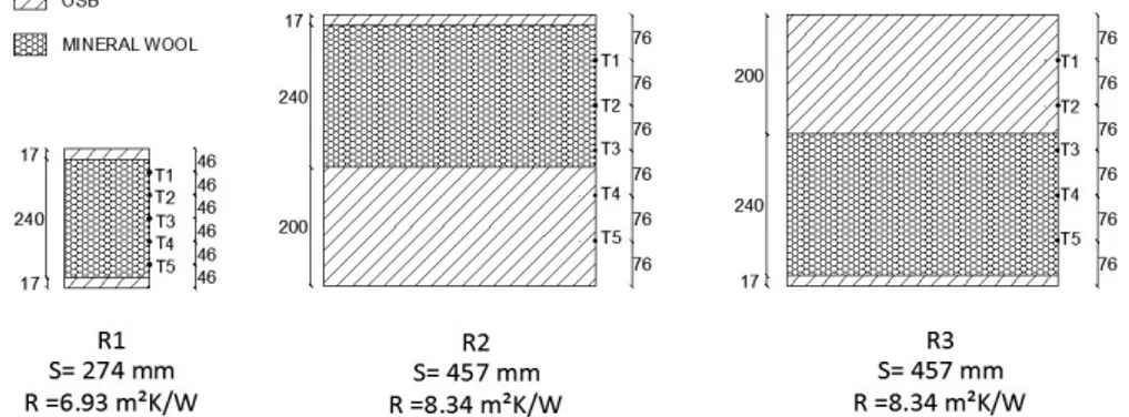
The roofs in which the chimney was installed are shown in Figure 2. Roof R1 is similar to the lower floor prescribed by the standard [8] but it is a little thicker and more insulating, roofs R2 and R3 have same thickness and same thermal resistance but different layers position and are representative of roofs in energy-saving buildings. By performing tests on roof R2 and R3 has allowed to understand if the layers position affects the maximum temperature on the roof. The chimney was installed 20 mm far from the roof as prescribed by the manufacturer and the clearance was sealed in four ways that are represented in Figure 3. The clearance was left open (op), sealed by means of metal sheets (ms), sealed with insulating materials (ad) and filled with insulating materials (fi). The sealing with metal sheet (ms) allowed air movement in the clearance and heat transfer through the sealing, the sealing with insulating panels (ad) allowed air movement in the clearance but prevented heat transfer through the sealing and it has been realized to approach an adiabatic sealing. Finally, the filling (fi) of the clearance reproduced the installation usually adopted in energy-saving buildings. Each roof was tested with each sealing mode, for a total of 12 tests, which are reported in Table 1. The tests are identified by acronyms: the first two letters represent the roof and the last two the clearance sealing mode. The standard [8] prescribes to stop the test when the increase in temperature is lower than 2°C in 30 minutes, or after 8 hours. However, it was not possible to reach this condition in all the tests as specified in Table 1.
33rd UIT (Italian Union of Thermo-fluid-dynamics) Heat Transfer Conference IOP Publishing Journal of Physics: Conference Series 655 (2015) 012019 doi:10.1088/1742-6596/655/1/012019
Figure 2. Tested roofs. S represents the thickness and R the thermal resistance of the
roof. T1, T2, T3, T4 and T5 indicate the positions where temperatures have been measured. Dimensions are in millimetres.
Figure 3. Tested clearance sealing mode: a) open (op), b) sealed with metal sheet
(ms), c) sealed with insulating material (ad), d) filled with insulating material (fi).
Table 1. Experimental tests and their characteristics. The acronym a.a.t. means
aluminum adhesive tape.
33rd UIT (Italian Union of Thermo-fluid-dynamics) Heat Transfer Conference IOP Publishing Journal of Physics: Conference Series 655 (2015) 012019 doi:10.1088/1742-6596/655/1/012019
2.2. Temperatures measurement and elaboration
Temperatures were measured by means of 24 thermocouples of type K and two DAQ NI 9213 connected to a PC. K thermocouples have an uncertainty of ±2.8°C for temperatures ranging between 0°C and 350°C and of ±0.75\% for temperatures ranging between 350°C and 1260°C. The uncertainty of the DaQ is ±0.02°C. Temperatures were recorded every 10 seconds. Exhaust gas temperatures were measured at the chimney inlet (Tgas2) and at the chimney outlet (Tgas3) as shown in Figure 1, and also
the environment temperature (Tenv) was measured. Flammable materials temperatures were measured
according to the schemes in Figures 1 and 2. Thermocouples were positioned vertically and equidistantly and then they were spaced 4.6 cm in tests performed on Roof 1 and 7.6 cm in tests performed on Roof 2 and Roof 3. The tests were stopped as indicated in Table 1 and for each thermocouple, the final temperature on the roof (Tend) was determined as average of the temperatures
recorded in the last five minutes of the test. In this way, it was possible to filter final results from instantaneous fluctuations.
Since the conditions in the clearance can be considered axial-symmetrical, a unique temperature value (calculated as average of them) was determined for the four corresponding thermocouples (positioned at the same height). Five temperatures were calculated: for example, from thermocouples A1, B1, C1 and D1, a value T1 was determined. Due to the length of their duration, it was not possible to repeat the tests but, by averaging four values, it was possible to obtain a rough estimate of their internal variability due to the installation mode of the chimney and of the thermocouples. The temperature inside the chimney (Tch) in correspondence to the roof was calculated as Tch=(Tgas2+Tgas3)/2.
2.3. Uncertainty and internal variability
Uncertainty of temperatures was determined as the sum of the uncertainty related to the measuring instruments and that related to the data elaboration. The uncertainty is ±2.9°C for gas temperatures (Tgas2, Tgas3) and the environment temperature (Tenv), and the uncertainty of the flammable materials
temperatures is 3.7°C. Final flammable materials temperatures have been determined as average of four values and the related variability as been determined as the difference between the maximum and the minimum values.
3. Results and discussion
The analysis has been done by comparing measured maximum temperatures, and comparing the temperature profiles measured on roofs R2 and R3.
3.1. Roof maximum temperatures
Figure 4 shows the maximum temperature measured in the tests. It can be noted that, despite the exhaust gas temperature was 200°C lower than in the certification procedure, in the majority of the tests, the maximum temperature exceeds the limit of 85°C. The only configuration that allows to respect the limit temperature is with open clearance (R1op, R2op and R3op) and for the others
configurations (R2ms, R2ad, R2fi, R3ms, R3ad, R3fi) the more insulating the clearance sealing mode, the
higher the temperature in the roof. In the test R2fi the measured maximum temperature is lower than
that measured in the test R2ad: this is due to the fact that R2fi test was interrupted at an instant farther
from the stationary condition with respect to R2ad. However, by estimating the stationary temperature
by means of the lumped element model proposed in [19], also for roof R2 the higher temperature has been reached in the case with filled clearance. In roof R3, the clearance has been sealed with aluminum adhesive tape in order to reduce air infiltration.
The fact that the measured temperatures are higher than 85°C can be due to three causes: the roofs used in this experimental campaign are thicker than those prescribed by the standard [8], the clearance has been closed in different ways than those adopted in the certification procedure (that it is unknown) and, moreover, installing the chimney at the center of a roof represents a worst condition than that 33rd UIT (Italian Union of Thermo-fluid-dynamics) Heat Transfer Conference IOP Publishing Journal of Physics: Conference Series 655 (2015) 012019 doi:10.1088/1742-6596/655/1/012019
occurs when the chimney is installed in the corner of it. However, the installations were performed following the indications reported in the label of the chimney. Then, it can be stated that the information reported in the label is not enough to ensure safety installations: information about how the clearance was sealed in the test procedure would allow chimney installers to reproduce the same conditions tested in the certification procedure.
It must be remarked that in last years, the thickness of the roofs has incremented so much that those prescribed by the standard [8] do not represent the worst condition that can occur in real installations.
Figure 4. Maximum temperatures measured in the experimental tests performed on roofs R1,
R2 and R3 with the four clearance sealing modes (open (op), sealed by means of metal sheets (ms), sealed with insulating panels (ad) and filled with insulating materials (fi)).
3.2. Roof layers position influence
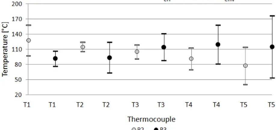
In order to understand whether the roofs layers position affects the position of the maximum temperature on roofs, temperature profiles measured on roofs R2 and R3 are reported in Figures 5, 6, 7 and 8. Roofs R2 and R3 have same thickness and thermal resistance but different layers position. Figure 5 shows the temperatures measured on the roofs when the clearance was left open. It can be noted that for this installation mode the mean temperatures are quite homogeneous but for the roof R3 they are affected by high variability. High variability can be attributed to the loss of the axial-symmetric condition due to environmental conditions (speed and direction of the wind), and the presence of the heat generator.
Figures 6 and 7 show the temperatures measured on roof R2 and R3 when the clearance was sealed by means of metal sheets (ms), and by means of insulating material (ad) respectively. It can be noted that with respect to the cases with open clearance (Figure 5) the temperatures are less homogeneous: in both cases the higher temperature have been measured on the insulating layer, that is, in the upper part of roof R2 and in the lower part of roof R3.
33rd UIT (Italian Union of Thermo-fluid-dynamics) Heat Transfer Conference IOP Publishing Journal of Physics: Conference Series 655 (2015) 012019 doi:10.1088/1742-6596/655/1/012019
Figure 5. Temperatures on roofs R2 and R3 measured with open clearance. T1, T2,
T3, T4 and T5 indicate the thermocouple positions, where T1 is the highest one.
Figure 6. Temperatures on roofs R2 and R3 measured with clearance sealed by
means of metal sheets. T1, T2, T3, T4 and T5 indicate the thermocouple positions, where T1 is the highest one.
Figure 7. Temperatures on roofs R2 and R3 measured with clearance sealed by
means of insulating panels. T1, T2, T3, T4 and T5 indicate the thermocouple positions, where T1 is the highest one.
33rd UIT (Italian Union of Thermo-fluid-dynamics) Heat Transfer Conference IOP Publishing Journal of Physics: Conference Series 655 (2015) 012019 doi:10.1088/1742-6596/655/1/012019
Figure 8. Temperatures on roofs R2 and R3 measured with clearance filled with
insulating material. T1, T2, T3, T4 and T5 indicate the thermocouple positions, where T1 is the highest one.
Figure 8 shows the temperatures measured when the clearance was filled with insulating material. Also in this case the maximum temperature was measured on the insulating layer, but the difference in temperature between the upper and the lower zones of the roofs is up to 100°C for roof R3 and it is higher than in the tests performed with other clearance sealing modes. When the clearance is sealed in the upper and lower parts the natural convection push hot air upward but the radiation tends to make uniform the horizontal heat flux in the vertical direction: on roof R2 the effect of the natural convection is accentuated by the presence of the insulating layer in the upper part. When the clearance is filled and only conduction takes place, the temperature increases on the more insulating layers. If thermocouples are installed following the standard [8] prescription - i.e. on the center line of the roof - the maximum temperature on flammable materials may not be measured.
3.3. Test final condition
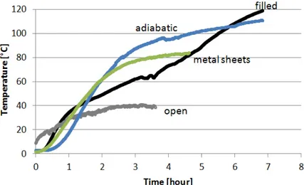
The standard [8] prescribes to stop the heat stress test when the increase in temperature on the test structure is less than 2°C in 30 minutes or after 8 hours. In Figure 9, four temperature time traces measured in tests with different clearance sealing modes are reported. All of them represent temperatures whose increase at the end of the test was less than 2°C in 30 minutes except for the thermocouple related to R1fi. It can be noted that if the tests had continued, the temperatures would
have increased. Then, the standard [8] should be modified in order to allow the stationary temperature detection. Since the achievement of the stationary temperature may take long time, the stationary temperature could be estimated by means of the lumped element model proposed by [19] applied to the temperatures measured during the heat stress test.
33rd UIT (Italian Union of Thermo-fluid-dynamics) Heat Transfer Conference IOP Publishing Journal of Physics: Conference Series 655 (2015) 012019 doi:10.1088/1742-6596/655/1/012019
Figure 9. Temperatures time traces measured in the tests performed on roof
R1 for different clearance sealing modes.
3.4. Influence of the thermophysical characteristics of the materials
By analyzing the temperatures in Figure 4 it can be noted that the roof characteristics do not affect strongly the maximum temperature in the roof, but rather the temperature distribution. Higher temperatures occur in the more insulating layer especially in the configurations with filled clearance. In the configurations with blocked air between chimney and roof (clearance sealed either with metal sheets or sealed with insulating panels) temperature distribution is more homogeneous because the effect of the layers arrangement is counterbalanced by radiation and convection.
In the configurations with air in the clearance, hot air rises because of natural convection and it heats the upper layer, even if radiation tends to homogenize the temperature distribution: then, if in the upper part of the roof there is a more conductive layer (in this case the wooden layer), the heat flow from the roof to the environment is facilitated because on the upper surface of the roof a greater convective heat transfer coefficient occurs.
In the clearance, the standard [8] prescribes a wooden lath 5 cm thick attached to the roof to contain the insulating material: the presence of the lath flatters the temperature distribution and, having a higher thermal conductivity with respect to that of the material in the roof, it acts as a thermal bridge and determines a lowering in temperature. Then, the presence of a conductive element in this position is suitable for keeping the temperature low, but at the same time, its presence in energy-saving buildings could represent a critical aspect.
By filling the clearance the increase in temperature is slower with respect to the configurations with air in the clearance, but it leads to higher temperature on flammable materials, as can be seen in Figure 9.
4. Conclusions
In this paper differences between the condition in the certification procedure prescribed by the standard [8] and the condition in real installations have been experimentally shown. The study focuses on the influence of the roof characteristics and the clearance sealing mode on the flammable materials in the vicinity of a chimney.
The tests have been performed by installing a certified chimney at the center of three roofs and the clearance between chimney and roof has been sealed in four ways. The configuration with a chimney installed at the center of a roof is more critical than the condition described in [8] because the walls of the test structure can act as a thermal bridge.
Despite the chimney has been installed following the manufacturer prescriptions reported on the label attached on it, and the exhaust gas temperature has been kept 200°C lower than that for which the 33rd UIT (Italian Union of Thermo-fluid-dynamics) Heat Transfer Conference IOP Publishing Journal of Physics: Conference Series 655 (2015) 012019 doi:10.1088/1742-6596/655/1/012019
chimney is certified, the temperature of flammable materials has exceeded the limit of 85°C in the majority of the tests. The limit temperature has been respected only in the configuration with open clearance. Since in real installations the clearance can not be left open, especially in roof penetrations, the certification procedure should not be performed with open clearance. In any case, the clearance sealing mode adopted in the certification should be specified in the label, as was already suggested for the installations in the test structure by [15]. Since higher temperatures have been measured in roofs representative of roofs in energy saving buildings in which the clearance is usually filled with insulating materials, tests ad hoc should be performed for these configurations. The layers position in the roof affects the temperature distribution, and higher temperatures are measured on more insulating layers. Then, to detect the actual maximum temperature, thermocouples should be installed vertically instead of horizontally. Temperature-time curves measured in the tests have shown that the final test condition does not allow to reach stationary temperatures. Therefore, they should be estimated by means of the lumped element model described in [19] and compared with the maximum temperature at which materials can be exposed. By comparing temperatures measured in these tests with those measured in the tests performed in the test structure and reported in [15], it can be stated that installations at the center of a roof is more critical because for the same configuration higher temperatures have been measured when the chimney was at the center of the roof, despite the environment temperature was lower.
In conclusion, the position of the chimney in the roof strongly affects the flammable materials temperature and to test chimneys in favour of safety, the certification procedure should be modified and a new structure should be designed. In this new structure, the chimney should be installed at the center of a roof and enough far from the border of the roof in order to avoid edge effects.
Acknowledgments
This research has been done in collaboration with Centro Studi ANFUS (Associazione Nazionale Fumisti e Spazzacamini) of Brescia. We also thank Legno Camuna of Brescia (Italy) and Bolletta srl (Perugia).
References
[1] National Fire Protection Association (1984) Standard for Chimneys, Fireplaces, Vents and Solid Fuel Burning Appliances, NFPA 211, Quincy
[2] Voigt G Q 1933 Fire Hazard of Domestic Heating Installations, National Bureau of Standard 11 353-372
[3] Lawson D I, Fox L L and Webster C T 1952 The Heating of Panels by Flue Pipes, Fire Research Special Report Fire Protection Association
[4] National Bureau of Standards 1941-1945 Prefabricated Metal Chimneys, Fire Research Section, Unpublished Report to the Federal Public Housing Authority More references
[5] Peacock R D 1987 Wood Heating Safety Research: an Update, Fire Technology 292-312 [6] Lawson D I and Simms D L 1952 The ignition of wood by radiation Brit. J. Appl. Phys. 3
288-292
[7] Kline L M and Witte H 1959 Performance of type B gas vent for gas-fired appliance Bulletin of
research
[8] UNI EN 1859 2009 Camini - Camini metallici - Metodi di prova, UNI, Milano
[9] Buffo S and Dadone P N (2007) Studio Statistico Vigili del Fuoco di Brescia sulle Cause dell'Incendio Tetto, Vigili del Fuco di Brescia, Brescia (in Italian)
[10] International Partnership for the Investigation of Fires Explosions and Other Major Incidents 33rd UIT (Italian Union of Thermo-fluid-dynamics) Heat Transfer Conference IOP Publishing Journal of Physics: Conference Series 655 (2015) 012019 doi:10.1088/1742-6596/655/1/012019
www.burgoynes.com, Accessed 21 July 2015
[11] Dadone P N 2009 Analisi 00. Casi Verificatisi sul Territorio della Provincia di Brescia e Statistica delle Cause, Incendi tetto e Canne Fumarie Proceeding Conference, Brescia (in Italian)
[12] Leppänen P 2010 Fire Safety of Metal Chimneys. Master's Thesis. Tampere University of Technology, Department of Civil Engineering, p 51 (in Finnish)
[13] Hakala V M 2013 Fire Investigations, Thematic Investigation 3: Chimney and Fireplace as Causes of Fire, 14 (in Finnish)
[14] Ministry of the Environment of Finland 2011 Finnish Concern on Fire Safety Risk Due to CE Marking of Appliances Fired by Solid Fuel and Chimney Products
[15] Neri M, Luscietti D, Fiorentino A and Pilotelli M 2015 Experimental Analysis of Chimneys in Wooden Roofs, Fire Technology DOI 10.1007/s10694-015-0525-7.
[16] Leppänen P, Inha T and Pentti M 2015 An Experimental Study on the Effect of Design Flue Gas Temperature on the Fire Safety of Chimneys, Fire Technology, p 847-866
[17] Inha T, Leppänen P, Peltomäki M and Pentti M 2011 Fire Safety of Light-weight Metal Chimneys. Tampere University of Technology, Department of Civil Engineering. Research report no. PALO 1950/2011 (in Finnish)
[18] Leppänen P, Neri M and Mäkinen J 2015 Heat release caused by the smouldering combustion of the binder of rockwool, Rakenteiden Mekaniikka (Journal of Structural Mechanics) 48, No 1 2015 68-82
[19] Neri M, Luscietti D, Bani S, Fiorentino A and Pilotelli M 2015 Chimneys in Wooden Roofs: a 3D Steady Numerical Model for the Prediction of the Temperatures, Conf. ASME-ATI-UIT, Napoli
33rd UIT (Italian Union of Thermo-fluid-dynamics) Heat Transfer Conference IOP Publishing Journal of Physics: Conference Series 655 (2015) 012019 doi:10.1088/1742-6596/655/1/012019