RASD 20
11 International Conference 1-3 July 2013 Pisa th3
EVALUATING THE SEISMIC EFFECTS ON LIFTING EQUIPMENT
L.Solazzi
Dipertimento di Ingegneria Meccanica e Industriale Università degli Studi di Brescia
Via Branze 38, 25123 Brescia, Italy E-mail: [email protected]
Keywords: earthquake, lifting equipment, crane, steel structure. ABSTRACT
The purpose of this paper is to assess the dynamic behaviour of various lifting equipment (different types of cranes, elevating work platform, etc.) subjected to seismic actions, evaluating how these actions can both generate failures and affect the structural behaviour of the machine. The work is developed starting from the design of the different machines of interest (according to some classical standards and specific performance like working load, lifting speed, working area, etc.), determining their geometry. Subsequently are applied the characteristic load spectra to the structures, related to the magnitude of earthquake; the final step consist in the structural analysis of the machines, computing their maximum stresses, displacements and natural frequencies, using different finite element codes. The results show that the first natural frequencies of the structures are very low and consequently the effects of the seismic action, in general, are not dangerous. Otherwise it is important to underline that the maximum stress induced by the earthquake is detectable in different position in the lifting equipment respect to maximum stress position in the normal loading operations, therefore seismic analyses are indispensable for study these parts of machines.
1. INTRODUCTION
Lifting equipment, composed by reticular steel structures, are characterized by very big size, extremely evident in portal cranes. The design of these machines is normally performed by different standards codes, like the European Standards, which do not consider the earthquake effects on the cranes: the main actions considered for the crane design are the dead load, the dynamical effects induced moving the load or the crane, the wind action (allowing different intensity limits), etc., but these load conditions (defined by the standard codes) never consider the seismic actions.
This paper wants to study the dynamic behavior of these machines and evaluate how dangerous are seismic actions for the structures, if compared with the actions induced by normal loading operations.
2. DEFINITION OF THE EARTHQUAKE ACTIONS AND NUMERICAL METODOLOGY
The actions induced by the earthquake were studied using the Italian Technical Standard 2008. This standard shows a similar procedure used in the Eurocode 8.
Figure 1. Trends of the load spectra of the seismic actions applied to the lifting equipment.
Figure 1 shows three different types of load spectra. In particular, the differences between the spectra were related to the “peak ground acceleration (PGA)”, which corresponds to the maximum acceleration of the ground induced by the earthquake. These values correspond to very high earthquake intensities, in other words more over the maximum detectable value of the Mercalli scale (corresponding to the most violent detected earthquake) or equal to level 6 (superior) of the Shindo scale. The motivation of this choice is based on the fact that this work wants to study the mechanical behavior of lifting equipment exposed to very high intensity earthquakes, correlated with the probability that such an event will occur during the useful life of the designed crane.
The procedure for FEM analyses are based on the superposition of the individual modal responses. In synthesis, after analyzed the response of the structure for the individual modes of vibration, it is necessary to combine the results to obtain the maximum displacement, or stress, acting on the structures. There are some numerical aspects necessary for a correct applications of this technique, using for example the methodology for combination of the results, like SRSS (or square root of the sum of the squares); the most important aspect is the number of the frequencies considered in the analyses, which must show a sum of percentage of mass participation factor more than 95%.
3. THE DIFFERENT TYPES OF LIFTING EQUIPMENT
Five different types of lifting equipment were analysed in order to evaluate the earthquake actions on their most important structural parts. Four of these machines are cranes; the last is an elevating work platform.
The work was developed by different steps. The first regards the preliminary design of the machines using the specific standards, like the European ones. The next step consists in the realization of the CAD model of the machines, necessary to perform the FEM analyses. The target of the last phase is to understand the mechanical behaviour of the component subjected to the classical actions (like dead load, pay load and its position, dynamical load induced by
the movement of the load, wind action, and loads by the erection of the structures, etc.), with the aim of evaluating both the safety factor and the deformation of the structure.
3.1 Boom crane
Figure 2 shows the main design parameters for this crane type. The payload is 45000 kg and the capacity is about 20 udc/h.
Figure 2. Main design parameters for this type of crane, and FEM model of crane in two geometrical configuration of the boom.
Figure 3 shows both the displacements and the Von Mises stresses in the structure during the load condition characterized by the maximum lever arm of the payload.
Figure 3. Von Mises stress (max value 121.5 N/mm^2) and displacement (max value 125.8 mm) in the body of crane.
X Direction Y Direction Z Direction
Freq. [Hz] Mass % Participation.
Factor Mass %
Participation.
Factor Mass %
Participation. Factor
0.42 0.00 0.00E+00 45.68 3.76E+02 0.00 0.00E+00
0.46 99.41 5.55E+02 0.00 0.00E+00 0.02 8.25E+00
1.63 0.20 2.50E+01 0.00 0.00E+00 21.07 2.55E+02
1.77 0.00 0.00E+00 0.01 6.20E+00 0.00 0.00E+00
2.93 0.00 0.00E+00 0.01 4.13E+00 0.00 0.00E+00
3.98 0.02 6.82E+00 0.00 0.00E+00 58.43 4.25E+02
4.65 0.00 0.00E+00 0.00 2.27E+00 0.00 0.00E+00
5.16 0.00 0.00E+00 0.00 3.42E-01 0.00 0.00E+00
5.52 0.10 1.8E+01 0.00 0.00E+00 1.06 5.72E+01
Table 1: Results of modal analyses for boom crane.
The first five natural frequencies show values below 1.8 Hz (Table 1). For the first two natural frequencies (respectively 0.3 Hz and 0.4 Hz) the sum of the modal participation factor is about 99.5% along the transversal direction (y), the participation factor of the third natural frequency acting in the longitudinal direction (x) is about 99.4 % of total mass.
Figure 4 shows the displacements deriving from the actions induced by the earthquake for the first three vibration modes.
Figure 4. Displacements in correspondence of maximum earthquake actions for the first four natural frequencies.
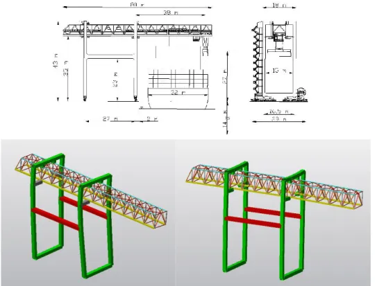
3.2 Ship to shore crane
Figure 5 shows the main geometrical parameters used for the design of this type of crane and the FEM model. The working load and the capacity is the same of the previous one.
Figure 5. Main design parameters for this type of crane and FEM model for service an out of service crane.
Figure 5 shows the main geometrical parameters used for the design of this type of crane and the FEM model. The working load and the capacity is the same of the previous one.
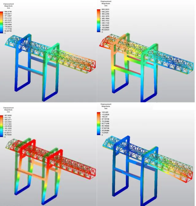
Figure 6. Von Mises stress (max value about80 N/mm^2) and displacement (max value about 100 mm) in the body of crane.
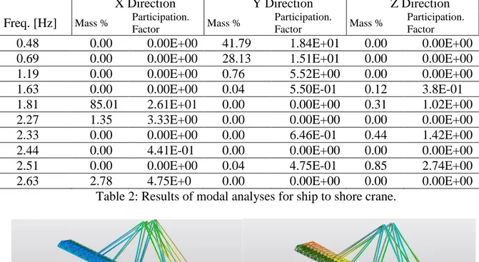
Also for this type of crane the first natural frequencies are very low. In particular, the next+ table shows the results of modal analyses.
X Direction Y Direction Z Direction Freq. [Hz] Mass % Participation.
Factor Mass %
Participation.
Factor Mass %
Participation. Factor
0.48 0.00 0.00E+00 41.79 1.84E+01 0.00 0.00E+00
0.69 0.00 0.00E+00 28.13 1.51E+01 0.00 0.00E+00
1.19 0.00 0.00E+00 0.76 5.52E+00 0.00 0.00E+00
1.63 0.00 0.00E+00 0.04 5.50E-01 0.12 3.8E-01
1.81 85.01 2.61E+01 0.00 0.00E+00 0.31 1.02E+00
2.27 1.35 3.33E+00 0.00 0.00E+00 0.00 0.00E+00
2.33 0.00 0.00E+00 0.00 6.46E-01 0.44 1.42E+00
2.44 0.00 4.41E-01 0.00 0.00E+00 0.00 0.00E+00
2.51 0.00 0.00E+00 0.04 4.75E-01 0.85 2.74E+00
2.63 2.78 4.75E+0 0.00 0.00E+00 0.00 0.00E+00
Table 2: Results of modal analyses for ship to shore crane.
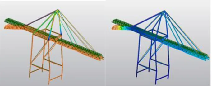
Figure 7. Displacement results for the crane subjected to the maximum earthquake load spectrum, in correspondence of the first four vibration modes.
3.3 Tower crane
The payload defined for this type of crane is 1000 kg, the length of the arm is 45m, the height is 40 m.
Figure 8. Main design parameters for a tower crane.
Figure 9. Von Mises stress (max value 230 N/mm^2) and displacement (max value 600 mm).
X Direction Y Direction Z Direction
Freq. [Hz] Mass % Participation.
Factor Mass %
Participation.
Factor Mass %
Participation. Factor
0.16 0.00 1.00E-02 13.97 1.78E+00 0.00 3.25E-03
0.26 0.00 6.04E-02 73.02 4.08E+00 0.00 7.09E-03
0.27 72.43 4.07E+00 0.01 5.46E-02 1.17 5.18E-01
0.75 15.93 1.90E+00 0.00 3.19E-03 1.11 5.04E-01
1.35 0.00 3.64E-04 1.05 4.90E-01 0.00 8.98E-03
1.60 0.72 4.06E-01 1.74 8.17E-05 57.20 3.61E+00
2.79 0.00 4.92E-03 3.34 4.90E-01 0.00 4.31E-03
3.53 0.00 3.21E-03 0.01 6.31E-1 0.00 2.59E-03
4.45 0.01 4.40E-02 0.00 8.74E-01 0.01 5.46E-02
4.49 1.96 6.70E-01 0.37 3.71E-02 5.23 1.09E+00
Figure 10. Displacement results for the crane subjected to the maximum earthquake load spectrum, in corrispondence of the first five natural vibration modes.
3.4 Portal crane
The maximum pay load is 50t, which is the average load for this type of crane. The main characteristic of this crane is the wide span (50 m, figure 11).
Figure 11. Design parameters for the crane.
X Direction Y Direction Z Direction
Freq. [Hz] Mass % Participation.
Factor Mass %
Participation.
Factor Mass %
Participation. Factor
0.50 70.60 8.63E+00 0.00 5.16E-05 0.00 6.53E-03
0.82 0.00 6.01E-03 0.00 2.77E-02 73.36 9.79E+00
0.93 0.00 2.20E-04 0.00 3.27E-04 0.00 3.02E-03
2.52 0.94 9.95E-01 0.00 1.95E-03 0.00 1.25E-03
2.96 0.00 1.03E-04 50.46 7.29E+00 0.00 3.31E-02
3.79 0.38 6.63E-01 0.00 7.44E-03 0.00 1.03E-03
6.37 0.00 1.04E-02 0.00 2.69E-04 0.00 2.18E-04
8.60 0.00 1.64E-02 0.00 4.91E-04 0.00 2.75E-04
10.25 0.00 4.99E-04 0.00 2.05E-04 0.42 6.65E-01
11.36 1.32 1.18E+00 0.00 2.07E-03 0.00 2.08E-03
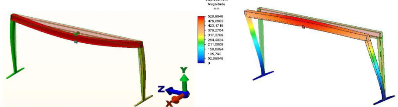
Figure 12. Displacements in correspondence of the first, the second and the fifth vibration mode and at the maximum earthquake load spectrum.
3.5 Elevating work platform.
The maximum height of the machine is 80 m and the maximum load is 250 kg in the basket corresponding to the average weight of three people. The analysed configuration is characterized by the maximum extension of the boom and maximum lifting angle (about 85°).
Figure 13
X Direction Y Direction Z Direction
Freq. [Hz] Mass % Participation.
Factor Mass %
Participation.
Factor Mass %
Participation. Factor
0.26 0.00 0.00E+00 9.67 3.21E+00 0.00 0.00E+00
0.32 9.70 3.21E+00 0.00 0.00E+00 0.13 3.69E-01
1.25 0.00 0.00E+00 4.41 2.17E-02 0.00 0.00E+00
1.55 4.32 2.14e+00 0.00 0.00E+0 0.02 1.56E-01
1.86 0.00 0.00E+00 0.00 2.49E-02 0.00 0.00E+00
2.96 0.55 7.68E-01 0.00 0.00E+00 0.57 7.82E-01
3.30 0.00 0.00e+00 2.09 1.49E+00 0.00 0.00E+00
4.57 1.72 1.35E+00 0.00 0.00E+00 0.10 1.00E-01
6.43 0.00 0.00E+00 1.16 1.11e+00 0.00 0.00E+00
8.50 1.11 1.08E+00 0.00 0.00E+00 0.04 1.98E-01
Figure 14. Displacement results for the elevating work platform subjected to the maximum earthquake load spectrum, in correspondence of the first four natural vibration modes.
4. RESULTS
The next figures show a summary of the main results performed by the finite element method code on the different lifting equipment in different load conditions [external actions (position of the load and without load, …), position of the crane, …].
Figure 15. Values of the first five natural frequencies for the boom crane: A) the maximum load and the boom are at the see side; B) the maximum load and the boom are at the port side
and C) without the load and the boom at the sea side.
Figure 16. Values of Von Mises Stress for the boom crane at different values of PGA: A) the maximum load and the boom are at the see side; B) the maximum load and the boom are at
the port side and C) without the load and the boom at the see side.
0 0,5 1 1,5 2 2,5 1 2 3 4 5 [H z] A B C D
Figure 17. Values of the first five natural frequencies for the ship to shore crane: A) the load is at 50 m; B) the load is at 12 m; C) without the load; D) out of service configuration.
0 50 100 150 200 250 300 350 400 450 B A D C V o n M is e s St re ss [ M P a] PGA_1,4 PGA_2 PGA_3,4
Figure 18. Values of Von Mises Stress for the ship to shore crane at different values of PGA: A) the load is at 50 m; B) the load is at 12 m; C) without the load; D) out of service
configuration. 0 0,2 0,4 0,6 0,8 1 1,2 1,4 1,6 1 2 3 4 5 [H z] A B C
Figure 19. Values of the first five natural frequencies for the tower crane: A) the load is at 50 m; B) the load is at 25 m; C) without the load.
Figure 20. Values of Von Mises Stress for the tower crane at different values of PGA: A) the load is at 50 m; B) the load is at 25 m; C) without the load.
0 0,5 1 1,5 2 2,5 3 3,5 1 2 3 4 5 [H z] A B
Figure 21. Values of the first five natural frequencies for the portal crane: A) the load is at the middle of the span; B) without the load.
Figure 22. Values of Von Mises Stress for the portal crane at different values of PGA: A) the load is at the middle of the span; B) without the load.
0 20 40 60 80 100 120 140 160 180 200 Stress V o n M is e s St re ss [ M P a] Static PGA_1,4 PGA_2 PGA_3,4
Figure 23. Values of Von Mises Stress for the elevating working platform in static configuration and with different values of PGA.
From the results reported above, is possible to make many considerations. For each type of lifting equipment and for each type of configuration (position of the load and configuration of the crane) the first natural frequencies are very low.
In general, the first five natural frequencies are lower than 2 Hz; at these frequencies the dynamic mass corresponds most of the mass of the lifting equipment, about 80% to 90 % of the total mass of machine.
For the action induced by an earthquake, is important to underline that the main stresses are quite related to the main intensity of the PGA (peak ground acceleration) or, in different way, the crane systems show an almost linear response in relation to the acceleration of the ground; this phenomenon is practically independent of the configuration of the crane.
The displacement of the lifting equipment induced by the strongest earthquake (maximum value of the PGA) is almost ten times greater than the displacement induced by the normal operating conditions, and so the stresses are consequently very high.
The lower spectrum assumed for the numerical elaboration, corresponding to the maximum value on Mercalli scale (more than X+ degree), shows that in this case the stresses are similar or lower than the same detectable during the normal handling operation.
It is common for all crane types that the greatest stresses are located in particular areas of the structure.
These zones are not the same of the highest stresses induced by the lifting and payload handling, but correspond to the points characterized by a high rigidity, like the joints between the horizontal and the vertical beams.
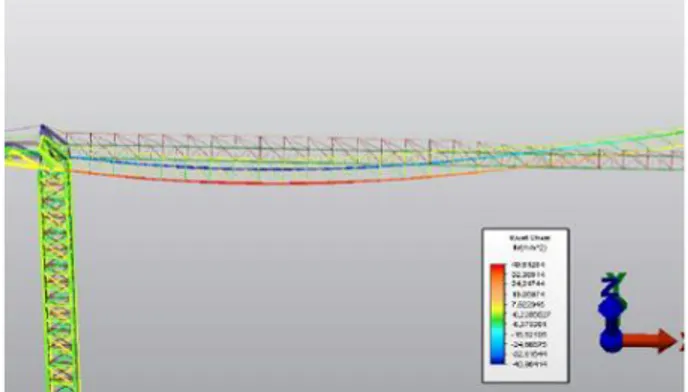
Figure 24. Different position of the maximum stress in the boom crane: a) induced by seismic actions, b) induced by lifting operations.
5. CONCLUSIONS
This paper reports the results of numerical analyses executed on the CAD models of several lifting equipment. After a preliminary design, following specific standard codes, has been applied on the models different load spectra induced by an earthquake.
The most interesting result show that in case of an earthquake characterized by an high magnitude (for example PGA=1.4) the stresses are comparable with those detectable during the normal cargo handling operations, although located in different points.
In this case is possible to reduce the effects induced by the earthquake introducing, for example, a plastic hinge, with the aim of creating a dissipative area in the structure.
In conclusions is possible to affirm that the effects of earthquake actions are generally very low because the analyzed structures show very small natural frequencies. In the seismic actions the local effect, the rigidity of the joints, etc., may be very dangerous for the structures (able to induce for example the local buckling phenomena) and assume a very high importance if compared with the normal load conditions induced by the movement of the pay load.
ACKNOWLEDGMENTS
The author wish to thank to Eng. Roberto Scalmana for support in this research.
REFERENCES
[1] M. Alamorenau, A. Vasilescu, Behaviour of Tower cranes to transversal seismic actions. The sixth Triennial International Conference of Heavy Machinery MH 2008, Faculty of Mechanical Engineering -Kraljievo, Serbia.
[2] L. Jacobs, R. DeRoches, Experimental determiantio of seismic response of port container cranes, Georgia Institute of Thecnology (2009).
[3] L. Jacobs, R. DesRoches, Large shake table of port container crane under strong motion excitation, 2010 Structure Congress.
[4] W.F. Chen , C. Scawthorn. Earthquake engineering handbook. CRC Press, 2003. [5] A.K. Chopra. Dynamics of structures: theory and applications to earthquake engineering. Prentice Hall, 1995.
[6] J. Yulong, L.Zengguang, Seismic elastic-plastic time history analysis and reliability study of quayside container crane, Earthq. Sci. 23:265-274, 2010.
[7] F. M. Mazzolani, Edifici con struttura in acciaio in zona simica, Pavia 2006.
[8] A. N. Nader, T. B. William, Nonlinear analysis of time delay position feedback control of container cranes. Nonlinear dynamics 53, 75-88, 2008.
[9] A. Sagirli, M. E. Bogoclu, V. Omurlu, Modeling the dynamic and kinematics of a telescopic rotary crane by bond graph method (part I). Nonlinear Dynamics 33, 337-351, 2003.
[10] A. Sagirli, M. E. Bogoclu, V. Omurlu, Modeling the dynamic and kinematics of a telescopic rotary crane by bond graph method: Part II. Nonlinear Dynamics 33, 353-367, 2003.
[11] L. Solazzi, Design of an elevating work platform considering both the first and the second order effects and the inertial ones. Second international Conference on Material an Component Performance Under Variable Amplitude Loading, Darmstad, Germany March 22/26, 2009.
[12] L. Solazzi, Ship to shore crane subjected to earthquake, 11th International conference on Mechanical Behaviour of Materials, June 5-9, 2011, Milano, Italy.
[13] L.Solazzi, Dynamical behavior of cranes subjected to different types of earthquake, Proceedings of the XX International Conference MHCL 2012, Belgrade, Serbia.
[14] S.Tanaka, T. Inatomi, Seismic response analysis of gantry cranes on container quay walls due to the great Hanshin earthquake. Port and Harbour Research Institute, Ministry of Transport, Nagase Yokosuka.
[15] N. Zirnic, D. Oguamanam, Dynamics and modelling of mega quayside container cranes, FME Transaction 34, 2006.
[16] C. Y. Zhang, C. M. ZHU, Z. Q. Lin, T. X. Wu, theoretical and experimental Study on the parametrically excited vibration of mass-loaded string. Nonlinear Dynamics 37, 1-18, 2004.