INNOVATIVE CATALYSTS FOR
PROCESS INTENSIFICATION
OF METHANE REFORMING
AND PROPANE
DEHYDROGENATION
REACTIONS
Antonio Ricca
Unione Europea UNIVERSITÀ DEGLI STUDI DI SALERNO
FONDO SOCIALE EUROPEO
Programma Operativo Nazionale 2000/2006 “Ricerca Scientifica, Sviluppo Tecnologico, Alta Formazione”
Regioni dell’Obiettivo 1 – Misura III.4 “Formazione superiore ed universitaria”
Department of Chemical and Food Engineering
Ph.D. Course in Chemical Engineering
(XII Cycle-New Series)
INNOVATIVE CATALYSTS FOR PROCESS
INTENSIFICATION OF METHANE
REFORMING AND PROPANE
DEHYDROGENATION REACTIONS
Supervisor
Ph.D. student
Prof. Vincenzo Palma
Antonio Ricca
Scientific Referees
Prof. Vincenzo Palma
Prof. Paolo Ciambelli
Ing. Gaetano Iaquaniello
Ph.D. Course Coordinator
Prof. Paolo Ciambelli
To Milena, my wife
Acknowledgements
Il ringraziamento più grande va al prof. Vincenzo Palma, amico e collega oltre che tutor e guida scientifica in questo triennio. La sua esperienza e la sua genialità nell'approccio alla ricerca sono sempre stati il faro rassicurante della mia attività. Grazie a lui ho imparato a proiettare i risultati verso nuovi obiettivi, e a trasformare gli insuccessi in opportunità; da lui ho attinto la vera essenza della ricerca scientifica, e la passione verso questo mondo, passione che porterò sempre con me verso ogni destinazione futura.
Un doveroso ringraziamento va al prof. Paolo Ciambelli, coordinatore del corso di dottorato e membro del comitato scientifico, nonché luminare della catalisi industriale di riconosciuto prestigio internazionale. Aver lavorato con il prof. Ciambelli è stato per me un privilegio, vanto professionale che custodirò con orgoglio.
Un sentito ringraziamento alla Prof.ssa Diana Sannino, per la sua cordialità non disgiunta dalla sua impeccabile competenza, a completare un’equipe didattica e di ricerca di ineguagliabile talento e prestigio.
Un grazie di cuore va all'Ing. Gaetano Iaquaniello, che con la sua cortese disponibilità mi ha aiutato a proiettare il lavoro della ricerca scientifica verso la realtà dell'applicazione industriale.
Un dovuto ringraziamento è rivolto all’amico Antonio Mormile e alla sua “Officina Elettromeccanica”, per il “sofferto” aiuto nella realizzazione degli impianti di laboratorio.
Ed al termine di questo percorso, come non esprimere tutta la mia riconoscenza ed ammirazione verso l’amica e collega Emma Palo, la cui professionalità è stata e sarà sempre per me l’orizzonte a cui tendere, e la cui vicinanza, dagli albori della mia carriera accademica sino a quest’ultimo traguardo, è stata sprone e gratifica negli alti e bassi di questi anni. Grazie di cuore, Emma, per tutto ciò che per me sei stata, e per ciò che sarai.
In questi tre anni ho avuto il privilegio di collaborare con tesisti eccezionali, ai quali va tutta la mia riconoscenza, e dei quali conservo in me ricordi straordinari: dalla briosità di Enrico alla travolgente vitalità di Donatella, dalla simpatia di Evrim alla straordinaria eccellenza di Marino, dalla paziente saggezza di Biagio alla freschezza di Erica. La qualità dei risultati illustrati in questa tesi è frutto anche del loro lavoro, ed a loro va tutta la mia gratitudine e stima.
Un ringraziamento speciale deve essere rivolto a Concetta, perché le ultime fasi di questo percorso di dottorato sono apparsi spesso buie e inconcludenti. La sua dolcezza e la sua pazienza mi hanno aiutato a superare le difficoltà e a ridare nuova forza alle mie giornate.
T3 del D.I.In. dell'Università di Salerno, a partire dal "capitano" Vincenzo Vaiano per proseguire con tutta la squadra, partendo dal caro Eugenio per poi passare a Daniela, Marco, Nico, Katty, Claudia, Anna, Olga, concludendo con il sempre disponibile Giuseppe. I risultati di un singolo non possono prescindere dalla buona organizzazione della squadra a cui si appartiene: grazie a tutti voi, ragazzi, per tutto il supporto che mi avete dato.
Ma in un periodo così lungo, può capitare che qualcuno abbandoni la squadra, lasciando nel cuore di chi ha avuto il privilegio di conoscerli un sentimento congiunto di gioia e malinconia. È per questo che mi piace condividere la gioia di questo traguardo con loro, partendo da Elvirosa, le cui doti umane hanno invaso il mio animo che tutt’ora non si rassegna alla sua lontananza. E come non rivolgere un pensiero a Laura, dolce e solare, sempre pronta ad un sorriso di conforto nei non rari momenti difficili. E mi si lasci condividere la soddisfazione di questi giorni con la cara Mena, uragano di dolcezza, allegria, spensieratezza, saggezza ed un pizzico di sana incoscienza; Amica con la “A” maiuscola, seppur lontana, ma sempre presente in un posto caldo del mio cuore.
Infine, voglio condividere la gioia di questo traguardo con Milena, mia moglie, ed Elio, mio figlio, perché loro più di tutti hanno sofferto la mia mancanza in questi lunghi anni di dottorato. Spero che il tempo vi permetterà di capire (e perdonare) l’assenza di un padre dalla propria famiglia, senz’altro io ho avuto modo di capire la straordinaria fortuna di avere una famiglia come voi, di avere te, Milena. questo intenso periodo di lavoro mi ha talvolta conferito una stanchezza alienante, ma non esiste migliore ricompensa dell’amore di una moglie che aspetta a casa, paziente, del sorriso di un figlio che corre tra le braccia chiamando: “Papà!”.
The research leading to these results has received funding from the European Union Seventh Framework Programme FP7-NMP-2010-Large-4, under Grant Agreement n° 263007 (acronym CARENA).
Special thanks are due to Arend de Groot, Ca.Re.N.A. coordinator, to give me the possibility to be a part of this very amazing project.
Many thanks to Frans van Berkel, WP1a coordinator, of which I have appreciated the expertise in a wide range of scientific topics as well as his uncommon interpersonal skills, and which of course gave a great contribute to my scientific enrichment.
Publication List
Palma, V., Palo, E., Ricca, A., Ciambelli, P. Compact multi-fuel autothermal
reforming catalytic reactor for H2 production. Chemical Engineering
Transactions, 25 (2011), 641-646.
Palma, V., Ricca, A., Ciambelli, P. Monolith and foam catalysts performances in
ATR of liquid and gaseous fuels. Chemical Engineering Journal, 207–208 (2012), 577-586.
Palma, V., Ricca, A., Ciambelli, P. Structured Catalysts for Methane Auto-Thermal
Reforming in a Compact thermal Integrated ATR Reformer. Chemical
Engineering Transactions, 29 (2012), 1615-1620.
Palma, V., Ricca, A., Ciambelli, P. Fuel cell feed system based on H2 production
by a compact multi-fuel catalytic ATR reactor. International Journal of Hydrogen
Energy, 38 (2013), 406-416.
Palma, V., Ricca, A., Ciambelli, P. Performances analysis of a compact kW-scale
ATR reactor for distributed H2 production. Clean Technologies and
Environmental Policy, 15 (2013), 63-71.
Palma, V., Ricca, A., Ciambelli, P. Methane auto-thermal reforming on honeycomb
and foam structured catalysts: The role of the support on system performances.
Catalysis Today, 216 (2013), 30-37.
Palma, V., Ricca, A., Ciambelli, P. Structured catalysts for methane auto-thermal
reforming in a compact thermal integrated reaction system. Applied Thermal
Engineering, 61 (2013), 128-133.
Palma, V., Palo, E., Ricca, A., Ciambelli, P. Compact multi-fuel autothermal
reforming catalytic reactor for H2 production. Conference PRES '11, 2011,
Florence (ITALY).
Palma, V., Ricca, A., Ciambelli, P. Catalytic multifuel ATR reformer for distributed
H2 production. XXIV Congresso Nazionale della Società Chimica Italiana, 2011,
Lecce (ITALY).
Palma, V., Ricca, A., Ciambelli, P. High efficiency multi-fuel catalytic autothermal
reformer for H2 production. 8th European Congress of Chemical Engineering,
2011, Berlin (GERMANY).
Palma, V., Palo, E., Ricca, A., Ciambelli, P. Fuel cell feed system based on H2
production by a compact multifuel catalytic ATR reactor. 4th European Fuel Cell
Piero - Lunghi Conference & Exhibition, 2011, Roma (ITALY).
Palma, V., Ricca, A., Ciambelli, P. Compact multi-fuel auto-thermal reformer for
H2 production. Fuel Cell 2012 - Science & Technology, 2012, Berlin (GERMANY).
thermal integrated ATR reformer: monolith and foams structured catalyst performances. The Energy and Materials Research Conference, 2012, Torremolinos (SPAIN).
Palma, V., Ricca, A., Ciambelli, P. Structured catalysts for methane auto-thermal
reforming in a compact thermal integrated ATR reformer. Conference PRES'12, 2012, Prague (CZECH REPUIBLIC).
Palma, V., Ricca, A., Ciambelli, P. Monolith and foam catalysts performances in
autothermal reforming of liquid and gaseous fuels. ISCRE22 - International
Symposium on Chemical Reaction Engineering, 2012, Maastricht (THE
NETHERLANDS).
Palma, V., Ricca, A., Ciambelli, P. Methane auto-thermal reforming in a compact
thermal integrated ATR reformer: monolithic catalysts performances. IX
International Conference on Mechanism of Catalytic Reaction, 2012, St.
Petersburg (RUSSIA).
Palma, V., Ricca, A., Ciambelli, P. Foam Catalysts performances in CH4
Auto-Thermal Reforming. DEMCAMER & Ca.Re.N.A. Workshop, 2013, Eindhoven (THE NETHERLANDS).
Palma, V., Ricca, A., Ciambelli, P. Auto-thermal reforming of methane: effect of
catalytic support structure. 9th European Congress of Chemical Engineering
ECCE9, 2013, The Hauge (THE NETHERLANDS).
Palo, E., Iaquaniello, G., Cucchiella, B., Palma, V., Ricca, A., Ciambelli, P., Akporiaye, D., Tschentscher, R. Membrane assisted propane dehydrogenation
for propylene production. 11th International Conference on Catalysis in Membrane Reactors, 2013, Porto (PORTUGAL).
Palma, V., Ricca, A., Ciambelli, P. Effect of catalyst support on methane processing
in a compact thermally integrated ATR reactor. XIth European Congress on
Catalysis, 2013, Lyon (FRANCE).
Palma, V., Ricca, A., Ciambelli, P. Methane autothermal reforming in a compact
thermal integrated ATR reformer: monolithic catalysis performances XVII
National Congress of Catalysis, 2013, Riccione (ITALY).
Palma, V., Ricca, A., Ciambelli, P. Effect of catalyst support on methane processing
in a compact thermally integrated ATR reactor. 4th International Conference on
Structured Catalysts and Reactors, 2013, Bejing (CHINA).
Palma, V., Ricca, A., Ciambelli, P. Auto-thermal reforming of methane: the role of
the catalyst support. Conference Pres'13, 2013, Rhodes (GREECE).
Palma, V., Ricca, A., Ciambelli, P. Hydrogen production by methane atr in a
compact catalytic reactor thermally integrated: structured catalysts performances analysis. 5th European Fuel Cell - Piero Lunghi Conference, 2013, Rome
Contents
INTRODUCTION 1
I.1PROPANE TO PROPYLENE 1
I.1.1THE PROPYLENE 1
I.1.2PROPYLENE PRODUCTION 2
I.1.3CATALYST 8
I.2METHANE AND HYDROGEN PRODUCTION 10
I.2.1HYDROGEN PRODUCTION TECHNOLOGIES 10
I.2.2STEAM REFORMING 10
I.2.3PARTIAL OXIDATION 12
I.2.4AUTO-THERMAL REFORMING 13
I.2.5WATER-GAS-SHIFT 13
I.3THE MEMBRANE REACTORS 15
I.4THE CARENA PROJECT 16
I.4.1UNISA IN CARENA 18
STATE OF THE ART 21
II.1METHANE REFORMING: STATE OF THE ART 21
II.2PROPANE DEHYDROGENATION: STATE OF THE ART 23
PDH THERMODYNAMIC ANALYSIS 35
III.1PURE PROPANE DEHYDROGENATION 35
III.1.1PRESSURE INFLUENCE 35
III.1.2INERT DILUTION EFFECT 37
III.1.3HYDROGEN DILUTION EFFECT 37
EXPERIMENTAL APPARATUSES 43
IV.1AUTO-THERMAL REFORMING 43
IV.1.1REACTANTS DELIVERY SYSTEM 43
IV.1.2HEAT EXCHANGE MODULE 43
IV.1.3MIXING MODULE 45
IV.1.4REACTION MODULE 45
IV.1.5ANALYSIS SYSTEM 46
IV.1.6CATALYSTS 48
IV.1.7EXPERIMENTAL PROCEDURE 49
IV.2STEAM REFORMING 51
IV.2.1TUBULAR REACTOR 52
IV.2.2ELECTRICAL OVEN 52
IV.2.3CATALYSTS 54
IV.2.4EXPERIMENTAL PROCEDURE 54
IV.3PROPANE DEHYDROGENATION 56
IV.3.1CATALYTIC REACTOR 56
IV.3.2ANALYSIS SECTION 57
IV.3.3CATALYSTS 58
IV.3.4EXPERIMENTAL PROCEDURE 59
METHANE REFORMING 61
V.1AUTO-THERMAL REFORMING (ATR) 61
V.1.1PRELIMINARY TESTS ON REACTION SYSTEM 61 V.1.2PRELIMINARY TESTS ON AL92 CATALYZED FOAM 67
V.1.3TESTS ON CATALYZED FOAMS 68
V.2METHANE STEAM REFORMING 72
V.3DISCUSSION AND CONCLUSIONS 75
PROPANE DEHYDROGENATION 77
VI.1CATALYST COMPONENTS ROLE 77
VI.2REACTION TEMPERATURE INFLUENCE 79
VI.3TUBULAR REACTOR PRELIMINARY TESTS 82
VI.4ACTIVITY TESTS ON PTSN/AL2O3 CATALYST 83
VI.5CATALYTIC SUPPORT ROLE 85
VI.6REGENERATION TESTS 88
VI.6.1S-01 SAMPLE 89
VI.6.3FEED STEAM CONTENT 94
VI.6.4PRESSURE EFFECT 95
VI.6.5CO–CO2 EFFECT 97
VI.7DURABILITY TESTS 105
VI.8DISCUSSION AND CONCLUSIONS 107
CONCLUSIONS 111
VII.1METHANE REFORMING 111
VII.2PROPANE DEHYDROGENATION 112
Index of figures
Figure I.1 Worldwide Propylene price trend from 2009 to 2011 (Lemos,
2011) ... 2
Figure I.2 UOP Oleflex Process ... 5
Figure I.3 Catofin Process: (a) feed pre-heating; (b) air heating; (c) cleaning fixed bed reactor; (d) working reactor; (e) regenerating reactor. ... 6
Figure I.4 Phillips Star process layout ... 7
Figure I.5 Snamprogetti catalytic dehydrogenation process layout: R: Reactor; R2: Regenerator; C: Depropanizer; 1: Propane; 2: reactor effluent; 3: catalyst recirculating; 4: air regeneration; 5: flue gas; 6: light ends; 7: propylene ... 8
Figure I.7 CARENA knowledge transfer scheme ... 18
Figure II.1 Coke formation mechanism (Bai et al., 2011) ... 26
Figure II.2 Proposed reaction mechanism of dehydrogenation of C3H8 in the presence of CO2 (Shishido et al., 2012) ... 27
Figure II.3 Schematic drawing of the TZFBR with two sections and membrane (Medrano et al., 2013) ... 33
Figure III.1 Thermodynamic equilibrium propane conversion vs operating temperature and pressure ... 36
Figure III.2 Thermodynamic equilibrium propane conversion vs operating temperature and inert dilution ... 36
Figure III.3 Thermodynamic equilibrium propane conversion vs operating temperature and hydrogen dilution ... 38
Figure III.4 Thermodynamic equilibrium propane conversion vs water content and operating temperature ... 40
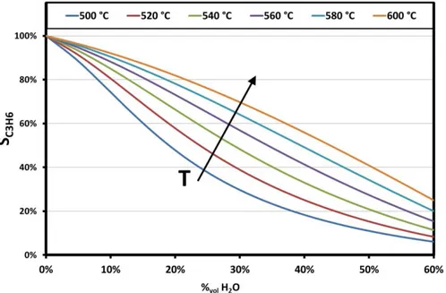
Figure III.5 Thermodynamic equilibrium selectivity to propylene vs water content and operating temperature ... 40
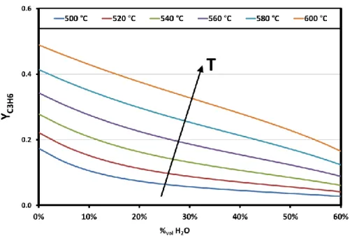
Figure III.6 Thermodynamic equilibrium propylene yield vs water content and operating temperature ... 41
Figure IV.1 Heat exchanger: disassembled and assembled views ... 44
Figure IV.2 Heat recovery module scheme ... 44
Figure IV.4 Assembled reaction system ... 46
Figure IV.5 Analysis system scheme of ATR reformer thermally integrated ... 47
Figure IV.7 Tubular reactor ... 52
Figure IV.8 Electrical oven ... 53
Figure IV.9 Oven thermal profile ... 54
Figure IV.10 Tube-shell reactor parts ... 56
Figure V.1 Temperature trend along catalyst in start-up phase ... 62
Figure V.2 Product composition and methane conversion downstream catalyst in start-up phase ... 62
Figure V.3 Temperature trend during the test (GHSV = 40000 h-1, H 2O/O2/C = 0.49/0.56/1) ... 63
Figure V.4 Composition and methane conversion during the test (GHSV = 40000 h-1, H 2O/O2/C = 0.49/0.56/1) ... 63
Figure V.5 Temperature profile along catalyst (GHSV = 40000 h-1, H 2O/O2/C = 0.49/0.56/1... 64
Figure V.6 Composition and conversion profile along catalyst (GHSV = 40000 h-1, H 2O/O2/C = 0.49/0.56/1) ... 65
Figure V.8 AL92 tests: thermal profiles (GHSV = 80,000 h-1; p = 2.5 bar) ... 67
Figure V.9 AL92 tests: Hydrogen concentration (a) and Methane conversion (b) (GHSV = 80,000 h-1; p = 2.5 bar) ... 67
Figure V.10 Gas composition and Methane conversion profiles (H2O:O2:C = 0.49:0.56:1; p = 2.5 bar) ... 69
Figure V.11 Hydrogen yield and methane conversion (H2O:O2:C = 0.49:0.56:1; p = 2.5 bar) ... 70
Figure V.12 Temperature profiles (H2O:O2:C = 0.49:0.56:1; p = 2.5 bar) ... 70
Figure V.13Methane conversion for the different catalytic foams (T = 550°C) ... 73
Figure V.14 H2 production for the different catalytic foams (T = 550°C) ... 74
Figure VI.1 Propane conversion vs time with and without catalyst and by varying catalytic formulation (WHSV = 12 h-1; T = 600°C; p = 0 barg; tube-shell reactor) ... 78
Figure VI.2 Propylene selectivity vs time with and without catalyst and by varying catalytic formulation (WHSV = 12 h-1; T = 600°C; p = 0 barg; tube-shell reactor) ... 78
Figure VI.3 Propane conversion vs time for 550°C and 600°C reactions (WHSV = 12 h-1; p = 0 barg; tube-shell reactor) ... 80
Figure VI.4 Propylene selectivity vs time for 600°C and 550°C reactions (WHSV = 12 h-1; p = 0 barg; tube-shell reactor) ... 80
Figure VI.5 Products trend (WHSV = 12 h-1; T = 550°C; p = 0 barg; tube-shell reactor) ... 81
Figure VI.6 Products trend (WHSV = 12 h-1; T = 600°C; p = 0 barg;
tube-shell reactor) ... 82
Figure VI.7 Propane conversion vs temperature in homogenous conditions for WHSV = 6 h-1 and 12 h-1 (Tubular reactor; p = 0 barg) ... 83
Figure VI.8 Propane conversion trend for the two different reaction systems (WHSV = 12 h-1; T = 600°C; p = 0 barg) ... 84
Figure VI.9 Selectivity to propylene trend for the two different reaction systems (WHSV = 12 h-1; T = 600°C; p = 0 barg) ... 84
Figure VI.10 TPR results for the Pt-Sn based catalysts ... 85
Figure VI.11 Propane conversion trend for the different Pt-Sn based catalysts (WHSV = 8 h-1; p = 0.2 barg; 20% fed steam) ... 86
Figure VI.12 Propylene selectivity trend for the different Pt-Sn based
catalysts (WHSV = 8 h-1; p = 0.2 barg; 20% fed steam) ... 86
Figure VI.13 Coke selectivity trend for the different Pt-Sn based catalysts
(WHSV = 8 h-1; p = 0.2 barg; 20% fed steam) ... 87
Figure VI.14 Reforming selectivity trend for the different Pt-Sn based
catalysts (WHSV = 8 h-1; p = 0.2 barg; 20% fed steam) ... 87
Figure VI.15 Propylene yield trend for the different Pt-Sn based catalysts
(WHSV = 8 h-1; p = 0.2 barg; 20% fed steam) ... 88
Figure VI.17 Propylene selectivity trend for S-01 sample (WHSV = 12 h-1; T
= 600°C; p = 0.6 barg; 20% fed steam) ... 90
Figure VI.18 Side-product content trend for S-01 sample (WHSV = 12 h-1; T
= 600°C; p = 0.6 barg; 20% fed steam) ... 91
Figure VI.19 Propane conversion in S-01 sample tests (WHSV = 8 h-1; T =
540°C; p = 0.2 barg; H2O/C3H8 = 0.25) ... 92
Figure VI.20 Propylene selectivity in S-01 sample tests (WHSV = 8 h-1; T =
540°C; p = 0.2 barg; H2O/C3H8 = 0.25) ... 92
Figure VI.21 Propane conversion in S-02 sample tests (WHSV = 8 h-1; T =
540°C; p = 0.6 barg; H2O/C3H8 = 0.25) ... 93
Figure VI.22 Propylene selectivity in S-02 sample tests (WHSV = 8 h-1; T =
540°C; p = 0.6 barg; H2O/C3H8 = 0.25) ... 93
Figure VI.23 Propane conversion, selectivity to propylene (a) and to coke (b), hydrogen (c) and side-products (d) distribution on fed steam content for the S-01 sample (T = 540°C; p = 0.4 barg; WHSV = 8 h-1) ... 94
Figure VI.24 Propane conversion, selectivity to propylene (a) and to coke (b), hydrogen (c) and side-products (d) distribution on fed steam content for the S-02 sample (T = 540°C; p = 0.2 barg; WHSV = 8 h-1) ... 95
Figure VI.25 Propane conversion, selectivity to propylene (a) and to coke (b), hydrogen (c) and side-products (d) distribution on fed steam content for the S-01 sample (T = 540°C; H2O/C3H8 = 0.25; WHSV
= 8 h-1) ... 96
Figure VI.26 Propane conversion, selectivity to propylene (a) and to coke (b), hydrogen (c) and side-products (d) distribution on fed steam content for the S-02 sample (T = 540°C; H2O/C3H8 = 0.25;
WHSV = 8 h-1) ... 96
Figure VI.27 Propane conversion and selectivity to propylene dependences on fed CO content for the S-02 sample (T = 540°C; p = 0.25 barg; H2O/C3H8 = 0.25; WHSV = 8 h-1) ... 98
Figure VI.28 H2,C3H6, CO and CO2 distribution dependence on fed CO
content for the S-02 sample (T = 540°C; p = 0.25 barg; H2O/C3H8
= 0.25; WHSV = 8 h-1) ... 98
Figure VI.29 CH4, C2H4, and C2H6, distribution dependence on fed CO
content for the S-02 sample (T = 540°C; p = 0.25 barg; H2O/C3H8
= 0.25; WHSV = 8 h-1) ... 99
Figure VI.30 Propane conversion and selectivity to propylene dependences on fed CO2 content for the S-02 sample (T = 540°C; p = 0.25
barg; H2O/C3H8 = 0.25; WHSV = 8 h-1) ... 99
Figure VI.31 H2,C3H6, CO and CO2 distribution dependence on fed CO2
content for the S-02 sample (T = 540°C; p = 0.25 barg; H2O/C3H8
= 0.25; WHSV = 8 h-1) ... 100
Figure VI.32 CH4, C2H4, and C2H6, distribution dependence on fed CO2
content for the S-02 sample (T = 540°C; p = 0.25 barg; H2O/C3H8
= 0.25; WHSV = 8 h-1) ... 100
Figure VI.33 Propane conversion and selectivity to propylene dependences on fed CO content for the S-02 sample (T = 540°C; p = 5 barg;
H2O/C3H8 = 5; WHSV = 8 h-1) ... 101
Figure VI.34 H2,C3H6, CO and CO2 distribution dependence on fed CO
content for the S-02 sample (T = 540°C; p = 5 barg; H2O/C3H8 =
0.25; WHSV = 8 h-1) ... 102
Figure VI.35 CH4, C2H4, and C2H6, distribution dependence on fed CO
content for the S-02 sample (T = 540°C; p = 5 barg; H2O/C3H8 =
0.25; WHSV = 8 h-1) ... 102
Figure VI.36 Propane conversion and selectivity to propylene dependences on fed CO2 content for the S-02 sample (T = 540°C; p = 5 barg;
H2O/C3H8 = 0.25; WHSV = 8 h-1) ... 103
Figure VI.37 H2,C3H6, CO and CO2 distribution dependence on fed CO2
content for the S-02 sample (T = 540°C; p = 5 barg; H2O/C3H8 =
Figure VI.38 CH4, C2H4, and C2H6, distribution dependence on fed CO2
content for the S-02 sample (T = 540°C; p = 5 barg; H2O/C3H8 =
0.25; WHSV = 8 h-1) ... 104
Figure VI.39 Durability tests results on S-02 sample (T = 540°C; p = 4.5
Index of tables
Table I.1 Main steam-cracking products ... 3
Table I.2 Typical FCC production ... 4
Table I.3 Dehydrogenation catalyst performances ... 8
Table IV.1 Heat exchange efficiency for the different heat exchange module configurations ...45
Table IV.2 Relationship between number of catalytic bricks and space velocity (GHSV) ...47
Table IV.3 Foam characteristics ...49
Table IV.4 Tube-shell reactor dimensions ...56
Table IV.5 Mass spectrometer AMU correspondence in PDH reaction analysis ...58
Table IV.6 Tested catalysts in Porpane DeHydrogenation ...58
Table V.1 Reaction trend by varying GHSV ( H2O/O2/C = 0.49/0.56/1) ...65
Abstract
In the early decade, a rapid increase in oil consumption was recorded, that led to a widening between the predicted demand for oil and the known oil reserves. Such trend, mainly due to the growing new economies, is causing a quick increasing in oil price, that effect on European chemical industry competitiveness. In this dramatic scenario, characterized by higher cost of naphtha from crude oil, the ability to exploit novel feeds such as natural gas, coal and biomass may be the keystone for the chemical industry revival. Innovating chemical processes are thus essential for the future of the chemical industry to make use of alternative feedstock in the medium and long term future. In this direction, to open new direct routes with rarely used and less reactive raw feedstock such as short-chain alkanes and CO2 appears one of the
most promising breakthrough, since in one hand it may reduce the current dependency of European chemical industry on naphtha, in the other hand may reduce the energy use and environmental footprint of industry.
Despite light alkanes (C1–C4) and CO2 are stable molecules hard to
activate and transform directly and selectively to added-value products, these challenges could be overcome thanks to relevant process intensifications along with the smart implementation of catalytic membrane reactors. Process intensification consists of the development of novel apparatuses and techniques, as compared to the present state-of-art, to bring dramatic improvements in manufacturing and processing, substantially decreasing equipment size/production capacity ratio, energy consumption, or waste production. The past decade has seen an increase in demonstration of novel membrane technology. Such developments are leading to a strong industrial interest in developing membrane reactors for the chemical industry.
The main target of the CARENA is to address the key issues required to pave the way to marketing CMRs in the European chemical industry. The UNISA contribution in CARENA project is to study and optimize supported and unsupported catalysts in order to match to membrane reactors aimed to methane reforming and propane dehydrogenation processes. The guideline of this work was fully jointed to the UNISA involving in CARENA project.
The methane reforming routes (steam- and/or auto-thermal-) are processes widely analyzed in the literature, and many studies identified Ni and Pt-group as most active catalysts, as well as the benefits of bimetallic formulation. Moreover, the crucial role of ceria and zirconia as chemical supports was demonstrated, due to their oxygen-storage capacity. In this work, great effort was spent in the reforming process intensification, in order to maximize catalyst exploit in reforming process.
In order to minimize mass transfer limitations, without precluding the catalyst-membrane coupling, several foams were selected as catalytic support, and were activated with a catalytic slurry. The performances of such catalysts
in the auto-thermal reforming and steam reforming of methane were investigated. Catalytic tests in methane auto-thermal reforming conditions were carried out in an adiabatic reactor, investigating the effect of feed ration and reactants mass rate. Tested catalysts showed excellent performances, reaching thermodynamic equilibrium even at very low contact time. By comparing foams catalyst performances to a commercial honeycomb catalyst, the advantages due to the foam structure was demonstrated. The complex foam structure in one hand promotes a continuous mixing of the reaction stream, in the other hand allows conductive heat transfer along the catalyst resulting in a flatter thermal profile. As a result, the reaction stream quickly reaches a composition close to the final value.
Steam reforming catalytic tests were carried out on foam catalysts at relatively low temperature (550°C) and at different steam-to carbon ratios and GHSV values. The catalytic tests evidenced the relevance of heat transfer management on the catalytic performances, since the samples characterized by the highest thermal conductivity showed the best results in terms of methane conversion and hydrogen yield. The beneficial effect was more evident in the more extreme conditions (higher S/C ratios, higher reactants rates), in which the heat transfer limitations are more evident.
The selective propane dehydrogenation (PDH) was one of the most attractive challenges of the CARENA project, that points to insert a membrane-assisted PDH process in a wider scheme characterized by the process stream recirculation. This approach requires to minimize inerts utilization and side-products formation. Moreover, no papers are present in literature on the concentrated-propane dehydrogenation, due to the severe thermodynamic limitations. A wide study is present in this work aimed to identify and select an optimal catalytic formulation and the appropriate operating conditions that allows the process intensification for the PDH reaction by means of a membrane reactor.
In a first stage, the relevance of side-reactions in the catalytic volume and in the homogeneous gas phase was analyzed, resulting in the optimization of the reaction system. Platinum-tin catalysts were prepared, in order to study the role of each compound on the catalytic performances and lifetime. Preliminary studies have defined the optimal operating conditions, able to minimize the coke formation and then to slow down catalyst deactivation. Several studies on catalyst support highlighted the requirement to use a basic supports with a high specific surface, able to minimize cracking phenomena.
Basing on such indications, CARENA partners provided two catalytic formulations optimized with respect the indicated operating conditions, that showed excellent activity ad selectivity. On these catalyst, the effect of the water dilution, the operating pressure and the presence of CO and CO2 was
investigated, in order to understand the catalytic formulation behavior in the real scheme conditions.
Introduction
I.1 Propane to Propylene
The synthesis of olefins, “building-blocks” in the chemical industry, is nowadays realized by the steam-cracking technology (for the production of ethylene from ethane or naphtha), catalytic cracking (used for the formulation of gasoline, where the olefins are by-products of the process), and catalytic dehydrogenation (for the selective production of propylene and isobutene). They are well-established processes, but which are characterized by very high operating costs, due mainly to the energy needed to provide heat to the highly endothermic reactions. In addition, for these processes exist the concept of economies of scale, therefore the production is cost effective only if made in large plants, for which high investment costs are needed.
I.1.1 The propylene
The propylene (CH3-CH=CH2) at room conditions appears as a colorless,
odorless and higher density than air (1.915 gL-1). It is not a toxic substance. It
shows a high degree of flammability with a flash point of 455°C. Propylene can also generate explosive mixtures with air within the following limits: 2.0 vol% (35 g/m3) - 11.1 vol% (200 g/m3).
The propylene was one of the first products in the field of petrochemical to be used on industrial scale: in its first employment in the 40s, it was used in the production of isopropanol.
Today it is the second largest commodity in the world and it is used in the production of many important intermediates in the primary chemistry, including polypropylene, acrylonitrile, cumene (in Europe), and propylene oxide.
In 2009, 87.4 million tons of propylene were produced in the world (Davanney, 2009). Since its demand is increasing, an annual production speed growth of 10% is expected, which in 2020 will lead to a production of 120 million tons. As a consequence, the propylene price (Figure I.1) had a constant increasing that led to a quadrupling from 2009 to 2011 (Lemos, 2011).
Figure I.1 Worldwide Propylene price trend from 2009 to 2011
(Lemos, 2011)
In Europe in 2012 the production capacity was about 15 million tons per year, and the price in Europe was around 1.4 $/tons (Egoy, 2012).
There are three commercial grades of propylene, which differ in the impurities content (usually propane) and are used in different applications (thermal or chemical).
The refinery-grade (which has a minimum propylene content of 65% by weight) is produced from refinery processes and is used primarily as fuel in Liquid Petroleum Gas (LPG) or to increase the octane number in gasoline for cars; can also be used in some syntheses, e.g. for the production of cumene and isopropanol.
The chemical grade (must contain 90-99.8% of propylene) is used in the production of many chemical derivatives such as acrylonitrile and oxo-alcohols.
The polymer grade (which can have no more than 0.5% of impurities) is used in the synthesis of polypropylene and propylene oxide.
Essentially all of the propylene produced for chemical purposes is consumed as a chemical intermediate in other chemical manufacturing processes, aimed to produce polypropylene, acrylonitrile, oxo-chemicals, propylene oxide, cumene, isopropyl alcohol, acrylic acid, and other chemicals.
I.1.2 Propylene production
The annual production of propylene in 2009 reached 87.4 million tons. Of these, 61.4% was obtained from steam-cracking process, 33.18% Fluid Catalytic Cracking (FCC), and only 3.3% from the catalytic dehydrogenation of propane (Nexant, 2009).
I.1.2.1 Steam-cracking
The steam-cracking is the main petrochemical process used to convert paraffins to the corresponding olefins, the primary building blocks of
chemistry. The main product of this process is ethylene, but other important co-products are propylene, butadiene and pyrolysis gas.
It consists of the pyrolysis, in presence of steam, of saturated more or less long hydrocarbons chains, at a temperature of 800-850 °C.
Fed hydrocarbons molecular weight is variable: from light paraffins to gasoline and diesel, according to the geographical areas of production. In the United States is fed primarily ethane (natural gas), while in Europe and Japan, the most widely used feed is naphtha, (naphta-cracking).
The amount of produced propylene, ethylene, butenes changes with the composition of the feed, and percentage of propylene and butenes is much greater in the case of steam cracking of naphtha (Table I.1).
Table I.1 Main steam-cracking products
Feed Naphta Ethane Feed Conversion(%) 94 69 Ethylene yield (wt%) 23.52 50.10 Propylene yield (wt%) 16.15 1.67 Butenes yield (wt%) 5.44 0.25
This is an endothermic reaction (∆H°=124.4 kJ/mol), promoted at high temperatures and low pressures, due to the increase in the number of moles. The process is conducted at about 800°C, but at atmospheric pressure: Instead of working in a vacuum system, it’s preferable to to use steam as diluent to lower the partial pressure of the feed.
The industrial process must satisfy several requirements. First of all, the reaction heat must be introduced in a very warm system; the partial pressure of the feed mist be reduced and the reaction must occur in less than 1 second. Moreover the product must be captured, in order to promote reaction balance. The reaction mixture (hydrocarbon and water vapour) passes through a series of pipes placed in a furnace heated by combustion of natural gas or fuel. The contact time in the pipes does not exceed the second, and at the furnace output the separation of the products is realized.
I.1.2.2 FCC (Fluid Catalytic Cracking)
The FCC is a petrochemical process that brings out the heavy fractions of oil to produce gasoline and diesel, but also produces gaseous light fractions C2, C3, C4.
Heavy fuels, vacuum gasoils and deasphalted oils are fed; in Table I.2 a typical product distribution obtained from the FCC is reported. The conversion of the feed reaches values of 78-80%.
Table I.2 Typical FCC production Product fraction C1,2 C3 C4 C5 C6 Light gasoil Heavy gasoil Coke % wt 1 4 10 9 48 15 8 5
The C3 fraction is composed by 76 wt% of propylene and 24 wt% of propane. The reaction is quite endothermic, is carried out at 400-500°C in the presence of amorphous silica-aluminate catalysts and zeolites in a circulating fluidized reactor. To encourage the production of short chain alkenes, small amounts of zeolite ZSM-5 zeolite in addition to the conventional Y was used.
I.1.2.3 Catalytic dehydrogenation
In the recent years, propylene and butadiene demand is increased more fastly than ethylene, therefore the traditional refinery processes are not able to satisfy the global demand. So the research activity is shifted toward solutions able to produce the only desired olefins. The most important of these is the catalytic dehydrogenation.
The catalytic dehydrogenation (DH) is realized by paraffin reduction in the corresponding olefin, by the subtraction of a molecule of hydrogen.
𝐶𝐻3− 𝐶𝐻2− 𝐶𝐻3 ⇄ 𝐶𝐻3− 𝐶𝐻 = 𝐶𝐻2+ 𝐻2
Since the reaction is endothermic and associated at an increasing of the number of moles, is favored at high temperatures and low pressures. However, the temperature increase promotes the formation of by-products such as coke and other products of thermal cracking, thermodynamically more stable. To optimize the olefin yield and minimize unwanted by-products is therefore necessary to work in conditions close to atmospheric pressure and at temperatures not exceeding 700°C.
Compared to the steam-cracking, the catalytic dehydrogenation of propane is much more selective toward propylene, although the conversion must be controlled and maintained at lower values necessarily to prevent unwanted parallel reactions. A better selectivity, despite the lower conversion, leads to an increase in yield per cycle, reaching conversion values of 20-40% for the catalytic dehydrogenation, considerably higher than values obtained in the steam-cracking (about 15% weight in the case of naphtha cracking).
The first process of catalytic dehydrogenation of butane to produce butenes has been developed and marketed since 1940 by UOP (Universal Oil Products) in the United States and by ICI in England. The butene was then converted into aviation fuel. In 1943 Phillips Petroleum performed a multi-tubular reactor for dehydrogenation in Texas. At the end of the Second World War, Houdry developed the first low-pressure process for increasing the conversion per cycle. The used catalysts were chromium and alumina based.
In 1959 in the Soviet Union an alternative technology to the Houdry’s one had been developed: the process was conducted in a fluidized bed reactor, similar to the FCC, with a continuous recirculation of the catalyst.
Since 1980, the consolidated Houdry technology was also applied to propane for the production of propylene in a process named CATOFIN.
Today there are numerous processes in the world: Oleflex UOP, ABB Lummus Crest Catofin, STAR Phillips Petroleum and FBD-4 licensed by Snamprogetti are the most important.
I.1.2.4 Olefllex UOP
The Oleflex UOP process is industrially used for the dehydrogenation of paraffins C3 and C4. In Figure I.2 is shown a process scheme, which is divided into a reaction section and a separation and products recovery section. The reaction section consists of a series of four adiabatic-stage moving bed reactor and a CCR (Continuous Catalyst Regeneration) for regeneration of the platinum based catalyst. Propane is fed in presence of hydrogen, to facilitate the removal of coke deposited on the catalyst, that causes the deactivation, but the reaction is thermodynamically disadvantaged. The reaction heat is provided by water vapour. At the exit of the reactor the zone of separation of the reaction mixture is placed: unreacted propane is recycled with an amount of hydrogen. The catalyst used is Pt, Sn, K based, supported on Al2O3.
Figure I.2 UOP Oleflex Process
I.1.2.5 Catofin ABB Lummus
The Catofin technology was initially developed by Houdry, and is currently owned by United Catalysts Inc. and licensed by ABB Lummus
Crest. In Figure I.3 the process flow-sheet is shown. The system which operates under vacuum conditions (0.5 atm) with a system of multiple fixed-bed adiabatic reactor. It is a batch process with alternating cycles of reaction and regeneration of the catalyst in a flow of steam. The reactors that alternate are five: in two of which the reaction occurs, in other two the regeneration phase takes place, and the last one is in reclamation. The total cycle has a duration of 15-30 min. The used catalyst is based on chromium oxide supported on alumina. The supplied propane is preheated with the heat produced by combustion of coke in the regeneration phase.
Figure I.3 Catofin Process: (a) feed pre-heating; (b) air heating; (c)
cleaning fixed bed reactor; (d) working reactor; (e) regenerating reactor.
I.1.2.6 STAR Phillips Petroleum
The STAR process (Steam Active Reforming) developed by Phillips Petroleum is used for the dehydrogenation of light paraffins and the dehydrociclization of C6 and C7 paraffins.
In Figure I.4 a process scheme is shown. It is a fixed bed multi-tube isothermal reactor in which simultaneously steam and propane are fed. In this way the necessary heat to the reaction is provided and the reagent is diluted to limit the formation of coke. It’s so possible to work with high total pressure to increase the conversion, but at the same low partial pressure of reagent to limit by-products production.
The catalyst, Pt promoted by Sn supported on ZnAl2O3, requires a periodic
regeneration: normally after 7 hours of reaction a regeneration is needed. Therefore for continuous operations, several reactors are needed: 7 normally operate for reaction and one in regeneration.
Figure I.4 Phillips Star process layout
I.1.2.7 FBD-4 Snamprogetti
This process works with a fluidized bed reactor. The catalyst is realized by chromium oxide supported on alumina with an alkaline promoter. The reaction heat is supplied by the circulation of hot regenerated catalyst (Figure I.5). In general this process is very similar to the FCC.
Since back-mixing phenomena occur that have a negative effect on the yield of propylene, horizontal baffles are inserted in the reactor to limit the back-flow of the catalyst. The latter circulates continuously from the reactor to the regenerator, where deposited coke is removed. Fuel is fed to the regenerator to develop heat enough to warm up the catalyst.
Figure I.5 Snamprogetti catalytic dehydrogenation process layout:
R: Reactor; R2: Regenerator; C: Depropanizer;
1: Propane; 2: reactor effluent; 3: catalyst recirculating; 4: air regeneration; 5: flue gas; 6: light ends; 7: propylene
I.1.3 Catalyst
The main catalytic systems with dehydrogenation activity reported in the scientific literature and patents are:
the Group VIII metals (mainly platinum with tin) supported on alumina with promoters;
chromium oxides on alumina or zirconia, with promoters; supported iron oxides, with promoters;
gallium oxide as a supported or included in zeolite structures: Gallium, in / on mordenite on SAPO-11, on MCM-41, of TiO2, Al2O3 on copper,
for the dehydrogenation of alcohols to aldehydes.
Including the most recent literature, the scenario of catalytic dehydrogenation and their applications are configured as shown in Table I.3.
Table I.3 Dehydrogenation catalyst performances
Catalyst Active Compound Light paraffins dehydrogenation C10-C14 Paraffins dehydrogenation Ethylbenzene- styrene dehydrogenation
Pt/Sn excellent excellent poor Cr oxides excellent weak good
Fe Oxides poor not available excellent Ga systems excellent not available excellent
Commercial applications have restricted potential catalysts to those listed below:
for ethyl-benzene dehydrogenation to styrene: Fe oxides as the only choice;
for long-chain paraffins for labs: Pt/Sn promoted on Al2O3;
for light paraffins to olefins: Pt/Sn promoted on Al2O3 and Cr2O3 on
Al2O3.
The two great families of catalysts for the dehydrogenation of paraffins (based on Pt and Cr) have been developed in parallel. These two families did not differ substantially in terms of activity and selectivity, but rather in terms of quality of some products and processes needed to complete the regeneration after the combustion of coke. Moreover, the phenomena that lead to irreversible deactivation (sintering, volatilization of the active components and morphological or phase transformations of the substrate) are typically associated with chemical species that characterize the various catalysts.
I.2 Methane and hydrogen production
Hydrogen is the lightest and the most plentiful chemical element of the universe: it’s present in the water and in all the organic compounds. It may be considered as the optimal fuel: it presents the highest energetic density, and don’t produce pollutant gases. From these considerations, we can conclude that hydrogen must be the only world energetic source, but it’s not the real situation. The motivation of this apparent contradiction is due to the fact that hydrogen is not present in the nature in free form, but it may be extracted (more or less expensively) from the substance in which it’s contented (mainly water, but also from organic compounds, alcohols, etc.). For this reason, hydrogen can’t be considered as an energetic source, but properly an energetic vector for transfer and/or stock energy. In this direction, hydrogen may be considered as the only theoretically inexhaustible energetic vector, able to satisfy the world energy demand for the next years. Moreover, it’s a zero-carbon fuels: hydrogen combustion produces steam only.
I.2.1 Hydrogen production technologies
Hydrogen may be produced mainly by 2 methods: hydrocarbons reforming (steam reforming, partial oxidation and auto-thermal reforming), or water electrolysis. Due the widespread fossil fuels distribution pipelines and their relatively low costs, the former method is preferred than the latter. Actually, only 4% of hydrogen production is obtained by electrolytical way, while hydrocarbons reforming still remain the favorite choice, and results as the most viable solution in the short and middle term.
I.2.2 Steam Reforming
The steam reforming is a chemical process in which hydrocarbons, by reacting with high temperature steam, are oxidized by extracting oxygen from water molecules and so releasing hydrogen molecules.
The process may be divided in 4 main phases: Feed purification;
Methane Steam Reforming (SR);
Further CO oxidation to produce CO2 (well note as CO-Shift or
Water-Gas-Shift);
Product purification.
Reactants purification is needed because some components (like sulphur compound) may poison catalysts used in the next stages. Instead in products purifications several by-products are removed, such as steam in excess, CO2,
CO, non-converted hydrocarbon and eventually nitrogen: the purification degree strictly depend on the further hydrogen uses.
The steam reforming is substantially exploited in the 3rd and 4th pints,
𝐶𝐻4+ 𝐻2𝑂 ⇄ 𝐶𝑂 + 3𝐻2
𝐶𝑂 + 𝐻2𝑂 ⇄ 𝐶𝑂2+ 3𝐻2
The steam reforming is an very endothermic equilibrium reaction, so external heat must be provided to the system. Further, in order to achieve high hydrocarbon conversion, high operating temperature (higher than 700°C) is needed. Too high temperature is not a viable solution, because, in order to sustain the endothermic reaction, external heat must be supplied at a very warm system, by using heater means warmer than system, and so several problems due to the material thermal resistance may occur. Therefore, in the industrial processes, the steam reforming reaction is performed in 2 stages: in a first stage methane and steam react at 700-800°C, so obtaining a hydrocarbon conversion up to 90%. In the second stage, an amount of air (or oxygen) is added to the reforming gas, that reacts with a part of produced hydrogen. The heat generated to this reaction increase reaction mixing temperature op to 1000-1200°C, so allowing a quasi-complete hydrocarbon conversion. This process is carried out a very high temperature, and therefore don’t undergoes to kinetic limitations, and it easily reach thermodynamic equilibrium. However, the steam reforming reaction may be followed by several side-reactions, that lead to the coke formation:
2𝐶𝑂 ⇄ 𝐶𝑂2+ 𝐶
𝐶𝑂 + 𝐻2⇄ 𝐶 + 𝐻2𝑂
𝐶𝐻4⇄ 𝐶 + 2𝐻2
The steam reforming is a catalytic reaction: the most common catalysts are Nickel or Platinum supported on calcium aluminate, that assure a good selectivity towards the reforming reactions and avoid coke formation. The support has the twice function of improve the mechanical properties of cat6alytic system and of increase the surface/mass ratio.
The steam reforming reaction is characterized to an increase in total molar number and therefore it’s favored in low pressure conditions. Steam-to-carbon ratio must be as higher as possible, both to favor products formation and to avoid coke formation. However, too high steam-to-carbon ratio results as a non-ideal operating condition, mainly because to the expensive pre-heating of the fed steam.
The “top-fired” are the most common steam reforming reactors, designed as a tube-shell heat exchanger, in which tube-side reactants flow, on the top of the shell a burner is placed to the heat generation, and combustion gas flows shell-side so providing heat to the reactants in the tubes. Naturally, catalyst is placed inside the tubes. This systems have very large sizes (e.g. in order to produce 5000 Nm3/h of syngas a plant sized 3 x 6 x 11 m is required), and
A little innovation is achieved by the using of plate-exchangers reactors: this solution lead to great benefits for the reduction in plant size, while several problems due to pressure drop and operating limitations may be exceeded.
I.2.3 Partial Oxidation
The methane partial oxidation consists on a hydrocarbon oxidation with an oxygen content less than stoichiometry.
𝐶𝐻4+ 1
2𝑂2⇄ 𝐶𝑂 + 2𝐻2 ∆𝐻𝑟𝑒𝑎𝑐
0 = −35.6𝑘𝐽/𝑚𝑜𝑙
It’s an exothermic reaction, characterized by a very fast kinetic, that assures contact time very low: this feature allows reaction plants very smaller than steam reforming.
However, partial oxidation implies a lower hydrogen yield, in fact e moles of hydrogen are achieved from a mole of methane, while in the case of steam reforming 3 moles of hydrogen are achieved.
In a mechanistic hypothesis, the methane partial oxidation results as the following of several reactions. In a first time, the total oxidation of an amount of hydrocarbon occurs:
𝐶𝐻4+ 2𝑂2⇄ 𝐶𝑂2+ 2𝐻2𝑂
The combustion heat is partially used to supply steam reforming and dry reforming reactions:
𝐶𝐻4+ 𝐻2𝑂 ⇄ 𝐶𝑂 + 3𝐻2
𝐶𝐻4+ 𝐶𝑂2⇄ 2𝐶𝑂 + 2𝐻2
The partial oxidation reaction don’t need any catalysts, showing good performances for temperatures between 1300 and 1500°C, assuring in the selected conditions a full hydrocarbon conversion and decreasing coke and soot production. The absence of catalysts allows to avoid feed desulphurization, with a notable cost saving. However, such high temperatures make the process hardly controllable, therefore lower temperatures (800-1000°C) are preferred, by using a catalytic system. In these conditions we have a fast reaction kinetic, and side-reactions are avoided. The most common catalyst is nickel or rhodium based: the first one don’t exclude coke formation, while the second is very more expensive.
Downstream the partial oxidation reactor, as in the case of steam reforming, a Water-Gas-Shift stage is needed, followed by a product stream purification stage.
I.2.4 Auto-thermal Reforming
The auto-thermal reforming results as a compromise solution between steam reforming and partial oxidation, in which both reactions occurs. By this process from one hand well product composition and hydrocarbon conversion are achieved, from the other no external heat must be supplied.
Fuel (methane), steam and air (or oxygen) are inserted in the reactor. The oxygen reacts with the hydrocarbon in combustion and partial oxidation reactions, so generating an amount of energy further used from the system for the steam reforming reaction between steam and remaining methane. So, the heat produced for the one reaction is used to by the second in the same reactor, so no external heat is needed.
Globally, the reaction may be summarized as:
𝐶𝐻4+ 𝑥𝑂2+ 𝑦𝐻2𝑂 ⇄ 𝑎𝐶𝑂 + 𝑏𝐶𝑂2+ 𝑐𝐶𝐻4+ 𝑑𝐻2𝑂 + 𝑒𝐻2+ 𝑓𝐶(𝑠)
Obviously, d represents the excess water and (a+b+c)=1. The reaction enthalpy (∆H°react) depends of feed parameters (x, y).
The auto-thermal reforming reaction is very flexible and controllable, by varying x and y parameters as needed. Moreover, between the fuel processes analysed for the hydrogen production, the auto-thermal reforming has the lowest coke formation.
Because of no external heat must be provided to the system, no heat exchangers, steam generators or burners are needed; this feature allows very smaller plants than the former systems, and scale-sized plants are easier to realize.
Auto-thermal reforming is a catalytic process: because it’s the synthesis of steam reforming and partial oxidation, the selected catalyst must either favour hydrocarbon oxidation and assure high reforming degree. Conventionally nickel oxide based catalysts based on alumina, calcium oxide and magnesium oxide are used.
I.2.5 Water-Gas-Shift
Downstream all the three analysed processes, a further purification stage is needed: it’s the water-gas-shift (WGS) reaction. Mainly, carbon monoxide must be removed from the stream outgoing to the reforming stages, by reacting with steam: by this reaction a further mole of hydrogen was produced for each mole of CO converted.
𝐶𝑂 + 𝐻2𝑂 ⇄ 𝐶𝑂2+ 𝐻2 ∆𝐻𝑟𝑒𝑎𝑐0 = −41𝑘𝐽/𝑚𝑜𝑙
The reaction is weakly exothermic, and is thermodynamically favoured at relatively low temperature (< 200°C). But low temperatures implies slow kinetics, therefore catalysts are needed in the process. Since it’s an exothermic
reaction, by using an adiabatic reactor, CO conversion develop a reaction heat that increase reaction stream temperature, so decreasing thermodynamic CO conversion. In order to reduce this phenomenon, preferentially the process is split in in 2 stages, separated by a stream cooling.
The first stage, known as high-temperature water-gas-shift (WGS-HT), is performed at about 350°C, by using an iron-chrome based catalyst.
The second stage, known as low-temperature water-gas-shift (WGS-LT), is performed at about 220°C, by using a copper-zinc based catalyst.
I.3 The membrane reactors
Membrane reactors facilitate simultaneous rate based reactive separation schemes. In addition to the key attributes of membrane technology such as membrane stability, lower catalyst deactivation, higher selectivity and yield, and low cost, the optimal performance of a membrane reactor involves the combinatorial selection of key process variables such as reaction and permeation temperatures, retentate and permeate zone pressures, membrane area per unit volume and membrane thickness. The capability of membrane reactors to enhance reactor conversions has been demonstrated experimentally for different schemes such as dehydrogenation and hydrogenation, oxidative dehydrogenation and other reversible reaction schemes. Based on experimental study of membrane reactors, several literatures attempt to aggrandize the economic potential of membrane reactors, with a basic rule of thumb that enhancement of reactor conversions directly translate into higher profit margins and hence economic competitiveness.
Nonetheless, the admirable characteristics for membrane reactors in process industries have been summarized by Armor (1998), who indicated several materials performance issues for their industrial applicability. These have been summarized as fabrication of crack free thin composite membranes with materials not susceptible to poisoning or fouling, developing compatible membrane-support combinations that can resist temperature cycling, balance between catalyst and membrane distributions for optimal heat and mass transport. Therefore, a first step towards the selection of membrane reactors for industrial schemes involves a mandatory exercise on the materials performance issues.
Based on simulations conducted for various process schemes associated to fluidized membrane reforming, Roy et al. (1998) concluded that the cost of producing hydrogen from membrane integrated fluidized reformers was 5% lower than the cost affordable to produce hydrogen by best configurations deploying conventional reactor technology only. Petersen et al. (1998) concluded that the membrane integrated reforming process is not competitive to the traditional steam reforming process and only with exceptional unit costs of power and membranes could make the membrane integrated reforming process an inexpensive and attractive alternative for reforming.
A number of metal membranes are highly hydrogen selective at higher temperatures. Especially palladium and platinum can therefore be used for the production of highly purified hydrogen from steam reforming of gases. Ultra-pure hydrogen, generated from these reactions, is extracted by use of thin dense metallic membranes that are 100% selective to hydrogen. The mechanism of the transport is the separation of hydrogen into protons and electrons at the surface and recombination on the filtrate or raffinate side.
Hydrogen selective membranes offer the possibility of combining reaction and separation of the hydrogen in a single stage at high temperature and
pressure to overcome the equilibrium limitations experienced in conventional reactor configurations for the production of hydrogen. The reforming reaction is endothermic and can, with this technique, be forced to completion at lower temperature than normal (typically 500-600°C). The shift reaction being exothermic can be forced to completion at higher temperature (300-450°C). Membrane reactors allow one-step reforming, or a single intermediate water gas shift reaction, with hydrogen separation (the permeate) leaving behind a retentate gas which is predominantly CO2 and steam, with some unconverted
methane, CO or H2. After clean-up, condensation of the steam leaves a
concentrated CO2 stream at high pressure, reducing the compression energy
for transport and storage. The need for multiple shift reaction stages is avoided. Moreover, process intensification with membrane reactors allows for more compact units, lower investment cost, higher yields and reduced energy cost. In the same way, hydrogen removing from the products may force dehydrogenation reactions, thermodynamically limited, towards further hydrogen production, and therefore increase hydrocarbon conversion.
However, some problems must be exceeded to obtain a stable and optimal membrane using. The greatest limit of membrane reactors concerns the operating temperature of a membrane. Previous studies have demonstrated that high temperature reduces the membrane life, as well as the membrane perm-selectivity. By working to temperature typical of reforming or dehydrogenation processes, not only hydrogen permeates the membrane, but also other stream components, so reducing the desired benefits.
I.4 The CARENA project
(CAtalytic membrane REactors based on New mAterials for C1-C4 valorization)
The last decade has seen an increase in dempstration of novel membrane technology, mainly in the carbon capture and fuel cell fields, bringing this technology out of the labs. Dense conducting membranes have been demonstrated at pilot-scale. These developments are leading to intensified industrial interest in developing membrane reactors for the chemical industry. The objective of the CARENA project is to develop and implement novel nano-structured materials and optimized chemical processes to enable the efficient conversion of light alkanes into higher value chemicals resulting in the reduction in the number of process steps and increase in feedstock flexibility for the European chemical industry.
CARENA aims to achieve break-through in catalytic membrane materials and processes at 3 levels:
1. Enable selective conversion of raw feedstock such as light alkanes (C1-C3) by generating in situ active species). The integration of catalyst and membrane will be optimized.
2. Develop reactor concepts, that match and control highly intensified rates of mass and heat transfer resulting from application of novel materials and architectures. Process intensification combining in-situ reaction and reparation will be designed for equilibrium-limited reaction for high industrial relevance.
3. Create novel process schemes, that translate novel materials and reactions concepts into innovative industrial processes that exploit the opportunities, such as reduction of the number of process steps and elimination of energy intensive separations.
CARENA focuses on the activation of three specific primary feedstock: methane, propane and CO2. The integrated scheme of process is shown in
Figure I.6.
Figure I.6 CARENA's integrate scheme of process The main routes are:
a) Indirect and direct route for conversion of methane into olefins and methanol
b) (Oxidative) dehydrogenation of propane and subsequent selective oxidation of a propane/propylene mixture to acrylic acid.
c) Direct conversion of CO2 into dimethyl carbonate (DMC) and
dimethylether (DME) and methanol (MeOH).
To achieve competitiveness and sustainability of new chemical processes through the development of highly innovative nano-structured materials and optimized membrane-reactors, scientific excellence needs to be combined
with industrial know-how of leading businesses. CARENA brings together companies and institutes from 8 European countries. European chemical companies as AkzoNobel and Arkema ensure a strong industrial leadership to the project. Technology providers and developers include Johnson Matthey, StGobain, Technip KTI, Linde, Acktar and PDC. Scientific excellence is strengthened with top-level academic partners and research institutes: CEA, ECN, SINTEF, CNRS-IEM, CNRS-IRCE, Diamond, Technion, Universities of Salerno, Twente and Hannover. As a very complex and effective operating network, activities of each partners are arranged in a level and multi-task scheme (Figure I.7) able to exploit the skills of the involved partners in a common research pathway.
Figure I.7 CARENA knowledge transfer scheme
I.4.1 UNISA in CARENA
In order to contribute in the CARENA project, the University of Salerno will perform several tests on the catalytic activity in some of the selected process in the project.
As a first, reforming of methane will be studied. The screening of different structured catalyst supports (ceramic and metal substrates, like honeycomb, foam and wires) covers great importance in the process intensification. The individuation of optimal support to couple to a membrane reactor results as a fundamental step in the catalyst preparation. Long term tests will be performed
with the selected coated catalyst samples at reforming conditions, in order to evaluate the support efforts and the stability of the system.
Great attention was aroused on the propane dehydrogenation, in order to obtain high selective processes by starting from pure propane. The formulation of novel catalyst-support combination, active in the selected operating conditions, results as a starting point towards novel membrane catalytic reactors. In this objective, UNISA should understand the effect of the operative conditions in the PDH performances, by validating and supporting numerical evaluations carried out by partners. In this aim, UNISA will test catalysts prepared by partners, so understanding any weakness of the formulations and eventually suggesting appropriate modifications.