Advances in carbon nanofiber-based
supercapacitors
Allan Daragmeh
Aquesta tesi doctoral està subjecta a la llicència Reconeixement- NoComercial – CompartirIgual 4.0. Espanya de Creative Commons.
Esta tesis doctoral está sujeta a la licencia Reconocimiento - NoComercial – CompartirIgual 4.0. España de Creative Commons.
This doctoral thesis is licensed under the Creative Commons Attribution-NonCommercial-ShareAlike 4.0. Spain License.
ADVANCES IN CARBON NANOFIBER-BASED
SUPERCAPACITORS
Advances in carbon nanofiber-based supercapacitor
Allan DaragmehDirectors de tesi. Dr. Albert Cirera Hernández i Dr. Llorenç Servera Serapio
Advances in carbon nanofiber-based
supercapacitor
MEMORIA PRESENTADA PER OPTAR AL GRAU DE DOCTOR PER
LA UNIVERSITAT DE BARCELONA
PROGRAMA DE DOCTORAT EN NANOCIÈNCIES
Autor: Allan Daragmeh
Adreça de correu electrònic: [email protected] ,[email protected]
Títol: Advances in carbon nanofiber-based supercapacitor Universitat de Barcelona
Departament d'Enginyeria Electrònica i Biomèdica
Àrea de coneixement: Nanociències Direcció de la tesi:
Dr. Albert Cirera Hernandez Dr. Llorenç Servera Serapio
Advances in carbon nanofiber-based
supercapacitors
Summary report
Nowadays, our modern society huge challenges related to energy, savings as well as energy management, to improve and extend the standar of living to a growin population over 7000 million people, and do it with sustainable technologies becomes our main survival role play. Energy storage is a critical question to obtain a complete energy management system. Storage devices, suitably controlled by modern fast power electronic converters, may play a fundamental role in facing the challenge of global energy savings. In the present work, a new storage system based in electrochemical double layer capacitor has been developed and tested. The present doctoral thesis gives background related to energy storage based on supercapacitors. It attempts to place the supercapacitor device in context of available and future technologies for alternative energy systems management. Limitations of cells and electrodes are introduced. Ionic transport in active carbon and carbon nanofiber electrodes and possible restrictions in carbon nanostructured porous systems are studied and a novelty method to solve them are described. There are some open issues in the supercapacitor development, in this thesis the major challenges are introduced and how we can go beyond them, become the major objective. The results from the studies are presented in this thesis together with the scientific papers this thesis is based on.
Resum
Avui en dia, en les societats modernes, tenim l’important repte de fer sostenible el consum d’energia i al mateix temps salvaguardar els estàndards de qualitat de vida, en un planeta amb mes de 7.000 milions de persones, per això en l’acord de Paris (2015) es va marcar com objectiu que l’increment de temperatura mundial quedi per sota dels 2ºC, per aconseguir aquest objectiu s’han de reduir les emissions de gasos que influeixen negativament en l’efecte hivernacle.
Reduir les emissions de gasos passa per un us mes racional de les diferents fonts d’energia, prioritzant l’energia elèctrica, que ha mostrat ser la menys contaminat. Un ús eficient de l’energia elèctrica passa pel desenvolupament de nous sistemes per emmagatzemar l’energia elèctrica, tant pel seu ús en sistemes de transport com per el nou paradigma de les ciutats intel·ligents.
En aquest treball s’ha proposat:
1.- Estudiar els sistemes d’emmagatzematge elèctric basats en supercondensadors, des de les diferents parts que formen el supercondensador, s’han analitzat a fons les tres parts principals que conformen el supercondensador: Els elèctrodes, els separadors i l’electròlit. S’ha dedicat un especial esforç al estudi i disseny de nous elèctrodes, per això, s’han fet servir nanofibres de carbó, comprovant l’efecte del dopat de les nanofibres de carboni amb òxid de manganès millora de forma notable els valors de la capacitat especifica, arribant a valors de 812 F/g mesurats amb una rampa de tensió de 5 mV/s, i també, pensant en una futura industrialització del procés de fabricació, s’ha estudiat en profunditat la concentració i el tipus de polímer que es pot fer servir com a “binder” per mantindré l’estructura mecànica del elèctrode.
2.- Desenvolupar un nou sistema basat en l’ús de nano estructures carbonoses per la fabricació d’elèctrodes de supercondensadors de alta eficiència. S’ha estudiat l’efecte de fer servir nanofibres de carbó juntament amb carbó activat per millorar la resposta tant pel que fa a la capacitat especifica com a la resistència sèrie equivalent (ESR), s’han obtingut valors de capacitat especifica de 334 F/g fent servir únicament carbó activat i
de 52 F/g amb nano fibres, fent servir sempre una rampa de tensió de 5 mV/s. Pel que fa a la ESR, les nanofibres, com era d’esperar, ens proporcionen el valor mes baix (0.28 Ω) en comparació als valors obtinguts fent servir carbó activat (3.72 Ω).
Per aprofitar les millors característiques de les nano fibres i del carbó activat, s’ha estudiat quina es la millor relació entre elles: (90% de AC / 10% de CNFs) amb això el millor valor obtingut ha estat de 207 F/g.
3.- Estudiar el fenomen de la conductivitat iònica a l’interior de les estructures carbonoses dels elèctrodes i desenvolupar una millora que permeti reduir la resistència sèrie equivalent (ESR). Pensant en la sostenibilitat, s’ha dedicat un esforç especial al estudi i desenvolupament d’electròlits en base aquosa, que permetin optimitzar els valors de resistència sèrie equivalent (ESR) al mateix temps que s’ha evitat fer ús de productes nocius pel medi ambient o que requereixin de processos industrials complicats per la seva obtenció. En base a això, s’ha comprovat que el millor electròlit de base aquosa es la dissolució 1M de KOH, malgrat que aquesta es reactiva a l’alumini i complica el posterior procés d’encapsulat. Finalment s’ha optat per el sulfat de sodi (Na2SO4) que ha estat fet servir com ha referencia en bona part del estar del art, malgrat això, s’ha comprovat que la concentració del aigua del Mart Mort, que conté bàsicament clorurs de magnesi i potassi també dona uns resultats acceptables.
4.- Estudiar els efectes de la auto descàrrega i proposar un nou tipus de separadors que permeti millorar aquest paràmetre, seguint el model del supercondensador, seria fer que la resistència paral·lel sigui d’un valor el mes gran possible. Un dels elements constituents dels supercondesandors que ha estat poc estudiat en la literatura científica es el separador, habitualment es fa servir cel·lulosa, en aquest estudi s’ha estudiat l’efecte del separador de cel·lulosa en comparació amb un separador de fibra de vidre i per últim s’ha comprovat que les membranes conductores iòniques, que habitualment es fan servir en les bateries de flux, ens proporcionen els millors resultats pel que fa als valors de la resistència paral·lel.
Acknowledgements
This thesis is dedicated to the Palestinian people and to all people that make a lot effort to achieve scientific improvements. Many thanks to my advisor Dr. Albert Cirera and Dr. Llorenç Servera to lighting the path in my work. Special thanks to Dr Shazad Hussain and all the researchers in the nanoelectronics lab for their help and support. Special thanks and appreciation for committee of AVEMPACEIII/Erasmus Mundus program for giving me the chance to pursue my PhD degree at Universitat de Barcelona. This work would not have been possible without the unconditional support of my parents, brothers and sisters. Thanks to them for encouraging supporting and loving me.
Contents Summary report ... i Resum ... ii Acknowledgements ... iv List of figures ... ix Background ... xiii
Objective of thesis ... xvii
Structure of thesis ... xviii
References ... xx
Chapter 1:Super Capacitor ... 1
1.1. Overview. ... 1
1.2 Principle of supercapacitor ... 2
1.2.1 Electric double layer ... 5
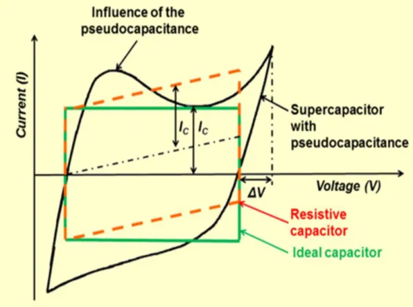
1.2.2 Pseudocapacitors ... 8
1.3 Electrode materials for supercapacitors ... 9
1.3.1. Carbon material for supercapacitors ... 9
1.3.2. Activated carbons (ACs) ... 12
1.3.3. Carbon nanofibers (CNFs) ... 14 1.3.4. Carbon nanotubes (CNTs) ... 16 1.3.5. Graphene ... 16 1.3.6. Carbide-derived carbons ... 17 1.4. Pseudo-capacitive contributions ... 18 1.5. Electrolyte ... 20 1.5.1. Aqueous Electrolytes ... 20 1.6. Membrane separator ... 22
Chapter 2: Materials Characterization and Electrochemical Techniques ... 30
2.1. Materials and Chemicals ... 31
2.2.1 Brunauer-Emmett-Teller Surface Area and Barrett-Joyner-Halenda Pore Size and
Volume Analysis ... 33
2.2.2. Scanning Electron Microscopy and Transmission Electron Microscopy ... 36
2.2.2.1. SEM ... 36
2.2.2.2. TEM ... 36
2.2.2.3 Raman Spectroscopy ... 37
2.3.1. GAMRY Reference 600 ... 39
2.3.1.1. PHE200™ Physical Electrochemistry Software ... 40
2.3.1.2. EIS300™ Electrochemical Impedance Spectroscopy ... 40
2.3.1.3. PWR800 Electrochemical Energy Software ... 40
2.4. Electrochemical measurements ... 43
2.4.1. Cyclic voltammetry (CV) ... 43
2.4.2. Constant Current Techniques ... 45
2.4.3. Electrochemical Impedance Spectroscopy (EIS) ... 46
Chapter 3: Flexible supercapacitors based on low-cost tape casting of high dense carbon nanofibers ... 50
3.1. Introduction ... 50
3.2. Experimental setup ... 52
3.3. Results and discussion ... 54
3.4. Conclusions ... 67
Chapter 4- A study of Carbon nanofibers and Active carbon as symmetric supercapacitor in aqueous electrolyte ... 73
4.1 Introduction ... 73
4.2. Experimental procedure ... 74
4.2.1. Preparation of AC and CNFs electrodes ... 74
4.2.2. Surface characterization ... 75
4.2.3. Morphological characterization ... 75
4.2.4. Electrochemical characterization ... 75
4.3. Results and discussion ... 75
4.3.1. Morphological characterization ... 75
4.3.2. Pore texture of CNFs and AC ... 76
4.4. Effect of carbon structure and porous texture on EDLC performance ... 90
4.5. Conclusions ... 90
Chapter 5: Impact of PVDF concentration and pressing force on performance of symmetric CNFs based supercapacitors ... 94 5.1. Introduction ... 94 5.2. Experimental procedure: ... 95 5.2.1. Electrode Preparation ... 95 5.2.2. Morphological characterization... 96 5.2.3. Surface characterization ... 97 5.2.4. Electrochemical characterization ... 97
5.3. Results and discussion... 97
5.3.1. Morphological characterization... 97
5.3.2. Surface area and Pore texture of CNFs ... 97
5.3.3. Electrochemical measurement... 100
5.4. Correlation between BET surface area and Porous Texture on EDLC Performance 108 5.5. Conclusions. ... 109
Chapter 6: Carbon nanofibers/Activated carbon composite for supercapacitor applications ... 114
6.1. Introduction. ... 114
6.2. Experimental procedure. ... 116
6.2.1. Surface characterization ... 117
6.2.2. Morphological characterization... 117
6.2.3. Electrochemical characterization ... 117
6.3. Results and discussion... 118
6.3.1. Morphological characterization... 118
6.3.2. Pore size distribution of carbon material samples. ... 119
6.3.2. Electrochemical characterization. ... 122
6.3.2.1. Cyclic Voltammetry. ... 122
6.3.2.2. Galvanostatic charge discharge (GCD) ... 126
6.3.2.3. Electrochemical Impedance Spectroscopy ... 131
6.4. Correlation between BET, porosity sample and specific capacitance ... 135
Future work ... 144 Publications referred to in the thesis ... 145 Contribution to the papers ... 145
List of figures
Figure 1.1.(a) Ragone plot of various energy storage and conversion devices. Figure
from Winter and Brodd --- xiv
Figure 1.1.(b): Taxonomy of supercapacitors.---2
Figure 1.2: Schematic illustration of the charging/discharging process in a supercapacitor ---4
Figure 1.3. (a) Helmholtz, (b) Gouy-Chapman, and (c) Stern model of the electrical double-layer formed at a positively charged electrode in an aqueous electrolyte. The electrical potential, ∅, decreases when transitioning from the electrode, φ e , to the bulk electrolyte infinite away from the electrode surface, ∅ s . The Stern plane marks the distance of closest approach of the ions to the charged surface. Note the absence of charges/ions in the Stern layer. The diffuse layer starts in the range of 10 – 100 nm from the electrode surface.--- 6
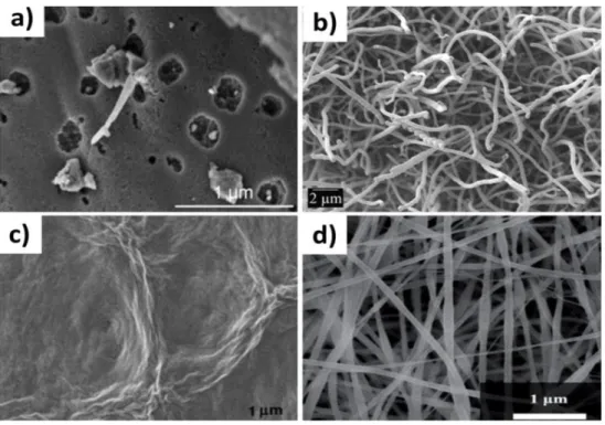
Figure 1.4. SEM images of a) activated carbon, b) multi-walled carbon nanotubes, c) graphene, and d) carbon nanofibers ---10
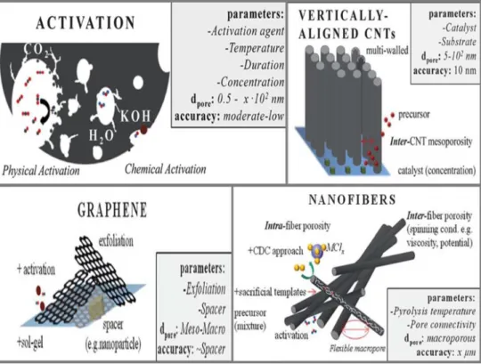
Figure 1.5. Different carbon nanostructures and parameters affecting the material properties ---13
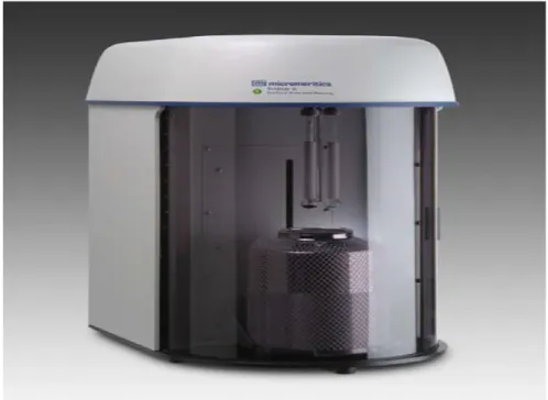
Fig 2.1 Micromeritics TriStar 3000 V6.04 A---34
Figure 2.2 (a) Basic types of physical adsorption isotherms and (b) types of hysteresis Loops---36
Fig. 2.3 An FE-SEM facility (Jeol J-7100). --- 37
Fig.2.4 a commercial TEM setup (.JEOL 2011)---37
Fig.2.5 shows a Renishaw inVia Raman Microscope. ---38
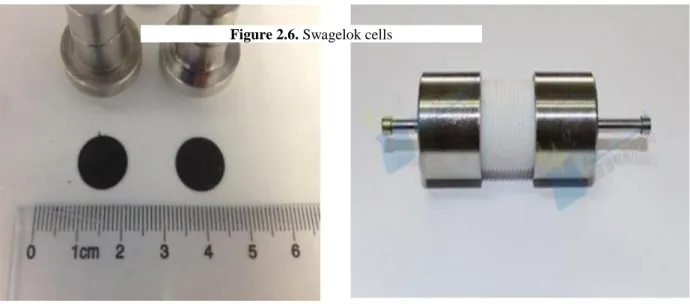
Fig 2.6 Swagelok-type PFA cell---39
Fig 2.7 GAMRY INSTRUMENT---39
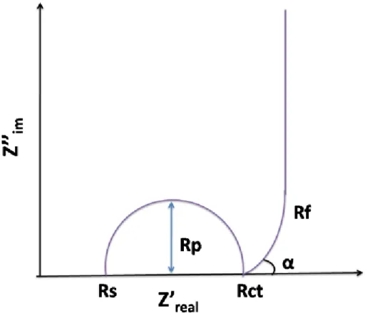
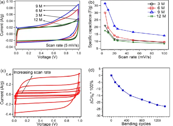
Fig 2.9 Schematic of typical electrochemical capacitor showing the differences between static capacitance (rectangular) and faradaic capacitance (curved)--- 45 Fig 2.10 Components of a Nyquist plot for a supercapacitor---47 Figure 3.1. (top) schematics of the tape casting process including slurry formulation and tape cast, (bottom left) image of the casted carbon nanofibers in a rolled tape, (bottom right) flexibility of the CNF tape.---53 Figure 3.2. (a) Cyclic voltammogram comparison at a scan rate 5 mV/s for different concentration of KOH, (b) Specific capacitance comparison at different scan rates, (c) Cyclic voltammogram at different scan rates of (5, 10, 20, 25, 50 and 100 mV/s) for 6 M KOH as electrolyte, (d) Capacitance retention as a function of bending numbers. - 56 Figure 3.3.Nyquist plot at different electrolyte concentrations of KOH.---58 Figure 3.4. SEM images and TEM images (inset) for (a)CNFs, (b)S1,(c) S2 and (d)S3.---59 Figure 3.5.Raman spectra of CNFs, S1, S2 and S3.---60 Figure 3.6. (a) Cyclic voltammetry comparison between various samples at 5 mV/s scan rate, (b) Specific capacitance comparison at different scan rates, (c) Cyclic voltammograms at different scan for S1 (5, 10, 20, 25, 50 and 100 mV/s). ---61 Figure 3.7. (a) Charge /discharge curves at different current for S1, (b) Ragone plot of specific power against specific energy for S1, S2 and S3, (c) Charge/discharge cyclic stability of supercapacitors with S1, S2 and S3, (d) Nyquist plot for S1, S2 and S3.----62 Figure 3.8. (a) Nitrogen adsorption/desorption isotherms, (b) BET surface area, (c) Pore size distribution. ---66 Figure 4.1 .SEM images and TEM images (inset) for (a) CNFs, (b) AC.---75 Figure 4.2.Nitrogen adsorption/desorption isotherms, (a) CNFs, (b) AC. BET surface area (c) CNFS, (d) AC.--- 77
Figure 4.3. Pore size distribution (a) CNFs by BJH method, (b) AC by MP method.--78 Figure 4.4. (a, b) CVs of CNFs and AC respectively at 5, 10, 20, 50, 100, 150, 500 mV/s scan rates, (c, d) specific capacitance comparison at different scan rates, (e, f) CVs of CNFs and AC respectively from 1st to 100th cycle. ---81 Figure 4.5. (a) GCD curves at different current densities of CNFs, (b) GCD curves at different current densities of AC.---82
Figure 4.6. (a) Specific capacitance comparison from discharge curve of GCD, (b) Ragone plot of specific power against specific energy for CNFs and AC, (c) Cycling stability of CNFs and AC.---83 Figure 4.7. (a) Nyquist plot of CNFs and AC, (b) Csp comparison calculated
from EIS.--- 86 Figure 4.8. (a) The real and (b) imaginary parts are plotted as a function of log of frequency, (c) phase shift as function of frequency for AC and CNFs. ---88 Figure 5.1. Photograph of prepared electrode disc (a), SEM images of CNFs electrodes prepared with different concentration of PVDF with 7 ton force: 5 (b), 10 (c), wt-20(d), with 14 ton force wt-10-1 (e), TEM image of CNF (f). ---95 Figure 5.2. (a) Nitrogen adsorption/desorption isotherms, (b) BET surface area, (c) Pore size distribution calculated by BJH Desorption dV/dlog(D) Pore Volume. ---97 Figure 5.3. (a) CV comparison at scan rate of 5 mV/s, (b) Evolution of the specific capacitance at different scan rates.---99 Figure 5.4. (a) CVs of wt-5 at different scan rates (5, 10, 20, 50, 100, 200, 300, 400 and 500 mV/s), (b) CVs of wt-5 from 1st to 100th cycle at a constant scan rate of 200 mV/s.---100 Figure 5.5. (a) Charge/discharge comparison at a constant current density of 0.45 A/g, (b) charge/discharge curves for wt-5 at different current densities, (c) Variation of IR drop with discharge currents, (d) specific capacitance comparison at different current densities---102 Figure 5.6. (a) Charge/discharge cycling stability at constant current density 1.5 A/g, (b) Ragone plot of specific power against specific energy.--- 104 Figure 5.7. (a) Nyquist plot for all samples, (b) Specific capacitance comparison calculated from EIS. ---105 Figure 5.8. (a) Imaginary capacitance as function of frequency, (b) the relation of phz angle vsfrequency.--- 106 Figure 6.1. (a) SEM image of sample M1 (90% AC / 10 % CNFs). (b) M5 (10 % AC / 90 % CNFs).---117 Figure 6.2(a) Nitrogen adsorption/desorption isotherms for all sample (b) BET surface area(c) pore size by MP method for all sample (d) pore size by BJH method for all sample ---118
Figure 6.3. (a) M1, (b) M2, (c) M3, (d) M4 and (e) M5, Cyclic voltammograms of at different scan rates, (f) specific capacitance comparison at different scan rates.-- 122 Figure 6.4. Cyclic voltammogram comparison at scan rates (a) 20 mV/s, (b) 500 mV/s. (c) 100 CV cycles for M1 at scan rate 100 mV/s---124 Figure 6.5. (a) Charge discharge comparison at current density 1 A/g, (b) Charge discharge comparison for M1 at current densities (1, 1.5, 2, 2.5 and 4 A/g), (c) Specific capacitance comparison at different current densities, (d) relationship between specific capacitance, discharge time at different concentration of AC/CNFs.---127 Figure 6.6 (a) The relationship between specific capacitance, voltage drop at different current densities for M1, (b) the relationship between ESR, voltage drop and different current densities for M5. ---128 Figure 6.7.(a) Ragone plot, (b) long term cycling stability at current density
(1.5 A/g)---130 Figure 6.8.a) Nyquist plot, (b, c) Imaginary part of capacitance as a function of frequency---131
Figure 6.9. (a) Imaginary part of impedance as a function of frequency, (b) Specific capacitance as a function of frequency. ---133 Figure 6.10. (a) Relation between concentrations, capacitance with ESR, (b) Bode plot.---134
Background
To build a sustainable future, energy source needs to be non-fossil-based, ideally, it should be reliable, affordable and inexhaustible. [1] Reducing fossil fuel consumption and greenhouse gas emissions has become global objectives being recognized as an imperative for the sustainable development of economy and society. European Union has set a goal by 2020 to reduce greenhouse gas emissions by 20%, drawing 20% of energy from renewable sources, and cutting the EU-wide energy use by 20%. [2] It is essential to explore natural and renewable energy sources to take place of those classical fossil sources, encouraging us to seek greener and more efficient energy technologies to meet the increasing energy demands. Energy conversion and storage plays the key role in achieving global energy sustainability. To date, numerous energy conversion and storage technologies, such as solar cell, fly wheel, compressed air, fuel cell, supercapacitor and battery, have been developed with the goal of utilizing sustainable energy sources, such as solar, wind, geothermal, tidal or biomass energy. [1] Supercapacitors and batteries have been proven to be the most effective electrochemical energy conversion and storage devices for practical application. Briefly, supercapacitors store charge at the electrode/electrolyte interface via electrical double layer or reversible faradic reactions, while batteries directly convert chemical energy into electrical energy by exothermal redox reactions. [2] Innovative materials design lies at the heart of developing advanced energy storage devices. Further breakthroughs in electrode materials design hold the key to next-generation energy storage devices. Ideally, energy storage materials are produced by using renewable resources via simple, low cost and environmentally friendly methods, with controllable morphologies, rich porosity, modified surface chemistry and appropriate functionalities. To transform such science fantasy into reality, more efforts should be devoted to designing and synthesizing high-performance, sustainable electrode materials. Green and renewable energy supplies [3, 4], like solar energy [5], wind power [6], hydro power [7], biogas [8] and even nuclear energy [9], have attracted great attentions over the past decades. However, considerable disadvantages, like instable support (solar &wind energy), low efficiency (solar), limited life cycle of device (solar), geographic restrictions (wind & hydro power), and potential risks (nuclear energy), become obstacle. [10-12] for vast applications of these energy forms. To solve reliability
issue of the green energy supplies, energy storage systems play an important role. Such systems store and release energy whenever needed to satisfy industrial and social demands. Typically, there are mainly four types of energy storage devices -conventional capacitors, batteries, fuel cells and electrochemical supercapacitor. [3] Conventional capacitors. [13] Store and retrieve energy by achieving non-Faradaic accumulation and releasing opposite charges electrostatically on the surfaces of two electrodes separated by vacuum space or dielectric layer. The charge/discharge cycle is highly reversible. Batteries [14] provide (or “provide/restore” for rechargeable batteries) energy by outputting (or “outputting/inputting”) Faradaic current, generated by reduction or oxidation of some chemical substrates at electrodes with phase change. Fuel cells [15] convert chemical energy directly to electrical energy by reduction of oxidant and oxidation of fuel through internal electrolyte, usually with help of high efficient catalyst (Pt). To some degree, it is more precise to use “energy generator” to describe fuel cells, rather than “energy storage device”. Supercapacitors, which are also called electrochemical capacitors or ultracapacitors, have attracted much attention in recent years because of their pulse power supply, long cyclic life (>100 000 cycles), simple operational mechanism, and high dynamics of charge propagation. [15,16] Supercapacitors have a high-power capability and relatively large energy density compared to the conventional capacitors, which have already enabled supercapacitors to be applied in a variety of energy storage systems. For example, they are already used in memory back-up systems, consumer electronics, industrial power supplies, and energy management. [17] A more recent application is the use of supercapacitors in emergency doors on Airbus A380, highlighting their safe and reliable performance. [18] In such cases, supercapacitors are coupled with primary high energy batteries or fuel cells to serve as a temporary energy storage device with a high-power capability. Electrochemical rechargeable batteries are energy storage devices. A variety of rechargeable batteries is now available commercially. As an example, lithium batteries are quite popular because of their excellent properties like weight/energy ratio and low self-discharge rates [19, 20]. Scientists are interested in supercapacitors because they offer solutions to energy storage and delivery applications in systems where a high-power output is required, such as in fully electric cars. They present a low energy density and a high-power density, as compared to batteries which have high energy density and low power density. Moreover, supercapacitors provide a long cycle life [19, 20] and quick ability to discharge and
charge. Other advantages include simple operating principles and modes of construction as well as cheap materials. Supercapacitors are likely to show an equal importance as batteries for future energy storage systems. The energy storage density and power delivery capability of various systems are summarized in a Ragone plot shown as Figure 1.1. Typical supercapacitors can store up to 1-10 Wh kg-1 of energy and deliver up to 105 W kg-1 of power. In comparison, the specific energy contained in conventional capacitors and batteries amount to less than 0.1 and up to a few hundred Wh kg-1 respectively. Likewise, conventional capacitors can deliver up to 107 W kg-1 of power, whereas batteries have up to about 103 W kg-1 of specific power capability. The plot area covered by supercapacitors overlaps at both ends with that of capacitors (at the high power, low energy end) and that of batteries (at the high energy, low power end). More importantly, the information provided in Ragone plots for supercapacitors and batteries most often only refer to the capability of the active materials. Actual device performance may be quite significantly lower, as in those cases the weight of the electrolyte, current collectors and device housing, need to be considered.
Supercapacitors do not function as the sole power source component; more often they are used together with other devices to form hybrid systems. For example, the battery-supercapacitor hybrid. [21] The fuel battery-supercapacitor hybrid. [22] and the fuel cell-battery-supercapacitor hybrid [23, 24] have been investigated for use in electric vehicles. The application of supercapacitors in hybrid or electric vehicles is currently an extremely active area for research. [25-27] but these examples also highlight that none of the
Figure 1.1(b) Ragone plot of various energy storage and conversion devices. Figure from Winter and Brodd. [18]
individual batteries, supercapacitors or fuel cell units could perform up to the required energy and power standards in cars. In these cases, owing to the high-power capability of supercapacitors, energy and current is drawn preferentially when the vehicle requires acceleration, while batteries or fuel cell units can be used during constant speed cruising as they store more energy and therefore prolong the drive distance. Supercapacitors have also been used in vehicles for regenerative braking, with braking energy recovery close to 70 %.5. The difference between renewable energy sources is presented in table 1.A supercapacitor is a specially designed capacitor which has a very large capacitance. Supercapacitor combine the properties of capacitor and batteries into one device. Supercapacitor can store hundreds or thousands of times more energy than conventional capacitors but still low energy density than batteries. Due to the fast charging discharging time of supercapacitors can be used to operate low power equipment such as mobile devices component toward high-power equipment such as power supply.
Objective of thesis
The present doctoral thesis gives background related to energy storage based on supercapacitors. It attempts to place the supercapacitor device in context of available and future technologies for alternative energy systems management. Limitations of cells and electrodes, ionic transport in active carbon and carbon nanofiber electrodes and possible restrictions in carbon nanostructured porous systems and key challenges in the supercapacitor development are introduced, how we can go beyond it’s the major objective of this work.
• learn about supercaps in depth: important parameters, technologies, how to test it • design a procedure to test supercaps
• design a procedure for long live cycling test • define a single cell supercap test prototype
• test different carbon nanofibres tapes and separators and select the best • Test different binder polymer and study the effect of binder concentration. • Study the effect of pressure force smaller to higher for the preparation of
electrodes.
• modify carbon nanofibers with MnO2 (and maybe other oxides) and select best procedure and concentration
• Test CNFs and Activated carbon (AC) alone
• Prepare electrode based on mixture of CNF and AC to increase the capacitance and decrease ESR and enhance the power and energy density.
• Considering the significant effects of pore structure on the capacitance performance of supercapacitor electrodes.
• Study the surface area, pore size distribution, morphology and structure for each sample by Brunauer–Emmett–Teller method, SEM and TEM.
• Improve the cycle stability of the electrode material. • Study the effect of the electrode thickness on performance
The results from the studies are presented in this thesis together with the scientific research papers.
Structure of thesis
Chapter 1
Provides a theoretical background of supercapacitors and presents a comprehensive literature review on the working principle of supercapacitors and the electrode materials for supercapacitors.
Chapter 2
Describes the electrochemical techniques and material characterization methods employed in this thesis
Chapter 3.
This chapter reports the use of flexible tape casting of dense carbon nanofiber (CNFs) alone and in hybrid structure with MnO2 for supercapacitor applications. Different electrolyte concentrations of potassium hydroxide (KOH) were tested and it was founded that mild concentrated electrolyte provides higher specific capacitance. Afterwards a novel, fast and simple method is adopted to achieve a hybrid nanostructure of CNFs/MnO2 with various KMnO4 ratios. SEM, TEM, BET and Raman analysis were performed to study the morphology, surface area, porous structure and quality of material. Electrochemical characterization was performed to study the supercapacitor properties.
Chapter 4
In this chapter preparation of symmetric supercapacitors by carbon nanofibers (CNF) and activated carbon (AC) using similar proportions of binder PVDF polymer in an aqueous electrolyte has been demonstrated. SEM, TEM, BET analysis was performed. The prepared electrodes were tested electrochemically.
Chapter 5
This chapter discuss the impact of binder PVDF concentration (5, 10 and 20 wt.%) and pressure force (3, 7, 14 and 20 ton) for the fabrication of electrodes based on Carbon nanofibers (CNFs) for supercapacitors. The surface area, pore size distribution and morphology were characterized by Brunauer–Emmett–Teller method, SEM and TEM. The two-electrode system tested in aqueous solution to study the electrochemical properties.
Chapter 6
This chapter discuss the mixture of active carbon with carbon nano fiber as electrode for supercapacitors with same concentration of binder PVDF. all sample tested in 6M KOH aqueous solution. The surface area, pore size distribution and morphology were characterized by Brunauer–Emmett–Teller method, SEM and TEM.
Chapter 7
Conclusions.
References
[1] Tarascon JM. Key challenges in future Li-battery research. Phil Trans R Soc A. 2010;368:3227–3241.
[2] Conway BE. Electrochemical science and technology. Transition from “supercapacitor” to “battery” behavior in electrochemical energy storage. J Electrochem Soc. 1991;138:1539–1548
[3] C. W. J. Van Koppen, "The potential of renewable energy sources," Resources and Conservation, vol. 7, pp. 17-36, 1981.
[4] B. Sorensen, "Renewable Energy - A Technical Overview," Energy Policy, vol. 19, pp. 386-391, May 1991.
[5] S. Baron, "Solar-Energy - Will It Conserve Our Non-Renewable Resources," Transactions of the American Nuclear Society, vol. 30, pp. 9-10, 1978.
[6] B. Sorensen, "Energy and Resources: A plan is outlined according to which solar and wind energy would supply Denmark's needs by the year 2050," Science, vol. 189, pp. 255-60, 1975.
[7] S. P. Simonovic and L. M. Miloradov, "Potential hydroenergy production by optimization,"Journal of Water Resources Planning and Management-Asce, vol. 114, pp. 101-107, Jan 1988.
[8] M. Balat and H. Balat, "Biogas as a Renewable Energy SourceA Review," Energy Sources Part a-Recovery Utilization and Environmental Effects, vol. 31, pp. 1280-1293, 2009.
[9] W. D. Harkins, "The neutron, the intermediate or compound nuclous, and the atomic bomb," Science (New York, N.Y.), vol. 103, pp. 289-302, 1946 Mar 1946.
[10] X. F. Zheng, C. X. Liu, Y. Y. Yan, and Q. Wang, "A review of thermoelectrics research – Recent developments and potentials for sustainable and renewable energy applications," Renewable & Sustainable Energy Reviews, vol. 32, pp. 486-503, Apr 2014. [11] Z. Hameed, Y. S. Hong, Y. M. Cho, S. H. Ahn, and C. K. Song, "Condition monitoring and fault detection of wind turbines and related algorithms: A review," Renewable & Sustainable Energy Reviews, vol. 13, pp. 1-39, Jan 2009.
[12] M. T. Dunham and B. D. Iverson, "High-efficiency thermodynamic power cycles for concentrated solar power systems," Renewable & Sustainable Energy Reviews, vol. 30, pp. 758-770, Feb 2014.
[13] B. E. Conway, Electrochemical Supercapacitors. Scientific Fundamentals and Technological Applications. New York, Boston, Bordrecht, London, Moscow: Kluwer Academic/Plenum Publishers, 1999.
[14] R. J. Brodd, K. R. Bullock, R. A. Leising, R. L. Middaugh, J. R. Miller, and E. Takeuchi, "Batteries, 1977 to 2002," Journal of the Electrochemical Society, vol. 151, pp. K1-K11, Mar 2004.
[15] W. E. Winsche, K. C. Hoffman, and F. J. Salzano, "Hydrogen: Its Future Role in the Nation's Energy Economy," Science (New York, N.Y.), vol. 180, pp. 1325-32, 1973 Jun 1973.
[16] A. Du Pasquier, I. Plitz, J. Gural, S. Menocal, and G. Amatucci, "Characteristics and performance of 500 F asymmetric hybrid advanced supercapacitor prototypes," Journal of Power Sources, vol. 113, pp. 62-71, Jan 2003.
[17] A. Burke, J. Power Sources, 2000, 91, 37.
[18] M. Winter and R. J. Brodd, Chem. Rev., 2004, 104, 4245.
[19] Ping Liu, Mark Verbrugge, Souren Soukiazian, Influence of temperature and electrolyte on the performance of activated-carbon supercapacitors, Journal of Power Sources 156 (2006) 712–718.
[20] H. Gualous, R. Gallay, A. Berthon, Utilisation des supercondensateurs pour les stockages de l’énergie embarquée: applications transport, Revue de l’électricité et de l’électronique (2004); 8:82,83-90.
[21]. B. Frenzel, P. Kurzweil and H. Roennebeck, J. Power Sources, 2011, 196, 5364-5376.
[22]. R. Kotz, S. Muller, M. Bartschi, B. Schnyder, P. Dietrich, F. N. Buchi, A. Tsukada, G. G. Scherer, P. Rodatz, O. Garcia, P. Barrade, V. Hermann and R. Gallay, in Batteries and Supercapacitors, 2003, pp. 564-575.
[23]. A. K. Shukla, C. L. Jackson and K. Scott, Bull. Mater. Sci., 2003, 26, 207-214. [24]. G. Pede, A. Iacobazzi, S. Passerini, A. Bobbio and G. Botto, J. Power Sources, 2004, 125, 280-291.
[25]. M. Mastragostino and F. Soavi, J. Power Sources, 2007, 174, 89-93.
[26]. D. Iannuzzi and Ieee, in Iecon 2007: 33rd Annual Conference of the Ieee Industrial Electronics Society, Vols 1-3, Conference Proceedings, Ieee, New York, 2007, pp. 539-544.
[27]. D. Iannuzzi and P. Tricoli, in SPEEDAM 2010 International Symposium on Power Electronics, Electrical Drives, Automation and Motion, Pisa, Italy, 2010.
[28] - S. Bose, T. Kuila, A. K. Mishra, R. Rajasekar, N. H. Kim, and J. H. Lee, "Carbon-based nanostructured materials and their composites as supercapacitor electrodes," Journal of Materials Chemistry, vol. 22, pp. 767-784 201
Chapter 1: Supercapacitor
1.1. Overview.
Supercapacitors are called with several names such as electrochemical capacitors, ultra-capacitors and electrochemical double-layer ultra-capacitors. In 1957 Becker suggested a capacitor based on porous carbon material with high surface area to store electrical energy for practical purposes. The principle involved was charging of the capacitance, Cdl, of the
double layer, which arises at all solid/electrolyte interfaces, such as metal, semiconductors and colloid surfaces. After Becker, the Sohio Corporation in Cleveland, Ohio, also utilized the double layer capacitance of high-area materials in a non-aqueous solvent containing a dissolved tetra-alkyl ammonium salt electrolyte [1]. In late 70’s and 80’s, Conway and coworkers made a great contribution to the capacitor research work based on RuO2, which has high specific capacitance and low internal resistance. In the 90’s, supercapacitors received much attention in the context of hybrid electric vehicles. Commercial productions of supercapacitors in nowadays markets are basically from the high surface area porous carbon materials as well as noble metal oxides systems. For instance, Matsushita Electric Industrial (Panasonic, Japan) developed gold capacitors, as high-performance supercapacitors for military applications that were produced by Pinnacle Research (USA). The commercial supercapacitors are widely used as power sources for activators, elements for long time constant circuits, standby power for random access memory devices, and hand phone equipment. Batteries are typically low power devices compared to conventional capacitors that have power densities as high as 106 Wk/g, but low energy densities. From this point of view, supercapacitors (Ultracapacitors) combine the properties of high power density and higher energy density, and show long life cycles due to the absence of chemical reactions [2]. A graphical taxonomy of the different classes and subclasses of supercapacitors is presented in (figure 1.1-b).
Carbon materials are mostly used for capacitor as it provides large surface area. The capacitance value of EDLC is dependent on adsorption of the ions, which moves from the electrolyte to the electrode surface. Therefore, charge storage in EDLC is highly reversible with high cycling stabilities [4]. In addition, the performance of the EDLC can be adjusted by using different type of electrolytes. EDLC can also operate with either an aqueous or organic electrolyte or ionic electrolytes. Aqueous electrolytes, such as sulfuric acid (H2SO4) and potassium hydroxide (KOH) normally presents lower equivalent series resistance (ESR) and lower minimum pore size requirement compared to organic electrolyte. However, aqueous electrolytes also provide narrow window of voltage ranges. Thus, the trade-off between the capacitance, ESR and window of voltage range should be considered in the use of electrolyte. [5, 6], Figure 1.1 illustrates the key technology for the EDLC.
1.2 Principle of supercapacitor
Supercapacitors are made of two electrodes immersed in an electrolyte solution, with one separator between them. The process of energy storage is associated with buildup and separation of electrical charge accumulated on two conducting plates spaced some distance apart.
Conventional capacitors based on two conducting electrodes of equal area A and separated by a distance d in vacuum. When a voltage is applied to a capacitor, opposite
charges build up on the surfaces of each electrode. The charges are kept separate by the dielectric, thus producing an electric field that allows the capacitor to store energy. In a plane capacitor with a pair of plates of equal area, capacitance C is given by (equation 1.1),
𝐶 = 𝐴
4𝜋𝑑 (1.1)
If the plates are separated by a dielectric medium the capacitance is given by (equation 1.2).
𝐶 = 𝐴𝜀
4𝜋𝑑 (1.2)
Supercapacitors store energy in a similar way, but the charge does not accumulate on two conductors separated by a dielectric. Instead, the charge accumulates in the electric double layer at the interface between the surface of a conductor and an electrolyte solution. When charged, the negative ions in the electrolytes will diffuse to the positive electrode, while the positive ions will diffuse to the negative electrodes [2].
A typical supercapacitor consists of three basic components, the electrodes, the electrolyte, and the separator (figure 1.2). The overall performance of supercapacitors is determined by the physical properties of both the electrode and the electrolyte materials. However, the electrode is one of the most basic constituent for charge storage/delivery, and plays an important role in determining the energy and power densities of a supercapacitor. The electrochemical performance of a supercapacitor can be characterized by cyclic voltammetry and galvanostatic charge–discharge measurements. The capacitance (C) is determined from the constant current discharge curves according to (equation 1.3).
𝐶 = 𝐼
Where I is the discharge current and dv/dt is calculated from the slope of the discharge curve. Then, the specific capacitance (CSP) for one electrode in a supercapacitor can be
calculated using the following (equation 1.4): 𝐶𝑠𝑝(𝐹𝑔−1) =4𝐶
𝑀 (1.4)
Where C is the measured capacitance for the two-electrode cell and m is the total mass of the active materials in both electrodes.
The stored energy (E) and the power density (P) in a supercapacitor can then be calculated from (equations 1.5, 1.6) respectively.
𝐸 =(𝐶𝑉2)
2 (1.5) 𝑃 = 𝑉2
(4𝑅𝑠) (1.6)
Where C (F/g) is the total capacitance of the cell, V is the cell voltage, and RS is the
equivalent series resistance [8].
Capacitors can be classified as film-type (dielectric), electrolytic and supercapacitors. Electrolytic capacitors based on aluminum foils and liquid electrolytes are well-known for many decades. In them a thin film (thickness in the order of micrometers) of aluminum oxide prepared by electrochemically oxidizing the Al foils serves as dielectric film. Their
specific energy is of the order of some hundredths Wh/L [2]. Due to different energy storage mechanisms, supercapacitors could be differentiated into two categories: electrical double-layer capacitors (EDLCs) and pseudocapacitors. EDLCs could demonstrate 1 to 5 % pseudocapacitance out of its total capacitance due to the Faradaic reactivity of the surface functional groups, on the surface of carbon material. The pseudocapacitors usually show 5-10 % electrostatic double-layer capacitance, which is proportional to the electrochemically accessible interfacial area [1].
1.2.1 Electric double layer
Electrical double layer results from strong interactions between the ions/molecules in the solution and the electrode surface. At a metal-solution interface, there is a thin layer of charge on the metal surface that results from an excess or deficiency of electrons. On the other hand, near the electrode surface, there is an opposite charge in solution due to an excess of either cations or anions. Thus, the electrical double layer is made up of the whole array of charged species and oriented dipoles existing at the metal-solution interface [2].
The electrochemical process for the double-layer capacitor can be written as; Positive electrode 𝐸𝑠++ 𝐴− ↔ 𝐸𝑠+⁄⁄ 𝐴−1+ 𝑒−1 (1.7) Negative electrode 𝐸𝑠−+ 𝐶++ 𝑒− ↔ 𝐸𝑠−⁄⁄ 𝐶+ (1.8) Overall reaction 𝐸𝑠++ 𝐸𝑠−+ 𝐶+𝐴− ↔ 𝐸 𝑠+ ⁄⁄ 𝐴−1+ 𝐸𝑠−⁄⁄ 𝐶+ (1.9) Where E represents the carbon electrode surface, // represents the double layer where
charges are accumulated on the two sides of the double layer and C and A represent the cation and the anion of the electrolyte, respectively. As shown in (equations. 1.7 and 1.8), during the charge, electrons are forward from the positive electrode to the negative electrode through the external power sources; at the same time, positive and negative ions are separated from the bulk electrolyte and moved to the electrode surfaces. During the
discharge, electrons move from the negative electrode to the positive electrode through the load, and ions are released from the electrode surface and moved back into the bulk of the electrolyte. As shown in the overall reaction, the salt (C+A-) in the electrolyte is consumed during charge, so the electrolyte can also be considered as an active material [9]. In view of this, only electrons would be transported to and from the electrode surfaces through the external circuit, and anions and cations of the electrolyte moved within the solution to the charged surfaces. Theoretically, no chemical or phase changes are involved or no charge transfer takes place on the interface of electrode and electrolyte [10]. Due to the purely physical formation of the EDL without electrochemical reactions, the charging of EDL capacitors (EDLCs) is very rapid. This fundamentally differs from batteries, where energy is stored through redox processes. EDLCs can deliver very high-power densities (~15 kW/kg) compared to, for example, Li-ion batteries (up to about 2 kW/kg). [7]
Figure 1.3 (a) Helmholtz, (b) Gouy-Chapman, and (c) Stern model of the electrical double-layer formed at a positively charged electrode in an aqueous electrolyte. The electrical potential, ∅, decreases when transitioning from the electrode, φ e , to the bulk electrolyte infinite away from the electrode surface, ∅ s . The Stern plane marks the distance of closest approach of the ions to the charged surface. Note the absence of charges/ions in the Stern layer. The diffuse layer starts in the range of 10 – 100 nm from the electrode surface. [7]
As shown in (figure 1.3) the charge accumulation is established across the double-layer, which is composed of a compact layer (Helmholtz layer) with the thickness about 0.5-0.6 nm, equivalent to the diameters of the solvent molecules and ions reside on it, and a wider region of diffuse layer with dimensions over 1 to 100 nm, depending on the concentration of the electrolyte. It is just owing to the small thickness of the compact molecular interfacial layer that a quite larger SC could arise for an EDLC, compared to that of a conventional capacitor, where the separation distance is within the micro meter range. The energy is stored within the electrochemical double-layer at the electrode-electrolyte interface using the charge separation mechanism. The electrochemical capacitor has two electrodes made from porous, high surface area materials immersed in an electrolyte and separated by a semi permeable separator which permeable to only ions in electrolyte. When voltage is applied, there will be a charge on the electrode and electrolyte due to excess or deficiency of electrons. This charge resides in a very thin layer (<0.1 Å) on the surface. The charge in solution is an excess of either cations or anions near the electrode surface. A whole array of oppositely charged ions exists at the electrode electrolyte interface and hence the electrochemical capacitor is also called double layer capacitor. The electrical double-layer mechanism, which arises from the electrostatic attraction between the surface charges of activated carbon and ions of opposite charge, plays the major role in carbon/carbon supercapacitors. The Helmholtz model [11] describes the charge separation at the electrode/electrolyte interface when an electrode of surface area A is polarized. Under this condition, ions of opposite sign diffuse through the electrolyte to form a condensed layer with a thickness of a few nanometers in a plane parallel to the electrode surface ensuring charge neutrality. This accumulation of charges is called electrical double layer (EDL). The potential near the electrode then decreases when the distance d (m) between the ions and the electrode increases (Figure 1.3. a). This simplified Helmholtz double-layer (DL) can be regarded as an electrical capacitor of capacitance CH defined by Equation (1.10).
𝐶𝐻=∈𝑟∈0 𝐴
𝑑 (1.10)
Where ∈𝑟 and ∈0 are the dielectric constants of the electrolyte and vacuum, respectively,
and A is the specific surface area of electrode/electrolyte interface (accessible surface area). And d is the effective thickness of the DL, often approximated as the Debye length.
Considering the very large specific surface area of porous carbon electrodes (up to 3000 m2 /g) and a Debye length in the range of <1 nm, the resulting capacitance of DL’s will be much higher than for flat plate capacitors. Helmholtz model does not take into account several factors such as the diffusion of ions in the solution and the interaction between the dipole moment of the solvent and the electrode, Gouy and Chapman proposed a diffuse model of the EDL in which the potential decreases exponentially from the electrode surface to the fluid bulk (Figure1.3 a). [12] Gouy-Chapman model is insufficient for highly charged double-layers, however, the Gouy & Chapman model overestimated the capacitance arising from charged ions close to the electrode surface. In 1924, Stern. [13] Suggested a model combining the Helmholtz and Gouy-Chapman models by accounting for the hydrodynamic motion of the ionic species in the diffuse layer and the accumulation of ions close to the electrode surface (Figure1.3 c). These two layers are equivalent to two capacitors in series, C H (Helmholtz layer) and C D (diffuse layer), and the total capacitance of the electrode (C DL ) is given by Equation ( 1.11 ) : 1 𝐶𝐷𝐿= 1 𝐶𝐻+ 1 𝐶𝐷 (1.11) 1.2.2 Pseudocapacitors
In contrast to EDLCs, that store charge electrostatically, pseudocapacitors store charge faradaically through the transfer of charge between electrode and electrolyte. This is accomplished through electrosorption, reduction-oxidation reactions, and intercalation processes. The pseudocapacitors may be allowed to achieve greater capacitance properties and energy densities than EDLCs by presence of Faradaic processes. Two types of electrode materials are served to store charge in pseudocapacitors: (i) metal oxides and (ii) conducting polymers [14]. Pseudocapacitance is Faradaic in origin, involving charge transfer across the double-layer, which is the same as in the charging and discharging of batteries, but such capacitance originates due to some specific applied thermodynamic conditions, the electrode potential (V) is some continuous function of the charge (q) that passes through the electrode, so that a derivative dq/dV exists, which is tantamount to and measurable as the capacitance. The capacitance possessed by such systems is referred to as pseudocapacitance since it arises in a quite different way from
that exhibited by an EDLC, where ideally no charge transfer takes place and capacitance originates in an electrostatic way [10].
1.3 Electrode materials for supercapacitors
Based upon the chemical composition, several types of supercapacitor electrode materials have been intensively investigated that include different type of carbon materials, e.g. carbon aerogel, activated carbon, carbon nanofibers, grapheme and CNTs as well as electrically conducting metal oxides, e.g. RuO2, IrO2, Fe2O3, Fe3O4, MnO2, NiO, conducting polymers, e.g. polythiophene, polypyrrole (PPy), polyaniline (PANI) and their derivatives. [14]
1.3.1. Carbon material for supercapacitors
Carbon materials are considered as attractive electrode materials for supercapacitor industrial applications due to their advantages of low cost, high specific surface area, good electronic conductivity, good chemical stability, non-toxicity, abundance, high temperature stability and easy processing. The performance of carbon materials depends on structure, textures, and its form. Figure 1.4 shows most important forms of carbon: CNTs, activated carbon, graphene, and carbon nanofibers. [15,16] AC carbon is one of the cheapest materials as they originate from diverse easily available sources such as charred coconut husk and is extensively studied in for the supercapacitor applications. Activated carbons are carbons made of small hexagonal rings organized into graphene sheets with high surface area and high porosity. A wide distribution of pore sizes was found in activated carbons. Typical Brunauer, Emmett, and Teller (BET) surface areas for activated carbon are 1000 to 3000m2g-1. [17,18] Regarding the porosity, there is a general trend of increased capacitance with increased specific surface area (SSA); however, the carbon structure including pore shape, surface functional groups, and electrical conductivity should be considered as well. The capacitance of AC is improved by activation through several treatments such as CO2 or KOH. The treatment increases the capacitance of AC by increasing the surface area by opening pores that are closed or obstructed. Indeed, a high surface area or large pore volume limits energy density or high power, and a very high porosity directly translates to low volumetric density resulting in moderate to low volumetric power and energy performance [18].
The International Union of Pure and Applied Chemistry (IUPAC) define pores according to their size as follows:
• Macropores: larger than 50 nm • Mesoporous: between 2 and 50 nm • Microporous: smaller than 2 nm
Usually, specific capacitance of EDLC capacitance has linear dependence with specific surface area calculated from Brunauer-Emmett-Teller (BET) method. This correlation is valid for small BET values, but when the surface area is higher than 1200-1500 m2g-1 value the capacitance becomes almost constant. The BET method often overestimates the SSA for carbons. The electrosorption and insertion of a certain ion in pores of different sizes does not necessarily lead to the same capacitance, even not for materials of comparable BET values. In fact, the capacitance will be controlled by the relationship between the average pore size and the effective size of ions. Such processes can be studied by means of cyclic voltammetry and in the case where the average pore size is slightly smaller than the size of the ions, it is possible to force their insertion into the pores by
Figure 1.4. SEM images of a) activated carbon, b) multi-walled carbon nanotubes,
slowing down the scan rate applied. In this case, ion sieving also results in increased, yet reversible swelling of the pore network.
In the case of solvent based aqueous or organic electrolytes, the effective ion size is larger due to the solvation shell as compared to the ion itself. Pores too small for ions to enter are to be avoided for the rational design of porous carbon electrodes in EDLCs. For templated carbons, the capacitance is proportional to the ultra-micropore volume (pores smaller than 0.7 – 0.8 nm) measured by CO2 gas sorption, in both aqueous and organic media. The ion sieving effect is more important for the negative electrode, where the cations are trapped, than for the positive one meaning that the cell capacitance is essentially controlled by the negative electrode. Apart from capacitance limitations, too narrow pores may also contribute to an increased ESR, and consequently a decrease of power; especially if the carbon is exclusively microporous, the equivalent resistance is rather high. Hence, carbons with subnanometer-sized pores are recommended for enhancing ions trapping, but a small proportion of mesoporous (i.e., pores between 2 and 50 nm) is necessary to reduce the diffusion resistance.
Besides tailoring the pore size and total pore volume, the achievable maximum capacitance of conventional EDLCs remains limited, and high energy density supercapacitors require different technological solutions. One strategy to increase the capacitance is related to pseudocapacitive phenomena at the electrode/electrolyte interface. Transition metal oxides are also considered as attractive materials to achieve high energy storage in supercapacitors. The capacitance can also be increased significantly by using diverse faradaic reactions originating from oxygen and nitrogen heteroatoms in the carbon network. Such pseudocapacitive effects accompany the typical electrical double-layer charging and they can relate to either quick faradaic reactions of functional groups or also with a local modification of the electronic structure of the doped carbon. In this case, the decrease of gap between the conduction and valence bands enhances the electrical conductivity and, in turn, the ion sorption due to an increased number of local free electrons. [7] Introducing oxygenated functionalities in the carbon network can greatly enhance the capacitance. [19] Nitrogen enriched carbons can be obtained by nitrogen plasma. [20]
1.3.2. Activated carbons (ACs)
ACs is the materials employed in commercial EDLCs with capacitances of 200 F/g in aqueous electrolyte and 100 F/g in organic electrolyte. [21] AC is the preferred material due to its unique combination of very high surface area (~3500 m2 /g), stable supply, well- established fabrication procedures, and decent conductivity. [22] Structurally, AC is comprised of discrete fragments of curved graphene sheets, in which pentagons and heptagons (defects) are distributed randomly throughout hexagon networks. [23] AC can be fabricated from cheap materials, such as fruit and plant components and it is carried out in two steps. [24] The first step is carbonization, during which the carbon-rich organic precursor undergoes heat treatment to remove the non-carbon elements. Subsequently, to increase surface area, the carbon material is physically or chemically activated using oxidizing gases or oxidizing agents (e.g. KOH, ZnCl2, H3PO4), respectively. [25-27] . Physical activation gasifies the char (the interstices) in steam to enhance the pores and chemical activation uses dehydrating agents to inhibit the formation of tar and enhance the yield of carbon (Figure 1.5). [25]
. Chemical activation is advantageous because it involves only one step and lower pyrolysis temperatures, it produces higher carbon yield of high surface area, and microporosity can be developed and controlled. [24, 26] Factors influencing the materials characteristics during activation are shown in Figure 1.5, from which the carbonization temperature is essential, because as temperature increases, the surface area decreases. Activation of carbon is a well-developed process that provides the ability to control, to some extent, the resulting properties of the material. On the downside, the pore size distribution is not uniform, limiting the exposure of the developed area to the electrolyte. [21]
. AC electrode preparation is generally carried out by mixing the active material with conductivity enhancer and binder in a solvent and coating the mixture onto the current collector (CC), or by pressing the dry mixture into pellets without the loss of AC porosity. [28].
. Electrodes prepared by the former method with olive pits-derived and KOH-high temperature activated carbon showed a specific capacitance of up to 260 F /g 29. Doctor blade coated AC electrodes derived from rice husk and activated with KOH showed a
capacitance of 250 F/g. [30] AC electrodes prepared by pressing pellets with apricot shell-derived carbon, activated with NaOH, showed a capacitance of 339 F/g. [31]
Coke-derived, KOH-activated carbon electrodes showed a capacitance of up to 350.96 F/g. [32] and free-standing binder-free AC/carbon nanotubes (CNT) (95% AC) paper electrodes prepared by a filtration method showed a maximum capacitance 267.7 F/g. [33]
Activation consists of creating porosities so that electrolyte ions can move. For example, anthracite, common or high-performance carbon fibers have been chemically or physically activated [35]. The best result was a capacitance of 320 F/g by chemically activating anthracite in the form of powder with KOH. Carbon activated powders can also be used and a capacitance value of 290 F/g can be reached [36]. The problem with carbon powder is that capacitance is limited by the contact resistance between particles which appeared to be critical in decreasing the overall electrode electrical conductivity.
1.3.3. Carbon nanofibers (CNFs)
Carbon fibers represent an important class of graphite related materials that are closely related to carbon nanofibers. Regarding structure and properties carbon fibers have been studied scientifically since the late 1950s and fabricated industrially since 1963. They are now becoming a technologically and commercially important material in the aerospace, construction, sports, electronic device and automobile industries. The global carbon fiber market has now grown to about 12500 t/y of product, after 40 years of continuous R&D work [37–39]. Carbon fibers are defined as a filamentary form of carbon with an aspect ratio (length/diameter) greater than 100. Probably, the earliest documented carbon fibers are the bamboo char filaments made by Edison for use in the first incandescent light bulb in 1880. With time, carbon fibers were replaced by the more robust tungsten filaments in light bulb applications, and consequently carbon fiber R&D vanished at that early time. But in the late 1950s, carbon fibers once again became important because of the aggressive demand from aerospace technology for the fabrication of lightweight, strong composite materials, in which carbon fibers are used as a reinforcement agent in conjunction with plastics, metals, ceramics, and bulk carbons. The specific strength (strength/weight) and specific modulus (stiffness/weight) of carbon fiber-reinforced composites demonstrate their importance as engineering materials, due to the high performance of their carbon fiber constituents.
Carbon nanofibers could be defined as sp2-based linear filaments with diameter of ca. 100 nm that are characterized by flexibility and their aspect ratio (above 100). Materials in a form of fiber are of great practical and scientific importance. The combination of high specific area, flexibility, and high mechanical strength allow nanofibers to be used in our daily life as well as in fabricating tough composites for vehicles and aerospace. However, they should be distinguished from conventional carbon fibers [37–39] and vapor-grown carbon fibers (VGCFs) [40–46] in their small diameter. Conventional carbon fibers and VGCFs have several micrometer-sized diameters. In addition, they are different from well-known carbon nanotubes. [41, 47–50] Carbon nanofibers could be grown by passing carbon feedstock over nanosized metal particles at high temperature [40-46], which is very like the growth condition of carbon nanotubes. However, their geometry is different from concentric carbon nanotubes containing an entire hollow core, because they can be visualized as regularly stacked truncated conical or planar layers along the filament length
[51–53]. Such a unique structure renders them to show semi- conducting behavior [54] and to have chemically active end planes on both the inner and outer surfaces of the nanofibers, thereby making them useful as supporting materials for catalysts [55], reinforcing fillers in polymeric composites [56], hybrid type filler in carbon fiber reinforced plastics [57– 59], and photocurrent generators in photochemical cells [60, 61]. Alternatively, carbon nanofibers could be fabricated by the right combination of electrospinning of organic polymers and thermal treatment in an inert atmosphere. The electro-spinning technique has been one of the advanced fiber formation techniques from polymer solution by using electrostatic forces. [62– 65] Electrospun-based nanofibers exhibited noticeable properties, such as nanosized diameter, high surface area and thin web morphology, which make them applicable to the fabrication of high-performance nanocomposites, tissue scaffolds and energy storage devices [66, 67].
CNFs usually exhibit diameters of 100−300 nm and length of up to 200 μm. They can be classified in highly graphitic (high electrical conductivity, low specific surface area) and lowly graphitic CNFs (lower electrical conductivity, higher surface area, less crystalline). [68] CNFs are synthesized using CVD methods or from polymeric fibers such as rayon or polyacrylonitrile. [69] They can be used directly as electrode without the need for binder, achieve high electrical conductivities (200 – 1000 S/cm), and high surface area (once activated: 1000-2000 m2/g). This material has been studied for flexible electrodes, although their cost still restricts its application in commercial devices. Coal based nanofibers and nitrogen-doped hollow activated CNFs were prepared by electrospinning, carbonization, and activation. Electrodes showed a specific capacitance of 230 F/g and N-doped CNFs achieved 197 F/g .[70] Amorphous CNFs activated in KOH lead to new microporus and larger surface areas as well as a higher content of basic oxygen groups, enhancing the specific capacitance. Supercapacitor electrodes processed as cylindrical pellets with binder attained values as high as 255 F/g. [68] Mesoporous carbon nanofibres (CNFs) were prepared from furfuryl alcohol precursor coupled with a mesoporous silica template by vapor deposition polymerization strategy. [71] A specific capacitance of 222 F/g was obtained with electrodes prepared by mixing CNFs, conductivity enhancer and binder and pressing the mixture onto a nickel grid. [48] Other important carbon materials include carbon aerogels (CAs), hydrogels, and carbide-derived carbon. The first group is a large class of gels composed of particles with sizes in the nanometer range covalently bonded together. They have very high porosity (over 50%, with pore diameter under 100
nm) and high surface areas ranging between 400–1,000 m2/g .[15,21] The three-dimensional mesoporous materials with interconnected ordered pore structure can provide efficient diffusion of electrolyte ions and electrons, leading to promising applications in supercapacitors .[49] CAs are prepared from the sol-gel route by the condensation reaction of resorcinol and formaldehyde and subsequent pyrolysis .[10] Capacitances of up to 150 F/g (aqueous) have been obtained with this material .[72] and due to its very low density and therefore poor volumetric capacitance, it has been of less interest for supercapacitor applications.
1.3.4. Carbon nanotubes (CNTs)
CNTs are often referred to one dimension owing to the electronic transport uniquely along the tube axis and they exist as either single- or multi-layers of carbon and have diameters ranging from 1 to 50 nm. In comparison MWCNTs are much cheaper and have greater capillarity force than single-wall carbon nanotubes (SWCNTs). Several reasons why MWCNTs-based electrodes may ultimately outperform activated carbon in supercapacitors are well-established. These include the fact that nanotubes have extraordinary mechanical properties, high conductivity, surface area of 120m2g-1 to 400m2g-1, good corrosion resistance, high temperature stability, percolated pore structure, and can be functionalized to optimize their properties. One of the primary benefits of percolated MWCNTs electrodes over-activated carbon electrodes is the opened mesoporous formed by the accessible interconnected network of nanotubes. However, the BET surface area of MWCNTs-based active materials is sometimes not as high as in activated carbon. Despite this, the porosity of MWCNTs is more accessible to the ions of the electrolytes than that of an activated carbon. [14]
1.3.5. Graphene
Graphene is the well-known two-dimensional carbon monolayers composed of all-sp2-hybridized carbons with some of the most intriguing properties, i.e., lightweight, high electrical and thermal conductivity, highly tunable surface area (up to 2675 m2/g), strong mechanical strength (~1 TPa) and chemical stability. These outstanding properties enable graphene and graphene-based materials to find applications in high performance structural nanocomposites, electronics, and environmental protection and energy devices including both energy generation and storage. The combination of these outstanding
![Table 1.1 Comparison of the performances for battery, capacitor and supercapacitor [28].](https://thumb-eu.123doks.com/thumbv2/123dokorg/4426627.29288/21.892.163.722.588.903/table-comparison-performances-battery-capacitor-supercapacitor.webp)
![Figure 1.2 Schematic illustration of the charging/discharging process in a supercapacitor [7]](https://thumb-eu.123doks.com/thumbv2/123dokorg/4426627.29288/31.892.165.556.412.694/figure-schematic-illustration-charging-discharging-process-supercapacitor.webp)
![Figure 4. Gamry Instrument [8]](https://thumb-eu.123doks.com/thumbv2/123dokorg/4426627.29288/66.892.265.651.203.480/figure-gamry-instrument.webp)