UNIVERSITY
OF TRENTO
DEPARTMENT OF INFORMATION ENGINEERING AND COMPUTER SCIENCE
38050 Povo – Trento (Italy), Via Sommarive 14
http://www.disi.unitn.it
INTERACTION MODELS TO SUPPORT PEER COORDINATION IN
CRISIS MANAGEMENT
Maurizio Marchese, Gaia Trecarichi, Lorenzino Vaccari, Nardine Osman
and Fiona McNeill
March 2008
Technical Report # DISI-08-012
Extended version of manuscript accepted in Proceedings of
the 5th International ISCRAM Conference - Washington, DC, USA, May 2008
Interaction models to support peer coordination in
crisis management
Maurizio Marchese
University of Trento
[email protected]
Lorenzino Vaccari
University of Trento
[email protected]
Gaia Trecarichi
University of Trento
[email protected]
Nardine Osman
University of Edinburgh
[email protected]
Fiona McNeill
University of Edinburgh
[email protected]
ABSTRACTAll phases of emergency management activities - that we will reference hereafter as eResponse activities - depend on data from a variety of sources and involve a range of different organizations and teams at various administrative levels with their own systems and services. The existence of numerous and different actors, policies, procedures, data standards and systems results in coordination problems with respect to data analysis, information delivery and resource management.. In this paper we present a novel approach based on interaction models distributed through a peer to peer infrastructure and we show how it can be applied in the context of crisis management to support coalition formation and process coordination in open environments. In particular, a prototype eResponse simulation system – built on a P2P infrastructure – has been developed to execute interaction models describing common coordination tasks in emergency response domain. Preliminary evaluation of the proposed framework demonstrates its capability to support such eResponse tasks.
Keywords
Interaction Modeling, P2P Networks, Process Coordination, Knowledge Sharing, Crisis Management, Emergencies Simulation.
INTRODUCTION
At 23:00 on November 4th, 1966, the river Adige, the main river of the Trentino region in Italy, broke its banks at different sites and flooded the majority of the territory of the Trentino main town, Trento. Moreover a considerable amount of oil, from housing heating systems and fuel depositories and petrol stations, mixed with the mud waters of the river. The majority of the Trento population as well as surrounding areas were affected. Today, in 2006, the flooding of the Adige river is still the most probable emergency event in the Trentino region. In such situation, knowledge of the state of the emergency is vital. For example: (i) knowledge of the viability structures affected by the flooding event; (ii) knowledge of all public buildings that are contained in the flooding area, since they are critical sites and potential risk factors and might contain a high number of persons; (iii) knowledge about the service infrastructures - such as the electricity network, the waterworks network, the pipeline network, the telecommunication network - is of uttermost relevance during emergency events. The primary goal of the municipality emergency plan is to evacuate the population (ca. 110.000 persons) effectively and rapidly from the critical area.
Flood response provides an example of an important and potentially devastating type of emergency in which there can be enormous impact on people, property and infrastructure. Such an emergency includes a range of potential uses for geo-informatics services, links to large scale sensor grids, potential for linking to automated or semi-automated response systems, and the need for coordinating processes with many organizations and agencies. Timely decisions and properly executed processes can make an enormous impact on the final outcome.
The scenario above aims at showing some of the key elements needed in eResponse situations. In particular emergency management activities are developed and implemented through the essential analysis of information and the coordination of the involved peers (both institutional, like emergency personnel, army, volunteers, etc as well as common people involved in the crisis). The existence of numerous and different actors, policies, processes, data standards and systems, results in coordination problems with respect to data analysis, information delivery and resources management, all critical elements of emergency response management. In our current research, we want to explore the flexibility and adaptability of an interaction-driven mechanism
for knowledge sharing that relies on a distributed - Peer to Peer - infrastructure. At the core of the approach is a specific view of the semantics of both service and agent coordination (as proposed in Robertson at al, 2007), where peers share explicit knowledge of the “interactions” in which they are engaged and these models of interaction are used operationally as the anchor for describing the semantics of the interaction. Instead of requiring a universal semantics across peers, the approach require only that semantics is consistent (separately) for each instance of an interaction. This is analogous to the use in human affairs of contracts, which are devices for standardising and sharing just those aspects of semantics necessary for the integrity of specific interactions. In this paper, we apply the above approach in the context of crisis management. The nature of the eResponse domain is such that process-aware systems are beneficial to prevent chaotic and uncontrolled conditions. Nevertheless, taking into account adaptability is fundamental to handle unexpected situations (i.e. sudden road blockage, fast and unpredicted events, etc.) which most likely happen in emergency situations. While the general vision of interaction protocols accounts for the “structured coordination” requirement of the problem, the adoption of models specifically designed to explicit interactions in a P2P fashion and passed through an underling open infrastructure accounts for the support to flexibility and dynamicity.
The main contributions of the paper are:
the usage of a protocol language that, expressing P2P style interactions and relying on a distributed infrastructure, provides a mechanism for coalition formation and Web service composition (Robertson at al, 2006; Robertson at al, 2007);
the provision of a simulation environment in which to evaluate how suitable interaction models are in coordinating peers in real time;
the evaluation of the proposed approach to support typical emergency response tasks, requiring both structured and dynamic coordination.
In what follows, we first focus on a short description of the specific use case that we are using to ground our approach, i.e. the evacuation plan management during a flooding event. We then present the eResponse system by describing its main components, namely, the eResponse simulator and the peer network: along with the description of the system’s components (simulator, peers, services and interaction models) we present some detailed examplesof Interaction Models. Next, we briefly present a preliminary prototype of the overall system and we assess the simulation of initial emergency response coordination activities. In the final sections, we discuss related and future work.
FLOODING EVACUATION USE CASE
For the analysis and simulation of the flooding crisis emergency, we have grounded our work on the actual emergency plan in the Trentino region (Provincia Autonoma di Trento, 2005; Municipality of Trento, 2002). We have focused on the evacuation of the people from the probable flooding areas to the refuge centers, outside these areas. This specific use case assumes that the institutional emergency peers have been alerted to be prepared to face a possible flooding of the river Adige in the next six hours. In the emergency room, the emergency coordinator is present together with the coordinators of the main different agencies involved in the evacuation plan, namely, in our case: the firefighters coordinator, the police officers coordinator, the medical personnel coordinator. All other involved institutional peers are in the concerned area and they include:
Fire fighters (~50): supervision of evacuation plan at meeting points and at refuge centers; Police officers (~22): control of road gates;
Medical staff (~88): supervision of people health conditions; Bus/Ambulance Drivers (~44).
A number of “system” peers are also present in the scenario: they represent a possible set of digital services that support the evacuation plan, among others: - The emergency coordination data service: it is based on the emergency database and it maintains the current status of the enacted emergency plan; - SDI Services for map information: they mainly provide gazetteer services, map services, download (feature) services as in (Vaccari, Ivanyukovich and Marchese, 2005); - The weather forecast service; - The sensor network: it provides the water level of the river; - The route service: it provides routing information including updates on blocked roads.
Emergency Coordinator
System peers:Emergency data Service, SDI services, Weather forecast service, Sensor Network,
Route system, Simulator,…
Subordinate coordinator peers: Firefighters, Police officers,
Medical staff, Bus Drivers
Emergency peers: Firefighters, Police officers, Medical staff, Bus Drivers
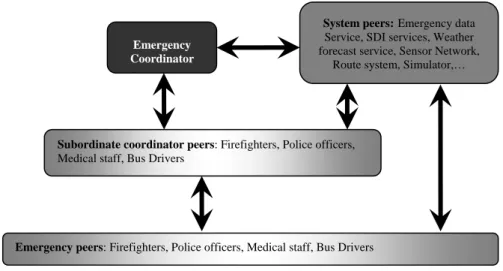
Figure 1: Schematic view of involved peers and main interactions in the evacuation plan
Figure 1 shows a schematic view of the involved peers together with the flow of the main interactions (arrows) during the evacuation plan in the selected eResponse coordination activity. The emergency coordinator evaluates the information collected by the peers and the system services, and propagates its plans to the subordinate coordinators, who are responsible for acting on the plan by distributing plans/sub-plans to each organization or group involved in the crisis management. In our use case, the evacuation plan is enacted by the emergency coordinator, by (i) propagating the alarm to the bus drivers and assign them the appropriate destination; (ii) propagating the alarm to the subordinate coordinators; (iii) sending the evacuation alarm and information to the citizens; (iv) continuously monitoring the crisis information from all available sources (e.g. sensors, institutional peers, volunteers, citizens) and taking appropriate actions.
THE E-RESPONSE SYSTEM
Since emergency situations are of a critical nature, it is essential that any infrastructure, and related processes, to assist the emergency response is fully tested and evaluated outside that situation. We have therefore developed a simulator in order to demonstrate and evaluate our approach within a simulation, so as to estimate how it could perform in a genuine emergency. The eResponse system we are developing is used in our current work:
(1) to model and execute interactions of peers involved in an emergency response activity, whether individuals, institution peers, sensors, web services or others;
(2) to provide feedbacks about the environment at appropriate moments, in a way that mirrors the real world (for example, a peer attempting to take a road will be informed at that moment if that road is blocked, and it can then share this information with other peers through the network).
(3) to visualize and analyze a simulated coordination task through a Graphical User Interface (GUI).
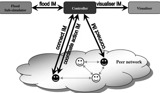
The eResponse system is composed of two major components: the eResponse simulator and the peer network. Figure 2 sketches the overall architecture of the system. Examples of peer types have been discussed in the previous section (i.e. Figure 1). In the next two subsections, we will focus on the eResponse simulator and the peer network, respectively.
The eResponse Simulator
The simulator is composed of three peers: the controller, the flood sub-simulator, and the visualiser (see Figure 2). The controller is the core of the simulator: it drives the simulation cycles. The controller has one main goal: to keep track of the current state of the world. In order to achieve that, the controller needs to know what changes are happening to the world and update its state accordingly.
Flood
Sub-simulator Controller Visualiser
Peer network
Figure 2: The eResponse system’s architecture
Of course, after updating its state, it should inform the relevant peers of these changes as well. The goal of the flood simulator is to simulate the flood. It is composed of a set of predefined equations that define how the flood evolves with time. The goal of the visualiser is to simply visualise what is happening in the flood area. Simulation is then divided into cycles, which are driven by the controller. The steps of one simulation cycle are: 1. The controller shares the initial topology of the world with others simulator peers: the flood sub-simulator
and the visualiser. The controller receives also information about the changes that happened to the world: a. It receives the flood changes from flood sub-simulator
b. It receives other changes from the peers in the peer network that caused these changes (and verifies their validity)
2. The controller sends information about the changes that happened in the world: c. It sends a list of all the changes to the simulator’s visualiser
d. It sends changes that occurred in a peer’s vicinity to each peer in the peer network 3. The controller updates the time step, and repeats by going back to step 1
The flow of the interactions between the controller and other peers is also depicted in Figure 2. Each black arrow represents a different interaction model, which also represents the flow of information between peers. For example, the flood interaction model “flood IM” is used to allow the flood sub-simulator to communicate with the controller, sending it flood changes at each time step. Since the above architecture is modular, it is reasonably easy to add as many emergency sub-simulators (e.g., landslides, earthquake, volcanic eruption, etc.) as needed: each implemented sub-simulator would, in fact, communicate with the controller through an interaction model nearly identical to the one mentioned before and the controller would be enhanced to handle the new types of emergency data.
Note that the controller (or the simulator in general) does not interfere or help coordinate peer’s actions in the peer network. It is simply used to simulate the real world. For instance, peers cannot ask the simulator questions about the world, such as where the location of something is or what the flood level at a given point is. Nevertheless, in the real world, peers (whether humans or sensors) are able to sense certain things in their vicinity. Therefore, in our simulation, this information will be provided by the controller. At every time step, the controller sends sensory info for each connected peer through the “connect” interaction model. Also, the real world usually prevents humans (or even sensors) from performing certain unrealistic actions. For example, one person may try to drive a car in a flooded road, but will fail even if he insisted. Usually, the rules of physics of the real world prevent such unrealistic actions. Again, in our simulation, the controller will verify whether certain actions are legal or not before they are performed, and if a certain action is illegal, the peer is informed of the reason of failure. This is done through the “coordinate action” interaction model (see Figure 2). Note that any peer that either needs to perform an action (such as a police man closing a road) or needs to receive sensory info about its vicinity (such as a sensor) needs to be connected to the simulator. We call these peers physical peers. They are represented as black faces in the peer network of Figure 2. Of course, not all peers need to connect to the controller. Just like in real life, non physical peers, such as a web service that provides information about the weather, do not need to communicate with the controller but with other peers in the peer network (such as a sensor, a human user, ect.). Non physical peers are represented as white faces in the peer
network of Figure 2. Please note, that in the current system, the existence and regular functionality of communication channels among peers is assumed. More complex situations in which some communications are degraded, could be in principle included and emulated in the flood sub-simulator – for instance following an implementation similar to the OCTOPUS Virtual Environment (D’Aprano, de Leoni and Mecella, 2007) - but are not included in the present prototype.
For completeness, the paper is complemented - in this technical report - by two appendixes, which present and analyse the technical details of the developed interaction models: (i) for the eResponse simulator (Appendix 1) and (ii) for the selected use case, i.e .the evacuation plan (appendix 2).
The Peer network
In this section we first describe the Lightweight Coordination Calculus (LCC), that is, the communication language employed to implement the interactions among peers acting in our Peer-to-Peer (P2P) network. After briefly introducing it, we then report a selected coordination problem taken from the scenario depicted in the previous section, and explain in some details the interaction models which can be derived to describe it. Finally, we show a preliminary prototype which has been implemented to execute and analyze the evolution of the interactions within a peer-network.
Introduction to LCC
LCC is a protocol language used to describe interactions among distributed processes, e.g., agents, web services (Robertson, 2004-1; Robertson, 2004-2). LCC was designed specifically for expressing P2P style interactions within multi-agent systems, i.e., without any central control; therefore, it is well suited for modeling coordination of software components running in an open environment. Its main characteristics are flexibility, modularity and the neutrality to the distributed communication infrastructure.
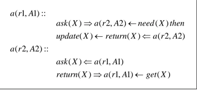
Interactions in LCC are expressed as the message passing behaviours associated with roles. The most basic behaviours are to send or receive messages, where sending a message may be conditional on satisfying a constraint (precondition) and receiving a message may imply constraints (postcondition) on the agent accepting it. As an example, a basic LCC interaction is shown in Figure 3 where double and single arrows indicate respectively message passing and constraints to satisfy:
) ( ) 1 , 1 ( ) ( ) 1 , 1 ( ) ( ) 2 , 2 ( ) ( ) ( ) ( ) 2 , 2 ( ) ( :: ) 2 , 2 ( :: ) 1 , 1 ( X get A r a X return A r a X ask A r a X return X update then X need A r a X ask A r a A r a ← ⇒ ⇐ ⇐ ← ← ⇒
Figure 3: Basic LCC interaction
According to the interaction shown in Figure 3, the agent A1 playing the role r1 verifies if it needs the info X (precondition need(X)); if yes, A1 asks for X to the agent A2 playing the role r2 by sending the message ask(X). A2 receives the message ask(X) from A1 and then get the info X (precondition get(X)) before sending back a reply to A1 through the message return(X). After having received the message return(X), A1 updates its knowledge (postcondition update(X)).
The constraints embedded into the protocol express its semantics and could be written as first-order logic predicates (i.e., in Prolog) as well as methods in an object-oriented language (i.e., in Java). Furthermore, these constraints could hide simple functionalities (i.e., provided by web services) as well as very complex AI algorithm. This is the characteristic of modularity previously mentioned that allow the separation of the protocol and the agent or service engineering. While performing the protocol, peers can therefore exchange messages, satisfy constraints before (after) messages are sent (received) and jump from one role to another so that a flexible interaction mechanism is enabled still following a structured policy, this being absolutely necessary for team-execution of coordinated tasks.
Firefighter Coordinator Firefighter Route Service Simulator
Send directive
Send route
Plan next move
Perform move
Check move feasibility Disconfirm destination
Assign new destination
Request route Prepare to move to destination
[ route ] [ empty route ]
[ feasible move ]
[ reach destination ] [ unfeasible move ]
[ doesn't reach destination ] Assign destinations
Confirm destination
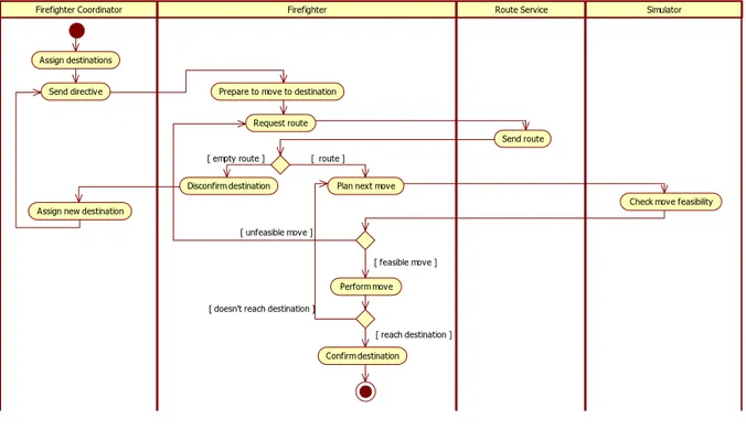
Figura 4: Activity diagram of the coordination task “Go to Destination”
Flooding evacuation use case and selected examples of Interaction Models
We designed and implemented a sub-scenario where different participating actors, having different roles, coordinate each other and rely on existing service components. This scenario is currently running on a Prolog based LCC parser engine and on a local P2P network. It constitutes a simulated scenario where peers are either emergency peers, that is, agents acting on behalf of human emergency personnel, or system peers, that is, digital services providing information that are essential for coordinated task execution.
Our sub-scenario - of the overall scenario flooding evacuation use case - is related to the phase where an emergency coordinator (the firefighter coordinator in this case) sends a directive to its organizational peers (firefighters) that have to accomplish it. The coordination problem expressed above can be described in a verbose form as follow:
After having found out all the available firefighters, the firefighter coordinator (ffc) assigns to each of them a specific destination; in order to find a route, the firefighter will rely on the route service component whose aim is to provide a suitable path to the requester; the firefighter communicates each action to the simulator which checks the feasibility of the action (i.e., the action of moving could be impossible because a road is blocked); in case of a blocked road the firefighter asks the route service an alternative path (which doesn't contain the blocked road) and keeps trying alternatives till either there are free paths connecting him with the destination or this latter is unreachable; if the firefighter reaches the previously assigned destination he/she will confirm it to the ffc otherwise he/she will inform the chief about the negative result; the ffc will reassign a destination to the firefighter who couldn't reach the previous place.
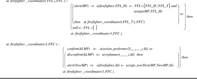
This description can be sketched in a graphical representation such as the activity diagram shown in Figure 4. The diagram shows the workflow related to the coordination task “Go to Destination”. An interaction model - expressed in a compact, formal language such as LCC - can be derived either from the narrative description above or from an activity diagram. In this last case, the conversion could be done manually or automatically As examples of the implementation and usage of the interaction model language, Figures 5, 6 and 7 show some excerpts of LCC code related to the firefighter coordinator, firefighter and route service roles respectively. It is worth noticing here that the LCC code presented in this paper is part of the code needed to run the interaction. The whole code is more lengthy since it entails also the role of the simulator peer and its interactions with the network peers. However, for our purposes here - to indicate how to model the possible interactions among the network peers – we restrict our description to these excerpts.
i. Fire-fighter coordinator
The firefighter coordinator, FFC, initiates the coordination task by entering the role firefighter_coordinator. According to this role a list of available firefighters, FFL, must be retrieved in order to send an alert message to each of them. The role involves a recursion over the list FFL so that a destination meeting point (MP) can be assigned and an alert message can be sent to each firefighter FFL_H, in FFL. After having sent the messages to all the firefighters, the FFC assumes the role firefighter_coordinator3. Here the FFC receives a confirmation (or disconfirmation) of reached (not reached) destination MP from a given firefighter Id (in Figure 5 ‘action_performer2’ and ‘replanner’ are roles assumed by the firefighter role) and the role recurses. If a disconfirmation is received, the FFC assigns to the firefighter Id a new destination – NewMP - which is then embedded in the alert message sent back.
[
]
[ ]
). FFC , 3 r coordinato _ r firefighte ( a then Id) NewMP, Dest(MP, assign_new Id) ter, a(firefigh P) alert(NewM then Id) _), _, r(_, a(replanne MP) (Id, disconfirm or Id) _), _, _, _, erformer2( a(action_p MP) , confirm(Id :: ) FFC , 3 r coordinato _ r firefighte ( a ). FFC , 3 r coordinato _ r firefighte ( a then FFL null or FFC FFL r coordinato r firefighte a then FFL_H) assign(MP, and FFL_T | FFL_H FFL FFL_H) ter, a(firefigh alert(MP) :: ) FFC ), FFL ( r coordinato _ r firefighte ( a ⎟ ⎟ ⎟ ⎟ ⎟ ⎠ ⎞ ⎜ ⎜ ⎜ ⎜ ⎜ ⎝ ⎛ ⎟ ⎟ ⎟ ⎠ ⎞ ⎜ ⎜ ⎜ ⎝ ⎛ ← ⇒ ⇐ ⇐ ⎟⎟ ⎟ ⎟ ⎟ ⎟ ⎟ ⎠ ⎞ ⎜⎜ ⎜ ⎜ ⎜ ⎜ ⎜ ⎝ ⎛ = ← ⎟ ⎟ ⎟ ⎟ ⎟ ⎠ ⎞ ⎜ ⎜ ⎜ ⎜ ⎜ ⎝ ⎛ ) ), _ ( _ ( = ← ⇒ ΤFigure 5: LCC fragment for the firefighter coordinator role
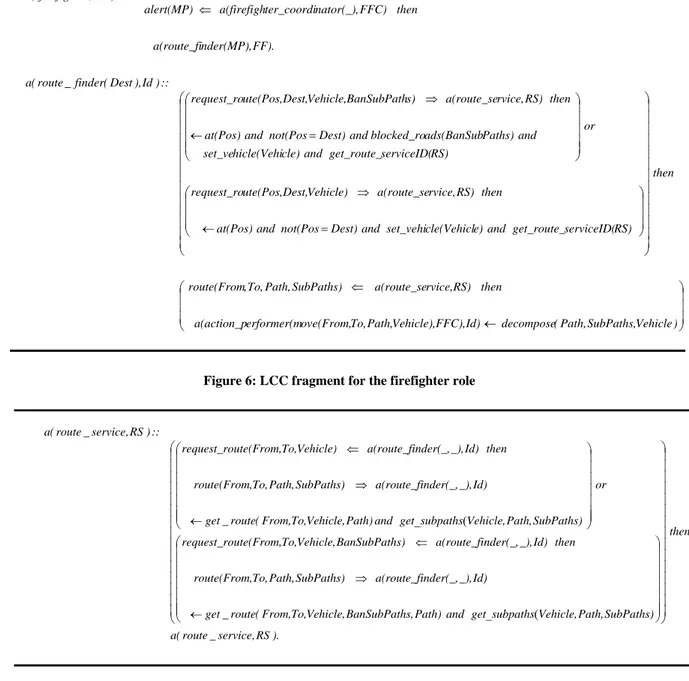
ii. Fire-fighters
Each firefighter, FF, receives from the firefighter coordinator, FFC, an alert message stating that the destination MP has to be reached. Once the message is received, the firefighter, FF, assumes the role of
route_finder. If the firefighter, FF, is not yet at the location Dest that must be reached, a vehicle will be
needed together with the name of a digital service able to provide a route. A message for requesting a route between two locations (Pos and Dest) is then sent to the route service RS. Once the firefighter FF receives the requested path together with its sub-paths through a message sent by the route service RS, he/she stores the path in its local memory and assumes the role action_performer in order to communicate the move action to the simulator which in turn will check its feasibility (more details in the activity diagram in figure 4).
iii. Route Service
The route service, RS, after having received a route request from a route finder Id, selects a path from node
From to node To, splits the path in sub-paths and sends them back to the route finder Id. The route service
role then recurses to be able to accept other requests. The route service can receive two types of messages from a route finder:
A message asking for a path from A to B (a vehicle is also specified);
A message asking for a path from A to B (a vehicle is also specified) not including certain sub-paths (i.e., the blocked subpaths).
⎟ ⎟ ⎟ ⎠ ⎞ ⎜ ⎜ ⎜ ⎝ ⎛ ← ⇐ ⎟ ⎟ ⎟ ⎟ ⎟ ⎟ ⎟ ⎟ ⎟ ⎟ ⎟ ⎟ ⎟ ⎠ ⎞ ⎜ ⎜ ⎜ ⎜ ⎜ ⎜ ⎜ ⎜ ⎜ ⎜ ⎜ ⎜ ⎜ ⎝ ⎛ ⎟ ⎟ ⎟ ⎠ ⎞ ⎜ ⎜ ⎜ ⎝ ⎛ = ← ⇒ ⎟⎟ ⎟ ⎟ ⎟ ⎠ ⎞ ⎜⎜ ⎜ ⎜ ⎜ ⎝ ⎛ = ← ⇒ ⇐ ) Vehicle , SubPaths , Path ( decompose Id) FFC), Vehicle), Path, To, ove(From, erformer(m a(action_p then RS) rvice, a(route_se SubPaths) Path, To, , route(From then RS) serviceID( get_route_ and e) cle(Vehicl set_vehi and Dest) not(Pos and at(Pos) then RS) rvice, a(route_se Vehicle) Dest, ute(Pos, request_ro or RS) serviceID( get_route_ and cle) hicle(Vehi set_ve and Paths) ads(BanSub blocked_ro and Dest) not(Pos and at(Pos) then RS) rvice, a(route_se s) BanSubPath Vehicle, Dest, ute(Pos, request_ro :: ) Id ), Dest ( finder _ route ( a FF). nder(MP), a(route_fi then FFC) nator(_), ter_coordi a(firefigh alert(MP) :: ) FF , r firefighte ( a
Figure 6: LCC fragment for the firefighter role
). RS , service _ route ( a then SubPaths) Path, Vehicle, subpaths get and Path) s, BanSubPath Vehicle, To, From, ( route _ get Id) _), nder(_, a(route_fi SubPaths) Path, To, , route(From then Id) _), nder(_, a(route_fi s) BanSubPath Vehicle, To, ute(From, request_ro or SubPaths) Path, Vehicle, subpaths get and Path) Vehicle, To, From, ( route _ get Id) _), nder(_, a(route_fi SubPaths) Path, To, , route(From then Id) _), nder(_, a(route_fi Vehicle) To, ute(From, request_ro :: ) RS , service _ route ( a ⎟ ⎟ ⎟ ⎟ ⎟ ⎟ ⎟ ⎟ ⎟ ⎟ ⎟ ⎟ ⎟ ⎟ ⎟ ⎠ ⎞ ⎜ ⎜ ⎜ ⎜ ⎜ ⎜ ⎜ ⎜ ⎜ ⎜ ⎜ ⎜ ⎜ ⎜ ⎜ ⎝ ⎛ ⎟⎟ ⎟ ⎟ ⎟ ⎟ ⎟ ⎠ ⎞ ⎜⎜ ⎜ ⎜ ⎜ ⎜ ⎜ ⎝ ⎛ ( _ ← ⇒ ⇐ ⎟⎟ ⎟ ⎟ ⎟ ⎟ ⎟ ⎠ ⎞ ⎜⎜ ⎜ ⎜ ⎜ ⎜ ⎜ ⎝ ⎛ ( _ ← ⇒ ⇐
Figure 7: LCC fragment for the route service role
Preliminary Prototype
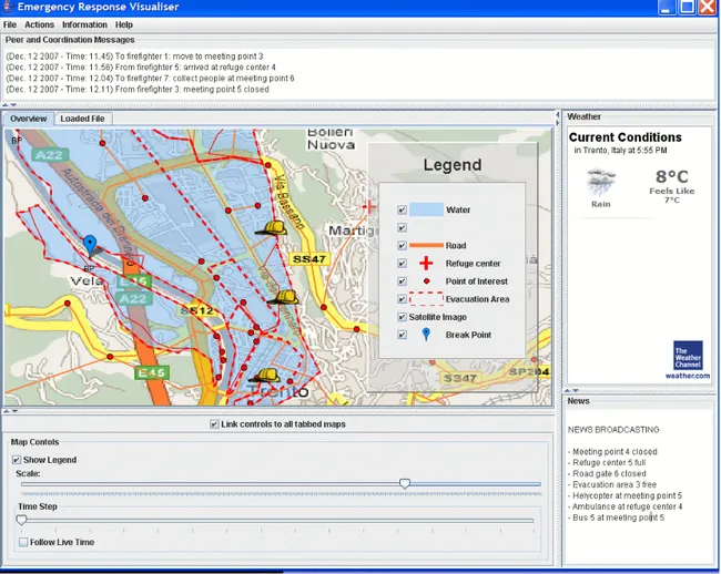
We developed an initial prototype in which the coordination activities between the network peers can be executed, visualised and analysed to evaluate the effectiveness of the LCC protocol. In our first prototype, the ongoing simulation and the resulting movements of the emergency peers are visualized through a GUI (see Figure 8). The GUI is a draft version of the control panel used by the emergency coordinators. Through the emergency GUI, users can visualize the map of the emergency situation.
Figure 8: The emergency GUI
The map shows static geographic datasets (topographic map, probable flooding areas, escape roads, meeting points, refuge centers, sensor network) as well dynamic datasets (the figure shows the position of the firefighters involved in the simulation). Moreover, through the GUI, the emergency coordinators can perform actions (enact the emergency plan, recall digital services, change the map legend, search for other GIS datasets, send statements to the emergency peers, etc) as well as ask for information about the emergency situation (i.e., evacuated people, list of the emergency peers, blocked roads, situation of the meeting points and of the refuge centers, etc). The main components of the GUI are:
The main menu in the upper part of the GUI
The peer and coordination messages frame: it shows the messages exchanged between the coordination peer and the emergency peers (different for each peer)
The weather forecast frame: useful to analyze the current weather conditions
The news frame: it shows the general information about the emergency situation (identical for all the peers) The map frame: it shows, together with a real map of Trento and some static interesting points
(coordination center, the meeting points, the refuge points, etc.), the movement of the peers during a simulated coordination task.
We have run several simulations involving the peers types and the interactions described previously. In the one visualize in Figure 8, we have set 4 emergency peers (1 firefighter coordinator and 3 firefighters), 1 digital service (the route service) and the simulator peer; the coordination task was to follow a directive sent by the firefighter coordinator to its personnel. The directive consisted in moving to a given destination. We set 3 different destinations (meeting points) for each firefighter and initially fixed some specific roads as blocked. First, all the firefighters were at the same location, that is, the coordination center. By running the simulation we obtained three different behaviours for the three firefighters:
1. one firefighter reached the assigned destination without any problem;
2. one firefighter reached the destination after having tried more than one alternative path;
3. the third firefighter couldn’t reach the assigned destination and, as a result, was redirected to a second location.
Figure 8 shows a snapshot of the evolution of the simulated “Go To Destination” process. With these preliminary experiments we give an initial qualitative evaluation of the suitability of the protocol language to handle processes involving both agents and digital services. The modelling of interactions in the LCC language allows us to structure the coordination task still maintaining some adaptability, this latter being intended as the capability to entail situations which are not known a priori (i.e., the blockage state of the road can change over time ).
A more comprehensive evaluation would entail two dimensions: (a) a qualitative validation of the simulation system and the interaction models by involving the local institutions working in crisis management. Expert people in the field can give useful feedbacks by saying how well the simulations reflect the actual plans. Moreover, the simulations can give useful hints to the experts by showing possible scenarios they didn’t foresee, since the plan is actually written on paper and never tried in real situations. In this case, the simulation system could act as a training system for the experts; (b) an evaluation of how the approach scales. Such evaluation can be done by simulating a large number of peers participating in many interactions; measures on performance (e.g. response time) could be adopted.
RELATED WORK
In the present work, we show how an interaction oriented approach might be adopted to handle the coordination problems arising when multiple agencies need to collaborate on emergency response management. Our approach envisages a twofold perspective: one is related to the provision of a controlled but chaotic environment in which to study the effectiveness of interaction models in coordinating agents in real time. Here the emphasis is on a Multi-Agent simulation as a testbed for investigating, along with the validity of interaction models, the impact of a P2P infrastructure in emergency response. The idea to apply multi-agent models for such purposes is not new since a number of complex Multi-Agent Systems (MAS) simulators are under development (Murakami, Minami, Kawasoe and Ishida, 2002; Kanno, Morimoto and Furuta, 2006; Massaguer, Balasubramanian, Mehrotra and Venkatasubramanian, 2006; Robocup-Rescue, 2005).
The second perspective, the one distinctive to our work, is concerned with the peculiarity of an agent protocol language (LCC in our case) specifically designed for expressing interactions in a P2P fashion, which we use to provide a mechanism for knowledge coalition formation and Web service composition, following the approach in (Li and Robertson, 2005; Robertson et al, 2007; Walton, 2005). Here the emphasis is on MAS techniques for inter-operability and coordination tasks employed in P2P architecture. The combination of the two perspectives has the potential to handle the dynamic and distributed aspects of emergency situations: in such scenarios, a P2P architecture is always preferred over a centralised client/server one since it allows the involvement of a large number of participants interacting in a distributed and decentralised manner. We describe collaboration between these participants through the specification of a message passing behaviour for each service involved.
Related research works are either specifically devised for the emergency management area or focused more on the architectural aspect. In particular CASCOM1 , WORKPAD2, EGERIS3, EUROPCOM4 , POMPEI5, POPEYE6 , WIN7 are few such projects. For example, in the CASCOM project (Context-Aware Business Application Service Coordination in Mobile Computing Environments) an intelligent agent-based peer-to-peer (IP2P) environment is under development (Helin, Klusch, Lopes, Fernandez, Schumacher, Schuldt, Bergenti and Kinnunen, 2005). Here, the service coordination mechanism relies on Semantic Web technologies, such as OWL-S and WSMO, rather than an explicit lightweight protocols. Also, the WORKPAD project aims at designing and developing an innovative software infrastructure (software, models, services, etc.) for supporting collaborative work of human operators in emergency/disaster scenarios (Mecella, Catarci, Angelaccio, Buttazzi, Krek , Dustdar and Vetere, 2006). A set of front-end peer-to-peer communities providing services to human workers, mainly by adaptively enacting processes on mobile ad-hoc networks, is part of the system developed (de Leoni De Rosa and Mecella, 2006). Each community is lead by a super-peer, the only peer managing workflow composition and coordination in an adaptive manner. In this case, a mechanism based on our approach would allow each peer to execute, and eventually modify, the workflow, thanks to the sharing of the multi-agent protocol. The work in (Li et al, 2005) also represents an effort in this direction: in this case the approach has been applied directly to business modelling. The method has proved to be promising also in the field of e-Science (Walton and Barker, 2004).
1 http://www.ist-cascom.org 2 http://www.workpad-project.eu/description.htm 3 http://www.egeris.org 4 http://www.ist-europcom.org 5 http://www.pompei-eu.com 6 http://www.ist-popeye.org 7 http://www.win-eu.org
CONCLUSIONS AND FUTURE WORK
The purpose of this paper is to show how an approach based on interaction models sharing through a P2P network can be applied successfully to support coordination problems in the context of emergency response management.
Currently, our eResponse system is running on a Prolog based LCC engine. The current system is basic in the sense that it simply provides means to execute LCC interaction models. However, to run an interaction model, the peer should know which interaction model it wants to execute and with which peers it will be interacting. This and more, is under development in the European project OpenKnowledge8: the project provide a unifying framework based on interaction models that are mobile among peers. The developing OpenKnowledge platform (Siebes at al, 2007) provides means for us to move to a more dynamic system: peers will be able to use discovery services to search for appropriate interaction models, look for suitable peers, and make use of some other important functionalities, such computing trust, verifying interaction models, providing automated assistance for generation of LCC, etc.
But how does this help our (flood) emergency scenario? Let us consider the interaction model of previous section. A more dynamic version of this scenario would be to have a firefighter coordinator asking firefighters to perform certain actions. However, instead of specifying how the firefighter will get the path between two nodes, we may keep this a general constraint to be solved by the peer. At runtime, the peer may then succeed in satisfying the constraint either by consulting its own knowledge base or by using some interaction model to communicate with others in order to achieve its goal. It could then use some discovery service of the OpenKnowledge system to search for suitable interaction models and peers. One solution could be to ask a route service, another solution could be to consult peers in that vicinity.
For emergency scenarios, this ultra dynamic P2P approach is crucial since it implies that even if parts of the system fails, for some reason or another, peers will still be able to find other methods for achieving their critical goals. In the near future, we will address a number of issues and limitations of the current system, namely improved interaction model design, use of appropriate workflow technology and more dynamic interactions. ACKNOWLEDGMENTS
This work has been supported by the OpenKnowledge project (FP6-027253).
The scenario and flooding use case is based on extensive interviews with involved local authorities and analysis of current local emergency plans. We want to thank here the availability of ing. Mario Perghem Gelmi, Marco Bommassar, dott. Federico Bortolotti and ing. Mirko Gasperotti, geom. Cinelli and dott. Michele Zanolli. We want to thank David Dupplaw for the development of the emergency GUI. We acknowledge Fausto Giunchiglia and Dave Robertson for comments and advice on the eResponse system architecture.
REFERENCES
1. D’Aprano, F., de Leoni, M. , Mecella, M., “Emulating Mobile Ad-hoc Networks of Hand-held Devices. The OCTOPUS Virtual Environment”. In Proc. of the ACM Workshop on System Evaluation for Mobile Platform: Metrics, Methods, Tools and Platforms (MobiEval) at Mobisys 2007, Puerto Rico 11-14 June 2007
2. de Leoni M., De Rosa F., Mecella M.. “MOBIDIS: A Pervasive Architecture for Emergency Management”. Proceedings of the 15th IEEE International Workshops on Enabling Technologies: Infrastructure for Collaborative Enterprises, pp. 107-112, 2006.
3. Helin, H.; Klusch, M.; Lopes, A.; Fernandez, A.; Schumacher, M.; Schuldt, H.; Bergenti, F.; Kinnunen, A.: Context-aware Business Application Service Co-ordination in Mobile Computing Environments. In: AAMAS05 workshop on Ambient Intelligence - Agents for Ubiquitous Computing, 2005.
4. Kanno T., Morimoto Y., Furuta K.. “A distributed multi-agent simulation system for the assessment of disaster management systems”, International Journal of Risk Assessment and Management 2006 - Vol. 6, No.4/5/6 pp. 528 - 544
5. Li G., Robertson D., and Chen-Burger J.. “A novel approach for enacting distributed business workflow on a peer-to-peer platform”. In Proceedings of the IEEE Conference on E-Business Engineering, Beijing, 2005.
6. Marchese M., Vaccari L., Trecarichi G., Osman N. and McNeill F. “eResponse Simulation system”. Technical Report DISI-08-15, University of Trento, http://eprints.biblio.unitn.it/, 2008.
8 OpenKnowledge Project: www.openk.org/
7. Massaguer D., Balasubramanian V., Mehrotra S., Venkatasubramanian N.. “Multi-Agent Simulation of Disaster Response”, ATDM Workshop in AAMAS 2006.
8. Mecella M., Catarci T., Angelaccio M., Buttazzi B., Krek A., Dustdar S., and Vetere G.. “Workpad: an adaptive peer-to-peer software infrastructure for supporting collaborative work of human operators in emergency/disaster scenarios”. In Proceedings of the 2006 International Symposium on Collaborative Technologies and Systems. IEEE Computer Society, 2006.
9. Municipality of Trento. “Civilian emergency plan for the municipality of Trento. Piano di Protezione Civile Comunale contro il Rischio Idrogeologico di Inondazione del Fiume Adige”, 2002.
10. Murakami, Y.; Minami, K.; Kawasoe, T.; Ishida, T. “Multi-agent simulation for crisis management”, Knowledge Media Networking, 2002
11. Provincia Autonoma di Trento. “Provincial and municipal emergency protection guidelines. Linee guida per le attività di previsione, prevenzione, protezione e la pianificazione di protezione civile provinciale e comunale”, 2005.
12. Robertson D. “A lightweight coordination calculus for agent systems”. In Declarative Agent Languages and Technologies, pages 183-197, 2004-1.
13. Robertson D. “A lightweight method for coordination of agent oriented web services”. In Proceedings of AAAI Spring Symposium on Semantic Web Services, California, USA, 2004-2.
14. Robertson D., Giunchiglia F., van Harmelen F., Marchese M., Sabou M., Schorlemmer M., Shadbolt N., Siebes R., Sierra C., Walton C., Dasmahapatra S., Dupplaw D., Lewis P., Yatskevich M., Kotoulas S. , Perreau de Pinninck A., and Loizou A., “Open Knowledge Semantic Webs Through Peer-to-Peer Interaction”, http://www.cisa.informatics.ed.ac.uk/OK/manifesto.pdf, 2006.
15. Robertson D., Walton C., Barker A., Besana P., Chen-Burger Y., Hassan F., Lambert D., Li G., McGinnis J., Osman N., Bundy A., McNeil F. van Harmelen F., Sierra C., and Giunchiglia F.. “Models of interaction as a grounding for peer to peer knowledge sharing”. Advances in Web Semantics, Vol. 1, 2007.
16. Robocup-Rescue Simulation Project. http://www.rescuesystem.org/robocuprescue/, 2005
17. Siebes R., Dupplaw D., Kotoulas S., Perreau de Pinninck A., van Harmelen F., Robertson D., “The OpenKnowledge System: An Interaction-Centered Approach to Knowledge Sharing”, R. Meersman and Z. Tari et al. (Eds.): OTM 2007, Part I, LNCS 4803, pp. 381–390, 2007, Springer-Verlag Berlin Heidelberg 2007
18. Vaccari L., Ivanyukovich A. and Marchese M., "A Web Service Approach to Geographical data distribution among public administrations" in 5th IFIP Conference on e-Commerce, e-Business, and e-Government I3E'2005, Poznan, Poland, October 26-28, 2005
19. Walton C. and Barker A.. “An agent-based e-science experiment builder”. In Proceedings of the 1st International Workshop on Semantic Intelligent Middleware for the Web and the Grid, Valencia, Spain, Aug 2004.
20. Walton C., “Typed Protocols for Peer-to-Peer Service Composition”. Proceedings of the 2nd International Workshop on Peer to Peer Knowledge Management (P2PKM 2005), San-Diego, USA, July 2005.
APPENDIX 1
In what follows, we present the technical details of the simulation cycles and the interaction models used by the simulator peers.
Flood.lcc
This interaction model is used to let the flood sub-simulator inform the controller of the flood changes, which should occur once every simulation cycle. This is depicted as step 1.(a) in the simulation cycle. The interaction model is specified as follows:
a(flood_simulator,FS) ::=
get_topology(URI) <-- initial_topology_source(URI) <= a(controller,C) then a(flood_simulator2(C),FS).
a(flood_simulator2(C),FS) ::=
flood_info(Changes) => a(controller2,C) <-- flood_changes(Changes) then ok <= a(controller3(_,_,_),C) then
a(flood_simulator2(C),FS).
a(controller,C) ::=
initial_topology_source(URI) => a(flood_simulator,FS) <-- get_initial_topology(URI) and flood_simulator(FS) then a(controller2,C) <-- time(Time).
a(controller2,C) ::=
update_flood_changes(Changes) <--
flood_info(Changes) <= a(flood_simulator2(_),FS) then a(controller3(FS,Time,Time2),C) <-- time(Time) then a(controller2,C).
a(controller3(Id,Time,Time2),C) ::=
ok => a(flood_simulator2(_),Id) <-- current_timestep(Time2) and Time2>Time or
a(controller3(Id,Time,Time2),C) <-- sleep(0.1).
The interaction model is initiated by the controller, which plays the role ‘controller’. When the simulation starts, the controller should coordinate the topology of the world with the flood sub-simulator by sending it the topology’s URI. It then takes the role ‘controller2’ to receive the flood changes sent out by the flood sub-simulator at every time-step. However, the controller should ensure that changes are received only once every time-step. Therefore, after receiving the flood changes, the controller takes the role ‘controller3’, which loops finitely often, until the controller enters a new time-step. At that point, it sends an ‘ok’ message to the flood simulator, signaling that further flood changes may now be sent. It then goes back to role ‘controller2’ to receive any further flood changes from the flood simulator.
Note that the flood sub-simulator, playing the role ‘flood_simulator’, works in parallel with the controller. After receiving the topology of the world, it takes the role ‘flood_simulator2’. In this role, the flood sub-simulator computes the flood changes and sends this information back to the controller. It then waits for an ‘ok’ message from the controller before it repeats this all over again.
Coordinate_Action.lcc
This interaction model is used to let the connected physical peers inform the controller of the physical actions they are performing. As mentioned earlier, peers should inform the controller of all their physical actions since these would result in changes in the physical world. Furthermore, it is the controller that would confirm whether an action is currently possible or not. This is depicted as step 1.(b) of the simulation cycle. The interaction model is specified as follows:
a(action_performer(Action,Result),Id) ::= a(action_performer2(C,SubActions,Result),Id)
<-- controller(C) and breakdown(Action,SubActions). a(action_performer2(C,SubActions,FResult),Id) ::= ( action(Action) => a(action_coordinator,C) <-- SubActions=[Action|Tail] then
result(Result) <= a(action_coordinator2(_,_),C) then
( null <-- member(Result,[illegal_action(_),indecipherable(_)]) and FResult=fail
or
a(action_performer2(C,Tail,FResult),Id)
<-- member(Result,[ok]) and performed_action(Action) ) ) or
null <-- SubActions=[] and FResult=success.
a(action_coordinator,C) ::=
action(Action) <= a(action_performer2(_,_,_),Id) then a(action_coordinator2(Action,Id),C) then a(action_coordinator,C). a(action_coordinator2(Action,Id),C) ::= result(Result) => a(action_performer2(_,_,_),Id) <-- update_action_results(Id,Action,Result) or a(action_coordinator2(Action,Id),C) <-- sleep(0.1).
The above interaction model is initiated by any physical peer that needs to coordinate the actions it needs to perform with the controller. The physical peer will be playing the LCC role ‘action_performer’. It initiates this interaction model knowing that ‘Action’ needs to be performed and expecting some ‘Result’ to be returned. It then obtains the Id of the controller it will be communicating with, it breaks down the action into atomic sub-actions, and then takes the role ‘action_performer2’ to coordinate its sub-actions with the controller C.
Note that the physical peer may coordinate one atomic action at a time. Atomic actions are of three categories:
pick, drop, and move. Complex actions will have to be broken into atomic sub-actions before they are
coordinated with the controller. For example, the action of having Peer1 transport object O from Node1 to Node2 is broken down into the following sub-actions:
Peer1 moving to Node1
Peer1 picking object O
Peer1 moving to Node2
Peer1 dropping object O
Also note that move actions may themselves be complex actions that should be broken down into further atomic sub-actions. The only atomic move actions are the actions that allow peers to move between two nodes which are at most 500m away from each other. We assume a peer may move at most 500m per time-step. This allows the controller to keep the motion of peers realistic. For example, you do not want a peer jumping thousands of kilometers while another jumps a few meters.
After taking the role ‘action_performer2’, the physical peer now performs a recursion over the set of sub-actions it needs to perform. For each sub-action, it sends a message to the controller informing it of the action it would like to perform. It then receives a reply from the controller. If the reply is an ‘ok’ message, then it proceeds. However, the reply could also be ‘illegal_action(_)’ or ‘indecipherable(_)’ messages. If such messages are received, then this implies that either the action is not permitted, or the action is not understood by the controller. In either case, the peer cannot perform that action and it quits the coordination of all remaining sub-actions. The result returned in that case is ‘fail’. A ‘success’ result is returned only if all sub-actions have been completed successfully.
The controller, playing the role ‘action_coordinator’, works in parallel with the ‘action_performer’. After receiving an action, it takes the role ‘action_coordinator2’, which computes the result of performing such an action and informs the ‘action_performer’ whether the action may be carried out or not. Due to synchronization
issues, there are strict restrictions by the controller on when actions may be performed. For example, one sub-action may be performed in one time-step. If the controller tries to mark more than one sub-action per one physical peer in one time-step, then the constraint ‘update_action_results(_,_,_)’ will fail, forcing the controller to wait for 0.1 seconds, before it tries again.
Visualiser.lcc
This interaction model is used to let the controller inform the visualiser of all the changes that have occurred in the world at every time-step. This is depicted as step 2.(a) in the simulation cycle. The interaction model is specified as follows:
a(get_visual_changes,V) ::=
get_topology(URI) and start_gui <--
initial_topology_source(URI) <= a(sending_visual_info,_) then
a(get_visual_changes2,V). a(get_visual_changes2,V) ::= update(Time,AllChanges) <--
vis_info(Time,AllChanges) <= a(sending_visual_info2(_),_) then a(get_visual_changes2,V).
a(sending_visual_info,C) ::=
initial_topology_source(URI) => a(get_visual_changes,V) <-- get_initial_topology(URI) and visualiser_id(V) then a(sending_visual_info2(V),C).
a(sending_visual_info2(V),C) ::=
vis_info(Time,AllChanges) => a(get_visual_changes2,V) <-- get_visual_changes(AllChanges) and time(Time) or
a(sending_visual_info2(V),C) <-- sleep(0.1).
The interaction model is initiated by the controller, which plays the role ‘sending_visual_info’. When the simulation starts, the controller should coordinate the topology of the world with the visualiser by sending it the topology’s URI. It then takes the role ‘sending_visual_info2’ to recursively send out the changes that occurred in the world at every time-step. If the controller tries to obtain the changes twice for the same time-step, then the constraint ‘get_visual_changes(AllChanges)’ will fail, forcing the controller to wait for 0.1 seconds, before it tries again. This ensures changes are sent out only once every time-step.
Note that the visualiser, playing the role ‘get_visual_changes’, works in parallel with the controller. After receiving the topology of the world, the visualiser starts its GUI. It then takes the role ‘get_visual_changes2’, where it receives the changes from the controller at every time-step and updates its history accordingly.
Connect.lcc
This interaction model is used to let physical peers connect to the simulator. When connected, they can then receive sensory information about changes in their vicinity, once every time-step. This is depicted as step 2.(b) of the simulation cycle. The interaction model is specified as follows:
The interaction model is initiated by the physical peer that wishes to connect to the controller. The peer plays the role ‘connecting_peer’. If the peer is interested in connecting to the controller, it would obtain its current peer type (such as firefighter, water sensor, etc.), its location, and the controller’s Id. It then sends an ‘exists’ message to the controller informing it of its peer type and location. After that, it receives a ‘connected’ message from the controller confirming its connection, along with the time-step at which the peer has joined. The peer then plays the role ‘connected_peer’, in which it continuously receives sensory information from the controller about objects in its vicinity. Note that at any point, the peer is allowed to exit the simulation by simply sending the ‘exit’ message to the controller. If this happens, then this would break the recursive cycle through which sensory info is received.
Note that the controller, playing the role ‘registrar’, works in parallel with the physical peer. After receiving an ‘exists’ message, it adds the peer to the map and sends back a ‘connected’ message to confirm the connection. It
then plays the role ‘registrar2’, in which it continuously listens for ‘exit’ messages. If an ‘exit’ message is received, then the peer is removed from the map. Otherwise, it plays the role ‘registrar3’ for sending sensory information to the peer about objects in its vicinity. If the controller tries to obtain this sensory information twice for the same time-step, then the constraint ‘send_update_info(Id,Peers,Flood,Danger,Time)’ will fail, forcing the controller to wait for 0.1 seconds, before it tries again. This ensures that sensory information is sent out only once every time-step.
a(connecting_peer,Id) ::=
exists(Id,PeerType,Location) => a(registrar,C)
<-- connect(true, PeerType, Location) and controller(C) then learn(time(TS)) <-- connected(TS) <= a(registrar,C) then
a(connected_peer(C), Id). a(connected_peer(C),Id) ::=
exit(Id) => a(registrar2(_),C) <-- connect(false,_,_) or
( update_info(Info) <-- sensory_info(Info) <= a(registrar3(_),C) then a(connected_peer(C),Id) ).
a(registrar,C) ::=
add_peer_to_sim(Id,PeerType,Location,Time) <--
exists(Id,PeerType,Location) <= a(connecting_peer,Id) then connected(Time) => a(connecting_peer,Id) then
a(registrar2(Id),C). a(registrar2(Id),C) ::=
remove_peer_from_sim(Id) <-- exit(Id) <= a(connected_peer(_),Id) or ( a(registrar3(Id),C) then a(registrar2(Id),C) ). a(registrar3(Id),C) ::= sensory_info([Id,Peers,Flood,Danger,Time]) => a(connected_peer(_),Id) <-- send_update_info(Id,Peers,Flood,Danger,Time) or a(registrar3(Id),C) <-- sleep(0.1).
APPENDIX 2
In what follows, we present the technical details of the interaction models used by the simulator peers in the selected use case, i.e .the evacuation plan. The roles, the supported activities, related messages and the related constrains are detailed in the comments within the code.
StartFE.lcc
This interaction model is used describes how the evacuation plan starts: (1) an emergency coordinator alerts its personnel to go to a specific destination; (2) each personnel member has to find the route to reach the destination and eventually notify the coordinator in case of failure. It has been tested:
// The firefighter coordinator retrieves a list of available firefighters, FFL, in // order to send an alert message to each of them.
a(firefighter_coordinator,FFC) ::=
a(firefighter_coordinator(FFL),FFC) <-- obtainFFList(FFL)
or null.
// The role involves a recursion over the list FFL so that a destination meeting // point (MP) can be assigned and an alert message can be sent to each firefighter // FFL_H, in FFL. After having sent the messages to all the firefighters, the FFC // assumes the role firefighter_coordinator3.
a(firefighter_coordinator(FFL),FFC)::=
(( alert(MP) => a(firefighter,FFL_H) <-- FFL=[FFL_H|FFL_T] and assign_mp(MP,FFL_H) then
a(firefighter_coordinator(FFL_T),FFC) ) or
( null <-- FFL=[] ) ) then a(firefighter_coordinator3,FFC).
// In this role the FFC receives a confirmation (or disconfirmation) of reached // (not reached) destination MP from a given firefighter Id ('action_performer2' // and 'replanner' are roles assumed by the firefighter role) and the role
// recurses. If a disconfirmation is received, the FFC assigns to the firefighter // Id a new destination - NewMP - which is then embedded in the alert message sent // back.
a(firefighter_coordinator3,FFC)::=
( (confirm(Id,MP) <= a(action_performer2(_,_,_,_),Id)) then a(firefighter_coordinator3,FFC) )
or
(disconfirm(Id,MP) <= a(replanner(_,_,_),Id) then
(alert(NewMP) => a(firefighter,Id) <-- assign_newDest(MP,NewMP,Id)) then a(firefighter_coordinator3,FFC) ).
// The firefighter, FF, receives from the firefighter coordinator, FFC, an alert // message stating that the destination MP has to be reached. Once the message is // received, the firefighter, FF, assumes the role of route_finder.
a(firefighter,FF)::=
( alert(MP) <= a(firefighter_coordinator(_),FFC) or
alert(MP) <= a(firefighter_coordinator3,FFC) ) then a(route_finder(MP,FFC),FF) .
// If the firefighter, FF, is not yet at the location Dest that must be reached, a // vehicle will be needed together with the name of a digital service able to // provide a route. A message for requesting a route between two locations (Pos and // Dest) is then sent to the route service RS. Once the firefighter FF receives the // requested path together with its sub-paths through a message sent by the route // service RS, he/her stores the path (together with the subpaths) in its local // memory and assumes the role action_performer in order to communicate the move // action to the simulator which //in turn will check its feasibility
a(route_finder(Dest,FFC),Id) ::=
( request_route(Pos,Dest,Vehicle) => a(route_service,RS) <-- at(Pos) and not(Pos=Dest) and set_vehicle(Vehicle) and
get_route_serviceID(RS) ) then
(route(From,To,Path,SubPaths) <= a(route_service,RS) then a(action_performer(move(From,To,Path,Vehicle),FFC),Id)
<--store(Path,SubPaths,Vehicle)).
// This role is entered by the firefighter when the simulator sends an
// illegal_action as a result. It is similar to the previous role except for the // fact that
// - a list of banned subpaths - BanSubPaths - is sent to the route service // - a disconfirmation is sent to the coordinator if no free paths leads to the // destination.
// Note: in the future this role will be embedded in the "route_finder" role. a(replanner(S,OldDetails,FFC),Id) ::=
( request_route(Location,To,V,BanSubPaths) => a(route_service,RS)
<-- at(Location) and get_final_location(OldDetails,To) and
get_vehicle(OldDetails,V) and get_BanSubPaths(BanSubPaths) and get_route_serviceID(RS) ) then
(route(From,To,Path,NewDetails) <= a(route_service,RS) then ( a(action_performer(move(From,To,Path,V),FFC),Id)
<-- Path = [H|T] and store(Path,NewDetails,V) ) or
( (disconfirm(Id,To) => a(firefighter_coordinator3,FFC) <-- Path=[]) then
a(firefighter,Id) )).
// The route service, RS, after having received a route request from a route finder // (or replanner) Id, selects a path from node From to node To, split the path in // sub-paths and sends them back to the route finder Id. The route service role // then recurses to be able to accept other requests. The route service can receive // two types of messages from a route finder:
// - A message asking for a path from A to B (a vehicle is also specified); // - A message asking for a path from A to B (a vehicle is also specified) not // including certain sub-paths (i.e., the blocked subpaths).
a(route_service,RS)::=
( request_route(From,To,Vehicle) <= a(route_finder(_,_),Id) then (route(From,To,Path,SubPaths) => a(route_finder(_,_),Id)
<-- get_route(From,To,Vehicle,Path) and get_subpaths(Vehicle,Path,SubPaths)) then a(route_service,RS))
or
( request_route(From,To,Vehicle,BanSubPaths) <= a(replanner(_,_,_),Id) then (route(From,To,Path,SubPaths) => a(replanner(_,_,_),Id)
<-- get_route(From,To,Vehicle,BanSubPaths,Path) and get_subpaths(Vehicle,Path,SubPaths))
then a(route_service,RS)).
// The following code is needed when a peer send an action to the simulator's // controller. Note that this is an adaptation of the interaction model // ”Coordinate_Action.lcc”. In the future there won’t be the need for this // adaptation and the “Coordinate_Action.lcc” should remain unmodified and valid // for every protocol containing interactions with the simulator.
a(action_performer(Action,FFC),Id) ::=
a(action_performer2(S,Details,Details,FFC),Id) <-- simulator(S) and breakdown(Action,Details). a(action_performer2(S,OldDetails,Details,FFC),Id) ::=
( Action => a(action_coordinator,S) <-- Details=[Action|Tail] then Result <= a(action_coordinator,S) then
( a(replanner(S,OldDetails,FFC),Id)
<-- member(Result,[illegal_action(_),indecipherable(_)]) and update_BanSubPath(Action)
or
a(action_performer2(S,OldDetails,Tail,FFC),Id)
<-- member(Result,[ok,pick,drop]) and performed_action(Action))) or
or
(action_completed => a(action_coordinator,S) <-- Details=[] then (confirm(Id,To) => a(firefighter_coordinator3,FFC)
<-- get_final_location(OldDetails,To) and update_position(To))).
a(action_coordinator,S) ::=
(action_completed <= a(action_performer2(_,_,_,_),Id)) or
( update_action_results(Id,Action,Result)
<-- Action <= a(action_performer2(_,_,_,_),Id) then Result => a(action_performer2(_,_,_,_),Id) then
Reconnaissance.lcc
This interaction model describes the phase during which an emergency peer (firefighter) needs to close a meeting point due to the increasing level of water measured at that meeting point and its neighbourhood. It has not been tested yet. The interaction model is specified as follows:
// The firefighter first measures the water level (WL_local) at the meeting point // (MP) and then ask its coordinator to give details on the water level at the // closest areas (WL_adj_nodes). Based on this info, a parameter (Criticality) is // computed in order to decide if it is the case to close the meeting point or not. // If the MP is closed a message is sent to the coordinator.
a(firefighter,FF)::=
update&request_WL_info(MP, WL_local) => a(firefighter_coordinator,FFC)
<-- at(MP) and measure_local_WL(MP, WL_local) and get_coordinator_ID(FFC) then emergency_WL_info(MP, WL_adj_nodes) <= a(firefighter_coordinator,FFC) then
null <- compute(WL_local, WL_adj_nodes, Criticality) then
(a(perfom(close(MP)),FF) <- greater(Criticality,MaxCriticality) then update_on_MP_state(closed) => a(firefighter_coordinator,FFC))
or
a(firefighter,FF).
// The firefighter coordinator receives a message from the firefighter to update // info on water level at meeting point MP and to send info on water levels at its // adjacent points. The coordinator can also receives an
// update_on_MP_state(closed)" message from the firefighter. a(firefighter_coordinator,FFC)::=
((update&request_WL_info(MP, WL_local) <= a(firefighter,FF) then emergency_WL_info(MP, WL_adj_nodes) => a(firefighter,FF)
<-- update_WL_info(MP,WL_local) and gather_WL_adj_area(MP, WL_adj_nodes)) or
update_on_MP_state(closed) <= a(firefighter,FF) ) then a(firefighter_coordinator,FFC).
Census.lcc
This interaction model is used when an emergency peer registers info on people present at a certain location into a database. It has not been tested yet. The interaction model is specified as follows:
// The emergency peer enters this role to obtain the info (Name Type, Location, // // etc.) related to a person and to send a relative message to the dbcurator (the // peer who actually will store the info into the DB). A success (failure) message // is received if things went well (wrong)
a(censuscurator, ID1)::=
update(Name,Type,Location,GPS,Status,Notes) => a(dbcurator, ID2) <-- obtain(List, Name,Type,Location,GPS,Status,Notes) then success(Id) <= a(dbcurator, ID2)
or
(failure(Msg) <= a(dbcurator, ID2) then null <- proceed(Msg))
// The peer who stores info into a DB enters this role. a(dbcurator, ID2)::=
update(Name,Type,Location,GPS,Status,Notes) <= a(censuscurator, ID1) then success(Id) => a(censuscurator, ID1)
<-- updateDb(Name,Type,Location,GPS,Status,Notes,Id) or