Università Politecnica delle Marche
Corso di Dottorato in Ingegneria Civile, Ambientale, Edile e Architettura Curriculum in Ingegneria Civile, Ambientale, Edile e Architettura ---
Experimental and numerical study on the
full scale behaviour of micropiles under
lateral loading
Ph.D. Dissertation of:
Maria Chiara Capatti
Advisor:
Prof. Luigino Dezi
Curriculum supervisor:
Prof. Stefano Lenci
Università Politecnica delle Marche
Dipartimento di Ingegneria Civile, Edile, Architettura Via Brecce Bianche — 60131 - Ancona, Italy
Acknowledgements
I’d like to express my deep gratitude to Alseo srlu, based in Osimo (AN), for having provided the micropiles and the technical support during all the experimental study; the kindness of Marco Valori, who granted the space for the tests, and the tireless efforts of geologists L. Del Maschio and S. Sanchi, are also deeply acknowledged.
The precious reading of the thesis reviewers, Profs. Francesco Silvestri and Daniele Zonta, has been truly appreciated.
I’m sincerely grateful to Francesca Dezi for her guidance throughout those years, and I wish to thank all the staff of department DICEA for the help, the advices and the suggestions provided along the way.
Finally, the most heartfelt acknowledgment is forwarded to my parents, for their constant love, support and encouragement.
Contents
Acknowledgements ... iii Contents... v List of Figures ... ix List of Tables... xv Abstract ... 1 Sommario ... 3 Chapter 1. Introduction ... 5 1.1. Problems Statement ... 5 1.2. Thesis Objectives... 91.3. Organization of the thesis ... 9
Chapter 2. Soil Structure Interaction ... 11
2.1. Introduction ... 11
2.1.1. Direct approach... 12
2.1.2. Substructure approach... 12
2.2. Review of models for Soil Pile Structure Interaction ... 14
2.2.1. Beam on Elastic Foundation Method... 14
2.2.2. Elastic Continuum Method ... 17
2.2.3. Finite Element Method Approach... 20
2.3. Pile groups effects ... 21
2.3.1. Approximate methods for the interaction of pile groups... 21
2.3.2. Pile group complete interaction analysis... 29
2.3.3. Theoretical and numerical investigation on the dynamic performance of battered piles groups ... 32
Chapter 3. Full Scale Tests on Pile and Micropiles... 35
3.1. Introduction ... 35
3.2. Full Scale Field Test on Traditional Piles... 35
3.2.1. Field Lateral Load Test on Single Piles ... 35
3.2.2. Field Lateral Load Test on Pile Groups ... 38
3.2.3. Field Dynamic Test on Piles ... 42
3.3. Previous experimental studies on micropiles... 50
Chapter 4. Experimental program ... 53
4.1. Introduction ... 53
4.2. Site Characterization and Field Tests Set Up ... 54
4.2.1. Geological Description of the Site ... 54
4.2.2. Geophysical Characterization of the Site ... 55
4.2.3. Geotechnical Description of the Site... 55
4.3. Micropiles... 58
4.4. Instrumentation... 65
4.4.1. Transducers... 65
4.4.2. Signal Conditioners and Data Acquisition System ... 75
4.5. Ambient Vibration Tests ... 76
4.6. Impact Load Tests ... 78
4.7. Two Way Horizontal Cyclic Load Tests ... 81
4.8. Free Vibration Tests ... 85
4.9. Forced Vibration Tests ... 87
Chapter 5. Results... 91
5.1. Introduction ... 91
5.2. Single Micropiles... 97
5.2.1. Ambient vibration tests ... 97
5.2.2. Impact Load Tests... 99
5.2.3. Two-way cyclic loading... 109
5.3. Micropiles group ... 125
5.3.1. Ambient vibration Tests... 125
5.3.2. Impact Load Tests... 126
5.3.3. Forced Vibration Tests... 130
Chapter 6. Soil-Micropile Interaction Modelling... 137
6.1. Introduction ... 137
6.2. Analytical model ... 137
6.2.1. Recall on the model ... 137
6.2.2. Adaptation of the model for test simulations ... 148
6.2.3. Results of impact load tests on single vertical micropiles... 151
6.2.4. Results of impact load tests on micropiles group... 153
6.2.5. Analytical and experimental impedance functions ... 154
6.3. ABAQUS model... 155
6.3.1. Linear model ... 155
6.3.2. Non linear model... 163
6.3.3. Results of numerical simulation of impact load tests... 166
6.3.4. Results of numerical simulation of free vibration tests... 169
Chapter 7. Main Conclusions... 173
References ... 175
Appendix A. Experimental Data ... 189
A.1. Free Vibration Tests on P1……… 189
A.2. Free Vibration Tests on P2……….197
A.3. Ambient Vibration Test on inclined micropile group……….205
A.4. Repetitions of Stepped Sine tests on micropiles group………...207
List of Figures
Figure 1-1 Some micropiles configuration types (after Frank, 2006) ... 8 Figure 1-2 Damages of battered piles during the 1989 Loma Prieta earthquake: (a) at the port of Oakland; (b) at the port of San Francisco (after SEAOC, 1991)... 8 Figure 1-3 (a) Preferential damage to front batter piles of Rio Banano bridge; ... 8 Figure 2-1 Dynamic system: a) direct method of analysis with finite-element mesh of soil and artificial boundary and b) substructure unbounded soil with global dynamic stiffness in substructure method of analysis (Wolf, 1994) ... 13 Figure 2-2 Graphical definition of p and y: (a) elevation of section of pile; (b) earth pressure distribution prior and (c) after to lateral loading; typical family of p-y curves with depth (Reese and Sullivan, 1980) ... 15 Figure 2-3 (a) Force displacement hysteresis loop and complex p-y curves; (b) Artificial hysteresis loop with a gap (Nogami et al., 1992) ... 18 Figure 2-3 One and two-dimensional radiation damping models: (a, b) 1-D Model of Berger et al (1977); (c) Plane-strain model of Novak et al. (1974); (d) Plane-strain model of Gazetas and Dobry (1984) ... 19 Figure 2-4 Pile group unit load transfer method (from Bogard and Matlock, 1983)... 23 Figure 2-5 Vertical and horizontal dynamic pile interaction factors as a function of dimensionless frequency a0 (from Kaynia and Kausel, 1982)... 24 Figure 2-6 Normalized horizontal and vertical dynamic stiffness and damping of a 4x4 pile group (from Kaynia and Kausel, 1982) ... 25 Figure 2-7 Generalized pile head / free-field transfer function Iu for kinematic interaction (Fan et al., 1991) ... 26 Figure 2-8 Schematic of three step procedure for computing pile-soil-pile interaction (from Makris and Gazetas, 1992)... 27 Figure 2-10 Substructuring method for seismic soil-pile superstructure interaction analysis (after Gazetas et al., 1993) ... 28 Figure 2-11 Cone (a) and double cone (b) models (from Wolf et al., 1994) ... 29 Figure 3-1 Criteria for predicting p-y curves for (a) short time static loading, (b)
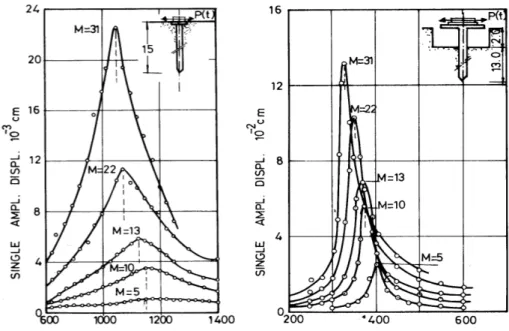
equilibrium under initial cyclic loading and (c) reloading after cyclic (Matlock et al., 1970) ... 37 Figure 3-2 P-y curves developed from static and cyclic lateral load tests on pile in stiff clay (Reese et al., 1975) ... 37 Figure 3-3 Field group test results indicating preferential load distribution to leading piles (Holloway et al., 1982) ... 41 Figure 3-4 Field pile group load test results depicting; a) cyclic degradation of resistance; b) distribution of load by row (Brown et al., 1987) ... 41 Figure 3-5 Dynamic pile response vs frequency (in rpm) from forced vibration tests: a) linear response; b) nonlinear response due to removal of supporting soil near pile head (Petrovski and Jurokovski, 1973) ... 44 Figure 3-6 Field pile forced vibration test set up (Scott et al., 1982)... 44
Figure 3-7 Field pile forced vibration test and earthquake observation: a) test set up and seismometer arrangement; b) forced vibration tests results illustrating influence of lateral support condition; c) structure to free field transfer function for three backfill cases; d)
observed and computed response spectra for seismic event (Kobori et al., 1991) ... 47
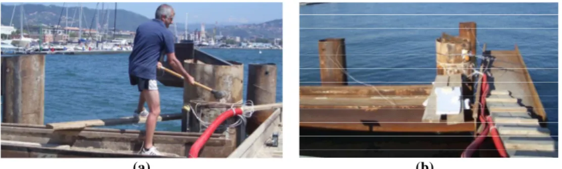
Figure 3-8 Impact load tests (a) and free vibration tests (b) performed by Dezi et al (2012, 2013, 2016) on three near-shore steel pipe piles vibro-driven into soft marine clay ... 49
Figure 3-9 Four installed micropiles (a) and lateral load test setup (b) in the experimental campaign carried out by Abd Elaziz and El Naggar (2014)... 51
Figure 4-1 Excerpt of the geological map of Osimo (from ISPRA, sheet 293, or. 1:10000)56 Figure 4-2 (a) Stratigraphic model, (b) Vs profile... 56
Figure 4-3 Directional velocity spectra and HVSR diagram of the investigated field ... 57
Figure 4-4 qc and fs profile with reference to the portion of soil interested by micropiles.. 57
Figure 4-5 Tube a manchèttes ... 59
Figure 4-6 Plan view of the testing field... 59
Figure 4-7 Insertion of an instrumented micropile into a grouted borehole ... 60
Figure 4-8 Packer for high pressure injections... 61
Figure 4-9 Execution of high pressure injections... 61
Figure 4-10 View of micropiles after high pressure injections ... 62
Figure 4-11 Single vertical micropiles ... 63
Figure 4-12 Inclined micropiles group... 64
Figure 4-13 Strain gages disposition on instrumented inclined and vertical micropiles .... 66
Figure 4-14 a) Adopted strain gages; b) Half bridge configuration. ... 67
Figure 4-15 Subsequent steps of installation of strain gauges ... 68
Figure 4-16 Displacement transducers with mechanical supports... 70
Figure 4-17 Instrumented hammer ... 71
Figure 4-18 a) Hydraulic jack; b) power pack with pressure transducer ... 72
Figure 4-19 Electro-mechanic vibrodyne... 72
Figure 4-20 Performance of adopter vibrodyne, equipped with light masses ... 73
Figure 4-21 (a) Signal conditioner HBM MGC plus; (b) DAQ device NI 9234... 75
Figure 4-22 Spider8 of HBM... 75
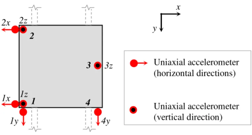
Figure 4-23 (a) Disposition of accelerometers on P1/P2 for ambient vibration tests; (b) view from the top, during an acquisition. ... 76
Figure 4-24 Disposition of accelerometers on the group cap for ambient vibration tests .. 77
Figure 4-25 Example of impact load on micropiles group: a) Time History; ... 78
Figure 4-26 (a) Typical configuration of horizontal impact load test on single micropiles; (b) during a test in the original configuration, and (c) with the pipe extension. ... 79
Figure 4-27 Disposition of accelerometers on the group cap for impact load tests... 80
Figure 4-28 Impact configuration on the group cap for impact load tests... 80
Figure 4-29 Configuration for 2-way cyclic loading on pile P1 and P2 ... 82
Figure 4-30 Arrangement for 2-way cyclic loading on P2... 83
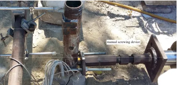
Figure 4-31 Details of the coupling between screwing device and reaction pile during test on P1... 83
Figure 4-32 Arrangement for 2-way cyclic loading on P1... 84
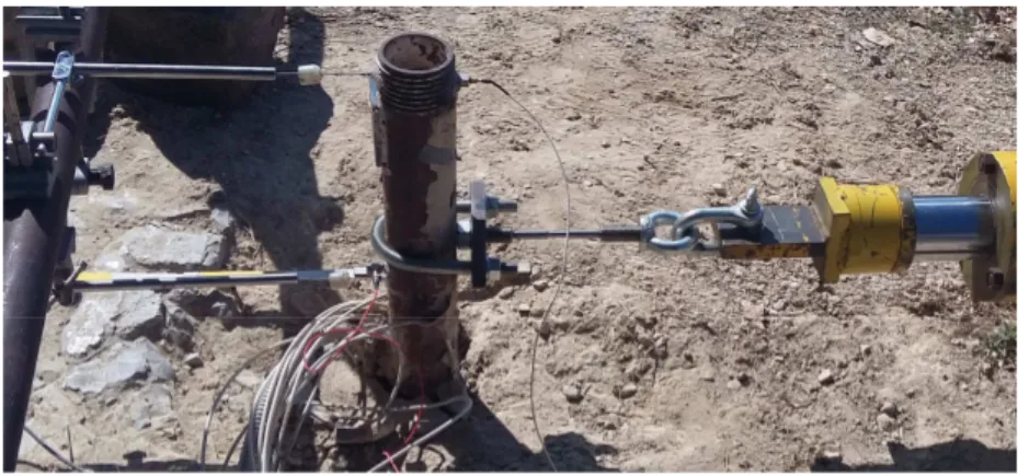
Figure 4-33 Details of the coupling between the load cell and pile P1... 84
Figure 4-34 Calibrated pins adopted for snap back tests, and corresponding tensile failure forced... 85
Figure 4-35 System adopted for the application of the release on P2... 86
Figure 4-36 Details: shackle/eyebolt system, calibrated pin, and pile head instrumentation. ... 86
Figure 4-37 Dynamic force-frequency curves in the vibrodyne configuration... 88
Figure 4-38 Forced vibration tests: (a) no added mass; (b) with added masses... 89
Figure 4-39 Acquired instruments (a), and (b) selection of acquired SGs according to different test configuration ... 89
Figure 5-1 Peak picking method of modal analysis: (a) FRF modulus plot; (b) Resonance detail; (c) Real part of a single mode plot; (d) Imaginary part of single mode plot... 93
Figure 5-2 Receptance (magnitude and phase plots) for undamped single degree of freedom system ... 94
Figure 5-3 Plots of real and imaginary parts of FRF for damped SDOF system... 95
Figure 5-4 Results of ambient vibration tests for (a) injected vertical micropiles, (b) simply grouted vertical micropile, (c) inclined injected micropile, along x and y direction in free head configuration... 98
Figure 5-5 Results of ILTs for single micropiles in free head configuration along dir x .. 100
Figure 5-6 Results of ILTs for (a) injected micropiles, and (b) simply grouted micropiles, along x and y direction in configuration B ... 101
Figure 5-7 Results of ILTs for P1 at difference depth (strain gage signals) ... 103
Figure 5-8 Results of ILTs for P2 at difference depth (strain gage signals... 103
Figure 5-9 First fundamental frequency evaluated from strain gauges signals for ... 104
Figure 5-10 Damping evaluated from strain gauges signals for P1 (a) and P2 (b)... 104
Figure 5-11 Time histories and Stockwell transform of 3 strain gage signals ... 105
Figure 5-12 Schematic interpretation of SGs signals during impact load tests ... 106
Figure 5-13 Normalized values close to the first resonance of (a) curvature (experimental and fitted values); (b) deformed shape for P1 and P2... 107
Figure 5-14 Experimental impedance functions of single vertical micropiles: real (a) and imaginary (b) parts of P1 and P2 ... 108
Figure 5-15 Derivation of simplified micropile head rotation ... 109
Figure 5-16 L1, pile head displacement for micropiles P1 and P2 for the monotonic load ... 110
Figure 5-17 L2, pile head displacement for micropiles P1 and P2 for the monotonic load ... 110
Figure 5-18 ϴ, approximated head rotation for P1 and P2 for the monotonic load... 110
Figure 5-19 Gap at the end of the first loading cycle on P1 ... 111
Figure 5-20 Strains profile at different loading levels ... 112
Figure 5-21 L2, pile head displacement for vertical micropiles over cycles... 114
Figure 5-22 L1 pile head displacement for vertical micropiles over cycles ... 114
Figure 5-23 Θ, micropile head rotation for vertical micropiles over cycles ... 114
Figure 5-24 Stiffness ratio vs. number of cycles and corresponding degradation parameter (slope of the fitting line in the log-log graph) at increasing displacement step: (a, b) step 1; (c, d) step 2; (e, f) step 3; (g, h) step 4; (i, l) step 5 ... 115
Figure 5-25 Trend of βs for different values of the ratio y/ymax, for P1 and P2 ... 116
Figure 5-26 Displacements (a) and acceleration (b) time histories registered during a free vibration tests (F4-T2) on micropile P2; (c) S-Transform of acceleration... 118
Figure 5-28 Profile of strains just before the release for the 4 force levels in (a) 1st series
and (b) 2nd series (pile P1)... 120
Figure 5-29 Profile of strains at the end of the free vibrations test for the 4 force levels in (a) 1st series and (b) 2nd series (pile P1) ... 121
Figure 5-30 Profile of strains just before the release for the 4 force levels in (a) 1st series and (b) 2nd series (pile P2)... 122
Figure 5-31 Profile of strains at the end of the free vibrations test for the 4 force levels in (a) 1st series and (b) 2nd series (pile P2) ... 123
Figure 5-32 Investigation via ambient vibration tests of the residual dynamic properties after free vibration tests on P1 (x and y axis)... 124
Figure 5-33 Investigation via ambient vibration tests of the residual dynamic properties after free vibration tests on P2 (x and y axis)... 124
Figure 5-34 Results of Ambient Vibration Tests on micropiles group... 125
Figure 5-35 Results of ILTs on micropiles group: (a) along x and (b) y direction ... 126
Figure 5-36 Mechanism for undertaking horizontal loading and moment of inertial origin, in vertical and inclined piles groups. Vectors indicate forces imposed by the cap on the piles while dashed lines correspond to the virtual location of the cap if the axial displacements of the piles are ignored. ... 128
Figure 5-37 Experimental impedance functions of micropiles group: real (a) and imaginary (b) parts along x and y directions... 129
Figure 5-38 Results of Stepped Sine tests along x axis for increasing value of K(α) ... 131
Figure 5-39 Results of Stepped Sine tests along y axis for increasing value of K(α) ... 131
Figure 5-40 Superficial soil cracks around the pile ... 132
Figure 5-41 Effect of repetition of the same stepped sine tests (K(α) = 23.4 N/Hz2, y axis) ... 132
Figure 5-42 Results of Stepped Sine tests along x axis for increasing value of in terms of horizontal and vertical accelerations ... 133
Figure 5-43 Results of Stepped Sine tests along y axis for increasing value of in terms of horizontal and vertical accelerations ... 133
Figure 5-44 Investigation via impact load tests of the residual dynamic properties after forced vibration tests on micropiles group along x (a) and y (b) direction ... 134
Figure 6-1(a) Pile group with inclined piles; (b) foundation subjected to interaction forces and (c) soil subjected to propagating seismic waves and interaction forces... 138
Figure 6-2 Displacements at point i due to forces applied at point j ... 143
Figure 6-3 Pile group model ... 146
Figure 6-4(a) Schematic representation of the analytical model used to reproduce impact tests and (b) main properties of soil and micropile ... 150
Figure 6-5 (a) Schematic representation of the analytical model used to reproduce impact tests on the inclined micropile group and (b) main properties of soil and micropiles ... 150
Figure 6-6 Configuration A: comparison between experimental and analytical results for a impact load in frequency domain (FRF of micropile head acceleration) and time domain (time history) on P1 (a, b) and P2 (c,d)... 151
Figure 6-7 Configuration B: comparison between experimental and analytical results for a impact load in frequency domain (FRF of micropile head acceleration) and time domain (time history) on P1 (a, b) and P2 (c,d)... 152
Figure 6-8 Configuration C: comparison between experimental and analytical deformation profiles at the first fundamental frequency, due to impact load test for P1 (a) and P2 (b)152 Figure 6-9 Comparison between experimental results of impact load tests on micropiles
group and analytical simulation along x (a) and y (b) directions ... 153
Figure 6-10 Experimental and theoretical impedance functions (real and imaginary parts) for the single vertical micropiles for P1 (a) and P2 (b)... 154
Figure 6-11 Experimental and theoretical impedance functions (real and imaginary parts) for the micropiles group along x (a) and y (b) directions... 154
Figure 6-12 Schematic view of the 3D FE linear model (a) and main geotechnical properties of soil and micropile (b) ... 155
Figure 6-13 Relationship between damping ratio and frequency (for Rayleigh damping) 157 Figure 6-14 Schematic view of the model calibrated on impact load tests, and of element used for pile, soil and quiet boundaries... 158
Figure 6-15 Infinite Element: a) positioning of the second node; b) examples of an acceptable and an unacceptable two-dimensional infinite element... 161
Figure 6-16 Schematic view of the 3D FE nonlinear model (a) and main geotechnical properties of soil and micropile (b) ... 164
Figure 6-17 Pile domain in non-linear model ... 164
Figure 6-18 Soil domain in non-linear model ... 165
Figure 6-19 Contact pressure-clearance relationship for “hard” contact ... 166
Figure 6-20 Comparison between experimental and simulated FRF of impact load test (a) and corresponding acceleration time history (b) for P1 in configuration A ... 167
Figure 6-21 Comparison between experimental and simulated FRF of impact load test (a) and corresponding acceleration time history (b) for P1 in configuration B ... 167
Figure 6-22 Comparison between experimental and simulated strain profile close to resonance at 25 Hz in terms of real component of FRF at increasing depth, for P1 ... 168
Figure 6-23 Subsequent steps of a simulated free vibration test (F1_P1 on micropile P2): (a) initial moments of the loading step; (b) advanced phase of the loading; (c) detail of the detachment between soil and micropile; (d) view from the top of the free vibrations after the release, with double side detachment. ... 170
Figure 6-24 Comparison between numerical and experimental result in terms of displacement registered at the pile head in the quasi static-loading phase ... 171
Figure 6-25 Comparison between numerical and experimental result in terms of acceleration registered at the pile head after the release... 171
List of Tables
Table 4-1 Synthetic scheme of the tests carried out... 54
Table 4-2 Geotechnical properties of superficial alluvial layer... 58
Table 4-3 Properties of materials and sections of micropiles ... 62
Table 4-4 Performance of adopted vibrodyne, equipped with light masses ... 74
Table 4-5 Stepped sine configuration carried out during forced vibration tests ... 88
Table 5-1 Fundamental frequencies of single micropiles determined via AVTs... 99
Table 5-2 Fundamental frequencies and damping of single micropiles ... 100
Table 5-3 Fundamental frequencies and damping of single micropiles ... 101
Table 5-4 Fundamental frequencies of P1 and P2 before and after snap back tests... 124
Table 5-5 Fundamental frequencies and damping of micropiles group via ILTs... 127
Table 5-6 Fundamental frequencies of micropiles group from stepped sine tests... 132
Abstract
Micropiles have been increasingly used in the last decades, both as new foundation system for buildings in seismic zone, and for the retrofit of existing structures damaged by earthquakes. Hence, it is essential to enhance the knowledge of the dynamic behaviour of micropiles under horizontal loading.
Dealing with traditional piles, the topic of soil-pile dynamic interaction is investigated by means of 3-D finite element models or theoretical approaches, whose results are extremely sensitive to many geometrical and mechanical parameters. Results of small and full scale tests are extremely precious to validate and calibrate both theoretical and numerical models. In particular, small-scale tests allow a higher flexibility in the application of dynamic forces, while full-scale in-situ tests have the advantage of accounting for the actual soil behaviour, and for the real boundary and interface conditions. Furthermore, their results represent a keystone for the calibration of numerical models and help in developing new simplified approaches able to represent the true behaviour of the soil-pile system. The available literature on dynamic in-situ tests on deep foundations is limited, and many unresolved questions still remain, such as the behaviour of piles and pile groups under large deformations, and the influence of execution stages and foundation configuration. The latter points are particularly crucial in the case of micropiles, which are often installed with a certain angle of inclination and completed with high pressure injections along the embedded shaft.
Despite their growing use, few results exist of static and cyclic lateral load tests on micropiles, and dynamic field tests data are almost absent; thus, an experimental campaign is carried out, that includes both two single vertical micropiles and a group of 4 inclined micropiles embedded in alluvial soils. One of the vertical micropiles is simply grouted, while the others have been also grouted with high pressure injections throughout valves a-manchèttes placed along the steel core of the shaft. The two vertical micropiles and one of the inclined micropiles are permanently instrumented with strain gages along the shaft; traditional execution steps are modified to allow the installation of strain gauges in laboratory, and the steps of sensors protection, transportation from lab to field, micropiles installation and execution of grouting and high pressure injections are carried out with special care in order to avoid as much as possible damage to strain gages.
Different testing techniques are adopted, to evaluate the dynamic behaviour of the single micropiles and of the micropile group under small to large deformations. In particular, ambient vibration tests, impact load tests and free vibration tests are performed on the vertical micropiles, while ambient vibration tests, impact load tests and forced vibration tests are performed on the group. Moreover, two-way cyclic horizontal load tests are performed on the single vertical micropiles to evaluate the evolution of micropile head horizontal stiffness with the number of cycles, and with the development of phenomena related to non-linearity (among all, the detachment at the interface between the micropile and the soil). Results are presented in terms of fundamental frequencies, damping and modal shapes obtained from accelerometers at the pile head and strain gages permanently
installed along micropiles shaft. Displacements of the micropiles head during cyclic load tests and free vibration tests are also shown. Finally, impedances functions are experimentally derived for both the single micropiles and the group.
The experimental data are then compared with numerical results obtained exploiting different models, properly calibrated: a 3-D approach for the dynamic interaction analysis of vertical and inclined micropile groups proposed by Dezi et al. (2009, 2016), is here adopted to simulate impact load tests on the single micropiles and on the group. Moreover, two 3-D finite element models are developed in a general-purpose Finite Element code, having different properties in terms of soil, pile and interface behaviour, to evaluate the response of micropiles in the linear and nonlinear range, under dynamic horizontal forces.
Keywords: Micropiles, Battered piles, Dynamic Soil-Foundation Interaction, Dynamic Identification Techniques, Soil-Pile Gap
Sommario
Negli ultimi decenni si è assistito ad un crescente utilizzo dei micropali, sia come fondazioni di nuove costruzioni in zona sismica, che per il retrofit di fondazioni danneggiate di edifici esistenti. È dunque essenziale rafforzare la conoscenza del loro comportamento dinamico sotto carichi orizzontali.
Per quanto riguarda i pali tradizionali, il tema dell’interazione dinamica palo-terreno è generalmente investigato per mezzo di modelli 3D agli elementi finiti o tramite approcci teorici, i cui risultati sono estremamente sensibili ai parametri geometrici e meccanici in gioco. I risultati di prove in piccola e grande scala sono dunque assai preziosi per validare e calibrare questi modelli teorici o numerici.
In particolare le prove su prototipi in piccola scala permettono una maggiore flessibilità nell’applicazione del carico dinamico, mentre le prove eseguite in-situ su pali in vera grandezza hanno il vantaggio di tenere in conto il reale comportamento del terreno, e delle effettive condizioni al contorno e all’interfaccia. I loro risultati, oltre ad essere fondamentali per la calibrazione di modelli numerici, possono rappresentare un punto di partenza per lo sviluppo di modelli semplificati che siano in grado di rappresentare il reale comportamento del sistema palo-terreno. Lo stato dell’arte su prove in sito eseguite su fondazioni profonde è limitato e permangono diverse questioni aperte, come il comportamento di pali singoli e in gruppo sotto grandi deformazioni, nonché l’influenza delle modalità esecutive e della configurazione. Gli ultimi due aspetti sono particolarmente importanti per i micropali, che vengono spesso installati con un certo angolo di inclinazione e completati con iniezioni ad alta pressione lungo il fusto.
Nonostante il loro crescente utilizzo, esistono pochi risultati specificatamente riguardanti prove di carico statico e ciclico su micropali, mentre prove di natura dinamica sono sostanzialmente assenti. Per colmare questa lacuna, è stata affrontata una campagna sperimentale che riguarda sia due micropali singoli verticali che un gruppo di quattro micropali inclinati realizzati in un deposito di natura alluvionale.
Uno dei micropali verticali è semplicemente trivellato, mentre gli altri sono stati completati con iniezioni ad alta pressione attraverso valvole di non ritorno posizionate lungo il fusto del micropalo. Entrambi i pali singoli verticali ed uno dei pali inclinati del gruppo sono permanentemente strumentati con estensimetri lungo il fusto; per permettere l’installazione dei sensori in officina, le tradizionali modalità esecutive sono state leggermente modificate e le fasi di protezione degli estensimetri, di trasporto dall’officina al sito, di installazione dei micropali, di getto e di esecuzione delle iniezioni ad alta pressione sono state realizzate con cura estrema per evitare il più possibile il danneggiamento dei sensori.
Nel corso della sperimentazione sono state utilizzate diverse tecniche sperimentali al fine di valutare il comportamento dinamico di micropali singoli ed in gruppo nel campo delle piccole, medie e grandi deformazioni. In particolare sui micropali singoli sono state eseguite prove di vibrazione ambientale, prove di impatto, prove in condizioni di vibrazioni libere. Sul gruppo sono state eseguite prove di vibrazione ambientale, prove di impatto e prove in condizioni di vibrazioni forzate. Inoltre sono state eseguite sui micropali singoli
prove di carico ciclico a doppia via, per valutare l’evoluzione della rigidezza orizzontale della testa del palo con il numero di cicli e con il conseguente sviluppo di fenomeni tipicamente non lineari (tra tutti, il distacco all’interfaccia tra micropalo e terreno circostante). I risultati delle prove dinamiche sono presentati in termini di frequenze fondamentali, smorzamento e forme modali ottenute dagli accelerometri sulla testa del palo e dagli estensimetri disposti lungo il fusto. Vengono mostrati anche gli spostamenti della testa dei micropali acquisiti durante le prove di carico ciclico e le prove in condizioni di vibrazioni libere. Infine, vengono proposte le funzioni di impedenza derivate sperimentalmente sia per i micropali verticali che per il gruppo.
I dati sperimentali sono confrontati con i risultati numerici ottenuti da diversi modelli opportunamente calibrati: dapprima l’approccio 3D per l’interazione dinamica cinematica ed inerziale di gruppi di pali verticali o inclinati proposto da Dezi et al. (2009, 2016) è stato utilizzato per simulare le prove di impatto sui micropali singoli verticali e sul gruppo di pali inclinati. Successivamente, con un codice commerciale agli Elementi Finiti, sono stati sviluppati e calibrati due modelli, caratterizzati da diverse caratteristiche in termini di proprietà del terreno, del micropalo e dell’interfaccia micropalo-terreno e che permettessero di stimare il comportamento dei micropali in campo lineare e non lineare sotto forze dinamiche orizzontali.
Keywords: Micropali, Pali Inclinati, Interazione Dinamica Terreno-Fondazione, Tecniche di Identificazione Dinamica, Gap Palo-Terreno
Chapter 1.
Introduction
1.1. Problems Statement
A micropile is a small-diameter (less than 300 mm), drilled and grouted replacement pile, typically reinforced. It is generally 7.5 or more meters in length and 300-1000 kN in load-carrying capacity. Micropiles undoubtedly offer many advantages (FHWA, 2005): firstly, their installation cause minimal disturbance to adjacent structures, soil, and environment, so they can be installed in access-restrictive spaces and in all soil types and ground conditions and where minimal disturbance to the existing structure is permissible; furthermore, since the installation procedure causes minimal vibration and noise and can be used in conditions of low headroom, micropiles are often used to underpin existing structures. Specialized drilling equipment is often required to install the micropiles from within existing basement facilities.
The use of micropiles to strengthen foundations of building dates back to the post war era and the reconstruction of cities in Italy. Since their conception in the 1950’s by dr. Fernando Lizzi (Lizzi, 1991), they have been increasingly used for several purposes: generally, they are used as for underpinning of existing foundations, however, recently, they have been frequently adopted for many other applications such as foundation support, soil settlement problems, bearing capacity problems, slope stabilization and deep excavations (Mascardi, 1982; Laefer, 1999; Bruce et al., 1997). Moreover, they have also been exploited for the seismic retrofitting and protection method to new and old structures which have suffered seismic damage (see Pearlman et al., 1993; Taylor et al., 1998; Zelenko et al., 1998; Misra et al., 1999; Juran et al, 2001; Shahrour and Juran, 2004). In the last decades, micropile technology has been evolving significantly, and nowadays it is considered a very attractive solution for the structural and seismic retrofitting of bridges, churches and other ancient cultural heritage and modern structures in many seismic areas. In Italy, mainly two technologies are adopted for micropiles. The original palo Radice or root pile is a small diameter, cast in place reinforced drilled pile, commonly designed to achieve a capacity in the range of 100-200kN. Casing fitted with a tungsten bit is drilled into the ground to the full depth of the pile. The drilling fluid (either water or bentonite mud) is injected inside the casing and flows in the annular space between the casing and the soil carrying away soil cuttings. After drilling and placing the reinforcement (a single bar or a small cage) sand cement mortar is pumped by means of a tramie pipe from the bottom of the hole, displacing away the drilling fluid. During the withdrawal of the casing, a pressure is applied to the grout, which is typically in the range of 0.3 to 1 MPa (it is limited by the capacity of the soil to maintain a grout-tight seal around the casing during its withdrawal).
Another micropile technology is presently available, sometimes referred to as Tubfix. In this case a steel tube with no return valves (tube a manchèttes), is positioned in the hole and the annular space between the tube and the hole wall is filled from the bottom with neat cement grout. A similar grout is injected at a pressure of 2 to 8 MPa using a double packer inside the tube a manchèttes, so that specific horizons can be treated, if necessary, several times. For this reason, Tubfix micropiles are also known as IRS (Injection Répétitive et Sélective), while Radice can be classified as IGU (Injection Globale et Unitaire). At the end of the injection stage, the steel tube is filled with grout. The load is mainly resisted by the steel tube. Capacity in the range of many hundreds to over 1000 kN may be achieved for Tubfix technology.
Since micropiles are designed not only to bear the ultimate load but even to limit the displacement of a structure, especially when they are used for retrofitting and rehabilitation of existing foundations, it is fundamental for micropile design to predict the complete load-displacement behaviour. The current design practice for micropiles is in fact based upon either the methods developed for large diameter drilled shafts and ground anchors or simplistic interpretation of micropile load tests similar to the approach used for analyzing tieback anchors. However, construction methods, structural characteristics of micropiles as well as soil-micropile interaction phenomena can be significantly different, so that the methods and parameters adopted for drilled shafts and ground anchors are not directly applicable. Hence, some authors performed numerical studies on micropiles under static, cyclic and dynamic lateral loading. On the other hand there are only a limited number of small/full scale experiments on micropiles. A review of those numerical and experimental researches is provided in Chapters 2 and 3, respectively.
A crucial aspect to be considered is that many different configurations can be adopted for micropiles implementation (Figure 1-1): micropiles can be connected vertically, but even in inclined forms around and below the foundations. In fact, by using the same type of equipment used for ground anchor and grouting projects, micropiles can be installed at any angle below the horizontal (battered micropiles). Besides, by adopting a network configuration, micropiles start to behave like tree roots, increasing the overall resistance. Inclined piles are able to resist higher lateral loading by exploiting their axial behaviour but, from the observations of past case histories, the behaviour of inclined large-diameter piles turns out to be ambiguous.
During 1989 Loma Prieta earthquake (Mw = 6.9) several port wharfs in which raked piles
were used suffered important damages: the Public Container Wharf at the 7th street
Terminal in the Port of Oakland was made with square concrete battered piles, and when the fill behind the wharf liquefied the poor tension connection to the deck failed (Figure 1-2a); on the other hand almost all the vertical piles remained undamaged. A similar type of failure was observed in the battered piles supporting the concrete wharf at the nearby Matson terminal, with additional damage to the back row of vertical piles. At the Oakland Outer Harbor Pier 7, the prestressed concrete batter piles failed near or at the connection to the pile cap.
In San Francisco, the Ferry Plaza pier experienced tensile failure at the connection of the deck to the prestressed concrete batter piles, with some of the piles punching the slab. Such failures, in any case, were most probably due to inadequate reinforcement in the top of the piles and to improper connection of piles to their caps (Figure 1-2b).
The Costa Rica earthquake (Mw = 7.5) caused severe damages over a wide area, including liquefaction-related collapse of several pile-supported bridges. For instance, the front batter piles of the Rio Banano bridge suffered flexural and shear damage whereas the vertical piles at the rear showed less damage (Figure 1-3a). An analogous type of damage was observed in the inclined piles supporting the abutments of the Rio Viscaya Bridge leading to large rotation and collapse of the deck. Again, the mode of failure of the batter piles suggests that damage resulted form the insufficient design of the pile-to-cap connection (Figure 1-3b).
In 1994 the Northridge earthquake (Ms = 6.8) produced a ground surface acceleration causing severe damage to the APL terminal in POLA Battered piles suffered from pull out and chipping of concrete at the pile caps.
The main reasons mentioned to be real or perceived drawbacks are summarized by Giannakou et al. (2010): the appearance of parasitic bending stresses on the piles due to soil settlement after the earthquake or to soil consolidation; the presence of large cyclic forces at the pile cap; the reduction in bending moment capacity due to seismically induced high tensile force; undesirable permanent rotation of the cap when the inclination of the piles is not symmetric; the increased structural shear with respect to buildings on vertical piles, due to the higher stiffness of the system.
In truth, in the very last years, many studies on the seismic response of batter piles and micropiles (Sadek and Shahrour, 2004 and 2006; Gerolymos et al., 2008; Padron et al., 2009; Carbonari et al., 2017) have shown that the response of well designed batter piles not only have a good performance for themselves, but that they can also be beneficial for the structure they support. Furthermore, case histories referring to Maya Wharf in the Kobe 1995 earthquake and the Landing Road Bridge in the Edgecumbe, New Zealand 1987 earthquake have highlighted the successful performance of battered piles.
Focusing specifically on micropiles, Bruce et al. (2005) show that “inclined piles should not be used for transmitting lateral loads to the soil, but if such piles are used, they must be safely designed to carry axial and bending loads.”, while Sadek and Isam (2004), by means of numerical analyses, proved that “inclination of micropile improves micropiles performance with respect to seismic loading. The inclination allows a better mobilization of the axial stiffness of micropiles and consequently leads to a decrease in both shearing forces and bending moment induced by seismic loading”. It is worth remembering that inclined micropiles, if well designed, give very attractive results in reducing liquefaction, while vertical do not (Bruce et al, 2005).
Nonetheless, the use of inclined piles is still not recommended by modern European codes. For instance, French Seismic Code AFPS 1990 states definitely that “inclined piles should not be used to resist seismic loads”, while the seismic Eurocode EC8/part 5 states that “It is recommended that no inclined piles be used for transmitting lateral loads to the soil. If, in any case, such piles are used, they must be designed to carry safely axial as well as bending loading”. Finally, the Italian code NTC 2008, reports the same limit for the use of inclined piles and add: “In those cases in which it is necessary to make use of inclined piles, they should be designed to withstand stresses derived from the analysis of soil-foundation system in seismic conditions”.
An important issue that should receive attention is that most of the studies concerning behaviour of micropiles (vertical or inclined) are essentially linear and thus adequate for the description of small displacements behaviour.
Micropile Micropiles group Micropiles network
Figure 1-1 Some micropiles configuration types (after Frank, 2006)
Figure 1-2 Damages of battered piles during the 1989 Loma Prieta earthquake: (a) at the port of Oakland; (b) at the port of San Francisco (after SEAOC, 1991)
Figure 1-3 (a) Preferential damage to front batter piles of Rio Banano bridge; (b) failure of Rio Viscaya Bridge Piles, during the 1991 Costa Rica earthquake (after
At larger displacements, micropiles and micropiles group are supposed to behave in a non linear fashion (changing dramatically their dynamic stiffness and damping) because of soil non-linearity at high strain, pile separation (gapping), slippage and friction.
Hence, to strengthen the knowledge of the seismic behaviour of vertical and batter micropiles in a wide strains range and to correct misconception often provoked by bad design of such foundation systems, analytical and numerical models, based on experimental data, should be developed and validated.
1.2. Thesis Objectives
This thesis is the result of an experimental investigation carried out on vertical and inclined micropiles. The experimental study proceeded from several needs:
o As already stated, there is a modest number of full scale tests performed directly on micropiles under horizontal loadings, and most of them consider static or cyclic load, while dynamic field tests data are substantially absent. Hence, the first aim of this study is that of point out the influence, on the horizontal dynamic behaviour of micropiles, of the execution techniques and configuration (i.e. high pressure injections, micropiles inclination, and restraint condition at the micropile head). o Experimental data represent a precious instrument to verify whether numerical and
analytical model specifically developed for traditional piles are able to account for the dynamic behaviour of micropiles; in addition they are fundamental to develop new simplified methods.
o The experimental program wants to investigate the system behaviour under different loading conditions (cyclic and dynamic, in the small, medium and very large strains range), in order to point out the characteristics of non linear phenomena interesting the soil-micropile system and the features of cyclic degradation.
o By comparing their dynamic behaviour with that of vertical piles, the research tries to put some light on the dynamic response of inclined piles; results are then compared with those obtained from an existing analytical model developed for inclined piles group.
o Finally, the experimental work hereinafter described comprises several techniques for the dynamic identification of systems, recently adopted in some areas of mechanical and civil engineering. To the author knowledge some of them have never been applied for the investigation of Soil Structure interaction problems, and the results are encouraging.
1.3. Organization of the thesis
In the present chapter, an introduction to the developed themes and the explanation of the objectives of the thesis are provided.
In Chapter 2 the current state of art on Soil Structure interaction is reported, including past numerical and analytical studies on piles and micropiles.
In Chapter 3 a review of the previous experimental campaigns performed on the dynamic behaviour of foundation on piles and pile groups under horizontal loading is presented with
special focus on full-scale field tests. A specific session is dedicated to small and full scale tests on micropiles.
Chapter 4 discusses the experimental program: firstly, the site characterization, based on laboratory and in-situ tests, is reported; then, the instrumentation of piles, carried out with particular care to prevent any damage related to micropile installation and high pressure injection is described. Finally, the different procedures carried out during the two campaigns (ambient vibration, impact load, free vibration, forced vibration and 2-way cyclic load tests) are described.
In Chapter 5 results are reported, with considerations regarding the influence of execution techniques, micropiles inclination, and the development of phenomena related to non linearity in the medium to high strain level tests.
Chapter 6 presents the simulation of the micropile-soil system behaviour by means of different approaches. First of all, an analytical model for the analysis of kinematic and inertial interaction for vertical and inclined piles groups in layered deposits is adopted. Then a 3-D Finite Element model is developed with a commercial general purpose code, and different modelling techniques are employed to investigate the behaviour of micropile-soil system in the linear and non linear field. Comparisons between numerical and experimental results are discussed.
Chapter 2.
Soil Structure Interaction
2.1. Introduction
The aim of a Soil Structure Interaction (SSI) analysis is to investigate the dynamic response of a structure interacting with the soil, and subjected to a time varying-load or to a dynamic excitation introduced through the soil (due, for example, to seismic waves). The dynamic behaviour of the structure cannot be studied independently of the wave propagation into the soil since, when the wave reaches the structure, part of it is scattered away, part of it is stored in the structure, and then it is re-injected in the soil or dissipated. The relevance of the study of SSI effects is straightforward for many fields of interest. For instance, when the dynamic motion is of seismic nature, the interaction between the structure and the soil foundation produces a modification (in terms of amplitude, frequency content and duration) of the seismic input at the base of the structure with respect to the free field motion (i.e. the motion far from any building). This modification produces the lengthening of the fundamental period of the structure and an increase of overall damping so that neglecting SSI effects is often assumed to be conservative; unfortunately, local seismic effects in conjunction with SSI may be detrimental for the seismic performance of certain structures (because of resonance effects, for instance), so that the perception of conservative design assumption is not always truthful (Mylonakys and Gazetas 2000); some of the modern seismic codes (Eurocode EC8, Italian NTC 2008) have recognized that under certain conditions SSI may significantly affect the seismic response of structure and suggest accounting for the flexibility of the soil foundation system in the superstructure design. The determination of SSI effects is also considered extremely important within the energy field and particularly for the offshore wind market. The actual trend is in fact to develop wind farms with higher capacity generators and in deeper waters, challenging the current offshore design procedures and involving the choice of adequate support structures for offshore wind turbines. In the design of offshore wind support structures fatigue derived from combined wind and wave loading is one of the critical issues. The potential of structural resonance with dynamic forces due to wind loading would result in large amplitude stresses and subsequent accelerated fatigue. For this reason, in practice, the wind turbine support structure is designed by setting the tower fundamental resonance between the blade passing and the rotor frequency. In addition, the overall damping of the structure has an important impact on the fatigue damage, since the amplitude of vibrations at resonance is inversely proportional to the damping ratios (Devriendt et al., 2012).
Effects of SSI have been extensively studied by many researchers. A general introduction can be found in Wolf (Wolf, 1985), where the soil is considered linear or linear equivalent and the SSI problem is treated in the frequency domain. This approach is often adopted since it allows a resolution in terms of superposition of simpler problems, but for strong motion excitation soil exhibit strongly inelastic behaviour, which is hardly estimated with a linear viscoelastic approximation. The full consideration of the non-linear character of the soil has to be performed in the time domain, as described by Wolf (1988). Concerning seismic problems, Kausel (1974) pointed out the necessity to consider not only the deformations of the soil due to the inertia forces in the structure (axial forces, base shear and overturning moment), but also the effect of a rigid foundation on a train of travelling seismic waves, that filters out high frequency components of the translational motions and generates rotational motions (in general rocking and torsion). Whitman introduced the terms inertial and kinematic interaction to distinguish these two types of effects. Later researchers confirmed the potential importance of kinematic interaction effects, especially for embedded foundations. Furthermore, Prof. J.P. Wolf (1985, 1994, and 2004) exhaustively dealt with the problem of dynamic SSI, identifying the main features of SSI in the increase of flexibility and effective damping (both due to energy radiation and material hysteresis) of the global system, in variation between foundation input motions and free-field ground motions and, finally, foundations deformations.
Methods that can be used to evaluate the above effects can be divided into direct and substructures approaches. In the former, the soil, the foundation system, and the structure are included into the same global model and analysed together, while in a substructure approach the SSI problem is separated into distinct parts, then combined to formulate the complete solution.
2.1.1. Direct approach
The direct approach provides the complete solution and represents the best way to perform 3D non-linear analyses in time domain. The entire system can be modelled in the direct approach with Finite Element Methods (FEM), Boundary Elements method (BEM) or mixed BEM-FEM approaches. In FEM models the far field domain is also explicitly modelled by means of artificial boundary that must be introduced to model the infinite (Figure 2-1), and that should include specific formulation to approximate the boundary conditions, avoiding the reflections of the outwardly propagating waves. The radiation conditions must be formulated on the artificial boundary that further assumes the role of transmitting boundary. Among other formulation of transmitting boundaries, the most known are the ones of Lysmer and Kuhlemeyer (1969), and Kausel (1988). The direct method can be performed also by separating the phase of estimation of the free-field motion (ground response analysis) from the phase of analysis of the whole structure-pile-soil system (i.e. when Beam on Linear on Non Linear Winkler Foundation method is used for the analysis).
2.1.2. Substructure approach
In the substructure method, the artificial boundary can be chosen to coincide with the structure soil-interface as shown in Figure 2-1b so that the two substructures, a bounded domain (consisting of the structure) and an unbounded domain (the soil extending to
infinity), can be modelled independently. The bounded domain can be modelled by means of the Finite Element method, with the possibility of including non-linear relation; on the other hand, the unbounded domain must be regular (i.e. a layered half space) and linear. Under such conditions analytical solutions that satisfy exactly the radiation condition formulated at infinity may be calculated. With these fundamental solutions (Green’s functions) a boundary-integral equation can be formulated, called the boundary-element method in discretized form, to calculate the interaction force-displacement relationship in the nodes located on the structure-soil interface. This dynamic stiffness, global in space and time, represents the rigorous boundary condition able to model the unbounded soil. The force-displacement relationships of the soil together with the discretized equations of motion of the structure represent the final system of equations of the total dynamic system. The substructure method thus permits each substructure to be analysed by the best suited computational technique.
According to the substructure approach, two distinct analyses have to be performed: the kinematic interaction analysis (performed in the soil-foundation sub domain) and inertial interaction analysis (in the structural sub-domain). Under the condition of linear behaviour, analyses are performed in the frequency domain, since properties of the soil are frequency dependent. As a result, the generalized motion experienced by the structure, traditionally known as Foundation Input Motion (FIM), as well as the dynamic impedance function (i.e. the complex valued force-displacement relationship at the interface) are determined. Then Inertial interaction analysis of the structure on compliant base (due to impedance functions) and subjected to FIM at the base, can be performed. Combination of these two responses provides the response of the system.
(a)
(b)
Figure 2-1 Dynamic system: a) direct method of analysis with finite-element mesh of soil and artificial boundary and b) substructure unbounded soil with global dynamic stiffness in
2.2. Review of models for Soil Pile Structure Interaction
A review of analytical methods for the evaluation of soil-pile-structure interaction under lateral loads is presented in the following section. As described by Poulos and Davis (1980) and Fleming et al. (1992), there are three major approaches for the load-deflection prediction of laterally loaded piles; these will be discussed hereinafter.2.2.1. Beam on Elastic Foundation Method
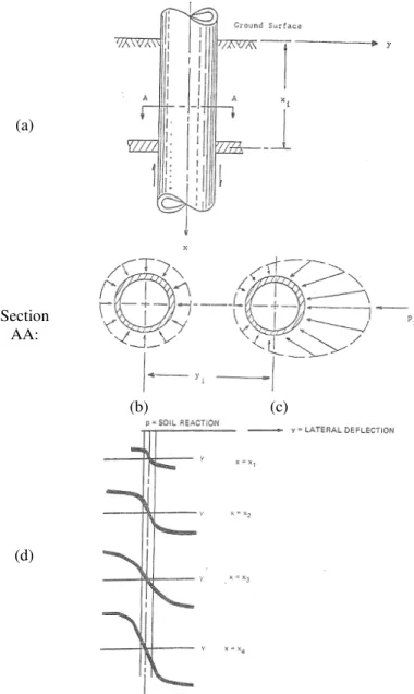
By accepting Winkler’s foundation assumption that each layer of soil responds independently to adjacent layers, a beam and a discrete springs system may be adopted to model a pile under lateral loading. Despite the fact that this assumption ignores the shear transfer between layers of soil, it is a popular and effective method for static and dynamic lateral pile response analyses. It consists in discretizing the soil-pile contact into a number of points where combinations of springs and dashpots represent the soil-pile stiffness and damping at each particular layer. These soil-pile springs may be linear elastic or non-linear; p-y curves typically used to model non-linear soil-pile stiffness have been empirically derived from field tests (Figure 2-2). In advanced applications, capabilities for soil-pile gapping, cyclic degradation, and rate dependency are also provided. A singular disadvantage of a beam-on-Winkler-foundation model is the two-dimensional simplification of the soil-pile contact, which ignores the radial and three-dimensional components of interaction. Exploiting the Baranov assumption, likely the extension of the well-known Winkler model to dynamic loading, transient excitations may be also analysed. Actually, for dynamic loadings, “free-field” soil acceleration time histories are usually computed in a separate site response analysis, double integrated to obtain displacement time histories, and then externally applied to the soil-pile springs.
Dezi et al. (2010) proposed a static equivalent approach to estimate the maximum kinematic interaction effects on piles subjected to lateral seismic excitation. Closed-form expressions are reported for the evaluation of the maximum free-field soil movements and for the computation of maximum pile shear force and bending moments. Firstly, modal analysis, combined with a suitable damped response spectrum, is used to evaluate the maximum free-field response. Secondly, the pile is schematised as a Winkler’s beam subjected to equivalent static forces defined according to soil vibration modal shapes and amplitude. The method may be applied by using response spectra suggested by National Standards or those obtained with accelerograms. The procedure proposed may be conveniently implemented in simple spreadsheets or in commercial finite element programs and easily used by practicing engineers. Method accuracy is demonstrated by comparing the results with those obtained with a more rigorous model. Good results may be achieved by considering only the first soil vibration mode making the procedure straightforward for practical design purposes. Among other models dealing with non-linear Winkler models (BNWF), the approaches of Nogami (1992) and Allotey and El Naggar (2008) are here recalled.
Nogami and coworkers developed a time-domain analysis focusing on a nonlinear zone around each pile under dynamic loading using p-y curves.
This was done using a pre-estimation factor to account for plastic deformations and opening of a gap at the pile-soil border. They also accounted for the group effect and the wave propagation away from the pile by introducing a far field element of three units in series, where each one has a spring and dashpot.
(a)
Section AA:
(b) (c)
(d)
Figure 2-2 Graphical definition of p and y: (a) elevation of section of pile; (b) earth pressure distribution prior and (c) after to lateral loading; typical family of p-y curves with depth
The near-field element accounts for the nonlinear soil behaviour in the vicinity of the pile shaft and the far-field element reproduces the elastic behaviour of the soil outside the region of strong nonlinear behaviour. Figure 2-3 shows a schematic view of the soil model proposed for the nonlinear sub-grade behaviour with near-field and far field element model. Years later, Allotey and El Naggar (2008) developed a versatile dynamic BNWF model for the analysis of shallow and deep foundations. It is based on a degrading polygonal hysteretic model encompassing multilinear backbone curve with defined rules for loading, reloading and unloading. It accounts for cyclic soil degradation through simulating unloading-reloading behaviour, it can simulate gap formation and closing along the soil-pile interface for cohesive soils and reloading in the slack zone (by means of a strain-hardening curve) for cohesionless soils. In addition to cyclic soil degradation/strain-hardening, the model can handle a reduced radiation damping due to increased soil non-linearity. The model is shown to be capable of representing various response features observed in SSI experiments. In addition, the predictions of the model for centrifuge tests of piles in weakening and partially weakening soil are shown to be in good agreement with the experimental results. The model has been developed as a stand-alone module then incorporated in commercial nonlinear structural analysis software SEISMOSTRUCT. Exploiting this module, Tombari et al (2013), evaluated the effect of soil non linearity and ground motion duration on the seismic response of bridge structures supported on extended pile shafts by performing Incremental Dynamic Analysis (IDA) in a two-step uncoupled procedure accounting for both site response and Soil-Pile-Structure interaction effects. In the 1st step, the free-field displacements within the soil deposit along the pile are defined by
means of a linear-equivalent site response analysis. In the 2nd step, a fully-coupled SPSI
analysis was performed using the BNWF model developed by Allotey and El Naggar. The relevance of non-linear effects is investigated by comparing results with those obtained with a linear-equivalent model for SPSI.
Dealing with inclined piles, Carbonari et al (2016) presented an analytical model, based on the beam-on-dynamic Winkler foundation approach, for the evaluation of impedances and kinematic response of single inclined piles. The pile is modelled as an Euler–Bernoulli beam having a generic inclination and the soil–pile interaction is captured by defining soil impedances according to expressions available in the literature for viscoelastic layers undergoing harmonic vibrations of a rigid disk. The coupled flexural and axial behaviour of the pile is governed by a system of partial differential equations, with the relevant boundary conditions, that is solved analytically in terms of exponential matrices. The solution for piles embedded in layered soils is achieved according to the direct stiffness approach by using the analytical solutions derived for generic pile sections embedded in homogeneous soils. Expressions of both the soil-foundation impedance functions and the foundation input motion are derived. Some applications, including comparisons of results with those obtained from rigorous boundary element formulations, are performed to evaluate the model capabilities. Classical stiffness and damping coefficients, based on the propagation of shear and pressure waves in plane-strain condition, are used in the applications to account for the soil–pile interaction; anyway, different formulations can be easily implemented.
2.2.2. Elastic Continuum Method
The representation of the soil as a homogeneous elastic continuum has also been proposed for the analysis of the soil-pile interaction. The elastic continuum analytical method is based on Mindlin’s (1936) closed form solution for the horizontal displacement caused by a horizontal point load within the interior of a semi-infinite elastic-isotropic homogeneous mass. The accuracy of these solutions is directly related to the evaluation of the Young’s modulus and the other elastic parameters of the soil. Since Mindlin’s solutions become singular when evaluating the displacement corresponding to the point where the load is located, integral solutions over a predefined area, representing a fraction of the pile surface, are used. These solutions are generally known as Green’s Functions, and define the displacement field due to an assumed loading system (pattern) associated with the pile-soil interaction. This approach is limited in the sense that non-linear soil-pile behaviour is difficult to incorporate (the equivalent linear method is available), and it is more appropriately applied for small strains, steady state vibration problems. In addition, layered soil profiles cannot be accommodated, and only solutions for constant, linearly increasing, and parabolically increasing soil modulus with depth have been derived. True continuum models do have the advantage of intrinsically modelling the effects of radiation damping, namely the loss of energy in the soil-pile system due to out-going stress waves that travel from pile-soil interface to infinity, whereas discrete models must artificially simulate this energy dissipation mode.
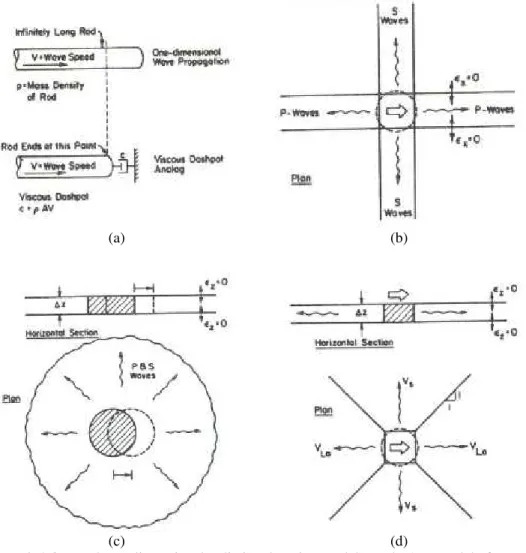
Among other authors working on the elastic continuum approach, Berger et al. (1977) proposed a simplified approach, assuming that the pile cross section (that moves horizontally) only generates one dimensional (1D) P-waves travelling in the direction of shaking, and 1D SH waves travelling perpendicular to the pile (Figure 2-4a, b).
In 1974, Novak published the first of many papers dealing with pile dynamics, where he adopted a plane strain, complex transmitting boundary adjacent to the pile for solution of pile stiffness and damping coefficients. Novak presented an approximate continuum approach to account for soil-pile interaction assuming the soil to be composed by a set of independent horizontal layers of infinitesimal thickness, which extend to infinity. As each plane is considered independent, this model may be viewed as a generalized Winkler model. The planes are homogeneous, isotropic, and linearly elastic, and are considered to be in a plane strain state (the plane strain condition is equivalent to incorporating the Winkler assumption into the continuum model). Using Baranov’s solution for the horizontal soil reaction to a rigid circular disc with harmonic horizontal displacement (representing a pile cross section), Novak formulated the differential equation of the damped pile in horizontal vibration (Figure 2-4c). He found the steady-state (particular) solution for harmonic motion induced through pile ends, and used this solution to find the dynamic stiffness of the pile head for different boundary conditions.
Gazetas and Dobry (1984) derived a method for substructuring the seismic soil-pile-structure problem into kinematic and inertial components from a parametric finite element study based on the work of Blaney et al. (1976). They proposed a simplified model for the evaluation of the radiation damping by assuming that compression-extension waves propagate in the two quarter planes along the direction of shaking, and that SH-waves propagate in the two quarters perpendicular to the direction of shaking (Figure 2-4d). For
the inertial interaction component, they described the pile head dynamic stiffness by a complex valued impedance function. The case of constant, linearly varying, and parabolically varying soil modulus were studied for single piles subjected to vertically propagating shear waves. The authors also considered the problem of dynamic pile response in layered soil profiles and described a method whereby static pile head stiffness was “corrected” to account for profiling, and the overall damping value was obtained from a weighted average of dashpot coefficients developed along the length of the pile. They also included a discussion of radiation damping models and proposed a simplified plane strain version. This model for radiation damping emanating from a laterally oscillating pile consisted of zones of waves travelling at the soil shear wave velocity Vs, and at Lysmer’s analogue velocity VLa. The authors made the important note that at frequencies less than the natural frequency (precisely the cut off frequency) of the system, there is no radiation damping. Gazetas (1991) made a complete survey of foundation vibration problems and included detailed design charts and equations for direct computation of pile head lateral and axial stiffness and damping coefficients in soil profiles characterized by constant, linearly varying, and parabolically varying soil modulus with depth.
(a) (b)
Figure 2-3 (a) Force displacement hysteresis loop and complex p-y curves; (b) Artificial hysteresis loop with a gap (Nogami et al., 1992)
(a) (b)
(c) (d)
Figure 2-4 One and two-dimensional radiation damping models: (a, b) 1-D Model of Berger et al (1977); (c) Plane-strain model of Novak et al. (1974); (d) Plane-strain model of