Safety Analyses with uncertainty
quantification for fusion and fission
nuclear power plants. Applications to
EU DEMO fusion reactor and BWRs.
Facoltà di Ingegneria Civile e Industriale
Dottorato di Ricerca in Energia e Ambiente - Scuola di Dottorato in Scienze e Tecnologie per l’Innovazione Industriale – XXXII Ciclo
Candidate
Matteo D’Onorio
ID Number: 1420584
Thesis Advisor
Prof. Gianfranco Caruso
Abstract
The EUropean DEMOnstrating fusion power reactor (DEMO) Water Cooled Lithium Lead (WCLL) breeding blanket concept is currently in its pre-conceptual design phase by the EUROfusion consortium members. It aims to be the first tokamak fusion reactor to demonstrate the capability for net electricity production, tritium-self-sufficiency, and a lifetime plasma operation of several full-power years. The WCLL breeding blanket is one of the two concepts being studied for implementation in the EU DEMO reactor. This concept relies on the separate-cooled architecture, where the liquid metal is utilized exclusively as tritium breeder and neutron multiplier, whereas the role of coolant is fulfilled by pressurized water.
Following the previous experience of the experimental International Thermonuclear Experimental Reactor (ITER), the design project of the DEMO reactor is constantly supported by safety studies for all the different breeding blanket concepts under investigation, so that best performance within safety requirements are achieved. The basic goal of safety is to ensure that a nuclear reactor will not contribute significantly to individual and societal health risks. These risks stem mainly from the radioactive inventory inside the reactor, so this basic goal translates into the prevention of radioactive material releases toward the environment. A secondary, but fundamental, objective is to prevent damage of fusion power plant main components. To deal with safety requirements within the DEMO project, a widely use of passive safety systems (a smart mix with active safety systems) will be made together with established safety principles, such as defense in depth and maintaining doses as low as reasonably achievable (ALARA).
The research activity described in this Ph.D. dissertation has the main objective to characterize and quantify the safety and environmental aspects of the EU DEMO WCLL concept design, studying the reactor response to some of the most severe possible accident scenarios. Safety analyses are performed with the fusion adapted versions of MELCOR code, to investigate the thermal hydraulic behavior of DEMO main components and radioactive source term mobilization. Moreover, the performed safety analyses, supported by sensitivity studies, could be useful to provide insight into physics and technology issues that need addressing to develop fusion as an optimal electricity generation alternative in the near future.
In this early development phase of the DEMO design, in the frame of the EUROfusion safety working project (WPSAE), a list of initiating events, which could start an accident sequence, has been identified through a Functional Failure Mode and Effect Analysis (FFMEA). Many accident sequences enveloping from these initiating events have been investigated comprehensively.
The dissertation is divided in three main parts. The first part concerns a general description of the principal safety issues associated with fusion reactors and provides an overview description of main EU DEMO components from a safety perspective. The second part contains preliminary safety studies relating to design basis accidents, beyond design basis situations and hydrogen mitigation systems. The progression of design basis accidents has
been simulated following a conservative approach taking into consideration the passive and active accident mitigation capabilities of the plant. Four different loss of coolant accident (LOCA) scenarios have been studied: in-vessel LOCA; ex-vessel LOCA; single in-vessel LOCA; and an in-box LOCA.
Concerning the multiple in-vessel LOCA, parametric analyses have been performed to determine the minimum flow area required by the suppression system pipework to limit the vacuum vessel (VV) pressure below the limit of 2 bar imposed as requirement by safety. Moreover, because limiters could be introduced in future design of the EU DEMO reactor to prevent the plasma to touch the breeding blankets plasma facing components (PFC), the same parametric study has been performed to evaluate their accident mitigation effects. In this framework, a new vacuum vessel suppression system (VVPSS) concept has been proposed following the ITER experience. It is based on six separated suppression tanks located in the containment basement, one of them is dedicated to retaining small leakages. The pipework consists mainly of six bleed lines connecting the VV to the small leakage tank, and five rupture disks line one for each suppression tank. To avoid steam and radioactive flows inside neutral beam ports, pipework connecting the vacuum vessel to the suppression system has been attached to the upper port. This last choice caused the necessity of a detailed nodalization of in-vessel volumes to model correctly steam flow path from VV to VVPSS and relative convective heat transfer effects between the modules’ back supporting structure (BSS) and the steam flowing at high velocity in the interspace volume between the BSS and the VV.
Relatively to a simple in-vessel event involving the rupture of 10 first wall cooling pipes, two different simulations have been performed to evaluate downstream isolation valves' effects in terms of radioactive releases and thermal hydraulic behavior of main DEMO components. In fact, the large number of downstream valves (isolation and Safety Relief Valves (SRV) to be installed, could give rise to safety and reliability constraints.
Concerning ex-vessel LOCA events, a very unlikely double-ended pipe rupture is postulated in a coolant distributor ring of the EU DEMO reactor. The fusion power termination system is assumed to terminate the plasma burn with a mitigated disruption. Two different simulations have been performed related to failure in FW-PHTS and BZ-PHTS, respectively. However, due to its similarity, only the results of the former are described. The objective of these analyses is to show that the accident consequences are within the safety requirements for tokamak building structures which must withstand large internal pressures as well as avoiding significant leak rate into the environment. Because the tokamak building layout of the EU DEMO is currently in a preliminary design phase, parametric studies have been performed to support design activities. A preliminary, but quite detailed, model of the TCR was made to take into account steam condensation phenomena on TCR walls, being the only available effect for mitigating the overpressure in the TCR. In fact, no active systems for containment cooling are currently foreseen for DEMO.
To complete the wide range of DBA performed for the EU DEMO WCLL concept, a preliminary analysis of an in-box LOCA has been carried out. This kind of accident has not
been yet deeply investigated for fusion reactors because of the lack of multi-phase safety-related system codes able to deal with water and liquid metals. To overcome this code limitation, a Python script has been developed for an external coupling of two MELCOR input decks working with different fluids. At each user-imposed time step the information of one MELCOR run are extracted and used as feedback for the other input deck.
In the framework of BDBA an ex-vessel LOCA and a Loss of Flow Accident (LOFA) have been studied with the objective to show the robustness of the defense in depth approach and demonstrating that no cliff edge effects occur in the safety analysis. In both the simulations the failure of active plasma shutdown system has been assumed as aggravating event. Differently from DBA these accident analyses should be performed using best estimate assumptions and not conservative ones. At this purpose, the failure temperature of FW structure is increased from 1273 K to 1598 K. However, this parameter results very correlated, in particular for the ex-vessel LOCA simulation, with the amount of tritiated water and other radioactive aerosols that could be released toward the external environment. Instead, preliminary safety analyses for the LOFA beyond event, highlighted that the major safety concern is not related to radiological releases, but to the huge pressurization of in-vessel components, for such a reason this accident has been simulated using a lower pressure setpoint for safety relief valves. Three different simulations have been performed, by changing the number of FW channels affected by the rupture.
In-box LOCAs, as well as other accidents involving a chemical reaction between hot steam and lead lithium, could led to the production of large amounts of hydrogen inside the tokamak vacuum chamber. In order to avoid that flammable concentrations could be achieved, the production of hydrogen must be limited and properly monitored. In particular, the simultaneous presence of hydrogen and dust in the VV volume enhances the risk of explosion. After a short description of possible technical solutions suitable for EU DEMO to mitigate hydrogen concentration, preliminary accident study involving the use of passive autocatalytic recombiners (PARs) are reported. The MELCOR ESF package has been activated to simulate the presence of PARs directly installed in the atmosphere of the VVPSS suppression tanks.
Successively, in the third part, sensitivity and uncertainty analyses are reported. Because severe accidents in both fission and fusion power plants involve a wide range of uncertain phenomena and parameters, sensitivity and uncertainty analysis have to be performed to evaluate the influence of input parameters on selected figures-of-merit (FoMs). At this purpose a Python interface has been developed to allow the interaction between RAVEN and MELCOR. The Python interface allows to perturb all the parameters accessible through the MELCOR input deck. In such a way RAVEN is capable to investigate the system response as well as the input space using sampling schemes. Two sensitivity and uncertainty analyses have been performed, with applications to EU DEMO reactor and to the unit 3 of the Fukushima Daiichi power plant.
Table of Contents
1 Introduction ... 20 Document outline ... 21 2 Thermonuclear fusion reactor technology ... 22 Tokamak reactors ... 22 3 Safety in fusion reactors ... 26Internal energies that can mobilize source terms ... 27
Radioactive mobilizable sources ... 28
3.2.1 Tritium ... 29
3.2.2 Dust and activated products ... 29
4 Overview of EU DEMO plant and systems ... 31
DEMO Vacuum Vessel ... 33
DEMO Cryostat ... 35
Divertor ... 36
WCLL Breeding Blankets ... 38
4.4.1 First wall ... 39
4.4.2 Breeding zone ... 39
4.4.3 Back Supporting Structure and attachments ... 40
Primary Heat Transfer System ... 41
4.5.1 Sector collectors ... 42
4.5.2 Ring ... 42
4.5.3 BZ Once Through Steam Generator ... 43
4.5.4 FW PHTS IHX ... 44
4.5.5 Pumps ... 45
4.5.6 Pressurizers design ... 45
Tokamak Building ... 45
Vacuum vessel pressure suppression system ... 47
5 EU DEMO MELCOR model ... 49
In-vessel and ex-vessel PHTS nodalization ... 50
Vacuum vessel and VVPSS nodalization ... 55
TCR nodalization ... 57
Divertor model ... 59
Source term modeling ... 59
6 Design basis accident analyses ... 61
Multiple First Wall/Blanket PHTS pipe break inside the vacuum vessel ... 62
6.1.1 Worst case scenario: Results and discussion ... 63
6.1.2 Baseline scenario results ... 69
6.1.3 Conclusions ... 74
6.2.1 Event Sequence ... 75
6.2.2 Results and discussion ... 75
6.2.3 Source term mobilization ... 80
6.2.4 Conclusions ... 82
Ex vessel LOCA ... 83
6.3.1 Ex-vessel LOCA from FW-PHTS ... 85
In-box LOCA: preliminary study and methodology ... 89
6.4.1 Accident description ... 90
6.4.2 Methodology and assumptions ... 90
6.4.3 MELCOR model ... 92
6.4.4 Conclusions ... 94
7 Beyond design basis accidents analyses ... 95
Ex-VESSEL LOCA without plasma shutdown ... 95
7.1.1 Event Sequence ... 95
7.1.2 Results and discussion ... 96
7.1.3 Radiological Releases ... 101
7.1.4 Conclusions ... 103
LOFA without plasma shutdown ... 104
7.2.1 Event Sequence ... 104
7.2.2 Results and discussion ... 105
7.2.3 Source term mobilization ... 109
7.2.4 Conclusions ... 111
8 Hydrogen explosion mitigation ... 113
Hydrogen production in fusion reactors ... 113
Hydrogen risk mitigation: technical solutions in fusion plants ... 116
MELCOR simulations for hydrogen mitigation ... 117
8.3.1 MELCOR hydrogen mitigation model ... 117
In-VV LOCA results ... 117
LOFA without plasma shutdown results ... 120
Conclusions ... 122
9 Uncertainty and sensitivity analysis with the RAVEN code ... 123
The RAVEN tool ... 123
Development of the RAVEN-MELCOR coupling ... 124
Sensitivity analysis for an ex-vessel LOCA without plasma shutdown ... 126
9.3.1 Accident description ... 126
9.3.2 Variables and sampling ... 126
9.3.3 Main outcomes from the sensitivity analysis ... 126
9.3.4 Conclusions ... 129
9.4.1 Introduction ... 130
9.4.2 MELCOR model ... 130
9.4.3 Accidental sequence models ... 136
9.4.4 Systems operation simulation ... 137
9.4.5 Accident Analysis Results ... 143
9.4.6 Variables and sampling ... 157
9.4.7 Results of sensitivity and uncertainty analysis ... 160
10 Conclusions and perspective ... 169
List of Tables
Table 3.1-1 – Energy sources in EU DEMO and ITER ... 27
Table 3.2-1 - EU DEMO basic tokamak parameters [33] ... 32
Table 3.2-2 - DEMO and WCLL BB power balance [32] ... 33
Table 4.4-1 - WCLL BB water cooling system integration and sizing [48] ... 41
Table 4.5-1 - Primary and secondary systems OTSG TH parameters [50] ... 43
Table 4.5-2 - BZ PHTS OTSG parameters [50] ... 44
Table 4.5-3 - WCLL BB and FW PHTS main data [50] ... 44
Table 4.5-4 - Water-molten salt HEX tube dimensions [50] ... 44
Table 4.5-5 - FW PHTS intermediate heat exchanger parameters [50] ... 45
Table 4.5-6 - PHTS MCP power [50] ... 45
Table 5.1-1 - Hydraulic parameters for feeding water pipes ... 51
Table 5.1-2 - Hydraulic parameters for water manifolds ... 52
Table 5.1-3 - Breeding modules nodalization and water inventory (1 sector) ... 53
Table 5.1-4 – Total in-VV water Inventory ... 53
Table 5.1-5 - Hydraulic parameters for ring distributors pipes ... 54
Table 5.1-6 - Hydraulic parameters for ring distributors pipes ... 54
Table 5.2-1 – VV flow phat ... 56
Table 5.3-1 – Containment flow path ... 58
Table 5.4-1 – Divertor model data ... 59
Table 6.1-1 – Possible transient sequence for a DBA with the failure of limiters function .... 63
Table 6.1-2 – Pressure peak inside the upper port for different cases ... 66
Table 6.1-3 – Pressure inside the upper port for different cases ... 71
Table 6.2-1 – Possible transient sequence for an in-vessel LOCA ... 75
Table 6.2-2 – Pressure Values ... 78
Table 6.2-3 – VVPSS components intervention time ... 78
Table 6.3-1 – Containment flow path ... 84
Table 6.3-2 - Possible transient sequence for an ex-vessel LOCA from FW-PHTS ... 85
Table 7.1-1 – Possible transient sequence for an ex-vessel LOCA without plasma shutdown 95
Table 7.1-2 – Pressure Values ... 100
Table 7.1-3 – VVPSS components intervention time ... 100
Table 7.1-4 – Mass of Hydrogen ... 101
Table 7.2-1 - SRVs and trip valves setpoint ... 104
Table 7.2-2 - Possible transient sequence for a LOFA without plasma shutdown ... 105
Table 7.2-3 – Mass discharged toward VV ... 107
Table 7.2-4 – Trip valves intervention time ... 107
Table 7.2-5 – Pressure inside the plasma chamber ... 107
Table 7.2-6 - VVPSS components intervention time ... 108
Table 7.2-7 – Mass of ACP [g] ... 111
Table 7.2-8 – Mass of tungsten dust [kg] ... 111
Table 7.2-9 –Mass of tritiated water [g] ... 111
Table 7.2-10 –Releases from DEMO first confinement barrier ... 111
Table 8.3-1 – Main input parameters for PAR modelling with MELCOR ... 117
Table 8.4-1 – Data related to PAR operation ... 119
Table 8.5-1 – Data related to PAR operation ... 122
Table 9.3-1 – Perturbed parameters ... 126
Table 9.3-2 - VV maximum pressure, descriptive statistic ... 127
Table 9.4-1 - Axial and radial peaking factor ... 131
Table 9.4-2 – Initial core inventory ... 136
Table 9.4-3 Accident Time history ... 137
Table 9.4-4 - RCIC and HPCI systems Design Specifications [98] ... 138
Table 9.4-5 - Relief and Safety mode opening pressure ... 139
Table 9.4-6 – AO time history [102] ... 141
Table 9.4-7 – Spray operations ... 141
Table 9.4-8 – Water injection history ... 142
Table 9.4-9 – Fukushima 3 selected uncertainty parameters ... 157
List of Figures
Figure 2.1.1 – Principle of magnetic confinement of a plasma in a tokamak [8] ... 23
Figure 2.1.2 – Tokamak reactor ... 24
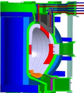
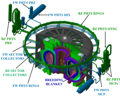
Figure 4.1.1 - Overview of the DEMO Tokamak Machine, Vacuum Vessel (in green) with
main components [34] ... 34
Figure 4.2.1 – General view of the final cryostat and bioshield design concept (DEMO 2017)
[36] ... 36
Figure 4.3.1 – 3D view of the DEMO Divertor [42] ... 37
Figure 4.4.1 - Layout of FW cooling channels [47] ... 39
Figure 4.4.2 - WCLL BZ DWT arrangement [48] ... 40
Figure 4.4.3 - WCLL2018.v0: detail of the BSS [48] ... 40
Figure 4.4.4 – EU DEMO sector piping system [32] ... 41
Figure 4.4.5 – Detail on OBC pipes connection. BSS removed for clarity [48] ... 41
Figure 4.5.1 - WCLL PHTS CAD model integrated with tokamak building ... 43
Figure 4.6.1 – EU DEMO tokamak building ... 46
Figure 4.6.2 – Tokamak building levels ... 46
Figure 4.6.3 – DEMO preliminary plant site layout [53] ... 47
Figure 4.7.1 –VVPSS connection to VV upper port ... 48
Figure 4.7.2 - VVPSS suppression tanks inside the tokamak building ... 48
Figure 4.7.3 - Tokamak building basement level with drain tank room available volume in red
... 48
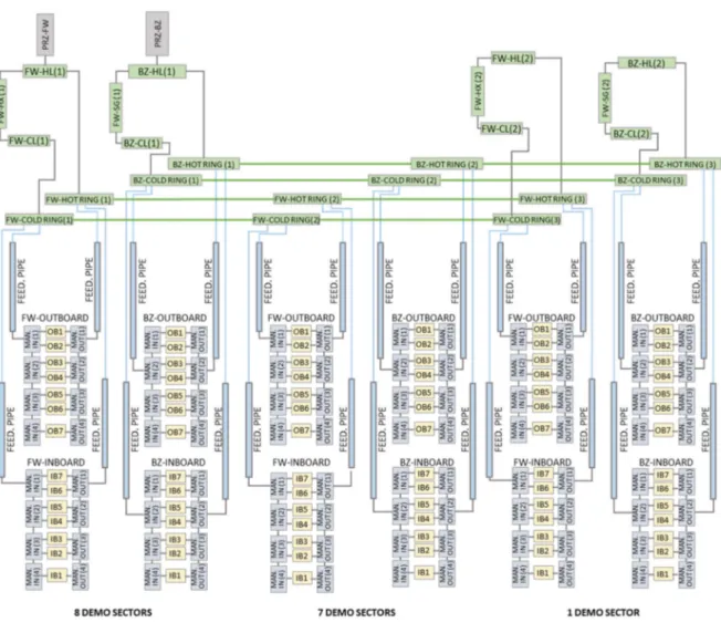
Figure 5.1.1 - Thermal hydraulic MELCOR nodalization scheme of the DEMO reactor ... 50
Figure 5.1.2 - BZ and FW cooling water manifolds [32] ... 51
Figure 5.1.3 – DEMO sector piping system [32] ... 51
Figure 5.1.4 - Thermal hydraulic nodalization scheme of one segment ... 52
Figure 5.1.5 - Thermal hydraulic nodalization scheme of the DEMO PHTS ... 54
Figure 5.1.6 – MELCOR HS-CVH coupling ... 55
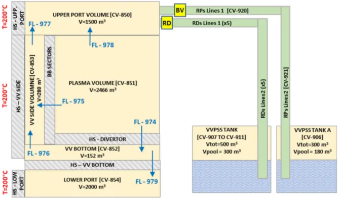
Figure 5.2.1 – VV and VVPSS nodalization scheme ... 56
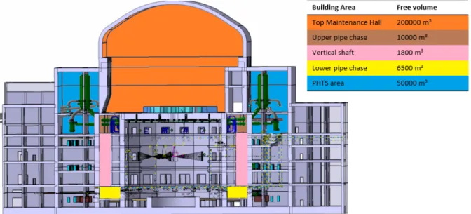
Figure 5.3.1 – Tokamak building compartment and free volumes available for steam
expansion ... 57
Figure 5.3.2 – Upper pipe chase volume (in red) ... 58
Figure 5.3.3 – Vertical shaft (in red) ... 58
Figure 5.3.4 - Lower pipe chase (in red) ... 58
Figure 5.3.5 – MELCOR tokamak containment building nodalization ... 59
Figure 6.1.1. DEMO poloidal cross-section with inboard-midplane, upper, outboard midplane,
and outboard lower limiters (in red) ... 63
Figure 6.1.2 - MFR into upper port and plasma volume (Case_RD_1.6) ... 64
Figure 6.1.3 – Total mass discharged inside the VV (Case_RD_1.6) ... 64
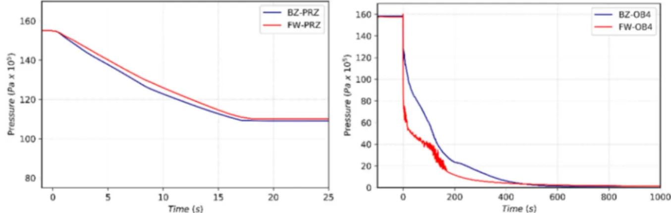
Figure 6.1.4 - Pressure in FW and BZ PHT pressurizer for a selected case (case RD_1.6) .... 65
Figure 6.1.5 - Pressure in FW and BZ OB4 volumes (case RD_1.6) ... 65
Figure 6.1.6 - Upper port pressure for different rupture disks flow area ... 65
Figure 6.1.7- Pressure in VV volumes and triggering setpoint of RDs and BVs
(Case_RD_1.6) ... 66
Figure 6.1.8- VV and VVPSS tank pressure (Case RD_1.6) ... 66
Figure 6.1.9- Mass of steam flowing toward the bleed lines tank (tank A) ... 67
Figure 6.1.10 - Mass of steam flowing toward one rupture disk lines (tank B) ... 67
Figure 6.1.11 – Mass entering the VV vs total mass of steam discharged in the VVPSS tanks
(Case RD_1.6) ... 67
Figure 6.1.13 - Mass of hydrogen in VVPSS volumes ... 68
Figure 6.1.14 – Mass of W dust in VVPSS for different RDs flow area ... 68
Figure 6.1.15 – Mass of ACP aerosol in VVPSS for different RDs flow area ... 68
Figure 6.1.16 – Mass of tritiated water in VVPSS for different RDs flow area ... 69
Figure 6.1.17 – VVPSS pressure (case RD_1.3) ... 70
Figure 6.1.18 - VVPPS atmosphere temperature (case RD_1.3) ... 70
Figure 6.1.19 – Mass flow rate toward the upper port (case RD_1.3) ... 71
Figure 6.1.20 - Mass of water flowing toward the upper port (RD_1.3) ... 71
Figure 6.1.21 - Upper port pressure for different rupture disks flow area ... 71
Figure 6.1.22 – Steam mass flow rate flowing toward the bleed lines tank (tank A) ... 72
Figure 6.1.23 -Mass of steam flowing toward the rupture disk lines (tank B) ... 72
Figure 6.1.24 -Pressure in VVPPS suppression tanks (Case RD_1.3) ... 72
Figure 6.1.25 -Temperature in VVPPS suppression tanks (Case RD_1.3) ... 72
Figure 6.1.26 -Total mass of hydrogen in VV and VVPSS volumes (Case RD_1.3) ... 73
Figure 6.1.27 -Total mass of hydrogen in VVPSS suppression tanks (Case RD_1.3) ... 73
Figure 6.1.28 – Mass of W dust in VVPSS for different RDs flow area ... 74
Figure 6.1.29 – Mass of ACP aerosol in VVPSS for different RDs flow area ... 74
Figure 6.1.30 – Mass of tritiated water in VVPSS for different RDs flow area ... 74
Figure 6.2.1 – Pressure transient in FW and BZ in-vessel volumes ... 76
Figure 6.2.2 - Pressure transient in FW and BZ pressurizers ... 76
Figure 6.2.3 - Temperature FW-OB4 module affected by PD ... 76
Figure 6.2.4 – Mass flow rate entering the VV ... 77
Figure 6.2.5 – Mass of water and steam entering the VV ... 77
Figure 6.2.6 – Pressure in VV volumes (Case 1) ... 77
Figure 6.2.7 – Pressure in VV volumes (Case 2) ... 77
Figure 6.2.8 – VV, VVPSS Tank A and Tank B pressure transient (Case 1) ... 78
Figure 6.2.9 – VV, VVPSS Tank A and Tank B pressure transient (Case 2) ... 78
Figure 6.2.10 – VVPSS tanks pressure transient (Case 1) ... 78
Figure 6.2.11 – VVPSS tanks pressure transient (Case 2) ... 78
Figure 6.2.12 - Tank A and Tank B pool temperature (Case 1) ... 79
Figure 6.2.13 – Tank A and Tank B pool temperature (Case 2) ... 79
Figure 6.2.14 - Mass of hydrogen in VV and VVPSS tanks (Case 1) ... 79
Figure 6.2.15 - Mass of hydrogen in VV and VVPSS tanks (Case 2) ... 79
Figure 6.2.16 - Temperature FW outboard volumes (Case 1) ... 80
Figure 6.2.17 - Temperature FW Inboard volumes (Case 1) ... 80
Figure 6.2.18 - Temperature FW outboard volumes (Case 2) ... 80
Figure 6.2.19 - Temperature FW inboard volumes (Case 2) ... 80
Figure 6.2.20 – Mass of W dust in VV and VVPSS volumes ... 81
Figure 6.2.21 – Mass of W dust deposited on VV surfaces ... 81
Figure 6.2.22 – Mass of ACP in PHTS, VV and VVPSS volumes ... 81
Figure 6.2.23 – Mass of ACP deposited on VV surfaces ... 81
Figure 6.2.24 – Mass of HTO in PHTS, VV and VVPSS volumes ... 82
Figure 6.3.1 – Pressure in the UPC after a LOCA from the FW-PHTS distributor ring ... 84
Figure 6.3.2 - Pressure in the UPC after a LOCA from the BZ-PHTS distributor ring ... 84
Figure 6.3.3 – Pressure transient in FW and BZ pressurizers ... 86
Figure 6.3.4 - Pressure transient in FW and BZ in-vessel volumes ... 86
Figure 6.3.5 – Pressure transient in TCR volumes ... 86
Figure 6.3.6 – Atmosphere temperature of TCR volumes ... 86
Figure 6.3.7 – Mass flow rate from ring distributor guillotine break ... 87
Figure 6.3.9 – Temperature peak on OB4 volume FW HS after a mitigated PD ... 87
Figure 6.3.10 – FW temperature of outboard volumes (poloidal distribution) ... 87
Figure 6.3.11 – ACP distribution in PHTS and TCR volumes ... 88
Figure 6.3.12 – HTO distribution in PHTS and TCR volumes ... 88
Figure 6.4.1 - DEMO Equatorial outboard module [66] ... 89
Figure 6.4.2 - Flow path of LiPb and rupture area considered for the analysis [66] ... 90
Figure 6.4.3 - Calculation methodology scheme ... 91
Figure 6.4.4 - Water circuit scheme ... 92
Figure 6.4.5 - Lithium lead circuit scheme ... 92
Figure 6.4.6 – Water mass flow rate from rupture ... 93
Figure 6.4.7 - Non-reacting water entering in the breeding module ... 93
Figure 6.4.8 – Hydrogen generation rate for different reaction coefficients ... 93
Figure 6.4.9 - Breeding module pressure for different reaction coefficients ... 93
Figure 6.4.10 - Breeding module temperature for different reaction coefficients ... 94
Figure 7.1.1 – Pressure transient in FW and BZ pressurizers ... 96
Figure 7.1.2 - Pressure transient in FW and BZ in-vessel volumes ... 96
Figure 7.1.3 – Mass flow rate from ring distributor guillotine break ... 97
Figure 7.1.4 – Mass of liquid water and steam discharged into the Upper Chase area ... 97
Figure 7.1.5 – TCR pressure ... 97
Figure 7.1.6 - Atmosphere temperature of TCR volumes (Cae 1) ... 97
Figure 7.1.7 - Atmosphere temperature of TCR volumes (Cae 2) ... 97
Figure 7.1.8 - OB1-FW temperature ... 98
Figure 7.1.9 – Mass flow rate entering VV ... 99
Figure 7.1.10 - Mass of steam and water entering the VV (Case 1) ... 99
Figure 7.1.11 - Mass of steam and water entering the VV (Case 2) ... 99
Figure 7.1.12 – Pressure in the plasma volume ... 99
Figure 7.1.13 – Pressure in TCR, VV, VVPSS volumes (Case 1) ... 100
Figure 7.1.14 – Pressure in TCR, VV, VVPSS volumes (Case 2) ... 100
Figure 7.1.15 – Mass of hydrogen in VV, VVPSS and TCR volumes (Case 1) ... 101
Figure 7.1.16 – Mass of hydrogen in VV, VVPSS and TCR volumes (Case 2) ... 101
Figure 7.1.17 – Mass of W dust in VV and VVPSS volumes ... 101
Figure 7.1.18 – Mass of W dust deposited on VV surfaces ... 101
Figure 7.1.19 – Mass of ACP VV and VVPSS volumes ... 102
Figure 7.1.20 – Mass of ACP in PHTS and TCR volumes ... 102
Figure 7.1.21 – Mass of HTO in VV and VVPSS volumes ... 102
Figure 7.1.22 – Mass of HTO in PHTS and TCR volumes ... 102
Figure 7.2.1 – FW pump shutdown transient ... 105
Figure 7.2.2 – Mass flow rate in OB1-FW module ... 105
Figure 7.2.3 – OB1-FW module temperature ... 106
Figure 7.2.4 - Mass flow rate toward VV ... 106
Figure 7.2.5 - Integral MFR toward VV ... 106
Figure 7.2.6 – Pressure inside the Plasma Chamber (CV851) ... 107
Figure 7.2.7 - Pressure in VV and VVPSS (tank B to F) ... 108
Figure 7.2.8 - Pressure in VVPSS (tank B to F) ... 108
Figure 7.2.9 – Mass of steam in VV ... 108
Figure 7.2.10 - Mass of Hydrogen produced by W-H2O reaction ... 109
Figure 7.2.11 - Temperature FW outboard modules ... 109
Figure 7.2.12 - Temperature FW inboard modules ... 109
Figure 7.2.13 - Mass of ACP in VV volumes(10 channels melt) ... 110
Figure 7.2.15 - Mass of tungsten dust in VV volumes (10 channels melt) ... 110
Figure 7.2.16 - Mass of tungsten dust in VVPSS tanks (10 channels melt) ... 110
Figure 7.2.17 - Mass of HTO in VV volumes (10 channels melt) ... 110
Figure 7.2.18 - Mass of HTO in VVPSS tanks (10 channels melt) ... 110
Figure 8.1.1 - Total amount of hydrogen in BZ [75] ... 115
Figure 8.4.1 – Mass of hydrogen in VV and VVPSS volume without PAR (§ 6.2) ... 118
Figure 8.4.2 – VVPSS volumes pressure transient ... 118
Figure 8.4.3 – VVPSS volumes temperature ... 118
Figure 8.4.4 – Mass of hydrogen in VVPSS ... 119
Figure 8.4.5 – Hydrogen mass fraction in VVPSS atmosphere ... 119
Figure 8.4.6 – Hydrogen removal rate ... 119
Figure 8.4.7 - Mass of H
2removed by PAR ... 119
Figure 8.5.1 – Mass of H
2produced because of W-steam interaction ... 120
Figure 8.5.2 – VVPSS temperature ... 120
Figure 8.5.3 - VVPSS pressure ... 120
Figure 8.5.4 – Mass of hydrogen in VVPSS ... 121
Figure 8.5.5 – Hydrogen removal rate ... 121
Figure 8.5.6 - Mass of H
2removed by PAR ... 121
Figure 8.5.7 – Hydrogen mole fraction inside VVPSS ... 122
Figure 9.2.1 - RAVEN-MELCOR coupling ... 125
Figure 9.3.1 - Maximum pressure in the TCR vs break flow area ... 127
Figure 9.3.2 – VV pressure ... 127
Figure 9.3.3 - Mass of hydrogen produced vs FW melt temperature ... 128
Figure 9.3.4 - FW temperature ... 129
Figure 9.4.1 – COR nodalization ... 131
Figure 9.4.2 – CVH nodalization of core and bypass channesl ... 132
Figure 9.4.3 – Vessel CVH nodalization ... 132
Figure 9.4.4 – Toroidal suppression chamber ... 133
Figure 9.4.5 – Containment nodalization scheme ... 133
Figure 9.4.6 - External conventional containment nodalization ... 134
Figure 9.4.7 – Main cavity nodalization ... 135
Figure 9.4.8 – RCIC scheme ... 138
Figure 9.4.9 – HPCI scheme [100] ... 138
Figure 9.4.10 - SRV and MSIV scheme ... 140
Figure 9.4.11 – Venting lines scheme ... 140
Figure 9.4.12 – Water injections postulated ... 142
Figure 9.4.13 – RPV pressure calculation and data ... 144
Figure 9.4.14 - WW/DW Pressure calculation and datas ... 144
Figure 9.4.15 - RPV water level ... 144
Figure 9.4.16 – RPV pressure during RCIC operation ... 145
Figure 9.4.17 – RPV Water level during RCIC operation ... 145
Figure 9.4.18 – RCIC injections and extractions mass flow rate (short term) ... 146
Figure 9.4.19 - DW/WW Pressure during RCIC operation ... 147
Figure 9.4.20 – HPCI injection and extraction assumed mass flow rate ... 147
Figure 9.4.21 - RPV Pressure during HPCI operation and repressurization ... 148
Figure 9.4.22 - RPV water level during HPCI operation and repressurization ... 148
Figure 9.4.23 - DW/WW Pressure during HPCI operation and repressurization) ... 149
Figure 9.4.24 - RPV Pressure depressurization ... 149
Figure 9.4.25 - Venting Line mass flow rate ... 150
Figure 9.4.27 - DW/WW Pressure from depressurization ... 151
Figure 9.4.28 - COR Temperatures and degradation thresholds ... 151
Figure 9.4.29 - COR degradation: Intact fuel fraction ... 152
Figure 9.4.30 - Hydrogen generation due to core degradation ... 152
Figure 9.4.31 – Oxidation heat generated ... 152
Figure 9.4.32 – WW/DW Pressure during Fire Injection operation ... 153
Figure 9.4.33 – Core masses and ejected mass ... 154
Figure 9.4.34 – Core degradation progression ... 155
Figure 9.4.35 – Containment bypass mass flow rate ... 156
Figure 9.4.36 - I2 released to environment ... 156
Figure 9.4.37 - CsI released to environment ... 157
Figure 9.4.38 – RPV Pressure – Uncertainty analysis ... 160
Figure 9.4.39 – RPV Pressure: A_SEAL Pearson coefficient ... 161
Figure 9.4.40 - RPV liquid level - Uncertainty analysis ... 161
Figure 9.4.41 - RPV liquid level: A_SEAL, VFALL Pearson coefficients ... 162
Figure 9.4.42 - Fuel Intact Fraction - Uncertainty analysis ... 162
Figure 9.4.43 - Fuel Intact Fraction: A_SEAL, SC1132(1), SC1131(2) Pearson coefficients
... 164
Figure 9.4.44 - Radionuclides gap release time - Uncertainty analysis ... 164
Figure 9.4.45 - Hydrogen mass produced - Uncertainty analysis ... 165
Figure 9.4.46 - H2 mass produced - A_SEAL, SC1131(2) Pearson coefficients ... 165
Figure 9.4.47 - Debris mass ejected - Uncertainty analysis ... 166
Figure 9.4.48 - Lower Head fail time - Uncertainty analysis ... 166
Figure 9.4.49 - DW pressure - Uncertainty analysis ... 167
Figure 9.4.50 - DW Pressure: A_SEAL Pearson coefficient ... 167
Acronyms and nomenclature
ACP Activation Corrosion Product ADS Automatic Depressurization System
AL Axial Level
ALARA As Low As Reasonably Achievable ASD Accident Selection and Description
BB Breeding Blanket
BDBA Beyond Design Basis Accident
BL Bleed Line
BMs Blanket Modules
BSS Back Supporting Structure BWR Boiling Water Reactor
BZ Breeding Zone
CB Cassette Body
CF Control Function
CSS Containment Spray System CST Cooling Storage Tank
CV Control Volume
CVH Control Volume Hydrodynamics D Deuterium
DBA Design Basis Accident DCLL Dual Coolant Lithium Lead DDD Design Description Document DDFPs Diesel Driven Fire Pumps
DEGB Double-Ended Guillotine Break DEMO Demonstrating fusion power reactor DHRS Decay Heat Removal System
DW DryWell
DWT Double-Wall tube EDF External Data File
EDG Emergency Diesel Generator ESS Energy storage system
EV Expansion Volume
FMEA Failure Mode and Effect Analysis
FFMEA Functional Failure Mode and Effect Analysis
FL Flow Path
FoMs Figure of Merits FSP Fusion Safety Program FU-3 Fukushima Daiichi Unit 3
FW First Wall
GSSR Generic Site Safety Report HCLL Helium Cooled Lithium Lead HCPB Helium Cooled Pebble Bed He Helium
HPCI High-Pressure Coolant Injection
HS Heat Structure
HX Heat Exchanger
IB Inboard
IHTS Intermediate Heat Storage System INL Idaho National Laboratory
IWL Inner Wall Limiter
ITER International Thermonuclear Experimental Reactor IVT Inner vertical Target
LiPb lithium-lead LOCA Loss of Coolant Accident LOFA Loss of Flow Accident LPC Lower Pipe Chase MMS Multi Module Segment
MP Molten Pool
MSIV Main Steam Line Isolation Valve NWL Neutron Wall Load
NPP Nuclear Power Plant OB Outboard
OTSG Once Through Steam Generators OVT Outer Vertical Target
PAR Passive Autocatalytic Recombiner PbLi Lithium-Lead
PCS Power Conversion System PFC Plasma Facing Component PHTS Primary Heat Transfer System PIE Postulated Initiating Event PRZ Pressurizer
PWR Pressurized Water Reactor
RAVEN Reactor Analysis and Virtual control ENVironment RISMC Risk Informed Safety Margin Characterization
RD Rupture Disc
ROM Reduced Order Model RN RadioNuclide SADL Safety Analysis Data List SAE Safety and Environment SBO Station Black Out
SC Suppression Chamber
SDL Safety Data List
SEAFP Safety and Environmental Assessment of Fusion Power
SG Steam Generator
SMS Single Module Segment SNL Sandia National Laboratories SRV Safety relief valves
ST Suppression Tank TCR Tokamak Cooling Room
TCWS Tokamak Cooling Water System TEPCO Tokyo Electronic Power Company
TF Tabular Function
UPC Upper Pipe Chase
U.S.NRC United States Nuclear Regulatory Commission
TF Toroidal Field
VDE Vertical Displacement Event
VS Vertical Shaft
VV Vacuum Vessel
VVDHRS Vacuum Vessel Decay Heat Removal System VVPSS Vacuum Vessel Pressure Suppression System W Tungsten
WCLL Water Cooled Lithium Lead
WF Working fluid
WPBB WP Breeding Blanket
WPSAE WP Safety and Environment project WW WetWell
1 Introduction
The progress of human civilization is strictly related to man’s ability to exploit natural resources and to produce energy. In order to survive and develop mankind needs powerful and reliable sources of energy, for this reason, his future is inextricable from nuclear energy which may play an important role in achieving sustainable growth, reducing carbon dioxide emissions and thus relieving a global warming warning. Nowadays, scientific and technical efforts to develop alternative energy sources are attracting increasing attention. In this scenario nuclear fusion power represents an important option for the world's energy supply. Research and technological development are key ingredients to demonstrate that the production of power in fusion plants is possible. However, because of the quantities of radioactive the utilization of nuclear energy, either from fission or from fusion reactors, gives rise to special safety requirements which are not encountered in other areas of energy utilization. Nuclear fusion has several advantages over nuclear fission, if the technology will be successfully developed. In fact, reduced radioactivity due to the lack of production of fission products and long-lived high-level radioactive waste, no hazard caused by the super criticality, the availability and the easy transport of the fuel are some advantages of the fusion reactor [1]. However, efforts still need to be done to engineer a system that can sustain the plasma for a period of time sufficient to reach very high temperature and density and use materials that withstand to this particular environment [2].
The short-term goal of the ongoing fusion R&D is to create and control a burning plasma, which is a key requirement to net fusion power generation. The ITER project aims to build a research tokamak facility capable of generating the world's first sustained (300 seconds, self-heating) burning plasma. Parallel to the ITER exploitation in the 2030s [3], the construction of the DEMO plant, a research reactor similar to a power reactor, needs to be prepared.
DEMO must demonstrate the possibility of generating electricity through nuclear fusion reactions, although not at the price and the quantities of commercial power plant. Moreover, it must show the necessary technologies not only for controlling a more powerful plasma but for safely generating electricity consistently and for rapid, regular and reliable maintenance of the plant [4]. The characteristics of the DEMO plasma must be different respect to the characteristic of the ITER plasma, to maintain the stability of the reaction for a longer time. DEMO project with the purpose of demonstrating the possibility to produce electric energy. DEMO's goal is to produce 25 times as much power compared to ITER [5].
These three year of research activities, mainly focused on evaluating the consequences, in terms of thermal hydraulic and radiological impact of the EU DEMO reactor, with a specific focus on the WCLL Breeding Blanket (BB) concept. Studies have been undertaken within EUROfusion Safety and Environment (SAE) working package to evaluate the maximum potential impact on the plant, workers and environment of accident sequences. Such analyses have been performed by following a deterministic approach, so conservative assumptions have been used to study the worst enveloping scenarios of each initiating event. Both design basis accident (DBA) and beyond design basis accident (BDBA) analyses have been investigated.
In parallel to these activities, safety studies have been performed with the MELCOR code to analyse severe accident progression in fission power plant. An external code interface has been developed to couple MELCOR with the open source RAVEN code (https://github.com/idaholab/raven). The code interface will allow MELCOR users to perform sensitivity and uncertainty quantification analyses and simulate the system evolution with a probabilistic approach by means of advanced statistics tool.
Document outline
This manuscript is structured in ten sections. The first section includes the framework of the Ph.D. research, while §10 presents conclusions and future perspectives.
An overview of the thermonuclear fusion technology is described in § 2, together with a short overview of the operating principles of tokamak reactors.
In § 3 an overview of the safety approach used in the nuclear fusion field is foreseen.
Then § 4 provides a description of the main components and systems of the EU DEMO reactor from a safety perspective, specifically addressed to the WCLL BB DEMO concept.
A detailed description of the EU MELCOR model developed to perform safety analyses is reported in § 5.
Preliminary safety analyses of DBA and BDBA performed for the EU DEMO WCLL blanket concept are reported in § 6 and § 7, respectively.
In § 8 results of some preliminary accident analyses to supply the development of hydrogen mitigation systems suitable for the EU DEMO reactor are reported.
Finally, § 9 presents the results of sensitivity analyses performed by using the external code interfaced developed for the coupling between MELCOR and RAVEN. Analyses have been performed for both fission and fusion reactors, using the version 2.1 and 1.86 of the MELCOR code, respectively.
2 Thermonuclear fusion reactor technology
Current nuclear power reactors produce energy by splitting heavy nuclei, mainly uranium, into lighter nuclei trough a chain process called nuclear fission. The opposite process, that allows two nuclei to collide and fuse together into a heavier nucleus is the nuclear fusion reaction. In both these nuclear processes, the missing mass is transformed into energy, in accordance with the famous mass-energy equivalence law formulated by Einstein in 1905.
To give rise to a fusion reaction the two nuclei must collide with enough energy to overcome repulsive Coulombian force acting between nuclei and approach each other sufficiently close that the short-range attractive nuclear force becomes dominant. The fusion reaction, in fact, has an activation energy, but it was shown that the Coulomb barrier could be overcome with much lower kinetic energies than the one corresponding to the Coulomb peak: the so-called tunnel effect allows the reaction at lower energies. The attractive nuclear forces, that are responsible for the fusion reaction, become predominant when the distance between nuclei is less than 10-13cm (i.e. about the nucleus radius). In order to give enough
energy to the nucleus to approach and fuse overcoming repulsive forces the kinetic energy of the nuclei is increased by heating to temperatures around 100 million degrees [6].
At much lower temperatures (about 10000 K), the electrons are stripped from the nuclei and create an ionized gas where positively and negatively charged particles move independently called plasma. Plasmas are also known as the fourth state of matter, together with solids, liquids, and gases.
There are many nuclear fusion reactions, however, the reaction chosen to be used for the fusion reactor is one based on the fusion of two heavy hydrogen isotopes, deuterium-tritium one:
D + T = 4He + n + 17.586 MeV
which produces 17.6 MeV of energy which is the kinetic energy of neutron (14 MeV) and the alpha particle (3.5 MeV).
To obtain high reaction parameters and so a higher fusion power density with this reaction nuclei must be heated up to 5∙10-7 K.
The difficulty in producing fusion energy is the development of a device that can heat the fuel to a sufficiently high temperature and then confine it for a long enough time so that more energy is released through fusion reactions than is used for heating [2]. Various types of confinement have been evaluated [7], among which the two that have gathered the greatest interest are the inertial and the magnetic ones. The former consists of transferring large amounts of energy to the particles in such a way as to determine values of temperature and density giving a favorable fusion reaction rate. The latter, uses strong magnetic fields, produced by external sources, to confine the plasma.
The most promising of these approaches is magnetic confinement, which is the one used in tokamak machines.
Tokamak reactors
Since the discovery of fusion reaction in the ‘30s of the past century, the quest to realize a device able to sustain controlled fusion reactions has been one of the main goals pursued by the worldwide scientific community, for such a reason over 200 tokamaks have been developed around the world [8].
In a nuclear fusion facility using the tokamak magnetic confinement concept, fusion reactions take place inside a toroidal plasma.
A charged particle moving in a magnetic field follows a spiral path around the field line. By creating magnetic field lines in a closed toroidal shape, the particles could be confined, there is no “ends” from which to escape [9]. However, in practice, they tend to drift to the outer edge of the plasma and escape. A helical shaped magnetic field, spiraling around the surface of the toroidal plasma, reduces this loss of particles from the edges. Such a helical field can be generated by the combination of two separate magnetic fields: a toroidal magnetic field produced by toroidal field coils and a poloidal magnetic field produced by an electric current induced in the plasma. To induce this current a central solenoid is provided within the central hole of the Tokamak. Because there is a limit to the current swing in the central solenoid coil, this current induction is of limited duration. For steady-state operation of a Tokamak, the plasma current is not in itself enough to heat the plasma to reach the temperature conditions needed for the fusion of deuterium and tritium. For such a reason, it is necessary to provide additional plasma current by systems such as neutral beam injection or radiofrequency heating and current drive.
Figure 2.1.1 – Principle of magnetic confinement of a plasma in a tokamak [8]
As well as, the alpha produced in the D-T reaction remain in the plasma and transfer their energy to it; however, this energy is not sufficient to compensate thermal energy losses, for such a reason additional heating from external sources should be provided.
A schematic diagram showing the basic principles of a fusion power station, based on the “tokamak” magnetic configuration, is given in Figure 2.1.2. The hot plasma, where the D-T fusion reactions occur, is held thermally insulated from the material surroundings by magnetic fields. The energy carried away by the neutrons is absorbed in surrounding structures called breeding blanket. Blankets are filled with lithium compounds, which nuclei interact with the neutrons from the plasma to generate tritium, which is extracted from the blanket and injected, together with deuterium, into the plasma to sustain the fusion process. The energy is removed from the blanket, by a flow of coolant fluid to steam generators, and used to produce electricity in a conventional way. There are several basic concepts for the practical implementation of fusion power. Of these, the “tokamak” concept has been developed furthest and has produced 16 MW of fusion power in the European JET experiment [10][11]. The Safety and Environmental Assessment of Fusion Power (SEAFP) [12], power stations were based on the tokamak concept. In such a power station, the plasma is held by the magnetic fields in a torus-shaped vacuum chamber. Thus, the blanket surrounding the plasma is also toroidal. Between the blanket and the vacuum vessel is another toroidal structure, the shield. This serves to reduce the neutron flux to the vacuum vessel and the ex-vessel structures. The magnetic fields are created in part by electric currents in the plasma, and in part by currents in coils surrounding the vacuum vessel.
Figure 2.1.2 – Tokamak reactor
The main components of this type of reactor are [13]:
Vacuum Vessel (VV): it represents the first confinement barrier, so its integrity must be maintained to avoid the dispersion of radionuclides outside the reactor. This vessel must withstand high temperatures and accident without losing its confinement;
First Wall: it is the front part of the blanket segment, which must withstand the high flux of heat and high energy neutrons. Moreover, it must resist to radiation damage, creep, embrittlement and swelling during all the period of its operational life;
Breeding blanket: it is located just behind the first wall and it is a very important part of the reactor because it has to: breed tritium fuel from 14 MeV neutron flux with sufficient efficiency in order to ensure tritium self-sufficiency; slow down fusion neutrons and to transform their kinetic energy into heat, so that it will be possible to extract and use it; shield the VV external vessel components and also superconducting coils from thermal and nuclear radiation; remove the heat generated in the tokamak plasma and the heat produced in the blanket to produce electricity;
Thermal shielding: it attenuates gamma rays and neutrons in order to protect the magnet coils and other components. Its operational life covers the entire lifetime of the plant, so the shield must withstand to high temperature in order to guarantee the structural support for the first wall and the Blanket;
Magnet coils: in order to confine plasma particles in the plasma chamber a system of magnets are present: toroidal field coils that provide the toroidal field, the central solenoid that induces a toroidal current in the plasma and the poloidal field coils that control the plasma shape and position;
Cryostat: the vacuum vessel is contained in the cryostat, where very low temperatures are obtained to guarantee the thermal insulation of the superconductors;
Divertor: is the region in the bottom of the reactor where plasma is neutralized and pumped away by the vacuum pumps. This component has multiple tasks such as reduce the heat flux on
the first wall, remove Helium ash from the outer layers of the plasma and provide a barrier to keep sputtered impurities out of the plasma.
3 Safety in fusion reactors
Safety studies related to fusion reactor have been started since the ’90s [8] together with the beginning of fusion reactor design studies. As in fission power, safety by design approach is fundamental to operate fusion power minimizing the potential health cost of fusion technology. However, a wide range of parameters such as the plasma power, masses of radioactive material, combination of different materials can affect safety characteristic of fusion devices [14]. Thus, as tokamaks develop, safety design must develop, but it is important to be aware of the safety implications of the various designs as they are developed so that safety aspects can be optimized.
Tokamak safety requirements are to protect the public and the workers against the environmental release of radioactivity and release of radiation from the facility during normal operation. At the same time, safety systems shall be used to mitigate the impact of accident scenarios which could lead to releases of radioactive materials from the facility [15]. The radioactivity source terms expected to be involved in a typical tokamak fusion reactor are [16]:
Tritium within the vacuum vessel and the one permeated in the primary coolant system; The activity in structural materials including the first wall, blanket, structural material, limiter
walls, shieldings, etc.;
Radioactive tungsten dust originated from the erosion of plasma-facing structures;
Gaseous activation products resulting from direct activation from nuclear reaction with neutrons of the gases in the building atmosphere (O16, N17);
Activated corrosion products circulating in the primary coolant system.
Because of this large inventory radioactive materials, a rigorous safety approach is needed to ensure that the safety and environmental advantages of fusion are fully realized. In pursuing the above safety requirement, use is made of well-established safety principles [17], in particular:
ALARA: radiation exposure of personnel and releases of radioactive material toward the environment should be maintained as low as reasonably achievable (ALARA), during both normal operation and maintenance activities;
Defence in depth: the approach is based on posing several successive barriers to prevent the release of radioactive material to the environment [18]. This principle is applied to the safety design of DEMO and tokamak in generals to prevent or reduce the occurrence of accident situations resulting from system and equipment failures, human errors and internal or external hazards.
Passive safety: safety functions are to be provided passively, thus without any electrical power supply. Moreover, if cooling is required, a passive cooling system based for example on natural convection or other passive methods is always preferred as the ultimate heat removal method. The defence in depth approach of confinement of the radioactive materials is based on fission reactors. In tokamak design double or triple confinement is implemented for in-vessel radioactive inventories, depending on the role of the cryostat. For example, in the preliminary design of DEMO concepts the PHTS cooling loops, which are a part of the first confinement barrier, are directly routed to heat exchangers outside the cryostat and inside the tokamak building. Thus, the first barrier will be the VV, its extensions and cooling loops for the in-vessel components; the second, and final barriers will be the reactor building, cleanup systems, and stack. While, in some fusion reactors safety design, such as ITER, the cryostat plays the role of second barrier.
Confinement structures must address two types of issues, radioactive mass transport hazards and energy-related or pressure/vacuum hazards.
Internal energies that can mobilize source terms
Tokamaks are very complex machines housing several potential high energy sources, which could cause accidents or have an impact during the accident sequence. These so called energy-related hazards come from the energy contained in different systems of the tokamak and that can lead to the failure of both first and second confinement barriers and mobilize radioactive materials in several forms during loss of coolant or loss of vacuum events. These energy sources include [8]:
plasma stored thermal and magnetic energy;
electromagnetic energies in superconducting magnets; structure decay heat from activation products;
coolants internal energy;
chemical energies and hydrogen production and possible combustion.
In the table below some of these energies are reported with reference to the EU DEMO [20] reactor and ITER [8].
Table 3.1-1 – Energy sources in EU DEMO and ITER
Parameter Unit DEMO ITER
Plasma thermal energy GJ 1.3
0.7
Plasma magnetic energy GJ 0.9
Magnets system magnetic energy GJ 120 50
Enthalpy in the first wall/blanket cooling channel GJ 1300 -- Enthalpy in the divertor cooling channel GJ 230 --
Decay heat just after shut-down MW 38 11
Decay heat one day after the shut-down MW 8.3 0.6 Decay heat one month after the shut-down MW 2.2 0.16 Chemical potential energy with tungsten (W-steam reaction) GJ 200
Chemical potential energy with tungsten (Be-steam reaction) GJ 31000
One of the main issues related to the plasma energy is the fact that up to now plasma is subject to multiple types of instability. Small-scale instabilities consist of mixing the hot ions and electrons from the center of the plasma with the colder ones nearer to the edges but does not destabilize the plasma enough to make it lose its magnetic confinement [7]. However, large-scale instabilities affect the plasma. These include oscillation, wave propagations and vertical displacements up or down. If the plasma touches the first wall of the blanket or the first wall of the divertor, it completely loses its magnetic confinement in a few milliseconds. This fast plasma termination is called disruption, system to mitigate this are being studied (for example by a large injection of gas or the use of limiters). Under the current operating conditions of a tokamak, disruptions are frequent, which is one of the reasons why operating sequences with plasma remain very short. Given the large amount of energy stored in the plasma, when a disruption occurs it causes physical phenomena such as thermal shocks in the first wall of the blanket, production of dust from erosion of the first wall of the blanket and the appearance of electromagnetic loads. In some cases, such a disruption can create an electron beam could potentially cause damage to the first wall and thereby initiate an in-vessel LOCA.
Concerning the magnetic energy of the field coils. In the event of loss of coil superconductivity (for example due to a leak of helium coolant), the drop in electric current in the coils could lead to the appearance of eddy currents and electromagnetic loads, which are taken into account in the design-basis used for the VV internal components and the vessel structure itself. Furthermore, a short circuit in a coil could cause local deformation of this coil. Finally, an electric arc could occur, causing local melting of the material structures of the coil and nearby equipment such as the VV or the cryostat. The integrity of the VV is not affected, unlike that of the cryostat.
In the WCLL concept of the EU DEMO reactor the BB coolant conditions are like those of PWRs [21], for the purpose of electricity generation. This suggests that a crucial issue is development of safety systems and confinement barrier strategies against the break of heat primary systems. Any water leak from a cooling system into the VV structures or into the tokamak building will cause vaporization and rising pressure phenomena. These amounts of water and steam flowing toward the tokamak environments cause the mobilization of radioactive materials. Typical solutions to optimize safety and provide mitigative capabilities are segmentation of inventories, and redundancy. In order to limit the inventory of primary coolant discharged in the event of an accident safety equipment (i.e. isolation valves) must be considered. However, these may have a significant impact on pressure drop on both WCLL and HCPB EU DEMO concept.
As reported in Table 3.1-1 for a high power DEMO reactor with high availability using the same materials, the residual heat to be removed could be one or two orders of magnitude greater than for the ITER facility. This is due to due to the longer operating times with plasma and to the greater fusion power of DEMO reactors. However, use of lower activation materials (martensitic steel, vanadium alloy, silicon carbide, composites etc.), which is planned for all DEMO reactor projects to limit risks of exposure to ionizing radiation, should also reduce the residual heat to be removed. In the ITER safety study [16] and the PPCS design [22], it was shown that under the extreme situation where all the coolants of the in-vessel components and vacuum vessel are completely and instantaneously lost, the temperature rise in the tokamak structures would be slow, especially since in this situation air would be introduced into the cryostat to further slow this rise in temperature. It would take about four months for the temperature of the divertor to become hot enough to cause failure of its cooling system and consequent water ingress into the vacuum vessel [8]. This intimates that the heat transfer characteristics of the DEMO are different from those of ITER and other reactor designs.
In tokamak devices, chemical energy will be potentially released by the beryllium and tungsten-steam reaction or lithium-steam reaction [23]. The formers can occur during an in-vessel loss of coolant accident; the latter is typical of a WCLL blanket concept and could occur because of an in-box LOCA, or during an in-vessel LOCA with an in-depth break of the FW. Of these reactions, the latter one could be more hazardous to the DEMO design because this reaction yields a bigger quantity of hydrogen, which causes an explosion hazard than the W-steam reaction. Lithium is very chemically reactive with water, air, and to some extent concrete. These reactions are exothermic and can result in lithium fires, hydrogen production and potential explosion, aerosol generation, and structural over-heating. Table 3.1-1 indicates that the energy potentially released by the Be-steam chemical reaction is 1 to 4 orders of magnitude larger than the other internal energies of the DEMO. It should be mentioned that unlike the primary coolant and decay heat, this type of energy manifests only in the case where the coolant water is leaked inside a blanket module.
Radioactive mobilizable sources
The principal hazards associated with the tokamaks are internal and external radiation doses arising the operation of the facility, principally tritium and mobile activation products.
The radioactivity source terms expected to be involved in a typical tokamak fusion reactor are: Tritium within the vacuum vessel and the one permeated in the primary coolant system; The activity in structural materials including the first wall, blanket, structural material, limiter
walls, shielding etc.;
Radioactive tungsten dust originated from the erosion of plasma facing structures;
Gaseous activation products resulting from direct activation from nuclear reaction with neutrons of the gases in the building atmosphere (O16, N17);
Activated corrosion products circulating in the primary coolant system.
3.2.1 Tritium
Tritium is inherent in fusion reactors using the deuterium-tritium fusion reaction. DEMO will burn around 0.334 kg of tritium per full-power-day to generate a plasma power of 2037 MW. The minimization of tritium releases in accordance to the ALARA principle is one of the key safety issues for fusion reactors. In fact, for both safety and economic reasons, as much tritium as possible must be recovered inside the plant for reuse within the tritium fuel cycle.
Tritium decays via a beta emission with a peak energy of 18.6 keV and average energy of 5.7 keV to produce stable 3He. Its half-life is 12.3 years. The specific activity of 3H is approximately 3.6∙1014 Bq/g.
The most dangerous compound that tritium can form is the tritiated water (HTO), because of its high solubility into human body fluids. In case of intake, one microgram of HTO is enough to cause an internal exposure sufficient for a dose equivalent commitment equal to the annual limit defined by law [25].
Main sources of tritium in tokamak reactors results from [25]:
Tritium produced by neutron reaction with nuclei of Lithium constituting breeding blanket; Fuel within the plasma chamber that has not undergone a fusion reaction can permeate materials
surrounding the plasma and become implanted or form co-deposited layers;
Tritium in the fuel cycle systems including the circulating tritium, tritium in storage, tritium in the isotope separation system and recovery systems. Tritium will also be present in the hot cell and waste treatment systems.
As an isotope of hydrogen, tritium is the most mobile of the significant radioactive source that will be present in tokamaks and requires special handling and confinement procedures to prevent its escape. Mobilization of tritium is either through diffusion or non-diffusive burst release. A concentration gradient of tritium within plasma facing components can cause tritium to diffuse into the bulk and eventually to the outer wall surfaces where it can enter the coolant.
Detritiation systems would be required to keep tritium concentrations and environmental releases within safe limits.
3.2.2 Dust and activated products
The fusion reactions produce high-energy neutrons (14 MeV) that leave the plasma, as they have no charge, and activate the surrounding materials. A large part of the activation products is bound in solid metal structures of the in-vessel components and thus they are not considered as mobile source terms. However, some activated products may become mobilized through mechanical (dust and plasma vaporization) or chemical (corrosion products) mechanisms. The amount of material that can become mobile is described by the mobilization fraction [20]. Activated products can be found also in gaseous forms, such as activated air from between the cryostat and bioshield and activated divertor exhaust gases.
In tokamak, reactor dust can be produced both in steady state normal operation and during transient events. The main process that led to dust production is the interaction between the energetic plasma and surrounding surfaces [26]. During normal operation, the formation of dust is associated with erosion through physical and chemical sputtering of plasma facing materials. The plasma interaction temperatures are in the range of 780-3500 K causing erosion phenomena. During off-normal events, such as plasma disruptions and vertical displacement events, enormous amounts of plasma energy can be deposited on a surface, generating particulates [27]. This rapid intense heating of material results in vaporization and melting. Dust particles may be created by in-flight condensation of the vaporized material, pressure-driven ejection of melt layer material, and explosive brittle destruction by heating of gas pockets near the material’s surface.
The main hazard related to the dust its mobility. Dust can be mobilized and resuspended during in accident scenarios, such as LOCA or LOVA, but also during maintenance operation inside the plasma chamber [28]. Issues related to dust are; its chemical reaction with water and air that can produce several quantities of hydrogen; the degradation of heat transfer from a surface if layers of dust with poor thermal contact are deposited.
Corrosion phenomena in fusion reactors led to the production of activated corrosion products that can be transported into both the water coolant loop and the breeder loop especially if the breeder is liquid lithium lead [29]. The coolant can move the active nuclei toward the cooling system placed outside of the biological shield with potential for significant impact on the radiological dose received by personnel in the event of environment release (LOCA). Moreover, precipitation of activate corrosion products in the cold parts of systems (heat exchangers, cold legs, etc.) could lead to the creation of areas of high exposure to ionizing radiation.
![Figure 4.2.1 – General view of the final cryostat and bioshield design concept (DEMO 2017) [36]](https://thumb-eu.123doks.com/thumbv2/123dokorg/2885967.10854/36.892.126.782.567.892/figure-general-final-cryostat-bioshield-design-concept-demo.webp)
![Figure 4.3.1 – 3D view of the DEMO Divertor [42]](https://thumb-eu.123doks.com/thumbv2/123dokorg/2885967.10854/37.892.103.767.812.1057/figure-d-view-demo-divertor.webp)
![Table 4.5-3 - WCLL BB and FW PHTS main data [50] Main parameters Unit MS Ref. Cycle](https://thumb-eu.123doks.com/thumbv2/123dokorg/2885967.10854/44.892.236.661.414.631/table-wcll-phts-main-main-parameters-unit-cycle.webp)
![Figure 4.6.3 – DEMO preliminary plant site layout [53] Vacuum vessel pressure suppression system](https://thumb-eu.123doks.com/thumbv2/123dokorg/2885967.10854/47.892.181.712.245.562/figure-demo-preliminary-layout-vacuum-vessel-pressure-suppression.webp)