Advanced modeling of a micro solar CHP
system for residential applications
Dipartimento di Ingegneria astronautica, elettrica ed energetica Dottorato di Ricerca in ENERGIA E AMBIENTE – XXXIII Ciclo
Candidate Roberto Tascioni ID number 1210923
Doctoral Advisor Prof. Emanuele Habib
Co-Advisors Prof. Enrico Bocci Prof. Luca Cioccolanti
Dissertation defended on 2 February 2021 in front of a Board of Examiners composed by: Prof. (chairman)
Prof. Dr.
Advanced modeling of a micro solar CHP system for residential applications
Ph.D. thesis. Sapienza – University of Rome ISBN: 000000000-0
© 2021 Roberto Tascioni. All rights reserved
This thesis has been typeset by LATEX and the Sapthesis class. Version: February 15, 2021
To my family ♥
v
Abstract
Nowadays, thanks to the Renewable Energy Resources (RES), the energy supply is shifting towards a hypothetical nearly zero emissions society. Distributed Energy Resources are the most promising way to integrate RES into the thermal and electrical grid, realizing the so-called 4th generation District Heating networks. In this dissertation a possible solution to the energy supply issues is shown, it is based on the most abundant resource, namely solar energy. The micro solar plant here analyzed was conceived and tested both in cogeneration and trigeneration, because this is one of the optimal configurations to efficiently convert a thermal power source. The design specifications concerning the system size agrees with other scientific research, thus remarking the feasibility of these choices. In this regard, although medium and large plants are available in this small market segmentation, many efforts have to be spent in order to reduce the investment cost and increase the electric efficiency of this kind of power plants. This dissertation investigates the current potential of such technology at this small scale trying to find rooms for improvement.
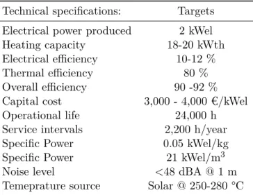
Nevertheless, few scientists investigate micro solar CHP plants, even less with latent heat thermal energy storage placed between the solar field and the power block. The basic plant solution consists of: (i) a Linear Fresnel Reflector (LFR of 80 kWth), (ii) a latent heat thermal storage (TES of 4h) and (iii) a micro Organic Rankine Cycle (ORC of 2 kWe). The system was designed for 250-300 °C, namely a reasonable temperature derived from technical and economical constraints.
The contribution in innovation of such micro CHP plant, leads to face up with many open research lines: (i) Phase Change Materials selection considering the toxicity, corrosion, stability after several thermal cycles, phase change temperature close to 250-280 °C, cost, thermal conductivity; (ii) heat pipes designed for withstand at mid-high temperature, ability to transfer heat into the storage medium; (iii) the maximization of the electric output of the micro ORC keeping a feasible cost; (iv) trying to find out novel rules to manage the energy system efficiently, maintaining high levels of reliability. Modeling solar ORC plants encompasses all the heat transfer problems, for example the most complicated ones regard the optical characterization of the LFR (far more complex than parabolic trough), or phase change: in the Heat Pipes, plate heat exchanger (ORC), phase change material etc. A trade-off between CPU burden and quality of the output results was found. For this purpose,ad-hoc subroutines for each subsystem were written in MATLAB and the numerical investigations accomplished to characterize the plant performance with the specific degree of accuracy. Particular attention was paid for modeling the dynamic behavior of most critical subsystems in order to increase the dynamic response fidelity of the system in light of the subsequent testing of the control system.
This dissertation shows the potential production of such kind of plants, for example with a mirror ground area of about 246 m2, in the city of Lerida (Spain), the annual electric and thermal energy production is about 6500 kWh and 58,800 kWh respectively. Preliminary numerical investigations showed high thermal losses of the pipelines, thus new mathematical models were developed to increase the precision of such results. Moreover, to reduce the wasted heat of the thermal storage,
vi
due to its low State of Charge level (unexploitable by the ORC) a novel strategy for the thermal management was presented, it was able to increase 5 % the annual energy production. Coupling the simulation system with a building is it possible to assess the influence of the user demand on the system performance. More precisely, an additional low temperature storage was added in bottoming to the ORC and the heat source was used for space heating and space cooling. Moreover, an absorption chiller was added to recover the large wasted heat in summer seasons. The new set-points of the ORC cooling water and the non-contemporaneity between the thermal source and the user demand was taken into account to quantify the coverage level from solar energy, and hence the extra cooling and heating power required from the vapor compression pump and boiler respectively. Basically, the optimal number of apartments was found to cover as much as possible the required thermal and electrical demand with RES. A further investigation dealt with the inner wall temperature prediction of the receiver tube in the solar field, by its knowledge the plant can be operated in safer conditions avoiding thermal stress and getting a more accurate thermal efficiency. Finally, a communication framework for testing the plant control Hardware with the in the Loop approach was developed. An external control board was connected to the simulated plant to optimize preliminary control strategies. This study allowed to significantly reduce the time spent in designing the control architecture.
Concluding, the numerical investigations here accomplished underlined to what extent the thermal losses are critical in such kinds of plants and how they can be accounted for with more accuracy. Despite the high plant complexity and cost, in the trigeneration configuration it can be a valuable alternative to integrate conventional space heating, cooling and domestic hot water systems. The simulated plant can considerably reduce the control system design by means of Hardware in the Loop technique.
vii
Ringraziamenti
Prendendo una citazione di Karl Popper: "le scienze esatte nascono per essere smentite", si può intuire come il processo di apprendimento non abbia mai fine. Abil-ità, preparazione, intuito, permettono di ottenere delle risposte, che fortunatamente (a mio parere) generano altre domande, dandoci la possibilità di affrontare sempre nuove sfide entusiasmanti alla scoperta del misterioso mondo che ci circonda.
Detto ciò, ringrazio il mio tutor prof. Emanuele Habib, che dal lontano 2010 ad oggi mi ha accompagnato in questo percorso di studi in Sapienza. Grazie ai suoi insegnamenti sono riuscito in qualche modo a migliorare l’approccio scientifico allo studio dei problemi, ad esempio migliorando notevolmente la qualità di alcuni studi che fin da subito sembravano avere poco valore scientifico, ma alla fine, dopo una attenta rielaborazione sono risultati invece molto interessanti. Grazie inoltre per avermi dato una mano sostanziosa a sbrigare le molte attività burocratiche, con le quali sono riuscito ad aggiudicarmi due bandi di avvio alla ricerca, mobilità del dottorato e l’accordo Erasmus+ con l’Università di Lleida.
Il prof. Enrico Bocci è stato un valido accompagnatore alla scoperta del mondo della ricerca insegnandomi davvero molte cose riguardo molteplici aspetti, a lui un grazie particolare. Difatti, se non avesse avuto fiducia nelle mie capacità non sarei qui a scrivere questo tema di ricerca che mi ha molto appassionato negli ultimi 4 anni.
Per quanto concerne invece il progetto Europeo a cui la mia ricerca si appog-gia, ringrazio la prof.ssa Alessia Arteconi ed in particolare il prof. Luca Cioccolanti. Abbiamo scritto davvero molti articoli scientifici insieme, mi hanno
trasmesso la metodologia necessaria per donare ai risultati ottenuti il loro reale valore nel relativo contesto di ricerca. Di non secondaria importanza invece è l’aspetto che riguarda il lavoro in team, le scadenze dei Work Packages del progetto EU hanno implicato ritmi serrati di lavoro, i risultati dovevano e devono essere programmati all’interno orizzonte temporale ben definito. Se a questo si aggiunge la collaborazione e l’interfacciamento con gli altri partners internazionali, si evince chiaramente come nel complesso, tutte queste attività mi abbiano arricchito anche dal punto di vista organizzativo e manageriale, rendendo il lavoro ancor più emozionante.
ix
Contents
1 Objectives 1 1.1 Main Objective . . . 1 1.2 Specific Objectives . . . 1 2 Methodology 3 3 Micro solar CHP: introduction and basic technologies 5 3.1 Transition to Renewable Energy Resources . . . 53.2 Review of concentrating Solar Power technologies . . . 13
3.2.1 Linear Fresnel Reflectors . . . 15
3.2.2 Parabolic Trough Collectors . . . 16
3.2.3 Parabolic dish . . . 17
3.2.4 Central tower . . . 17
3.3 Review of power conversion technologies . . . 19
3.3.1 Organic Rankine Cycle . . . 20
3.3.2 Stirling engine . . . 24
3.3.3 Kalina Cycle . . . 26
3.3.4 Goswami Cycle . . . 28
3.3.5 Externally fired micro-turbine . . . 31
3.4 Review of thermal energy storage systems . . . 34
3.4.1 Sensible heat storage . . . 35
3.4.2 Latent heat storage . . . 36
3.4.3 Thermochemical storage . . . 37
3.4.4 Comparison of thermal energy storage technologies . . . 38
4 Motivation for the micro CHP plant 41 4.1 Concept design of the micro CHP . . . 43
5 Outline of dissertation 51 6 System modeling 53 6.1 Linear Fresnel Reflector . . . 53
6.1.1 Introduction . . . 53
6.1.2 Modeling . . . 56
6.1.3 Wall-to-fluid heat transfer . . . 65
6.2 Latent Heat Thermal Energy Storage . . . 78
x Contents 6.3.1 Introduction . . . 80 6.3.2 Modeling . . . 81 6.4 Pipeline . . . 86 6.4.1 Introduction . . . 86 6.4.2 Modeling . . . 88
7 Dynamic simulation test cases 93 7.1 Global system performance . . . 93
7.1.1 Global energy evaluations . . . 93
7.1.2 Effect of the pipelines modeling . . . 105
7.1.3 Effect of the storage partialisation . . . 114
7.2 System performance evaluation in building integration . . . 127
7.2.1 Introduction . . . 127
7.2.2 Methods and modeling . . . 132
7.2.3 Building specifications . . . 134
7.2.4 Results and discussion . . . 137
7.2.5 Conclusions . . . 148
7.3 Wall temperature prediction of the LFR receiver tube . . . 150
7.3.1 Material and methods . . . 150
7.3.2 Results and discussion . . . 151
7.3.3 Conclusions . . . 154
7.4 Hardware-In-the-Loop aided control design . . . 156
7.4.1 Introduction . . . 156
7.4.2 Methods and modeling . . . 158
7.4.3 The hardware-in-the-loop framework . . . 165
7.4.4 Results and discussion . . . 167
7.4.5 Conclusions . . . 175
8 Conclusions and future works 179 8.1 Conclusions . . . 179
8.2 Future works . . . 182
A Simulink models 183 A.1 Solar generator . . . 185
A.2 LFR . . . 205
A.3 TES . . . 221
A.4 ORC . . . 225
A.5 Pipeline . . . 233
A.6 Tee and diverters . . . 239
A.7 controller . . . 242
B Empirical correlations for the LFR wall heat transfer coefficient 245
1
Chapter 1
Objectives
1.1
Main Objective
To develop a detailed numerical model for a micro solar Combined Heating and Power plant suitable for investigations about performance and control system design.
1.2
Specific Objectives
• Select a novel technology for a decentralized energy system as a cogeneration unit, using concentrated solar power for small scale building applications.
• Develop ad hoc sub-routines in MATLAB for each subsystem of the plant that accurately reproduces the dynamic effects of the plant.
• Create a basic communication architecture with the ModBus protocol under a Hardware in the Loop approach to enable externally control unit to be tested by means of the developed micro solar simulation model.
• Find an optimal control of the valves and pump installed in the plant to facilitate the plant commissioning in a real scenario when the prototype will be operative.
• Evaluate the thermal (heating and cooling) and electrical demand coverage for a multi-family house within a simulated environment coupling and external building model.
• Try to investigate the effects of the chosen control strategy aimed at managing the plant on the thermal stress of the solar receiver tube.
• Try to extrapolate from the simulated wall temperature of the receiver tube a new correlation in order to prevent thermal stress.
3
Chapter 2
Methodology
On the basis of the above defined objectives for this dissertation, the methodology followed for the present work can be divided into different stages. The well known Energy supply issues lead to study of new solutions to reduce the environmental impact, here is presented a novel technology whose challenge is overcoming the common barriers that prevent the implementation of micro Concentrated Solar Power systems at building level. Different solutions for the subsystems are selected even though some parts are not currently marketable products, indeed part of the research of this work intended minimizing this technology gap.
Secondary aspect concerns the development of a preliminary control strategy of the whole system aimed at maximizing the energy production and making its operation more stable and reliable. On this purpose, the technical specifications of the prototype under construction within the European project Innova MicroSolar are taken as a sample.
All the assessments to achieve the aforementioned objectives are summarized up next:
• Literature review: In this stage, the possible candidates technologies to build a micro Solar Combined Heating and Power systems (CHP) are compared and selected. Advantages and disadvantages of the current SoA (State of Art) technologies in energy conversion and storing are analysed, with particular regard to compliant with reliability and building integration requirements. The recent trends on the technology improvements provide the motivations behind the choice of each subsystem.
• System implementation: since the novelty introduced by this power system, and the detail level required for these studies, ad hoc subroutines are developed for each subsystem. The dimensional level of discretisation is chosen to highlight the dynamic behavior of the plant and the critical issues that may occur in such kinds of plants.
• System validation: despite the lacking experimental data, a careful examination of literature allows to validate the majority part of the mathematical models here accomplished with MATLAB code.
• System testing: many test cases are carried out aimed at investigating some performance parameters of the plant connected with a simulated building,
4 2. Methodology or with the purpose of improving the electric power generated reducing the thermal losses. Moreover, some analyses are conducted to outline the effect of the controller action on the parameters of the plant.
5
Chapter 3
Micro solar CHP: introduction
and basic technologies
Before to explain the concept design of the micro CHP, it is important to underline the research motivations behind which this study was undertaken, namely the global warming and the gradual transition towards Renewable Energy Resources. Said that, a brief survey on the current technologies for (i) energy production, (ii) energy storage, (iii) power production from a mid temperature hot source is addressed. A basic characterization and comparison of each technology is carried out, it is aimed at showing the main advantages and disadvantages in perspectives of an implementation in a solar microCHP plant.
3.1
Transition to Renewable Energy Resources
Energy has been the main industrialization driver for centuries, playing an important role in the generation of wealth. An example is shown in fig. 3.1 where the gross domestic product is compared with the CO2 emissions: countries begin in the
bottom-left of the chart at low CO2 and low Gross Domestic Product (GDP), and move upwards and to the right. Historically, where fossil fuels are the dominant form of energy, we therefore see increased CO2 emissions as an unintended consequence
of development and economic prosperity. In fig. 3.1 the CO2 emissions per capita are measured in tonnes per person per year. GDP per capita is measured instead in international $ (2011) prices to adjust for price differences between countries and inflation.
On the other hand, the global increase in the world’s population leads to higher energy consumption, the demand is expected to grow in the next decades.
At present, the International Energy Agency (IEA) [7] asserts that more than 80 % of the total primary energy derives from fossil fuels. The current massive use of fossil fuel promotes global warming. As a result the fossil fuel demand sharply increases as depicted is fig. 3.2 (annual CO2 emissions from different fuel types, measured in tonnes per year).
Coal is still used intensively in developing countries since its affordability and for supply reasons, China is one of the most consumer, the consequences are clearly visible in fig. 3.3.
6 3. Micro solar CHP: introduction and basic technologies
Figure 3.1. CO2emissions per capita Vs GDP per capita, 2016.
Source: Global Carbon Project, Maddison (2017).
Figure 3.2. CO2 emissions by fuel type, World.
3.1 Transition to Renewable Energy Resources 7
Figure 3.3. Total greenhouse gas emissions, 2016. Source: CAIT Climate Data Explorer via. Climate Watch.
Taking a closer look about the CO2 emissions share from fossil fuels, categorized
by sector in fig. 3.4 (including emissions from land-use change and forestry), it is worth to notice how the energy production has the most relevant impact on the total amount of CO2 emissions and directly on the global warming effect.
To face with the derived climate changes, the Intergovernmental Panel on Climate Change (IPCC) asserts a reduction of at least 50 % in the global CO2 emissions with respect to 2000 emissions has to be reached within 2050 to limit a long term global temperature rise predicted to be between 2.0 °C and 2.4 °C [64].
In 1987, started the concept of sustainable development with regard to the environment, the economy and society with the publication of the Brundtland Report [82]. The international Kyoto agreements of 1997 introduced an environmentally measured sustainability aspect to energy policy fixing the emission reduction targets [22]. The most recent Paris climate conference (December 2015) bound its adopters to a global agreement to limit global warming to below 2 °C [27].
The first impulse to a change towards the Renewable Energy Resources (RES) was determined by the fossil fuel crisis of the 1970s, which resulted in rising fuel prices and the realisation of the finiteness of fossil fuels. As a result, new energy technologies based on renewable energy resources, such as sun, wind and electricity-heat cogeneration, started to appear to increase self-sufficiency and security of supply. One of the biggest drawback concerns the rise in technical and economical challenges with respect to conventional power generation.
Figure 3.5 depicts the current energy share of different technologies, even if the hydropower is the largest, wind and solar energy are growing in the last decade with 8.8 % and 18 % respectively. Broadly speaking, RES are steadily becoming a greater part of the global energy mix, their penetration in the energy supply is
8 3. Micro solar CHP: introduction and basic technologies
Figure 3.4. CO2emissions by sector, World.
Source: CAIT Climate Data Explorer via. Climate Watch.
Figure 3.5. Renewable energy generation, world, 1965 to 2018. Source: BP Statistical Review of Global Energy, 2019.
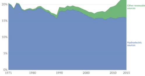
3.1 Transition to Renewable Energy Resources 9 increasing year by year as shown in fig. 3.6, they account for 22 % of the global share in electricity production1.
So far, many technologies have been studied, each one having its own advantages and disadvantages, but they globally have in common a lower energy density com-pared with conventional fossil fuels [177] which somehow reflects into higher costs and less competitiveness.
Figure 3.6. Share of electricity production from renewable sources, world, 1971 to 2015. Source: International Energy Agency (IEA) via World Bank.
Residential consumers in Europe are in line with the global trend in energy consumption, they are responsible for 30-40 % of the total energy consumption by sector [19], however the conventional power system infrastructure requires a redesign in light of the recent developing of these technologies in terms of cost and efficiency, thus being able to install them at residential level. Small-scale technologies located close to or at the premises of end-consumers in the grid (so called Distributed Energy Resources (DER)) are one example of developments in the residential sector.
In the last decade the research is addressed in integrating the RES with the grid, because the network is progressively becoming active, is a crucial point realizing an infrastructure that incorporates information communication techniques with physical devices to automatically collect and exchange data. This goal is reached with the smart grid that provides efficient, reliable, and cost-effective electricity power service to users via the integration of modern information and communication technologies in the traditional power grid [25]. Integrating distributed energy resources with energy storage devices using a smart grid can reduce the generation costs, smooth the curve of bulk power generation over time, reduce bulk power generation and distribution losses, and provide sustainable user service reliability [191]. Recent black out in the world have highlighted the weakness of centralized power generation, on the contrary, DER can decrease electrical network losses due to smaller scales and the absence of long-distance transmission networks. Moreover, cogeneration and trigeneration can be often adopted by means of small district heating networks,
1Other renewable resources includes solar photovoltaic (PV), wind (offshore and onshore),
10 3. Micro solar CHP: introduction and basic technologies while in the centralized power production, the investment cost can be affordable only in some cases where the users are enough close to the power block.
Among all the RES, solar energy is the most abundant one, its exploitation is very attractive, indeed only giving an idea concerning its potential: by a rough estimation 30 minutes of solar radiation impinging onto the earth’s surface is equivalent to the world’s energy demand for one year.
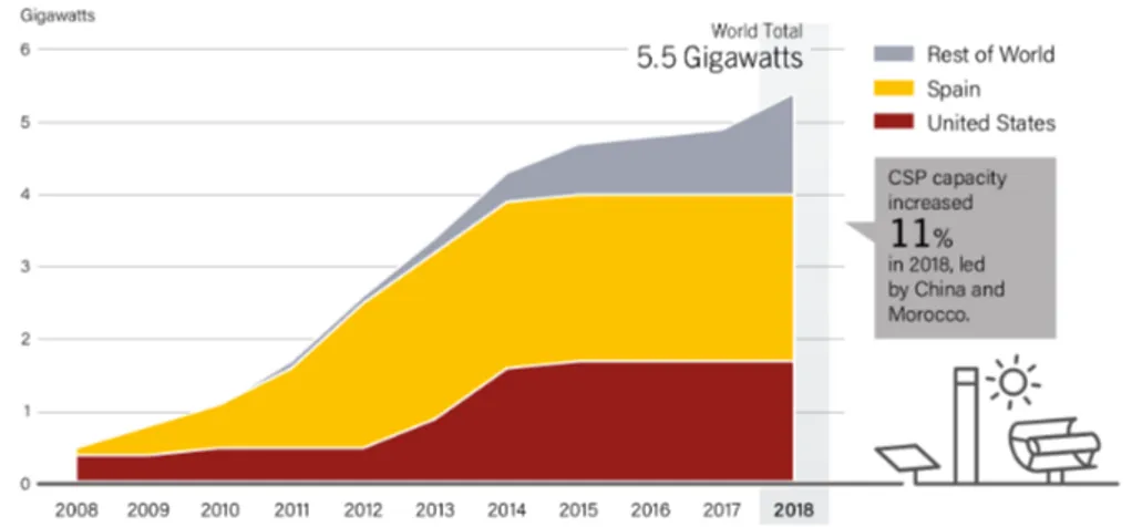
Photovoltaics (PV) and Concentrating Solar Power (CSP) are the two technolo-gies in rapidly growing, one worth parameter to estimate this trend is represented by the Cumulative PV and CSP power installed capacity during the years [114, 42], shown in figs. 3.7 and 3.8.One may observe, even though the cumulative installed capacity of PV is currently 2 order of magnitude higher than that of CSP, the growth rates during the last period have been similar for both technologies.
The PV investment costs are always lower than those of CSP. On the other hand, it must be taken into account that the load factor of CSP is higher than that of PV if storage systems are installed, which would decrease differences in LCoE (levelized Cost of Electricity) between PV and CSP becoming it often more financially viable. Alike of PV, CSP systems are more suited in areas where annual global irradiations are above 1300 kW-h/m2 . This is due to the fact that concentrating technologies can only take benefit of Direct Normal Irradiance (DNI), but not diffuse irradiance (as instead occurs in PV), which is predominant in cloudy and humid regions, typical of areas close to the equator. In addition, in high latitude regions the sunlight must cross a larger distance of the atmosphere that increases absorption and scattering, and thus increases diffuse irradiance.
Figure 3.7. Cumulative PV system installations from 2010 to 2019 estimates. Source: IEA 2019.
Resuming the concept of cogeneration and trigeneration, even if PV systems are suitable for DER, they can not provide heating or cooling directly, unless their electric energy is further converted by means of a heat pump or similar. Storing heat or electricity is highly costly for PV, while CSP are designed to do it.
3.1 Transition to Renewable Energy Resources 11
Figure 3.8. Concentrating solar thermal power global capacity, by country and region,
2008-2018.
Recently, to reduce the need for electrical storage and take advantage of the increasing efficiency and diminishing costs of PV, the US Department of Energy’s Advanced Research Projects Agency–Energy (ARPA-E) has created the Full-Spectrum Optimized Conversion and Utilization of Sunlight (FOCUS) program to link PV and CSP [4]. Spectral beam splitting in hybrid PV/T systems for power generation are some lines of research, but actually for long the main issue regarding CSP plants concerns the high cost at small scale. To figure out this techno-economic gap, the use of Combined Heating and Power plants (CHP) integrated in buildings can reduce from one side the current large CO2 emissions in electricity and heat (fig. 3.4), and from the other it can increase the RES penetration inside the network not only considered from an electrical point of view, but also in heating and cooling with district heating. At present, this transition is under study with the 4th generation District Heating networks [124] where all the RES mix interacts with the network for efficient heat supplying. Under these considerations, micro solar CHP technology can sustain the gradual transition towards DER, provided that significant progress in research and development is done, especially for thermal storage, which is still a challenge not only for the electrical one, but also in CSP applications if compactness and reliability are needed.
Phase change materials represent the most promising way to store heat effectively, they can store or release heat using the high latent heat capacity, thus increasing the specific energy per weight, but at the same time they allow to exploit heat at higher temperature, raising the electrical efficiency during the conversion.
In this dissertation the mathematical model of a micro solar CHP with a phase change thermal storage is investigated, in particular a performance assessment is carried out considering the integration at building level. Moreover, other studies are addressed to measure the impact on the performance with varying specifications of the plant, for example partializing the thermal storage. Other not secondary aspects of this research deal with control design and operation modality, in fact excessive thermal stress or not efficient work can arise if the plant is not properly controlled. The outcomes of this research provide useful information to the plant under construction in the European project Innova Microsolar [21], at the same
12 3. Micro solar CHP: introduction and basic technologies time scientific community can get the limitations and the potentiality of this kind of small scale solar CHP for future applications in Distributed Energy Resources.
3.2 Review of concentrating Solar Power technologies 13
3.2
Review of concentrating Solar Power technologies
Broadly speaking, solar field can be classified in four typologies [113] as depicted in figure 3.9: Linear Fresnel Reflector (LFR), Parabolic Trough Collector (PTC), Central Tower (CT) and Parabolic Dish Collector (PDC). Due to the fact that punctual collectors achieve higher concentration ratios than linear collectors, they drive the receiver to higher theoretical temperatures. That is to say, parabolic dishes and central towers attain higher concentrations than parabolic troughs and linear Fresnel Reflectors respectively.
(a) Parabolic trough collector (linear 2 D and
mobile receiver).
(b) Parabolic dish/Stirling engine (punctual
3 D and mobile receiver).
(c) Central tower technology (punctual 3 D
and fixed receiver).
(d) Linear Fresnel Reflector (linear 2 D and
fixed receiver).
Figure 3.9. Classification of solar field technologies.
Another aspect concerns the solar tracking, biaxial tracking systems can achieve higher concentration factors and efficiencies than those monoaxial, these latter are in turn preferable than static solar field (for example flat plate collectors). There are several reasons: firstly, shading and blocking effects are negligible or sometimes absent thanks to the fact that the whole reflecting surface of each collector moves as a rigid body. Secondly, the aperture is perpendicular to the impinging sunlight, which minimizes cosine factor losses. Main characteristics of the solar field technologies here presented are summarized below:
14 3. Micro solar CHP: introduction and basic technologies
Table 3.1. Comparison of the main solar technologies [163].
Parabolic Trough Solar Tower Linear Fresnel dish Stirling Typical capacity (MW) 10-300 10-200 10-200 0.025-0.1 Operating temper-ature (°C) 350-550 250-565 390 550-750
Plant peak effi-ciency (%) 14-20 23-35 18 30 Annual solar-to-electricity efficiency (net) (%) 11-16 7-20 13 12-25 Annual capacity factor (%) 25-28 (no TES) 29-43 (7 h TES) 55 (10h TES) 22-24 25-28 Collector concentration
70-80 suns >1,000 suns >60 suns (de-pends on sec-ondary reflector) >1,300 suns Receiver/ absorber Absorber at-tached to collec-tor, moves with collector, complex design External surface or cavity receiver, fixed Fixed absorber, no evacuation sec-ondary reflector Absorber at-tached to collec-tor, moves with collector
Storage system Indirect two-tank molten salt at 380 °C (dT = 100 K) or Direct two-tank molten saltat 550 °C (dT = 300 K) Direct two-tank molten salt at 550 °C (dT = 300 K) Short-term pres-surised steam stor-age (< 10 min) No storage for Stirling dish, chemical storage under develop-ment Cycle Superheated Rankine steam cycle Superheated Rankine steam cycle Saturated Rank-ine steam cycle
Stirling Steam conditions (°C/bar) 380 to 540/100 540/100 to 160 260/50 n.a. Maximum slope of solar field (%) <1-2 <2-4 <4 10% or more
3.2 Review of concentrating Solar Power technologies 15
The heat transfer fluid
The task to remove heat from the receiver and transfer it either to the storage system or to the final use (the power block) is accomplished by Heat Transfer Fluids (HTFs). They can be liquid, gaseous, depending on the applications, currently the
most used are: synthetic oil, molten salt, water, gases.
If operating temperatures below 400 °C are needed, synthetic oils or in general organic fluids, like for example Therminol VP1 or DowTherm are the most commonly choice, their thermal stability is kept in a wide temperature range, moreover, unlike the common oil it has been designed to maintain its thermal properties unchanged, such as viscosity and thermal conduction do not change too much with temperature. Thanks to these properties, the heat transfer coefficient is very good, while the pumping losses are kept low (per unit of energy transferred). It is worth saying that no high pressure tanks are needed, but in some conditions they can be flammable and a careful design during the construction phase must be paid for security reasons.
Molten salts are thermally stable up to 570 °C, thus are suitable for solar fields with high concentration ratio, they theoretically allow to obtain thermal efficiency very close to those in boiler power plants (the maximum temperatures are close to 600 °C). Unfortunately, they freeze and solidify at relatively high temperature, 220 °C for binary salts (mostly used due to their lower cost) and 120 °C for ternary salts. To maintain the power block operative, the lower temperature tank must be maintained at 290 °C, when the solar energy is not enough, fossil fuels are used in order to maintain the tanks above the minimum desired temperature.
Unlike the previous solutions, Direct Steam Generation (DSG) has the advantage to drive the steam turbines without additional heat exchangers, reducing the cost and complexity of the plant and increasing the global efficiency. Moreover, it is cheap and not flammable or toxic, however it requires a high pressure piping system and cannot be stored efficiently. The heat transfer coefficient is good during preheating, very high during evaporation and very low when superheating, thereby it implies that the evaporation in horizontal tubes can drive to different flow patterns causing thermal stress in PTCs, especially in the superheating process which occurs at high temperature and the HTF can not be effective in heat extraction. Nonetheless, the very low density of superheated steam leads to higher pumping losses.
Gases eliminate the temperature limits and generally do not have safety and environmental issues. Two main drawbacks hinder its massive use in solar plants: at parity of enthalpy jump, gases need high pumping energy and the heat transfer coefficient is not comparable to liquid fluids. To partially reduce this gap, pressurized gasses are used (20 bar or more) in open gas turbines.
3.2.1 Linear Fresnel Reflectors
The Linear Fresnel Reflector technology as depicts in fig. 3.10 concentrates the solar energy onto a receiver placed above the ground through a series of ground-based mirrors. The mirrors can be moved independently each other by means of a monoaxial tracking system, furthermore they are designed with a specific curvature able to approximate the ideal parabolic shape. Comparing to the PTC, the approximation of the parabola shape leads to a lower ideal optical efficiency, this aspect may be
16 3. Micro solar CHP: introduction and basic technologies improved using a secondary reflector. The use of ground-based mirrors allows cost reducing because of a lighter framework, moreover the fixed absorber does not need expensive rotating joints and a lower land occupation than PTCs. On the other hand, the above mentioned advantages have to face with the lower optical efficiency, the main inefficiencies of LFCs are due to shading and blocking, which affect differently mirrors depending on its location above the horizontal plane.
Figure 3.10. Schematic of a Linear Fresnel reflector.
3.2.2 Parabolic Trough Collectors
A PTC is a linear-focus solar collector, basically composed of a parabolic-trough concentrator that reflects the impinging sunlight onto a receiver or absorber tube located in the focal line of the parabola, see fig. 3.11.
Obviously they own a monoaxial tracking system and they are placed with a precise distance preventing the mutual shading and blocking effect, but this characteristic results in a bigger encumbrance if compared with LFRs. PTCs are the most popular CSP systems in the current development of solar thermal power, particularly in Spain, in fact they represent the biggest share of the world energy production via CSP. In order to maximize thermal efficiency, all receivers installed consist of an evacuated tube, with an outer glass envelope and an inner steel tube. The vacuum annulus permits not only the elimination of convective losses, but also the use of selective coatings with very high absorptivities in the solar spectrum while very low emissivities in the infrared spectrum. In addition to the use of selective coatings, the glass surface is treated with anti-reflective coating in order to enhance the transmission of the sunlight. It is of particular importance the potential leakage of thermal fluid through the rotating joints, they have to be designed to withstand at high temperature (above 500 °C) maintaining a good flexibility during the time. Due to the thermal expansion of the absorber tube, the adoption of bellows is necessary to avoid the failure of the heat collector element thus representing an important share of the Heat Collector Element (HCE) investment cost. Typically, large scale
3.2 Review of concentrating Solar Power technologies 17
Figure 3.11. Schematic of a parabolic-trough collector.
PTC has a constraint that limits the aperture dimension, i.e. the wind drag effect, as matter of fact the biggest parabolic trough has an aperture in the range 5.5 m - 6 m. The total length of a solar collector assembly reaches the value of about 100 -150 m, whereas the absorber tube length is usually limited to a value of 4 m because of mechanical bending.
3.2.3 Parabolic dish
It consists of a parabolic dish that is perpendicular to the sunlight at all times, thus it is equipped with a two-axes tracking system, concentrating solar rays to the optical focus where the receiver is located. The simple schematic of the parabolic dish is depicted in fig. 3.11.
Generally, either a Stirling engine or an open air gas turbine is usually placed at the focal length. Thanks to its geometry, high concentrating factors are achievable by this technology, i.e. up to 4,000 suns, which permits to heat up HTFs up to 1000 °C. As a result, solar dishes can achieve the maximum solar to electricity efficiency, around 30% tab. 3.9; it must be noted that such a range of efficiencies was already obtained during the 1980s. This demonstrates that efficiency is not a key feature of CSP plants. Most parabolic dish modules generate nominal powers from 10 kW to 25 kW, i.e. with diameters up to 10 m, therefore they are not suitable in large centralized fields. As occurs in PTCs, the wind drag effect implies higher structural straightness, and thus higher costs. Another important drawback is the absence of energy storage, as a consequence it makes them compete directly with PV modules.
3.2.4 Central tower
As in parabolic dishes, Central tower is equipped with a two axial tracking system, but it is made up of a set of heliostats placed over the ground, which are spaced in
18 3. Micro solar CHP: introduction and basic technologies
Figure 3.12. Schematic of a parabolic dish.
a field to avoid mechanical or optical interference. Moreover, they have a pivot to reflect incident direct-beam sunlight onto an elevated receiver or secondary reflector located in the center of the solar field as shown in fig. 3.13.
Figure 3.13. Schematic of a central tower.
CT has the advantage of locating the receiver in one only "point" of the field, which greatly reduces the thermal losses due to the higher compactness of the power system at elevated temperature. In addition the HTF is pumped only in a narrow region close to the power block reducing the pumping losses. Sometimes, the heliostats instead of surrounding the receiver are placed only on one side. There are several factors that affect the CT optimal size:
• as the size of the solar field rises, the distances from mirrors to receiver increase as well, as a result hitting the target is a problem and ray distortion by atmospheric effects (hot air lenses) hampers the achievement of good focusing onto the receiver;
3.3 Review of power conversion technologies 19 • at larger distance, mirrors need a more precise construction and a more
sophisticated tracking system to hit the target;
• at higher concentration ratios the flux rises, though a reduction in the receiver surface is beneficial regarding the thermal losses, it implies higher costs due to higher thermal constraints;
3.3
Review of power conversion technologies
In this section the main power conversion technologies are compared to highlight advantages and disadvantages relating to the micro CHP applications. The power block converts a fraction of the thermal energy in input to electricity, the previous described CSP technologies achieve temperatures between 300 °C and 1000 °C, which are commonly exploited by thermodynamic power cycles in combination with fossil fuels or geothermal. Even though combined power cycles (made up of gas turbines in series with steam Rankine cycle) are used in large power plants providing electric efficiency close to 60 % at the nominal conditions, at small scale other solutions have to be found. Open-cycle or closed-cycle turbines are neither technically nor economically beneficial, it depends from case to case. Before to discuss the main power conversion technology the fig. 3.14 deserves attention. For low power applications the ORC and the Stirling cycles are the most effective in power conversion, but ORCs are more indicated for low temperature waste heat recovery. Kalina cycle and Steam cycle are preferred at high power applications, even if the first one has applicability also at kW scale. Currently, CO2 cycle and
Flash cycle are the most advanced technologies studied, they cover low and high grade waste heat recovery suitable for middle size power plants. The Brayton cycle with an open gas turbine is not shown in the fig. 3.14 [121], but it can be stated that all the power out plane, with more than 500 °C can be entirely covered by regenerative gas turbines.
Figure 3.14. Main technologies fields in the heat source temperature-power output plane.
Organic Rankine Cycle (ORC) can be a valuable substitute of steam cycle at low temperature applications. Indeed, the broad variety of the refrigerants allow
20 3. Micro solar CHP: introduction and basic technologies the designer to choose the correct one to maintain the maximum working pressure below 30 bar and the dry saturation curve which does not require additional vapor superheating to prevent droplets in turbine. Maintenance requirements for ORCs are extremely low, unlike steam the working fluid is non-eroding and non-corroding for valve seats tubing and turbine blades allowing for long operational life, as a result the operation can be extended over 80,000 hours. Currently, the ORC technology is the most mature for small scale power plants and they are installed in CSP or recovering waste heat from industrial processes, with an interesting payback period. Stirling engines were used in world war 2, since their low noise, moreover thanks to the external combustion, emissions such as NOx, CO, can be significantly reduced.
They have good thermal efficiency and low maintenance. Despite these advantages, many companies involved in the production of such systems no longer exist. Other alternatives more advanced under research and development are the Kalina cycle, the Goswami cycle and the micro (air) gas turbine. Unlike ORCs, Kalina cycle is more indicated for very low temperature heat sources (around 100 °C), because of its binary mixture properties, in fact during the evaporation a glide occurs giving the possibility to extract more heat and reducing the irreversibilities associated with it [132]. Despite this valuable feature the Ammonia solution used into the cycle fixes the maximum operating pressure, thus the benefits mentioned cannot be technically achieved over 250 °C. The Goswami cycle has the same range of applicability of Kalina cycle since it uses the same binary mixture, the difference consists of providing not only power, but also a cooling effect typical of the ammonia absorption chillers. The electrical efficiency is greater than the ORC technology, but is still in the research phase, whereas nowadays there are some examples of commercial power plants running, for instance the power plant of 3.6 MW commissioned in 1999 by Sumitomo Metal Industries. Finally, the micro gas turbine driven with solar dish is another promising technology recently tested by ENEA [14] in the European project Optimised Microturbine Solar Power system (OMSoP) able to convert 70 kWth of radiant power to 15 kW of electric power. As already said a parabolic dish has a high concentrating ratio, hence the turbine inlet temperature can reach 800/900 °C.
3.3.1 Organic Rankine Cycle
The steam Rankine cycle can not work properly below 2 MWe [99], under that size the investment cost sharply rises making it no longer competitive with Organic Rankine cycle. Basically, for low temperature resources below 370 °C, thermal efficiencies also decrease to the point where steam cycles are no longer cost effective or efficient [109, 174]. The basic, ideal Rankine cycle begins with saturated water at state 1 pumped to a high pressure at state 2 and then heated isobarically to superheated steam at state 5. The superheated steam can then be expanded to state 6 through a turbine to generate power and then condensed back to saturated water at state 1. To improve the thermodynamic efficiency an additional heat exchanger is added to recover the waste heat from the turbine, state 6-7 to preheat the fluid before the evaporator state 2-3. in figure 3.15 is depicted the base scheme of an ORC unit and its T-S diagram with colored lines from red (high temperature) to blue (low temperature), while the heat source and cold source lines are placed above and below the cycle respectively based on the efficiency of each heat exchanger.
3.3 Review of power conversion technologies 21
Figure 3.15. Schematic of a regenerative ORC and its T-S diagram.
Research is mainly focused on working fluid selection, because the performance and the environmental impact are strictly bonded to it. Currently, the desirable organic fluid should have a positive isentropic saturation vapor curve (dry), preventing the turbine from damaging. A low viscosity and a large saturation curve reduces the flow rate and the friction viscosity, reducing the pump losses significantly. To work at high temperature a good thermal stability is required, but possibly at feasible evaporating pressure (below 30 bar). From the environmental point of view they should have a low Ozone Depleting Potential (ODP), low Global Warming Potential (GWP) and High safety level (no toxicity or flammability). Even though many fluids are studied for scientific purposes, actually only few of them are used in commercial plants. For low power applications the subcritical cycle is dominant, unfortunately the electric efficiency rarely goes beyond 16 %, while in small scale plants (10 kWe) are usually half. Among all the cycle configurations, ORCs can be classified in three categories: pure fluid subcritical, zeotropic and transcritical, an example of the T-S diagram is shown in fig. 3.16.
One of the major sources of irreversibilities for ORCs stem from the heat addition process. The thermal energy source and working fluid must be separated by some temperature difference in order to heat transfer occur; however, heat transfer across a finite temperature difference inherently causes irreversibilities. Therefore, it is important to maintain good temperature matching between the heat exchanger streams to minimize these types of irreversibilities [178]. Alongside the HTF fluid path, in countercurrent flow direction there is the working fluid which is first heated as a liquid, then it undergoes to liquid-vapor phase change, and if necessary, is further superheated as a vapor thereafter. This process causes a pinch point formation, reducing heat exchanger effectiveness, and destroying potential work or exergy. The exergy destruction caused by temperature mismatching can be qualitatively seen as the area of the plot between the thermal energy reservoir and working fluid stream in fig. 3.17. The worst behavior is given by the single component ORC, while
22 3. Micro solar CHP: introduction and basic technologies
Figure 3.16. Plant schematic and T-S diagram for basic pure fluid ORC, zeotropic Rankine
cycle, and transcritical Rankine cycle [104].
some roof of improvements are obtained in transcritical regime, where "wet" fluids perform better than "dry" [196], zeotropic fluid instead are the more attractive since their temperature mismatch is considerably decreased, the same principle used in the Kalina cycle and Goswami cycle in the next sections. Another solution to the pinch point problem can be a multi pressure boiling, but it introduces a noticeable complexity to the power plant, this solution is used only in large steam Rankine cycles that are outside the purpose of this dissertation. Finally, flash cycle in fig. 3.17 configuration enables near perfect temperature matching to the fluid stream from the finite thermal energy source.
Figure 3.17. Variation in stream temperatures during heat addition process for single
component(a), zeotropic (b), transcritical (c) and flash cycles (d)
3.3 Review of power conversion technologies 23 such as axial turbine expanders and the volume type, such as screw, scroll and reciprocal piston expanders. Turbine is more indicated over 100 kWe [99], whereas screw expanders cover the range around 100 kWe, finally scroll is more indicated around 10 kWe or below. Selecting an expander for a specified application is not straightforward, many important parameters have to be taken into account: such as high isentropic efficiency, pressure ratio, power output, lubrication requirements, complexity, rotational speed, dynamic balance, reliability and cost. On the basis of the above mentioned parameters, one can summarize the two types of expanders as shown in the tab. 3.2.
Table 3.2. The comparison of various types of expanders suitable for ORC system [57].
Type Capacity range (kW) Rotate speed (rpm)
Cost Advantages Disadvantages
Radial-inflow turbine
50-500
8000-80,000
High Light,weight, mature
manufacturability and high efficiency
High cost, low effi-ciency in off-design conditions and can-not bear two-phase Scroll
expander
1-10 <6000 Low High efficiency,
sim-ple manufacture,
light weight, low
rotate speed and
tolerable two-phase
Low Capacity, lubri-cation and modifica-tion requirement
Screw expander
15-200 <6000 Medium Tolerable two-phase,
low rotate speed and high efficiency in off-design conditions
Lubrication require-ment, difficult manu-facture and seal Reciprocating
piston
ex-pander
20-100 - Medium High pressure ratio,
mature manufactura-bility, adaptable in variable working con-dition and tolerable two-phase
Many movement
parts, heavy weight,
have valves and
torque impulse
Rotary vane expander
1-10 <6000 Low Tolerable two-phase,
torque stable, simple structure, low cost and noise
Lubrication require-ment and low capac-ity
For small scale applications, one can evince by the previous statements that due to the cost and efficiency constraints, subcritical cycle is often used at low temperature in combination with scroll expander. Actually, many researchers in literature have tried to find new solutions to push the technology beyond its limits regarding for example the expanders or exchangers, see tab. 3.2. In the first case, for instance Tomasz Z. [115] experimentally studied a new microturbine of 2.5 kWe able to reach 71 % of isentropic efficiency at 22,440 rpm, while conventional turbines efficiency usually work at 40 - 50 % (at parity of power output). Concerning the heat exchangers, if a low temperature source is used (around 100 °C), the solution found by Ruiqi Wang et. al [183] its interesting, because by means of a thermal
24 3. Micro solar CHP: introduction and basic technologies driven pump they increased the exchanger efficiency from 45.8 % to 51.3 % when the evaporating temperature increases from 75 °C to 100 °C. On the other hand, this solution is able to reduce the exergy destruction previously described in fig. 3.17, leading it to 62 %, when a conventional ORC attains to 59.9 %. Another interesting feature concerns the lower cost and better compactness than conventional heat exchangers, very useful characteristics for small scale targets applications.
3.3.2 Stirling engine
Originally invented in 1816 by Robert Stirling, at that time, these engines competed with steam engines because of their safety, in fact these latter requires strength materials to withstand high pressure, they sometimes exploded injuring nearby workers. Concerning the construction framework, three different typologies can be identified: alpha, beta and gamma as reported in fig. 3.18, in all the cases there are two chambers, one in the hot side and another in the cold side and a regenerator placed between them.
Figure 3.18. Three basic mechanical configurations for Stirling engine.
Particular feature of this engine consists of using an external heat combustion chamber, this makes it capable of using a wide variety of heat sources, for example biofuels, without fouling issues in the combustion chamber or contamination of the lubricant. Moreover, it is silent, not much vibration are generated from its motion unlike internal combustion engines where a fast combustion takes place.
From the thermodynamic point of view, it is worth to say that Stirling engine is able to potentially accomplish a cycle with the Carnot’s efficiency, in addition it
3.3 Review of power conversion technologies 25 can generate even more work. More precisely, the idealized Stirling cycle consists of four thermodynamic processes acting on the working fluid in fig. 3.19: (i) an isothermal heat addition (expansion), (ii) isochoric heat removal (constant volume), (iii) isothermal heat removal (compression), (iv) isochoric heat addition (constant volume). Actually, the real cycle is slightly different because of the not perfect regeneration (the regenerator has a limited heat exchanger effectiveness), the real gas effects and the impossibility to involve all the fluid in the thermodynamic cycle (part of it does not participate because of its construction constraints). In light of these considerations the fig. 3.19 shows also the (inner) real cycle based on the crank shaft position of a gamma and beta Stirling engine, obviously the real cycle significantly reduces the conversion efficiency of such technology. Ranieri et. al. [156] carried out a detailed analysis on the thermal efficiency reduction above mentioned. At their given temperature of the hot and cold source, the ideal cycle in alpha type Stirling totals 61.5 % in thermal efficiency (same of Carnot cycle), whereas the sinusoidal cycle achieves 34.4 %, which corresponds to a reduction of 27.1 % from the maximum attainable efficiency. The beta and gamma-type Stirling engines are slightly affected by the thermal efficiency reduction, with a 25.7 %.
Figure 3.19. Sinusoidal and ideal cycle plots in (a) P-v and (b) T-s diagrams for the beta
and gamma-type Stirling engines.
Nowadays, biomass-fuelled and dish Stirling engines can be considered the most studied and commercialized versions of this technology, Ferreira [89] compared an alpha-Stirling engine supplied with these two RES with a simulation analysis. The biomass-fuelled Stirling engine provided 87.5 % more power output than the solar energy source. It provides a power output of 4.3 kWe with a total efficiency of 46.67 %, whereas the solar system results in a system with 2.30 kWe of power with an efficiency of 31.33 %. Also, the average receiver temperature from the solar source is about 775 K, whereas, in the boiler bed, the temperature reaches the value of 1288 K. These results show that the energy source plays an important role and results in different engine performances. The lower efficiency reflects also in greater LCoE for the solar-power system: about 0.166 €/kWh, against 0.109 €/kWh of
26 3. Micro solar CHP: introduction and basic technologies the biomass-fuelled system. Broadly speaking, because Stirling engines are capable to operate with high temperature heat source between 800 °C and 1250 °C, as a consequence their conversion efficiency is relatively high if compared with the other systems described in the dissertation, this is the reason why solar dish is more indicated among the CSP systems from this point of view. One of the most efficient Stirling engines ever made was the MOD II automotive engine, it reached a peak thermal efficiency of 38.5 %.
Ferreira [89] did also a literature survey regarding the small and micro-scale biomass-fuelled CHP systems suitable for applications in domestic buildings. One can evince that hardly any of the electric power output exceeds 35 kW, commercial Stirling engines size for micro-CHP using biomass ranges around 2-3 kWe.
The characteristics both in thermodynamic and operation are somewhat at-tractive for a stationary power generation in DES, unfortunately there are many drawbacks that prevent a wide diffusion. For example, the real engine will always have some leakages, however small. If using air as the working gas you must have a small compressor to maintain engine pressurised. To reach high thermal efficiency, hydrogen or helium should be used, both the gasses have a strong tendency to be dispersed, especially the hydrogen which has a remarkable diffusivity coefficient in high pressure steel vessels. Just to give an idea: in the best scenario, steel diffusivity coefficient accounts for about 10-9(m2/s) at room temperature [88]. This means that for a steel vessel with 1 square meter surface area, 1 cm thick walls with 200 bar pres-sure difference, the diffusion rate is: J = (1 ·10−9·(200·44.5/0.01) = 0.00089[mol/s], that is to say 0.15 kg/day. Moreover the diffusivity rises at higher temperature climbing about 2 orders of magnitude to 10-5(m2/s) at 1000 K. As hydrogen diffuses through the container material, it occasionally forms bonds with the iron atoms, transforming the iron into a different molecular structure, and in the process it changes the crystal structure (decarburization, intergranular fissuring, or blistering) with additional boundaries or dislocations. Over a long period of time this lowers the maximum elastic stress and thus toughness of the steel, this phenomena is called hydrogen embrittlement. Composite tanks are much lighter than steel or aluminum for the same amount of storage, but they have even worse leakage properties. When using biomass as heating fuel for the heater (such as wood chips or switch grass), one must be careful of ash buildup on the heater tubes. The airborne ash can melt due to the high temperature, and form an insulating layer on the heater tubes, preventing heat from getting through reducing the performance. From the experimental tests carried out by Ferreira [89] is clear that a radiative heat exchange has to take place in order to make the heat transfer rate more effective, this is not simple to accomplish in a real test bench as it is mentioned. Also the automotive applications failed because of the time lag between the power request and that one provided to the user, only in the naval sector there are some existing applications.
3.3.3 Kalina Cycle
The Kalina cycle was invented by Russian engineer Alexander Kalina in 1983, it was considered as a worthwhile alternative to the conventional steam Rankine cycle applied in combined power plants as a bottoming cycle. The conventional version of the Kalina cycle uses a 70%/30% ammonia/water mixture as the primary
3.3 Review of power conversion technologies 27 working fluid, in fact the mixture composition affects the thermodynamic and the transport properties of the mixture. Since its introduction, several uses for the Kalina cycle have been proposed in the literature for low temperature applications. At high temperature, the chemical corrosion and the ammonia decomposition reduces its applicability. As already stated, the zeotropic mixtures allow to reduce the unavoidable irreversibilities during the evaporation fig. 3.20b, in addition, the use of mixture instead of a pure fluid gives more degree of freedom in terms of varying the mixture composition in order to obtain better performance from the power cycle. There are several plant configurations of the Kalina cycle, each one designed for a specific purpose, here as follows in fig. 3.20a is illustrated the basic version:
(a) Schematic of the Kalina cycle for low
temperature applications.
(b) Temperature profile comparison between
ORC and Kalina cycle.
Figure 3.20
From the schematic in fig. 3.20a it is possible to identify all the components of the Kalina cycle, i.e. a turbine (TUR), a generator (GEN), a low temperature recuperator (LT-RE), a high temperature recuperator (HT-RE), a condenser (CD), a pump (PU), a separator (SEP), a throttle valve (THV), a mixer (MX), and an evaporator (EV) with an external heat source which could be a waste heat stream, geothermal brine, etc. This configuration is used for low temperature applications and the ammonia rich vapour from the separator outlet is directly fed to the turbine. In this cycle the superheated ammonia-water mixture (stream 1), i.e. the working solution, expands in the turbine and is subsequently mixed in the mixer MX with the ammonia lean liquid from the separator SEP to lower the ammonia mass fraction in the condenser CD. When liquid anhydrous ammonia is dissolved in water, heat
28 3. Micro solar CHP: introduction and basic technologies is liberated (enthalpy of dissolution), thereby it is recovered from the stream 3 by means the low temperature recuperator, while the high temperature exchanger allows the temperature of stream 10 to fall before the mixing in MX.
Regarding the applicability in CSP plants, A. Modi et. al [134] presented a thermoeconomic optimization of a Kalina cycle designed for a net electrical power output of 20 MW with a turbine inlet temperature of 500 °C supplied by a PTC. At the design point, they assumed a turbine isentropic efficiency of 85 %, while the pumps totaled 70 %. In this analysis they compared the Kalina cycle with a steam Rankine cycle at the same size, they modeled the part-load conditions due to the solar source variation throughout the day, and all through the year. Finally they tried to optimize by means of optimization algorithms the thermodynamic cycle to reduce the LCoE. Despite the minimization of the levelized cost of electricity, their simulations resulted in the levelized costs of electricity between 212.2 $ /MWh and 218.9 $/MWh. For a plant of the same rated capacity, the state-of-the-art steam Rankine cycle has a levelized cost of electricity of 181.0 $/MWh. These outcomes stem from two factors (i) worse power cycle efficiency than the corresponding steam Rankine cycle configuration resulting in a larger solar field requirement for the same net electrical power output, and (ii) the higher capital investment cost for the power cycle itself. All in all, the results reflect the same statement previously said, i.e. it is not beneficial to use the Kalina cycle for high temperature concentrating solar power plants.
Y. Wand et. al [184] compared the Kalina cycle and ORC with a given temperature source of 80 °C, 120 °C, 180 °C, considering a multi-stream waste heat composite curve divided into three typologies: straight, convex and concave. In this way is simulated an industry process with multiple waste heat streams and different heat capacity flow rates, for example: if the curve is concave the heat capacity flow rate with lower temperature is greater than that with higher temperature. The shape of the curve, thus the area between the hot and cold composite curves provides an indirect measure of the magnitude of exergy loss during the heat exchange between the waste heat and the working fluid. Thanks to the zeotropic effect they claim that in all the cases of all the three kinds of waste heat, the waste heat recovery efficiency (recovered heat divided by the total waste heat) of the Kalina cycle is higher than that of the ORC. Anyway, they identify two key features with relating to the most suitable application, i.e. the concave/convex degree and the position of the most (salient or concave) point, this means that there is not a technology better than another one, the solution should be tailored on the specific application. Despite its complexity, presently, the Kalina cycle is second only to the ORC in terms of popularity in actual implementation and it is seen as the primary alternative to the ORC.
3.3.4 Goswami Cycle
In 1995, a novel thermodynamic cycle was proposed by Goswami, this system is still in the early stage of development. It uses an ammonia–water binary mixture as the working fluid, but unlike Kalina cycle it produces both power and refrigeration simultaneously. This cycle combines a Rankine and an absorption refrigeration cycle, the schematic is shown in fig. 3.21, and as ORC and Kalina it is suitable
3.3 Review of power conversion technologies 29 as a bottoming cycle using waste heat from conventional power cycles or as an independent cycle using low-temperature sources such as solar and geothermal energy.
Figure 3.21. Schematic of the Goswami cycle [85]
the main advantages in adopting this cycle are summarized as follow:
• Can be designed for all power to all cooling and any combination of power and cooling.
• Thanks to the zeotropic mixture it overcomes the irreversibilities associated with the pinch point in the evaporator.
• Condensation is made by absorption, thereby the turbine expansion is uncon-strained by the ambient air temperature, thus extending the recovered energy of the working fluid.
• Better energy source utilization if the cooling and power are produced sepa-rately.
• If all power is produced, because the heat of condensation is generated during the absorption in a separated site, it can be more easily released in the environment.
At first, the base solution (stream 1) leaves the absorber as saturated liquid at the cycle low pressure and then it enters the pump where its pressure is increased to the system high pressure (stream 2).
30 3. Micro solar CHP: introduction and basic technologies Secondly the fluid recovers heat from the returning weak ammonia liquid solution and then it enters the boiler (stream 3).
In the boiler, the basic solution is evaporated through a rectifier to split the vapors in a weak ammonia liquid, with a high concentration of water, and a rich vapor with a very high concentration of ammonia. In the separator, the two phase mixture is separated with an additional cooling stream and the weak liquid (stream 9) enters the recovery heat exchanger. The poor solution (stream 10) is then throttled to the system low pressure side and it is sprayed into the absorber (stream 11) releasing heat.
After that, in the rectifier, a cold stream (spilled for example by the stream 3) cools down the saturated rich ammonia vapor (state 5) to condense out any remaining water. The ammonia stream of state 5 can be superheated (stream 6) before entering into the expander where the fluid reaches the low-pressure side (stream 7). If the expander does not extract all the power from the stream 6, the temperature of the stream 7 can be significantly lower than ambient temperature and it can provide cooling output in the refrigeration heat exchanger (stream 8). Finally, the ammonia vapor rejoins the poor solution in the absorber rejecting heat, as a result the basic solution is regenerated again.
To give an estimation of the Goswami cycle potential, it can be compared with the most utilized cycle described in the previous section, namely ORC and the ideal Carnot in the same conditions at low temperature source. For a given boiler temperature of 400 K at 30 bar, and a condenser/rectifier temperature of 360 K, a superheater temperature of 410 K and fixing a turbine exit pressure of 2 bar, the tab. 3.3 shows the performance comparison. Starting from a heat source of 421.6 kW/kg it is able to produce 76 kWe/kg and a refrigeration output of 25.9 kWth/kg. It is noteworthy that the evaluation of the first law of efficiency is not as straightforward as one can think, due to the fact that there are two different simultaneous outputs, namely power and refrigeration. Vijayaraghavan together with Goswami, D. Y. in their study [179] delineated the first law and second law of efficiency for the combined cycle based on existing definitions in the literature.
Table 3.3. Performance comparison of the Goswami cycle. cycle first law efficiency
Goswami 20 %
Rankine 16 %
ideal Carnot 31.7 %
in this study [122] is possible to understand how the Goswami cycle responds in off-design conditions. They vary the hot and cold source temperature, or the ammonia flow rate inside the cycle to show its behavior. For example, at a fixed hot source temperature of 360 K, the initial refrigeration temperature of 265 K is allowed to let it down for steps of 10 K until no power is produced by the cycle. Both first and second law efficiencies increase slightly at first, then they drop monotonically, showing that there is an optimum refrigeration temperature, in this case 245 K. The first law efficiency has a maximum of 17.41 % and the second law efficiency has a maximum of 63.7 %, a very good achievement for an ambient temperature of 290 K


![Table 3.2. The comparison of various types of expanders suitable for ORC system [57].](https://thumb-eu.123doks.com/thumbv2/123dokorg/2885002.10752/33.892.131.741.380.873/table-comparison-various-types-expanders-suitable-orc.webp)