Dipartimento di Ingegneria Aerospaziale Tesi di Laurea in Ingegneria Aerospaziale
Development of a Multi-Physics model of a Civil
Aircraft for Ground Manoeuvres using Modelica
Relatori
Prof. Ing. Eugenio Denti Prof. Ing. Attilio Salvetti Ing. Daniele Fanteria Ing. Sanjiv Sharma
(Airbus UK)
Ing. Gianluca Verzichelli
(Airbus UK)
Candidato Serena Simoni
ANNO ACCADEMICO 2006 − 2007
c
AIRBUS UK LIMITED 2007 ALL RIGHTS RESERVED
The copyright in this document, which contains information of a proprietary nature is vested in Airbus UK Limited. The contents of this document/tape/disk/CDROM may not be used for any purposes other than for which it has been supplied and may not be reproduced either wholly or in part, in any way whatsoever, nor may it be used by, or its contents divulged to, any
Aircraft systems have become progressively more mechatronic and the interactions be-tween these systems are complex in nature. The objective of the approach followed in this work is to provide means to navigate through the complexity of these systems. In particular the project aims to develop a modelling paradigm that supports model reuse. Therefore the main thesis of this report is that the use of model-based engi-neering to support timely design decision, agility in producing design information is key. Further, to have an agile process, reusable modelling components are necessary. The main research question is therefore, “how can Modelica be used as a means for representing reusable model-components at different levels of granularity to support an agile model-based design process?”.
In this report the capabilities of an object-oriented language, Modelica, are investigated in developing reusable library components. The component-models derived are acausal parametric objects. These have been reused in developing a complex model of a large civilian aircraft and its associated hydro-mechanical steering systems.
Modelica’s acausality and object-oriented nature are features that help in the develop-ment of library components. By following the systematic approach described in this work when developing such model-components, the components at different levels of granularity can be reused and this may aid will lead to agility in the analyses of the design process. The object-oriented features of Modelica are explored as a means for navigating through the complexity of a design.
I would like to thank Prof. Eugenio Denti, Prof. Attilio Salvetti and Ing. Daniele Fanteria from Dipartimento di Ingegneria Aerospaziale “L. Lazzarino”, Universit`a di Pisa, for giving me the opportunity to prepare this thesis at Airbus UK. A special thank to Prof. Giovanni Mengali for his advices. I would also like to express my sincere gratitude and thanks to Sanjiv Sharma and Gianluca Verzichelli, Airbus UK, for supporting me during my work. A special thank to Sanjiv Sharma. I found him not only a fantastic tutor, but also a great person and I would like to thank him for carefully reviewing this thesis, for his support, for the many ideas that he gave to me during the development of this work and for always trying to let me think in terms of new directions to explore.
I would like to express my sincere gratitude to Airbus UK Limited for the opportunity of carrying out this work within their facilities.
I wish to thank Mr. Mike Dempsey from Claytex for technical support.
A true special thanks to the ones of my team who supported me and provided their feedback during this work: Franco Calvanese, Leonardo Vivarelli and Luke Bagnall. I wish also to thank the ones who helped me during my work in Airbus: Luke Spencer, Etienne Coetzee, Bjoern Kirchhoff, Linda Agoudjil and Terry Frost.
I would like to thank all my friends that shared with me the university years.
A special thanks to the ones I love: to my parents for the love and their patience they always gave to me, to my sister, for always being with me, to Adelma for her constant moral support, to Paolo for being like a brother for me.
Initially applied to the analysis of dynamical systems, historically with a Control Theory focus, Modelling and Simulation has now been embraced by a much wider community (Financial, Operational Research, Artificial Intelligence, etc.). This may be partly at-tributed to the rapid increase in computing power, but also to the development of generalised modelling approaches. Whilst the interest in modelling of physical systems has remained high, since the 1990s the modelling of non-physical systems (computa-tional, informa(computa-tional, etc.) has progressively grown. Now the engineered systems tend to integrate the different physical systems and non-physical systems, not as systems in their own right, but as system-elements of a mechatronics system.
In 2006 (Vivarelli, 2006), we reported on the Static Modelling encompassing the differ-ent aspects of a mechatronics systems, and showed how SysML could be used provide a multi-discipline design description. In this thesis, we report on the use of the object-oriented language, Modelica, for Dynamic Modelling of physical system-elements, again providing a multi-discipline design perspective.
Our starting point was to support design-making by predicting systems performance through modelling and simulation. During the early phases, candidate concepts need to be analysed, and with the information thus gained, the promising concepts are evolved. This process needs to be rapid, hence the modelling and simulation analyses needs to be agile. The first hypothesis, therefore, is that re-use of model-components are needed for an agile modelling and simulation process.
With this hypothesis, questions arise about:
• the characteristics that the re-usable model-components need to exhibit, • the way that the model-components should be published,
• the origins of the model-components, • the management of the model-components,
In this report the author sets the context and provides answers to these questions, through the use of engineering examples.
Sanjiv SHARMA 29 May 2007
The thesis is organized in five chapters and an appendix. The outline of the thesis is as follows: Chapter one outlines the research context and presents an introduction on System Engineering.
Chapter two, first, gives a description of the characteristics that library components need to exhibit to be “reusable”; then the modelling language utilized, Modelica, is introduced; in the last part the details of some of the library components developed are described.
Chapter three treats the description of the developed models using the reusable library components introduced in Chapter two. These models include a mechanical model of a large civilian aircraft and its associated hydro-mechanical steering systems.
Chapter four presents some of the tests conducted to validate the models. Finally, in Chapter five concluding remarks are outlined.
Therefore a reader interested in theoretical aspects may find Chapter one and the first part of Chapter two more relevant. Whereas a reader more interested in the technical aspects should focus on the second part of Chapter two, and of Chapters three and four.
Abstract ii Acknowledgements iii Foreword v Preface v List of Figures x 1 Research Context 1 1.1 Introduction . . . 1 1.2 Airbus mission . . . 1 1.3 Mechatronic systems . . . 2 1.4 System engineering . . . 3 1.4.1 Overview . . . 3 1.5 Model-Based Engineering . . . 6
1.5.1 Safe engineering practice . . . 7
1.5.2 Model Validation and Verification . . . 9
Static verification . . . 10
Dynamic verification . . . 11
1.5.3 Engineering Reengineering Reuse of Models . . . 11
Model traceability . . . 12
1.6 Modelling and simulation . . . 14
1.6.1 Definition . . . 14
1.7 Types of modelling languages . . . 15
Script languages . . . 15
Graphical languages . . . 15
Object-oriented languages . . . 16
Equation based languages and acausality . . . 17
1.8 Project aims . . . 19
1.8.1 Prerequisites . . . 19
2 Developing Reusable Models 23
2.1 Introduction . . . 23
2.2 Characteristics of library components . . . 23
2.2.1 Modelling methodology . . . 23 2.2.2 Library components . . . 24 2.2.3 Model granularity . . . 24 2.2.4 Library structure . . . 25 2.2.5 Library management . . . 26 2.3 Modelica . . . 26 2.3.1 Background . . . 26
2.3.2 Equation based and acausal language . . . 28
Connectors description . . . 29 Equation manipulation . . . 31 2.3.3 Reusable components . . . 33 2.3.4 Parameterisation . . . 33 2.3.5 Html documentation . . . 34 2.4 Libraries components . . . 35 2.4.1 Tyre model . . . 35
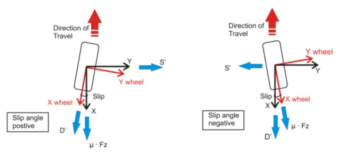
Tyre axis system . . . 36
Slip angle . . . 37
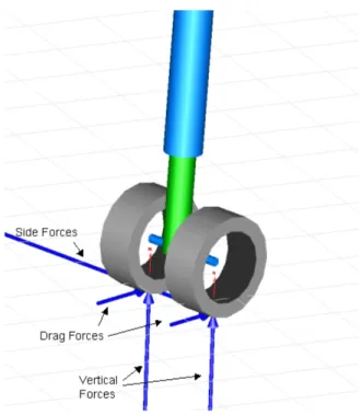
Side and drag forces . . . 41
Vertical forces . . . 44 Model description . . . 48 2.4.2 Shock absorbers . . . 51 2.4.3 Hydraulic components . . . 55 2.5 Summary . . . 58 3 Description of Models 59 3.1 Introduction . . . 59
3.2 Ground dynamic equations . . . 59
3.3 Aircraft mechanical model . . . 62
3.3.1 Landing gear assembly . . . 62
3.3.2 Model description . . . 62
3.4 Hydro-mechanical model . . . 66
3.4.1 Steering system . . . 66
Nose Wheel Steering . . . 66
Body Wheel Steering . . . 67
3.4.2 Actuators implementation . . . 70
3.4.3 Model development . . . 72
3.5 Full Aircraft model . . . 76
4 Tests Conducted, Results and Discussion 78
4.1 Introduction . . . 78
4.2 Components tests . . . 79
4.2.1 Wheel tests . . . 79
4.2.2 Landing gear tests . . . 84
4.3 Turning manoeuvres . . . 86
4.3.1 Check of model robustness . . . 87
4.3.2 Aircraft moving in a circle . . . 89
4.4 Hydraulic model tests . . . 93
4.4.1 Servovalve close loop test . . . 95
4.4.2 Failure of the hydraulic system . . . 96
4.5 Design of experiment . . . 102
4.6 Improving simulation time . . . 106
5 Conclusion and Future Work 108 5.1 Thesis overview . . . 108
5.2 Future work . . . 109
Mechanical and Hydraulic models . . . 109
CATIA link . . . 109
Updating models data . . . 110
5.3 Conclusions . . . 110
5.3.1 Discoveries emerged by the Environment investigation . . . 110
5.3.2 New possibilities . . . 114 5.4 Summary . . . 116 Bibliography 120 Appendices 120 A MultiBody library 121 A.1 Modelica.Mechanics.MultiBody . . . 121 A.1.1 Information . . . 121 A.1.2 Modelica.Mechanics.MultiBody.World . . . 122 Information . . . 122 A.1.3 Modelica.Mechanics.MultiBody.Forces . . . 130 Information . . . 130 Modelica.Mechanics.MultiBody.Forces.WorldForce . . . 131 A.1.4 Modelica.Mechanics.MultiBody.Sensors . . . 133 Information . . . 133 Modelica.Mechanics.MultiBody.Sensors.AbsoluteSensor . . . 134 A.1.5 Modelica.Mechanics.MultiBody.Parts . . . 142 Information . . . 142
Modelica.Mechanics.MultiBody.Parts.Body . . . 143
A.1.6 Modelica.Mechanics.MultiBody.Interface . . . 151
Information . . . 151
1 Layout of the thesis. . . vi
1.1 Relationship of processes for engineering a system (ANSI/EIA-632-1998, 1998). . . 4
1.2 Seven systems of system engineering (Martin, 2004). . . 5
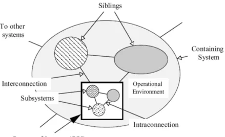
1.3 A system with its sibling systems (Hitchins, 2005). . . 7
1.4 Technical Evaluation Process. . . 9
1.5 Three-dimensional system development in a product line (Amir Tomer, 2002). . . 12
1.6 Provenance and pedigree concepts. . . 13
1.7 Object concept. . . 16
1.8 Research context. . . 22
2.1 Logical grouping of containers. . . 25
2.2 Connection between wheels and shock absorber. . . 36
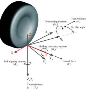
2.3 Tyre axis system defined by the SAE and the one utilized. . . 37
2.4 Definition of the slip angle α and the steering angle δ. . . 38
2.5 Understeer and oversteer of a vehicle. . . 38
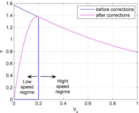
2.6 Transition between low to high speed regime in the slip calculation. . . . 41
2.7 Wheel deformation during a turning manoeuvre. . . 41
2.8 Drag force coefficients for the nose landing gear. . . 42
2.9 Side force coefficients for the nose landing gear. . . 43
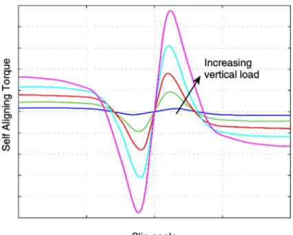
2.10 Self aligning torque coefficients for the nose landing gear. . . 43
2.11 Forces acting on the wheel. . . 44
2.12 Block calculating lateral forces acting on the wheel. . . 45
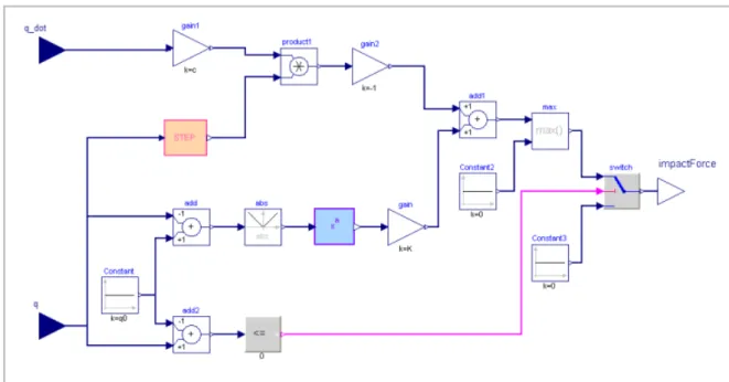
2.13 Tyre-ground interface force implementation. . . 48
2.14 Smooth step function utilized. . . 48
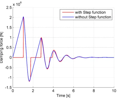
2.15 Compression-only Damping Force calculated with and without step func-tion. . . 49
2.16 Compression-only Spring Force. . . 49
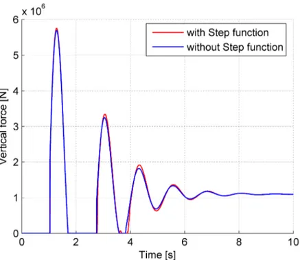
2.17 Impact function using or not a step for the damping force. . . 50
2.18 Scheme of the tyre implementation. . . 51
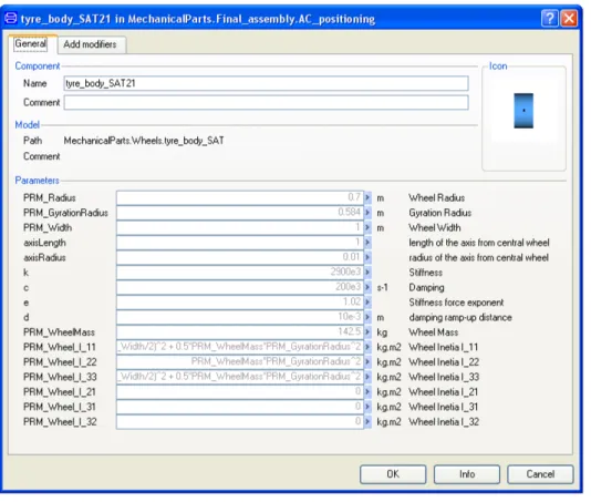
2.20 Tyre parameters the user is allowed to choose. . . 53
2.21 Stiffness force. . . 53
2.22 Compression and rebound parts of damping force. . . 54
2.23 Stiffness and damping block. . . 55
2.24 Shock absorbers model. . . 56
2.25 Swivel valve schematic representation. . . 56
2.26 Swivel valve modellization. . . 57
2.27 Steering selector valve in the Body Wheel Steering . . . 57
2.28 Steering selector valve modelling. . . 58
3.1 Bicycle model. . . 61
3.2 Mechanical model of the aircraft. . . 63
3.3 Parameters of a body landing gear bogie. . . 64
3.4 Position of the revolute joint. . . 64
3.5 Principles of the nose wheel steering control. . . 67
3.6 Kinematics of the NWS actuators. . . 68
3.7 Principles of the body wheel steering control. . . 69
3.8 Body Wheel Steering position law. . . 69
3.9 Diagram of cylinder model composed of system-elements parts. . . 70
3.10 Ideal cylinder. . . 71
3.11 Nose Wheel Steering blocks subdivision. . . 72
3.12 Nose Wheel Steering system overview. . . 73
3.13 Body Wheel Steering system overview. . . 75
3.14 Hydraulics-Mechanics link. . . 76
3.15 Three dimensional animation of the NWS including steering mechanism. 77 4.1 Three dimensional animation of the wheel component. . . 80
4.2 Trajectory followed by the wheel. . . 80
4.3 Vertical force obtained changing its characteristic parameters. . . 82
4.4 Results tyre component tests. . . 83
4.5 Vertical forces, landing gear test. . . 84
4.6 Stiffness and damping forces in the shock absorbers. . . 85
4.7 Side and Drag forces. . . 86
4.8 Slip comparison at 15 knots. . . 88
4.9 Slip comparison at 30 knots. . . 88
4.10 Trajectory comparison 15 knots. . . 89
4.11 Slip angle comparison at different velocity. . . 89
4.12 Steering angle input. . . 90
4.13 Trajectory followed by the aircraft. . . 90
4.14 Explanation of the instability generation. . . 91
4.16 Three dimensional visualization of the rotating flange with the two
push-pull actuators. . . 93
4.17 Servovalve command and steering angle for the change over test. . . 94
4.18 Change over point of the rotating flange. . . 95
4.19 Pressure in the left and right actuators, focusing on the change over point. 96 4.20 Desired and achieved angle of rotation of nose landing gear. . . 97
4.21 Servovalve input current achieved from the simulation and flight tests. . 97
4.22 Actuators pressure. . . 99
4.23 Normal selector valve command and steering angle for the free to castor test. . . 100
4.24 Actuator pressure in the free to castor test. . . 101
4.25 Opening command of the bypass valves. . . 102
4.26 Trajectory changing the z coordinates of central of gravity. . . 103
4.27 Trajectory changing the x coordinates of central of gravity. . . 103
4.28 Vertical load changing the x coordinates of central of gravity. . . 104
4.29 Nose wheel tyre slip angle changing the x coordinates of central of gravity.105 4.30 Steering angle changing pressure supply line. . . 105
4.31 Pressure changing pressure supply line. . . 106
4.32 Changing in the CPU time selecting the appropriate states of the model. 107 5.1 Dymola block imported into Simulink. . . 115 5.2 Computational design methods operating on a system simulation model. 116
Research Context
1.1
Introduction
In this chapter the author outlines the research context in which this study was con-ducted in Airbus. In section 1.2 the Airbus mission is given. The author has interpreted the Airbus mission in order to define the needs and the direction of this research as a potential contribution to this mission.
For the reader to understand the research context, an overview on system engineering is given (section 1.4). Recognizing that aircraft systems have become progressively more mechatronic in nature, the systems engineering context in relationship to mechatronic system is given. Model Based Engineering is also described as a paradigm for support-ing systems engineersupport-ing. In particular, the research interests are focused on the area of Modelling and Simulation. The rationale for reusability of models is also explored (section 1.5.3).
This chapter concludes by defining the project aims and objectives, thereby setting the research context.
1.2
Airbus mission
Airbus is the world’s major aircraft manufactures and designer of civilian aircraft, and it consistently captures half or more of the market sectors.
“Airbus’ mission is to meet the needs of airlines and operators by producing the most modern and comprehensive aircraft family on the market, complemented by the highest
standard of product support”1.
Airbus continually looks to introduce modern technologies, methods, means and pro-cesses, to ensure that it meets and anticipates the evolving needs of its customers. The goal of this thesis is to contribute to the “methods” and “means” axis.
1.3
Mechatronic systems
Over the last three decades civil aircraft systems have become progressively more inte-grated between structure, power, control and software. This requires different disciplines to fully express the functionality of the system under design. As the system-elements are tightly coupled, hence their mechatronics nature, so the different disciplines needed to design the system have become tightly coupled.
The traditional design approach for multidisciplinary systems was a sequential ap-proach, first building the mechanical system, then sensors and actuators and finally the control system. The control systems were implemented as analog computers, however, also over last three decades, there has been a transition to digital computer systems and now to Integrated Modular Avionics. In the design of mechatronics, the desired synergy between the different domains can be achieved if all different disciplines are designed together (Rajarishi Sinha, 2000).
Traditionally, during the design of mechatronic systems the primary interaction between elements tended to be lumped, i.e. the assumption was that a system can be developed as sum of different subparts connected together (the cartesian view). However, in recent times, there have been observations that have challenged this view.
When subparts are connected together, they often exhibit properties, capabilities and behaviours that the parts, individually, did not exhibit. Joining parts together affects the parts themselves, in the sense that each part does not operate and behave in iso-lation, but acts and reacts with interfacing parts, thereby contributing to the overall properties, capabilities and behaviours of the system. It is also recognised that the de-sign of these system-elements, and therefore their representation as models, was also conducted in a discrete way. However, this aspect was often negated because the analy-ses were conducted with the system-elements logically connected to represent the inner structure of the system. When system-elements are connected together earlier in the design phase, the design engineer is more likely to discover undesired and unintended functional coupling, and their unintended nonlinearities. Early in the design phase,
changes can be made easily and cheaply, thereby allowing the design engineers to take the appropriate actions of mitigating these undesirable discoveries. To produce the desired external effects it is necessary to have synergy, cooperation and coordination between the parts, i.e. emergence. By emergence it is meant the tendency for “high-level” properties to magically appear from a collections of “low-“high-level”, where the analy-ses of the low-level properties, individually, would not have indicated such properties, (Damper, 2000).
1.4
System engineering
1.4.1 Overview
In this section Systems Engineering is introduced with a view of showing its importance in ensuring that the right product is built and deployed. Systems Engineering should not be confused with Systems Design Engineering as they have different roles and different focus. Whilst this thesis is not about Systems Engineering, a short definition may help to clarify the roles and foci of these disciplines, and describe the interrelationships between Systems Engineering, Model-Based Engineering and System Design Engineering. Systems Engineering is an interdisciplinary approach and practice to enable the realiza-tion of successful systems (ANSI/EIA-632-1998, 1998).This approach aims to integrate the disciplines and specialty groups into a team effort, forming a structured development process, that proceeds from concept to production, to operation, to sustainment, and eventually, to disposal. Systems Engineering considers both the business and the tech-nical needs of all customers with the goal of providing a quality product; a product that meets the user needs. In the early phases of a project, the System Engineer frames and categorizes the needs thereby defining the properties, capabilities and behaviours (char-acteristics) that potential solutions should exhibit. Additionally, the System Engineer defines the “values” that the potential solutions should provide, thus enabling selection of optimal solutions from a set of candidate solutions. During the later stages of a project (ANSI/EIA-632-1998, 1998),the System Engineer manages the deployment and subsequent assessment of the product in its operating environment. The role, therefore, is throughout the whole lifecycle of the product, including the disposal of the product at the end of its life.
System Design Engineering, on the other hand, is the set of activities undertaken to apply engineering knowledge to convert the requirements into product parts, such that the product parts, when assembled, satisfy the requirements of the acquirer and other stakeholder. In figure 1.1, this is the process labeled System Design, consists of two top level processes; viz. Requirements Definition Process and Solution Definition Process.
This is the traditional, and well-known, domain of the system design engineer.
Figure 1.1: Relationship of processes for engineering a system (ANSI/EIA-632-1998, 1998).
The role of the systems engineer was further explored and clarified by Martin during the International Symposium of INCOSE 2004 (Martin, 2004). He stated that there are seven interrelated systems (see figure 1.2) that must be considered to ensure that the right product is designed and deployed.
The system in which the need arises is the Context System (S1). In this thesis, S1, is the Air Transportation System before a new product is introduced. A new product is intended to transform the Context System into the Modified Context System, S1’, Air Transportation System after the new product has been introduced. In doing so, the new context may have new, undiscovered needs, and predictions may need to be made to determine the most likely future scenarios.
The Realisation System (S3) is the System of People (airframe manufacturing organisa-tion) that aims to make the transformation. In order to ensure that the transformation
Figure 1.2: Seven systems of system engineering (Martin, 2004).
is the right one, S3 needs to understand both the “as is” context (S1), and the “to be” context (S1’). Once the needs are understood, the Realisation System will engineer an Intervention System (S2), such that a project team is set up to design, develop, test, accredit and deploy the new product, and the associated system-elements, as the Deployed System (S4).
In order for the Deployed System to fit into its operating environment, its relationship between existing systems may need to be modified. The modified systems “collaborate” with the Deployed System, and hence is referred to as a Collaborating System (e.g. passenger embarkation and disembarkation systems). To ensure continued service of the Deployed System, a Sustainment System (S6) may need to be developed, if one does not exist (e.g. supply of fuel to the aircraft).
In the mean time, there may be another system that competes with the Deployed System. The organisation (S3) therefore needs to ensure that the viability and value of its product is greater than that offered by the Competing System (S4). An example of a Competing System may be a Rail Transport System.
The typical life-cycle is shown in the above figure. The relationship of modelling and simulation in this context can now be explored.
1.5
Model-Based Engineering
If the role of System Engineering is to understand and frame the problem, then the role of Modelling is to help represent that understanding, and the role of Simulation is to appraise that understanding. Simulation is used by both the Realisation System (S3) and the Intervention System (S2) to predict the characteristics that their evolving product will have (or need to have) in potential Modified Context Systems (many S1’). Since there are multiple perspectives, which change over time, there needs to be many models and many simulation platforms reflecting these evolving perspectives.
From the product design viewpoint, these models represent the different facets that designers may want to explore and understand. By using appropriate simulation tool, these models can be used to build virtual prototypes and early tests conducted to ensure that the product design is progressing as intended. These simulation environments also allow the design engineers to make predictions about the way that the system will behave in its future operating environment.
In order to specify the system features, and predict its operating characteristics, it is important to understand the context in which the system will be used 1.3. This means that the designers must respect the interfaces that the system will needs to have, for interacting with its sibling systems, and the environment in which it will “reside”; the system also interacts with its environment. Whilst the focus of the designers may be in the system under design, they must ensure that the interfaces are properly understood and managed.
The Simulation Models are product that needs to be engineered, therefore the approach shown in figure 1.1 is also applied to the development of the models. The Simulation Models will consist of interacting sub-models, sub-parts, etc.
Model Based Engineering is an approach that allows improvements in the quality and maturity of the final product through the use of models and simulations. The models are used to represent the design in an unambiguous way, while the simulations allow experimentation to be conducted to determine system parameters and predict system performances. More importantly, Model Based Engineering is a flexible process, that has the ability to react to rapid changes of requirements and quickly produce new scenarios.
Figure 1.3: A system with its sibling systems (Hitchins, 2005).
1.5.1 Safe engineering practice
The term safe engineering practices has been applied to the process and procedures that engineers should follow, to reduce the likelihood of error propagation. As a loose definition, Safe Engineering Practices are processes that are followed to ensure that:
• the task to be undertaken is the right task (validation against the project needs), • the information needed to conduct the task is available (validation against the
product definition),
• the task is conducted in a specified manner (validation against the corporate standards),
• the specified manner has error detection and correction built into the task, • the task outcome are reviewed, checked and approved, (verification against the
project needs and product definition) and
• a continual improvement process is followed.
These practices aim to protect the project, product and the people who operate the process.
For example, in the manufacturing environment, safe engineering practices are ways of working that minimise the danger to the operators, as well as ensure that the product is
built correctly. Further, it extends to the tools being available and maintained to a good standard, the operator being properly trained in using the tools, and the appropriate constrains in place to contain possible stray energy sources. These are all aspects of validating that the task is ready to be undertaken. At the end of the task, a verification process ensures that the manufactured article is in accordance with the specification of the article (material, dimensions, surface finish, tolerances, etc).
Extending this idea to modelling and simulation, safe engineering practices is the ap-proach to creating models such that the right model is built, and that its scope of use are understood, and the model interfaces are well defined. This implies that the modeller is trained to use the tools and ensures that the scope of use is well established (Peter Fritzson, 2004). Again, the aim being to reduce the likelihood of building the wrong model, or misusing a model.
One aspect of this approach can be achieved by following the process described in figure 1.4. For example, ensuring that the model is consistent with the intent of the system specification, and tracing the model elements back to the specification.
Another aspect is related to the way that the models are developed. In physical systems, it is well known that one domain cannot be connected to another domain without an actuator or a transducer. However, certain modelling languages allow these connections to be made without conducting a domain check, nor indicating an error. Using a lan-guage that is able to understand the different physical domain, and stop non-physical connections being made, will help to support the safe engineering practices.
1.5.2 Model Validation and Verification
A way to increase the safe practice is to prepare a well defined system architecture, components and interfaces. It is also necessary to be capable of verifying the design properties against both the informal and formal requirements, especially for complex systems. This enables to guarantee that the model we have is fit for purpose and is ready for use in generating information such that design decision can be made.
Before using the model for further investigations, the initial task is to validate and verify the model on the basis of the available experimental results. In the Technical Evaluation Process, four processes are involved: System Analysis, Requirement Vali-dation, System Verification and End Products Validations. The next figure shows the relationship between these processes by ANSI/EIA Standards (ANSI/EIA-632-1998, 1998).
Figure 1.4: Technical Evaluation Process.
The dictionary 2 definition of Validate is “to support or corroborate on a sound or authoritative basis”. In the context of this report, Model Validation may be elaborated as documented answers to the questions,
• What are the source of the equations?
Equations would have been derived from either an existing “body of knowl-edge”, or through research activities aiming to build upon a body of knowledge.
“Body of Knowledge” is peer and expert reviewed, therefore forms the pre-vailing paradigm.
The applicability of the equations for the intended purposes needs to be demonstrated, as does the scope of use and potential limitations.
• How will they be solved/simulated?
The way that the equations will be solved leads to the development of algo-rithms, which will also need to be documented, and its relevancy to the solution shown.
The method of solution guides the selection of simulation tools that may be used.
The constraints and limitations of the methods needs to be documented. • What tool will be used to solve/simulate them?
Finally, the choice of tool to conduct the simulation/solution needs to be made.
The applicability of the tool needs to be demonstrated and documented.
Similarly, the dictionary definition (ibid.) of Verify is “to establish the truth, accuracy, or reality of”. Again, in the context of this report, Model Verification is the documenta-tion of evidence that the models, when executed in a chosen simuladocumenta-tion environment, for given scenario, and parameter set, produce simulation results that demonstrate the sim-ulation’s capability to represent known reality. By simulation we verify the equations, solution methods, scenario and model parameters.
By conduction validation and verification on the models, the successful outcome is effec-tively the statement that the models, and the associated simulations, are ready for use in validating and verifying the system requirements and design solution, respectively.3 There are two main techniques of verification utilized to verify complex systems.
Static verification
Static verification is an automatic technique that focuses on the check of the consistency of a model before it is executed. In this verification static checks of type constrains, unit checking and physical domains checking are included. Furthermore it is fundamental the check of models against the requirements. This indicates guarantee to be expressed against the model, that the model exhibits the properties express by the requirements.
3The ideas of Model Validation and Model Verification for Physical Systems, given here, were
Dynamic verification
Dynamic verification includes a wide range of verification techniques. It consists in systematic tests to conduct in many possible combination of the design parameters. In this way instead of having only one numerical value for a parameter it is possible to have a distribution of variables with a certain probability.
The dynamic verification allows to run a model for distribution of values for design parameters. In this way, hopefully, the design space of the implemented system, will result completely described, resulting in a more close to reality design.
1.5.3 Engineering Reengineering Reuse of Models
According to Tomer and Schach (Amir Tomer, 2002) there are three directions of system development activities:
• Engineering (analysis and design) • Reengineering
• Reuse
The entire life cycle of the design of a system can be described in a three-dimensional space with these activities on the axis. The horizontal axis is labeled “engineering”, a term that indicates the course of engineering process. The direction of this axis is towards “progress”, as the engineering process continues, the design progresses.
The second axis “reengineering”, is necessary because the design can change during the development as the requirements can change. In this case feedback loops are followed during the development of a system. According to IEEE 1220 reengineering is defined as “the process of improving a system after production through modification to correct a design deficiency or to make an incremental improvement”. The positive direction of the reengineering axis is indicated as “effort”, to describe the work necessary to redefine a system.
When a new system shall be developed, it is quicker to reuse existing models, instead of developing all its parts from scratch.
The third axis of figure 1.5 represents the life cycle of a system design, is labeled Reuse. Reusing components is becoming more important in every company in order to shorten
the development of new products. This is one of the major reasons for developing components organised in a library.
Figure 1.5: Three-dimensional system development in a product line (Amir Tomer, 2002).
In Chapter five it is described how the mechanical models developed can be parameter-ized in order to be able to change their characteristics. It is also shown how, choosing a sufficient number of parameters, a submodel or a part can be generalized and reused in other models.
Model traceability
A system evolves along the evolution axis: from a feasibility study to a concept, a design phase and finally a manufacturing phase in which the product is eventually assembled. Then there are the “on service” phases and so on. These phases are represented on x-axis in figure 1.6. These same phases are also followed when a new version of the system is necessary. When passing from a version to another one we are moving along the y- changing axis.
When developing new models, the “agility” in changing from one model to another one and in characterizing their properties, as will be outlined in section 1.8.1, is fundamen-tal. Reuse is a key contributor to agility when developing models. There are two types of model reuse (Amir Tomer, 2002):
Figure 1.6: Provenance and pedigree concepts.
• Glass-box reuse: the model is modified, as an example the structure is changed before utilized in a new system.
When reusing a component, as shown in figure 1.6, the designer faces two different alternatives: to utilize the component as a black box, or as a glass box. When reusing a model as a black-box the concept of “provenance” is fundamental, while when the component is reutilized as a glass box, it is important to record all the models changes, hence the concept of “pedigree” (Sanjiv Sharma, 2007). In the figure it is also possible to see that the reusability direction of growing goes in the opposite direction of model evolution. The more a model is completed, detailed and specific the less is reusable. While the more a model is basic, more likely it can be reused in other design process. For this reason, as it is possible to see also in figure 1.5, it is fundamental to keep trace of the models evolution.
Reusing black-box components is usually too restrictive, because it represses technologi-cal development. Hence it is necessary to extract design information at a sub-component level in order to allow innovation.
It is essential to develop the ability of modifying components as wished that can be reintegrated into a new architecture. For this reason it is fundamental to have trace of modelling activities over the overall life cycle and the evolution of the system. In this way, the process of designing a new system will results accelerated due to the possible reuse of the existing library components.
To summarize in order to be able to reuse components it is necessary to know
• their provenance • their pedigree
• and have designed and managed libraries.
With the word “Provenance” are meant: the needs the model addressed, if it really met them, how the model was produced and tested, by whom, and when. The word “Pedigree” instead is referred to the evolution the model followed: which are the mod-ifications made on the model, by whom did they were made and why, what are their scope of use.4
The “Designed and Managed” libraries are libraries of reusable well tested components, complete with their documentation (provenance and Pedigree) organized in a systematic way.
1.6
Modelling and simulation
1.6.1 Definition
The interest in Modelling and Simulation for engineering applications has growth sig-nificantly in the recent years.
The role of modelling and simulation in industrial product design and development is fundamental. Design mathematical models representing a system in the computer is a method utilized for reducing costs, determining and optimizing the system properties before it will effectively built. This way of design can easily reduce development time and increase the quality of a system.
“An experiment is the process of extracting information from a system by exercising its inputs” (Fritzson, 2004). With the aid of computers we can build models of the system, interrogate them, and produce experiments using them, this is called Simulation. If the model is representative, results can be produced from it as many times as required. Using validated models, the need for a large number of physical experiments on test equipment can be avoided; instead experimentation through models can be used. The fundamental reason for modelling is then to have a representation of the system to be
4The ideas of “Provenance” and “Pedigree”, given here, were developed through dialogue with Sanjiv
designed. This can then be used to investigate the system behaviour in situations that are not possible to test in reality because the number of tests is too large or because the model produces results quicker than physical tests.
Modelling and Simulation is a mean that allow to apply a more holistic viewpoint that the System Engineering process aims to promote (Coetzee, 2005b). Furthermore it is a mean to obtain optimum systems integration, and a product that satisfies the needs of the customer.
1.7
Types of modelling languages
“A modelling language is any artificial language that can be used to express information or knowledge or systems in a structure that is defined by a consistent set of rules. The rules are used for interpretation of the meaning of components in the structure”5. Modelling languages can be textual or graphical.
Script languages
Script programming languages allow to model a system focusing on the implemen-tation of the code. These languages use standard words together with parameters to make computer-interpretable expressions, as an example to implement the equations representing the dynamic behaviour of a system.
The user needs to rearrange equations to suit a particular problem, i.e. inputs and outputs are fixed, there is no acausal flow of equations, see article 1.7.
Although the writing and rearranging of equations is a task that often requires time and effort by the developer, there are the advantages of remain in contact with the mathematical description of a system, of knowing which are the assumptions made and so their consequences.
Graphical languages
Graphical modelling languages use a diagram techniques, employing symbols that rep-resent concepts and lines that connect the symbols and reprep-resent their relationships. These kind of languages are widely used in modelling avionic system in the aerospace
industry as they are well suited to represent signals. Typical models utilized in graphical languages are input-output blocks.
Object-oriented languages
To handle description of large systems is today much more often used object-orientation, a concept that helps the structuring approach to modell a system.
According to Parpola “the object-oriented approach is a paradigm distributing repre-sentation over a number of active entities, called objects”.
Using the object-oriented approach the important parts of a system can be identified as “objects”. An object is a counterpart for a real world concept. The concept selected to be modelled as object classes can be concrete or abstract, depending on system requirements. In figure 1.7 is outlined the concept of an “object”.
Figure 1.7: Object concept.
Thinking in object-orientation terms helps the developer because he can thinks in term of real “objects”, and can link models together as they are in real world. Instead using classing programming languages it is not possible to think in term of physical objects, but it is necessary to write the equations that represent the physical system, often large non linear differential system of equations.
Furthermore, as an example, today is possible to have three dimensional animation, that helps engineers to understand first the geometry and then the behaviour of the system they are going to design, through the visualization of it.
Models are built from object type (or classes). From a class definition is it possible to create objects that are known as instance of the class. The class is essentially the plan
of how to design the object. A class contains:
• Variable declaration: the data about the object • Equation sections: specify the object functioning
The possibility of extending the behavior and the properties of an existing class is one of the major benefits of object-orientation. The behaviour and properties of a class in the form of equations and content are re-used or inherited by other subclasses. In this way the resultant code will be more compact, without the need of rewriting many similar pieces of code.
In encapsulating the way that the model-element behave as an object, means that it is self contained. The changes made to an object effect only that object, and not other objects that it interfaces to, section 1.7.
For creating object representing a system of different level of granularity it is possible to use already existing objects, drag and drop them into another object.
Equation based languages and acausality
Most of the modelling and programming languages use the following form of equations:
variable = expression
The equations have to be rearranged in this form by the developer, then the value of each variable declared are calculated following the procedural order: first is calculate the earliest variable, then the second and so on. This way of proceeding forces the developer to rearrange manually the equations to suit a particular problem. As consequence a model developed for a certain purpose, can with difficulty be reused for a different task, as in this case the “known variables” can became the unknown, so the inputs and outputs sweep each other.
The term “causality” is referred to the flow of equations, if this flow is fixed, the inputs and outputs are defined. Instead, if the flow of equations is not fixed, than a model is acausal, meaning that the direction of the variable flow is not fixed and can go in each direction.
Consequently, utilizing a classical acausal model, multi versions of components model must be developed to suit every causality. This will also require a large amount of
maintenance and effort for debugging models.
In acausal languages the relationship between all the variables in a component is de-scribed by equations: The form utilized is
expression = expression
Equations are more flexible than assignments because they do not prescribe a certain flow direction of equations or order of execution. There is no need to rearrange equations to suit a particular problem, instead the component develop can be used in every model without defining which are the inputs and the outputs.
For example consider a resistor equation:
V = R · i
where V is the voltage, R is the resistance and i the current. This equation can be used in three different modes that corresponds to three different assignment statements:
i := v/R v := R · i R := v/i
In these assignment statements, variables on the left hand side are always outputs, while variables on the right hand side are inputs. Instead equations do not specify which are inputs and which are outputs. In this case the equation utilized is simply V = R · i, i.e. the causality is not specified and become fixed only when the equations related a particular problem are solved. This is called acausal modelling, and it is very well suit for representing physical systems.
Another meaningful example to show the power of acausality is an hydraulic component: when modelling a valve in usual languages, it is necessary to establish which are the known and unknown variables. In the valve case it is necessary to fix either the flow rate or the pressure at its ports. This is an abstraction the user is forced to make to represent an object that in reality does not have instances like pressure and flow rate as inputs or outputs, but these are values that can be measured at its ports.
One of the key advantage utilizing an acausal modelling language is that the solution flow of equations will adapt to the data flow context of the problem we want to solve.
Solving a particular problem the variables needed as outputs and as external inputs are defined to resolve the system of equations.
1.8
Project aims
1.8.1 Prerequisites
The use of modelling and simulation techniques, early in the design phase, enables changes to be made rapidly and the impact to the design assessed whilst making changes are still easy to do, (Coetzee, 2005a). Simulation provides immediate feedback to the designers for design decisions that they take, thereby fundamentally changing the level of information available to them. The design process can became quicker and more flexible by using these techniques. However, to fully exploit the advantages of modelling and simulation techniques, the models must have appropriate levels of granularity and be easy to use. To enable this ease of use, and timely availability of these models, the process of creating the right model must also be rapid and easy to implement.
To take advantage of the capabilities provided by simulation, it is important to develop a modelling paradigm that supports model reuse (Rajarishi Sinha, 2000). The main aspect of this paradigm is to be able to integrate it with the design environment. Provision of simple and intuitive interfaces are also necessary so that models can be utilized and analyzed by domain engineers.
This project aims to introduce such a paradigm, based on model composition from well developed and documented components. Particulary the goal is applying this modelling paradigm in a multidisciplinary environment, where the focus of design is to describe the multiple facets of mechatronics systems.
In the past specific tools have been used for the design and simulation of different physical system-elements. In the aeronautical industry, MSC.Adams has been used for multi-body dynamics, three dimensional visualization of mechanical parts and dy-namical analysis, Easy5 and MSC.Adams have been used for the hydro-mechanical systems, whilst Matlab-Simulink primarily for the avionics. As indicated above, these system-elements are an integral part of any mechatronic system, therefore, the need for interoperability between these domains must be preserved for these tools.
As in other mechatronic industries, the need for tool interoperability is also as strong for aircraft systems design.
connected together, avoids complications like cosimulation.
The “Environment” for Modelling and Simulation must also reflect the evolving phases of an aircraft project where design “richness” increases6 over time.
The benefits of this approach will be that the physical system engineers will use a com-mon language to describe the plant. The interoperability will enable the system design engineers to assess the interaction between the plant, the avionics and the containing system. The interaction of mechatronic system is complex, the aim of this approach is to provide means for the system design engineer to navigate through this complexity. Furthermore the “Environment” for modelling and simulation should be capable of absorbing the entire design cycle of a system, from a preliminary to a detail design, and all the simulation phases.
The “Environment” shall also allow agility in systems development, necessary both for concepts selection and for answering the needs of rapid changes in design objectives and requirements.
As a safe “practice”, there is an increasing need of means and methods allowing checking of models, i.e. to check systems consistency before they will be interrogated.
An aspect emerged during the design of a complex systems is the importance of dividing them into submodels. Subdivision in lower level components is important first because it helps model users to understand how it structured and conceived. Subdivision also helps the debug process, as it is easier to find problems in simpler submodels.
Furthermore it is important to understand which are the right components parts sub-division utilized in a complex model because, them, in future, can be possibly reused. When a new design paradigm emerged, the developers initially examine the existing solutions. For this reason, nowadays more than ever, the needs to organise the research and development efforts have arisen in many companies. This occurs mainly through the reuse of existing components in creating new products.
When developing a new system architecture it is not desired to reuse a completely defined components, otherwise the result system will be similar to the existing ones. As an example in the landing gear case it is important to develop components like tyres, mechanical parts assembly, shock absorbers and steering system that can be reused for creating a landing gear of another aircraft. Creating an overall landing gear model, instead, it is not desired, as will not give the user necessary flexibility when
6
Richness: the level of granularity and design information is evolving as the design progresses and therefore enriching the product data.
developing a new system paradigm. For these reasons the necessity of these kind of library components has emerged.
Another aspect emerged in developing complex systems is the necessity of individual parts to be replaced by alternative components to allow the necessary agility in systems development. Also is necessary a simplified approach to permit model or parts exchanges between different users.
1.8.2 Project objectives
The aims of this work are to investigate a multidisciplinary and multi-physics modelling approach, and the benefits of applying it to aircraft systems, focusing on the properties and capabilities of the Modelica language.
The objectives of this work are:
• To investigate the claimed benefits of object-oriented technique for implementing the environment of reusable components.
• To create an “environment” in which re-usability of components is implemented. • To investigate the possibility of developing libraries of components, and the char-acteristics they need to exhibit, such that they can be reused in competing model architecture.
• To demonstrate these concepts by producing an integrated hydro-mechanical steering system and a mechanical model of the aircraft.
Developing Reusable Models
2.1
Introduction
In this chapter the characteristics that library components need to exhibit, that have emerged from developing complex models, are outlined. Modelica is introduced as a potential language for developing library of components necessary for creating complex systems. The second part of the chapter is more technical and focuses on exemplar library components, that have been developed and will be used in chapter 3 to generate aircraft models for ground manoeuvrability.
2.2
Characteristics of library components
2.2.1 Modelling methodology
When developing large models, it is undesirable to write all the equations of the models as a flat structure. Creating the model in one go can become more difficult to debug and, due to its complexity, often becomes difficult to understand. Instead it is better to divide an extensive model into sub-models, so that the separate parts can be created and tested in isolation before being connected together in a higher level model. Furthermore, for modelling large systems, grouping the model parts in the same functional manner as the system, will also help with the representation and debugging process.
A top-level system model represents the system architecture and as such, it persists for longer. The internal structure of the architecture does not normally persist until the design has been frozen. Therefore, developing the internal structure by using the
modular blocks from libraries would support the rapidly changing design during the assessment of candidate solutions.
Following this library approach, the ability to assess the system behaviour for different component characteristics by replacing them with alternative components can be real-ize. If the model is tested in one configuration, then, using this modular approach, it is easy to change the configuration and retest the model, without having to reconnect all the parts. This allows agility in assessing different solutions for their viability to meet the needs.
The models of the subparts need to be documented and intentionally design for reuse; this gives rises to the notion of reusable library components. As outlined in the section 1.5.3 model traceability, referring to the models provenance and pedigree is fundamen-tal for confidently reusing. In addition, utilizing this way of proceeding, the system description will be clearer and less ambiguous, therefore helping to verify that the system requirements and functions are captured.
2.2.2 Library components
The library components should also allow the modeller to approach the library creation in both a modular and hierarchical manner. It is the author belief that this will allow the system models to be easily constructed; this will be further explored in chapter 3. The definition of component models should include only internal characteristics; com-munication between the component model and interfacing models is only allowed via special connectors. Therefore, to be part of a library, a component model should be an object in its own rights, i.e. it should be developed so that it can be connected to mul-tiple instances, whilst respecting its physical meaning. This object-oriented approach is an essential characteristic for reusability.
2.2.3 Model granularity
Library blocks can have various levels of detail, so the user can select the appropri-ate granularity for a model. This can be managed through configurable subsystems. Configurable subsystem is a characteristic that enables an element of the model to be exchanged for a different representation, at a different level of complexity, whilst maintaining the same functionality and interfaces.
One of the characteristics, required from reusable library, is the ability for the user to drag-and-drop the configurable subsystem into a model, and select the correct features
for the specific model.
2.2.4 Library structure
In libraries, components need to be organize into logically associated models, referred to as “container”, figure 2.1. Within these containers, it should be possible to define sub-containers to encapsulate the assembly. The assembly should be made up of com-ponents. An assembly at the next higher level of system granularity can be a component. A container should include test harnesses to enable unit tests to be conducted, i.e. the ability to conduct tests on the assembly by introducing the right stimuli and checking the assembly responses. Assembly, component, container and test harness are artefact. The containers are logical grouping of objects and other containers (figure 2.1); they are virtual instances as they do not have any behaviour of their own. Whilst the other artifacts are objects because they have their own properties, capabilities and behaviours.
Figure 2.1: Logical grouping of containers.
Through the container organisation it should be possible to explore the model hierar-chy. This structuring of the libraries will assist in organising the library artefacts, and therefore helps the users to navigate the models and the libraries.
During the life cycle of a product many changes can occur in the system-elements that constitute the product. This means that model of system-elements will also change. If the system-element model is used in multiple instances and multiple models, managing the changes causes configuration management problems. In order to overcome this,
it would be beneficial to have a component stored only in one place and links made to it. Now when a system-element model is changed it can be tested, configured and controlled in one area, so that the user have the latest version.
This idea is similar to having a file and creating a shortcut to enable multiple user to refer to the same file. This process is called indirection; succinctly it is defined as a mechanism for connecting objects by storing, in one object, a reference to another object.
2.2.5 Library management
Once component models are generated and fully tested, they can be released for use as library components. The release process should include model validation, model verification, approval for use, and can then be used as building blocks for different models. Through access control a library can be made available to various teams of modellers for them to begin the modelling process. It is the author’s belief that this should make the model generation process efficient and agile.
The ability to release and archive complete libraries in a well managed way, it shall be possible to link it with general available configuration management tool (eg CVS – concurrent versioning systems).
2.3
Modelica
2.3.1 Background
The Modelica modelling language is developed in an international effort by the Modelica Association, which consist of members from both industry and academia, with the intent of establishing a standard for systems simulation. Modelica is an open source modelling language used for creating mathematical models of systems, for implementation as computer simulation where behaviour evolves as function of time, (Fritzson, 2004). Modelica is an object-oriented, equation-based programming language, that aims to provide efficient simulation of highly complex systems that would otherwise require high computational costs. It is suited for modelling multi-domain, heterogeneous, physical systems. It is particularly suited for modelling mechatronic systems, where there is close coupling between mechanical, hydraulic, electrical and control environments.
• Modelica is based on equations instead of assignment statements based. This characteristic of the Modelica language permits acausal modelling, i.e the data flow direction of equations is not specificated and the equations can be utilized in both directions.
• Modelica has a multi-domain modelling capability, there are components defined in different domains: mechanical, hydraulical, electrical etc, and all this different domains can be modelled in the same environment.
• Reusing of components of models is facilitated in Modelica by its object-oriented approach.
• Modelica’s language has pre-defined constructs for creating and connecting com-ponents. This ensures that one domain is not connected to another without con-sidering the physics of the connection.
Modelica is one of the first example of equation-based simulation languages. These kinds of languages have been designed to have an automatic generation of efficient simulation code for large complex engineering systems, on the basis of declarative specifications. These languages are developed with the objectives of facilitating
• Reuse
• Model exchange
• Development of libraries • Simulation specifications
The Modelica domain libraries have been developed in different technical areas; me-chanics, electrics, hydraulics etc. Complex simulation models can be built using existing or developed components through aggregating them from different physical domains. ‘ In Modelica, object-orientation is applied as a structural mathematical modelling ap-proach (Fritzson, 2004). This allows the modellers to develop the models such that they (the objects) have real world meaning and context.
In this language first of all a model has a declaration level, concept inspired from mathematical world. In this way it is declared what holds, instead of how. The developer does not need to re-elaborate the equations in algorithms to suit a particular problem, like in common procedural languages.
The interpretation that Modelica gives to object orientation, from the point of view object-oriented, declarative, mathematical language is summarized as follow :
• Object-orientation is view as a structuring concept, particularly focusing on the declarative structure and reuse of mathematical models. The three ways of struc-turing are hierarchies, links component-connections and inheritance.
• Models characteristics are expressed in a declarative approach using equations. • An object is a set of instance variables and equations that have certain data.
On the other hand
• Object-orientation is not seen as a dynamic message passing.
The declarative approach on object-orientation given by Modelica is at a higher level of abstraction that the usual object-oriented programming because there is not the need that the developer defines the implementation details of the system. Furthermore the code becomes more compact, easier to debug and change.
Modelica is a statically typed language, in contrast to dynamically typed language such as MathWorks Matlab. This means that variables types are declared as real, integer, boolean etc. In this way, during a simulation, a boolean variable can assume only two values: zero and one, and there is not the risk that it will acquire different values, as in dynamic tools. This declaration level helps to check the model consistency before simulations, and it is a strong start for checking techniques.
Modelica, being a strong statically typed language, offers the opportunity of utilizing formal verification techniques and also allow possibility of dynamic verification meth-ods. Formal verification is usually carried out by using model checking algorithms to demonstrate the satisfiability of certain model properties. The automatic checking of compatible connections between Modelica components belonging to different domains is, as an example, a formal verification. For instance it is impossible to connect a three dimensional model to a one dimensional model; only models belonging to the same category can be connected together, otherwise only using special connections it is pos-sible to link different domains. If an inconsistency is found than an error message will appear, and static checking can be utilized to resolve the problem.
2.3.2 Equation based and acausal language
Many recent simulation languages are declarative; in contrast to procedural language as Simulink.
In Modelica the design of models is based on equations instead of assignment state-ments, as in the input-output traditional Simulink blocks. This feature greatly increase the possibility of reusing models since causality does not need to be considered when developing a component. When constructing a model it is not necessary to define in-puts and outin-puts, instead it is possible to use simply “physical connections” (see section 2.3.2, that allow the flow of equations in both directions.
When solving a specific problem, then, the variables that must become inputs and outputs are defined to resolve the system of equations; for this reason equations are manipulated using symbolic manipulation. This characteristic is addressed in the article 3.2
Connectors description
Modelica is a “port-based” modelling language. It is possible to take advantage of the port-based approach both in the design and modelling of mechatronic systems. The interactions between submodels are defined by the connections between them. “Frames” are components widely used in Modelica. They represent physical connections between component parts, for example:
• An electrical plug • A mechanical flange
These kind of components belonging to the “connector” class define the interface and the interactions between the component models. Ports correspond to the point where components exchange energy with the environment, while interactions are defined by the connection between ports. We find this concept utilized in each Modelica library. As example they are called “Frames” in the MultiBody library, “Flange” in the one dimensional rotational library, “Ports” in the Hydraulic and “pin” in the electric library. Mathematically the connectors are composed of a certain number of variables and characterise the relation between these variables at a connection with another model. The variables defined change with the model they represent (insert one d example). Obviously a connection is allowed only between similar connector types, otherwise an error message will be displayed. This will also allow the static check of the model as described in the previous article.
The variables utilised at a connection are classified into two groups:
• Across (non-flow) variables: at a connection their value are equal. • Flow variables: at a connection their sum is zero
These equations are equivalent to Kirchoff voltage and current laws in electrical circuits. As an example the following connectors are defined in the Modelica Standard Library:
• 1D rotational connector:
– Across variable: angle of rotation – Flow variable: torque
• Electrical connector:
– Across variable: voltage – Flow variable: current • Multibody connector:
– Across variable: position r0 and orientation R
– Flow variable: force f and torque τ
MultiBody connectors are used for linking three dimensional objects. As an example, for attaching the wheel to the shock absorbers.
The connectors class only contains variable declarations, not equations, because these components only specify external interface for interactions. These interfaces define how the model can interact with other components of the system, but do not contain infor-mation on the internal behaviour of the model.
The tool’s interface allows the creation of packages where the created models can be filed according to function. Once created the models can be picked from the library window and dragged into a new model. The real physical connection between different objects is represented in the model by the connection lines of the component icons through connection ports.
Using the connector type has many advantages, first of all they help to generate the model because the developer effectively can think in terms of real components that are attached to each other. Furthermore this approach also has other advantages: if we want to run many simulations each time changing a position of one body, there is no need to change the coordinates of other components to maintain the attachment to the first body. The connector type will allow the objects to adapt and remain connected to other objects if the position is changed. In other simulation tools, such as MSC.Adams, it is necessary to redefine the new coordinates and connections between the bodies each time.