1 INTRODUCTION
In the year 2004, a strong earthquake struck the Benaco region in Northern Italy. The earthquake caused severe damage to both historical and modern constructions. Within the historical heritage about 250 churches were listed among the most severely impaired buildings.
This work is about the lesson learnt from the analysis of the damages caused by the 2004 earth-quake to some churches, and discusses the structural solutions appositely studied to repair and to reduce the structure seismic vulnerability of these buildings.
During the damage survey campaign, some recur-rent and classical collapse mechanisms were identi-fied: the overturning of the main façade and the compound walls, the out of plane deflection of the perimeter walls between the transverse arches and along the interstorey height, the wall in-plane shear failure. These mechanisms are well discussed in the literature (De Benedectis et al. 1993, Giuffrè 1993, Magenes and Calvi 1997, Lagomarsino 1998, D’Ayala and Speranza 2002, Griffith et al. 2003, Lagomarsino et al. 2004).
In some churches, where the lateral wall over-turning was inhibited either by massive buttresses alongside the nave walls, or by thick abutments, ex-cessive, unconstrained rocking of transverse arch pillars was frequently observed (Doglioni et al. 1994, Lagomarsino et al. 1999, Giuriani et al. 2007 and 2008).
Against these well known failure mechanisms pe-rimeter ties placed along the masonry walls are the
classical solution. Alternatively, steel truss works are often built on top of the roof pitches. As a draw-back however, in the case of long spanned building perimeter ties might be ineffective; whereas with the adoption of steel truss work high stresses might be concentrated in rather small zones and the effective-ness of the strengthening solution should be care-fully evaluated.
In some churches vulnerability was shown to be associated to less frequent mechanisms, which are not so well known and discussed in the literature.
In San Pietro Church (Roè Volciano, Brescia), one of the most severely damaged churches, two single leaf barrel vaults collapsed during the earth-quake because of the differential rocking of the dia-phragm arches, and because of the differential de-flection of the thin vault rings. In other churches the over-tensioning of the existing steel ties caused ei-ther their unthreading from the masonry walls, from exceeding the anchorage resistance, the tie yielding (San Lorenzo Church in Clibbio) or failure (San An-tonio Church in Roè Volciano).
Against these mechanisms, different solutions were proposed: internal perimeter ties hidden behind the nave mouldings, lightweight plywood roof box structures, and lightweight clay mortar spandrel ribs. These strengthening techniques, as well as the above mentioned collapse mechanisms are discussed in the paper.
Experiences from the Northern Italy 2004 earthquake: vulnerability
assessment and strengthening of historic churches
Ezio Giuriani
University of Brescia, Italy
Alessandra Marini
University of Brescia, ItalyABSTRACT: This work is about the lesson learnt from the analysis of the damages caused to some churches by the strong earthquake, which struck Northern Italy in the year 2004. Focus is paid to some mechanisms which are not well known in the literature: the excessive and differential rocking of neighbouring transverse arches, the differential deflection of single leaf vault rings, the tie over-tension induced by the transverse arch rocking. In the paper, the structural solutions appositely studied to repair and to reduce the structure seismic vulnerability of these buildings are presented. Among these solutions: internal perimeter ties, lightweight wooden roof box structure, lightweight spandrel ribs are illustrated.
2 SEISMIC VULNERABILITY OF CHURCHES The vulnerability of the churches is generally asso-ciated to the overturning of the main façade and the perimeter walls, as well as to the excessive uncon-strained rocking of the transverse diaphragm arches.
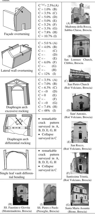
Table 1. Seismic vulnerability assessment of some churches hit by the 2004 earthquake with respect to some failure mechan-isms. Façade overturning C (*)= 2.5%(A) C = 1.0% (B) C = 3.5% (C) C = 5.0% (D) C = 5.0% (E) C = 5.2% (F) C = 3.3% (G) C = 7.8% (H) C = 10.7% (I) (A)
Madonna della Rocca, Sabbio Chiese, Brescia.
(B)
San Lorenzo Church, Clibbio, Brescia.
(C)
San Pietro Church (Roè Volciano, Brescia)
(D)
Sant’Antonio, (Roè Volciano, Brescia)
(E)
San Rocco, (Roè Volciano, Brescia)
(F)
Santissima Trinità, (Roè Volciano, Brescia)
(G)
Santa Maria Assunta (Bione, Brescia)
Lateral wall overturning
C = 5.0 % (A) C = 4.0% (B) C = - (C) C = - (D) C = - (E) C = 6.0% (F) C = - (G) C = - (H) C = 12% (I) Diaphragm arch excessive rocking C = 3.5% (A) C = 7.0% (B) C = 6.3% (C) C = <0 (D) C = 0 (E) C = - (F) C = <0 (G) C = 7.4% (H) C = 48% (I) Diaphragm arch differential rocking • remarkable crack pattern surveyed in A, B, D, E, G, H • Collapse surveyed in C
Single leaf vault differen-tial bending • remarkable crack pattern surveyed in A, B, D, E, G, H • Collapse surveyed in C (H) SS. Faustino e Giovita (Montemaderno, Brescia) (I) SS. Pietro e Paolo (Preseglie, Brescia) ( *) FS = C WTOT
where: FS is the seismic force triggering the mechanism; C is the
load collapse multiplier (also regarded as vulnerability index); WTOT
is the structure total weight.
In the churches surveyed following the 2004 earthquake, other mechanisms, such as the excessive and differential rocking of the neighbouring dia-phragm arches and the differential deflection of the thin vaults, were acknowledged as further causes of the severe damages observed.
The seismic vulnerability of the churches was as-sessed by reference to the limit analysis approach.
Table 1 shows the vulnerability coefficients esti-mated for some significant case studies.
2.1 Overturning of the main façade
Overturning of the main façade was often observed during the survey campaign (Figure 1, Table 1). This collapse mechanism was caused by the seismic action of the wall and by the possible lateral seismic thrust of the roof beams. Provided that wooden roofs are usually unconstrained against lateral movements, the latter contribution to the toppling action was quite relevant in most of the analyzed churches.
The onset of the overturning mechanism is under-lined by the development of cracks extending at the wall edges and progressively reducing their width from the top to the footing of the building. The cracks can be vertical or angled, depending of the degree of anchorage to the perimeter walls. Howev-er, it is worth noting that, the measured crack angle was always very small, thus the stabilizing contribu-tion of the lateral walls was almost negligible in most cases.
Figure 1. Overturning of the façade induced by the roof seis-mic thrust.
2.2 Excessive rocking of the diaphragm and
triumphal arches and existing tie over-tension
Excessive, unconstrained rocking of the dia-phragm and triumphal arches was recognised as an-other source of vulnerability of many churches in the Benaco area (Table 1).
In rest condition, when only vertical loads are ap-plied to the structure, the arch lateral thrust can be either largely or even entirely resisted by the but-tress action developed by the abutments, depending
on their shape and massiveness (Figure 2a, Giuriani and Gubana 1993 and 1995). As a result the possible ties are required to confine the arch thrust portion, which exceeds the buttress action. The proportion of the confining contribution mainly depends on the structure geometry and tie pretension. Conversely, in the case of rocking, the resisting mechanism sig-nificantly modifies (Figure 2b, Giuriani et al. 2007 and 2008). The crack pattern is characterized by two large horizontal cracks developing at the abutment bases and two cracks opening at the diaphragm arch springing (Figures 2b, 3 and 4). The location of the cracks depends on both the structure geometry and the local resistance.
a)
b)
Figure 2. Transverse arch resisting mechanisms under a) ver-tical loads (rest condition) and b) horizontal loads (case of full rocking, Giuriani et al. 2008).
The abutment buttress action dramatically dimin-ishes as the crack penetration progresses. In the case of full rocking, when the crack pattern is fully de-veloped, no abutment buttress action can be ac-counted for, because the resisting ideal struts be-come parallel to each other. As a result, the arch thrust has to be entirely confined by the existing ties.
Furthermore, following the cracking triggered by the rocking motion, the span of ideal arch signifi-cantly increases and so does the arch lateral thrust (Figure 2b). The span of the ideal arch in rocking condition can be conservatively assumed to be equal to the span of the ideal arch in rest condition (L*)
plus the thickness of the abutment (d) (Giuriani et al. 2007, 2008). For typical case studies the ratio d/L* was observed to range between 0,15 0, 2÷ , thus when shifting from rest condition to rocking the arch thrust could be 30 40%÷ larger than the thrust at rest condition.
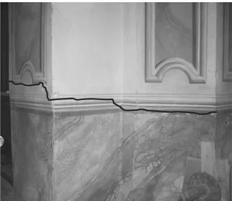
Figure 3. Madonna della Rocca Church, Sabbio Chiese, Italy. Transverse arch crack pattern induced by the seismic action.
Figure 4. Detail of the horizontal crack pattern at the trans-verse arch abutment base induced by the seismic action.
In the case of full rocking, the decrease of the abutment buttress action and the increase in the ideal arch span cause the existing tie over-tension. When the tie resistance is barely sufficient to withstand the traction force in rest condition, no extra resources are available in case of earthquake, and the collapse of the tie can be expected.
Given this foreword, the failure of the existing ties in San Antonio Church (Roè Volciano, Figure 5) was interpreted as a consequence of the onset of the transverse arch full rocking mechanism. In some
other churches, where weak existing ties were also surveyed, the over-tension caused either the tie un-threading from the masonry walls from exceeding the anchorage resistance (Madonna della Rocca church, Sabbio Chiese), or the tie yielding (San Lorenzo Church in Clibbio).
Figure 5. Detail of the welded tie rod in San Antonio Church (Manerba, Brescia, Italy). The tie rod collapsed during the 2004 earthquake.
As for the vulnerability assessment, the evalua-tion of the safety factor with respect to the onset and development of the mechanism can be obtained by reference to the traditional approach of the principle of virtual work (Abruzzese and Lanni 1999). The same approach can be also addressed to define the structure capacity curve (Housner 1963, Curti et al. 2006), to study the abutment out-of-phase rocking (Como et al. 1991), and to evaluate the tie tension (Lagomarsino et al. 2004).
A simplified method was proposed in Giuriani et al. (2007 and 2008) for the evaluation of the collapse multiplier and the tie tension in the case of either over resistant or weak ties. The seismic collapse multiplier was evaluated by introducing an ideal ad-ditional horizontal constraint at the tie level, and by enforcing that its reaction force R was nil (Figure *
2b).
2.3 Differential rocking of the diaphragm arches
and differential deflection of the thin groin vault.
The different stiffness of the transverse arches along the nave can be regarded as another source of seismic vulnerability of the churches (Table 1). The maximum top displacement experienced by the transverse arches during the rocking motion depends on the geometry and stiffness of the structure, there-fore differential displacements can be expected be-tween adjacent transverse arches (Figure 6). Notice-able differential displacement can also occur in the
case of out-of-phase rocking of neighboring diaph-ragm arches.
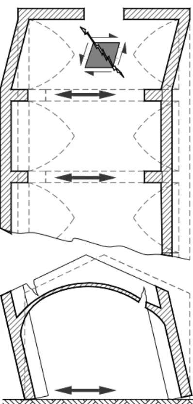
The largest differential displacements are usually experienced by the first and last bay transverse arches. As a matter of fact, the façade rarely undergo rocking, unlike the nearby transverse arch; and the triumphal arch is typically much stiffer than the neighboring transverse arch. This way, the vaults covering the first and last bays are subjected to shear distortion. When differential rocking is severe, shear distortions can be remarkable and diagonal cracks may form in the vault ring (Figure 6). The damage is more severe for thinner vaults, like the single leaf vaults. In the case of very strong earthquake diffe-rential rocking may even cause the collapse of the vault.
Figure 6. Crack pattern induced by the differential transverse arch rocking. Differential rocking, which is maximum in the first and last bay of the nave, is the result of the different stiff-ness of the transverse arches.
When subjected to earthquake loads, the nave vaults also experience differential deflection of the vault groins (Figure 7). Traditional masonry groins are connected to the perimeter walls at the imposts, whereas the vault rings are built adjacently to the pe-rimeter walls. This result in the structural disconti-nuities shown in Figure 7.
When subjected to the seismic actions Fo
illu-strated in Figure 7, groins a and b rotates counter-clockwise around points A and B. the vault groin a pushes against the perimeter wall, whereas groin b detaches from the perimeter wall and the discontinu-ity width increases for increasing seismic actions. As a result, the central portion of the vault is subjected to concentrated differential deflection. The
mechan-ism is amplified by the rocking of the diaphragm arches. contact detachement structural discontinuity vault support at the springing a B A b C D Fo Fo
Figure 7. Differential flexural mechanism of the groins of the single leaf vaults.
In the case of very strong seismic action, cracks induced by the differential deflection may extend through the vault ring thickness causing its collapse. Severe shear distortions induced by differential rocking and differential deflection of the vault were recognized as the major causes of total and partial collapse of the single leaf barrel vaults of the first and second bay of the main nave of San Pietro Church in Roè Volciano Brescia (Figure 8).
a)
b)
Figure 8. S.Pietro Church in Roè Vociano, Brescia, Italy: a) total and partial collapse of barrel vaults of the first and second bay of the main nave, and b) crack pattern induced by
the differential rocking and deflection of the single leaf groin vaults.
3 STRENGTHENING TECHNIQUES
In the following, a few anti-seismic strengthening techniques are illustrated. The presented techniques were adopted for the seismic upgrading of some churches after the 2004 earthquake.
3.1 Internal perimeter ties
The adoption of perimeter tie system is a tradi-tional technique, which was effectively adopted to secure the structure against wall overturning. His-toric constructions often present perimeter ties em-bedded within the wall thickness.
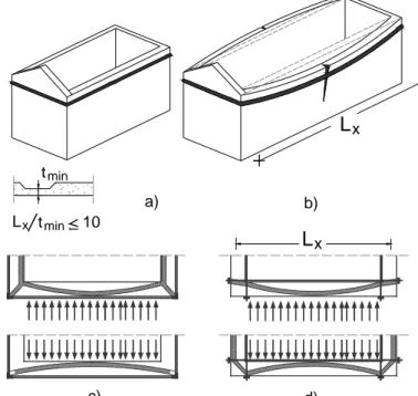
When the tie confining effect is insufficient the tie system must be strengthened or replaced. This operation is usually done by placing a new external tie system, provided that the embedment of the ties within the wall width would require expensive and difficult drilling works (Figure 9a).
Lx tmin tmin Lx 10 a) b) Lx c) d)
Figure 9. Introduction of internal or external perimeter ties.
The static scheme of the external perimeter tie system is illustrated in Figure 9c. For the solution to be effective, the perimeter ties must confine the re-sisting ideal horizontal arch, developing within the masonry wall width, at the springing. This solution was applied in San Pietro and Paolo Church, Prese-glie, Italy (Figure 10).
The same confining action can be effectively ob-tained by adopting an internal tie system, hidden on top of the nave mouldings (Figure 9d). This solution has the obvious advantage of being hidden from the sight, but it may also serve in case of irregular or preciously decorated external walls. The confine-ment of the resisting natural arch can still be ob-tained, provided that the inclined compressed strut
forms in the masonry intersections (Figure 9d). This solution was applied in San Pietro Church, Roè Vol-ciano, Italy (Figure 11).
Figure 10. San Lorenzo Church (Clibbio, Brescia, Italy): ex-ternal perimeter ties adopted as safety emergency provisional solution following the 2004 earthquake.
Figure 11. Detail of the internal perimeter ties hidden over the nave moldings in San Pietro Church, Roè Volciano, Italy.
Perimeter horizontal steel ties are inadequate in long-span buildings lacking strong transverse arches, as the wall span-to-thickness ratio is unfavourable and little constraint is provided to the toppling ma-sonry walls (Figure 9b). In this case, regardless of the positioning of the perimeter ties, the resisting arch is excessively low-raised and its resistance is negligible. In case of long spanned churches, roof box structure, which are described in the following, were alternatively adopted.
3.2 Roof box structures
As shown in the previous section, most of the ana-lysed churches were found to be vulnerable with re-spect to overturning of the perimeter walls, as well as to excessive and to differential rocking of the dia-phragm arch pillars (Table 1). In-plane shear resis-tant roof diaphragms, transforming the building into a box-structure, were adopted in these churches as a viable solution to avoid or limit these mechanisms (Giuriani and Marini 2006 and 2008).
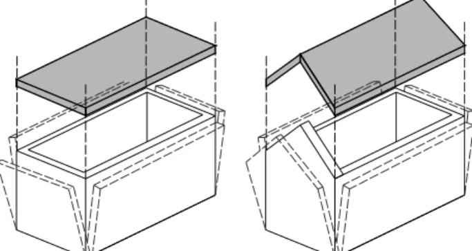
Roof box structures behave like floor diaphragms, forming a sort of lit to the underlying masonries, thus preventing the perimeter wall overturning (Fig-ure 12). The roof pitches are transformed into folded plates, which gather and transfer the horizontal seismic actions of the lateral walls, the diaphragm-arches and the roof to the shear resisting walls.
The roof box structure introduces an elastic con-straint along the roof ridge, whose stiffness depends on the horizontal flexural deformability of the roof box structure (ye, Figure 13b). The box structure
can be proportioned in order to confine the maxi-mum mid span displacement (ye) and the masonry
wall drift (β), as well as to limit the shear distortion near the supports (ye’, Figure 13b). This way the box
structure can be an effective solution to the exces-sive and differential rocking of the diaphragm arches.
The main structural elements composing the roof box structure are: the pitch-panel (1), the eaves chords (c13), the head gables (2) (Figure14).
Figure 12. Floor and roof box structure preventing perimeter walls overturning. CWc CWA CW Wc Wc FVA L h ye Fo
roof box structure ideal constraint ye ye' roof box structure W W a) b)
Figure 13. Structure behavior a) prior to and b) following the introduction of the roof box structure preventing excessive and differential transverse arch rocking.
In order to design the roof box structure of the analyzed churches, the same techniques usually adopted for the flexural strengthening of wooden floors, could have been addressed (Giuriani 2004).
Among all possible techniques, however, lighter so-lutions were preferred in order to prevent the in-crease of the dead loads, and thus of the seismic ac-tion.
The wooden lightweight box structure proposed in Giuriani and Marini (2008) were adopted. With the proposed technique roof diaphragms were ob-tained by placing overlaying plywood panels on the existing wooden roof pitches (Figure 14). Plywood panels were connected to each other by means of nailed steel flanges. The whole pitch diaphragms w nailed to the perimeter steel eaves chords, and to both roof rafters and masonry walls by means of steel studs and vertical anchored bars.
The adopted lightweight wooden box structure technique is mainly reversible and minimally im-pairing of the building integrity, and thus respectful of the modern restoration principles.
lateral walls plywood panels eaves chords head walls or triumphal arch x y z panel nailed connections facade existing planks plywood panels nailed steel straps
1
3
2
2
Figure 14. Wooden roof box structure by means of overlaying nailed plywood panels. Principal structural component and de-tail of the plywood panel assembly.
As for the structure analysis and proportioning, reference to Giuriani and Marini (2008) was made.
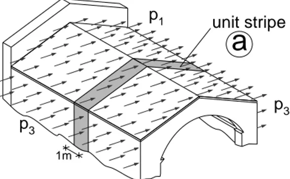
By reference to the load distribution shown in Figure 15, in order to analyze the roof box structure behavior, a two step approach was adopted. In the first step vertical and horizontal idealized additional constraints, having r1z and r1y reaction respectively,
were introduced along the roof ridge line (Figure 16). In the second step these provisional constraints were removed and their reaction forces (r1z and r1y)
were backed out.
In the first step, the unit-width stripe (a) with ad-ditional vertical and horizontal constraints, behaves
like a frame undergoing the seismic actions (case A- Figure 16). In this phase, significant uplifting vertic-al force per unit length nA may arise along the top
lateral wall. These possible tensile forces must be balanced by the wall self-weight, through anchored bars suitably embedded and distributed along the crowning masonries.
In the second step, the additional ridge constraint reactions were backed out with forces of equal in-tensity and opposite sign (f1y , f1z in Figure 16).
Pro-vided that Frame A would be a free mechanism with respect to the horizontal force f1y, for the balance to
be restored, the roof box-structure must sustain these forces (case B, Figure 16).
p1 p3 p3 1m unit stripe
a
Figure 15. Seismic action distribution
x y z r
A
: FRAMEa
1y f1y p1 p3 h Lyl
12 h3 1 y r 1z 5 4 2 1 3 = -r1y g1 nA nA r1y r1z 4 2 3 g1 g1*
*
BEHAVIORB
: BOX STRUCTUREA
: FRAME BEHAVIORB
: BOX STRUCTURE vA vAFigure 16. Structural behavior. a) Frame action and b) box-structure undergoing horizontal ridge loads.
According to Giuriani and Marini (2008), the roof box structure behavior was interpreted by reference to the classical analysis of the ribbed panels, which
( ) 3 3 12 1 y 1 3 3 A 12 * 1 y 1 3 3 1 12 1 A h p l p 2 f 2 / h p v 2 / l g L h h p h l p n + = = − + =
is based on the assumption that the in-plane bending moment and the shear force be decoupled and re-sisted by the chords and panels, respectively (Bruhn 1973). Considering a gable roof, the ribbed panels box structure is assumed to behave like a simply supported beam undergoing distributed forces f1y, in
which the eaves chords withstand the global hori-zontal bending moment, and the pitch panels resist to the shear forces induced by the horizontal load (Figure 17).
The structure proportioning was based on the re-sistance criteria, by enforcing the elastic behavior throughout the design seismic event. It is worth not-ing, however, that ductility was guaranteed at the ul-timate limit state by the ductile behavior of the nailed connections (Giuriani and Marini 2008), which are the weakest link of the structure.
n
A q1 h1 2 (y) q1 q0 hα
q0 q0 Wg dy fzW
w zw Wg fz zg fz ΔW g head gable head gable wall*
*
*
*
x y z f1y= -r1y F 13 F 13 Mmax y L x L 2 c13 c13 Ry 1 3 2Figure 17. Simplified schemes for the evaluation of the force distribution in the box structure.
The expressions of the most significant internal forces are shown in Figures 16 and 17. The eaves chord cross section was proportioned to resist the eaves chord maximum axial forces (F13); whereas
the pitch panel thickness, the panel mutual connec-tion, and the diaphragm connections to both the head gables and the eaves chords were proportioned to resist the maximum shear flow q1.
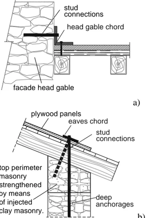
Horizontal and vertical steel stud connections were adopted to allow shear transferring to the shear resisting head gable and longitudinal walls, respec-tively (Figure 18). For the proportioning of the stud connection, mindful attention was paid to the re-duced shear resistance of the masonry wall crown caused by the lack of vertical confining load. To in-crease the stud connection resistance, strengthening
of the masonry wall crown was sometime neces-sary. To this end, injections of clay mortar along the perimeter wall crown served the purpose in most cases. Alternatively, the whole masonry crown was replaced, or a thin 20÷40 mm slab of high perfor-mance clay mortar stiffened by means of plaster meshes was cast on top of the masonry walls. Expe-rimental results proving the effectiveness of these techniques are available in the literature (Gattesco and Del Piccolo 1998; Giuriani 2004; Tengattini et al. 2006).
Distributed vertical deep anchor rebars, embed-ded along the head gable crowning masonries, were needed in some restoration works to confine the up-lift traction forces per unit length nA and fz induced
by the horizontal loadings (Figure 16). The tensile forces must be balanced by the self-weight of the “lifted masonry”. The distributed anchor bar em-bedment length was carefully proportioned for the weight of the “lifted masonry” to be sufficiently larger than the traction forces.
stud connections
head gable chord
facade head gable
a) deep eaves chord top perimeter masonry strengthened by means of injected clay masonry. plywood panels stud connections anchorages b)
Figure 18. Detail of the connection a) to the facade head gable and b) to the longitudinal walls.
Besides the structure bearing capacity, the ap-praisal of the roof structure deformability was some-time necessary. Unlike perimeter walls, which can usually endure large out-of-plane displacements with little damage, excessive in-plane shear defor-mability of the masonry vaults and unconstrained drift of the diaphragm arch pillars were shown to be responsible of serious damages and even partial col-lapses in some churches. To this end, restrictions were enforced that the roof box structure lateral def-lection y was smaller than the maximum allowable e drift of the diaphragm arch pillars; and the slope of the box structure transverse deflection at the head gable y'ewas smaller than the maximum shear de-formation γ* allowed by the vaults.
* g o z 1 1 o y 1 1 y 1 1 w tan q 2 f q cos cos q q L V cos cos 2 L 2 V q − α = = α ⎟ ⎠ ⎞ ⎜ ⎝ ⎛ α = = ⎟⎟ ⎠ ⎞ ⎜⎜ ⎝ ⎛ α α = − y 2 x y 1 y max 13 2 x y 1 max x y 1 1 y L 8 L f L M F 8 L f M 2 L f V R = = = = =
For the evaluation of the horizontal deformability of the plywood box structure, the analytical model based on the principle of virtual works proposed in Giuriani and Marini (2008) was adopted. In the model, in order to account for the nailed connection shear slip, which largely affect the global deforma-bility, reduced equivalent young and shear elastic moduli are entered.
The lightweight wooden box structure applied for the anti-seismic retrofit of the San Pietro church is shown in Figure 19.
Figure 19. General view of the anti-seismic plywood roof box structure in San Pietro Church (Roè Volciano, Bresica, Italy) and detail of the eaves chord connected to the underlying ma-sonry by means of steel studs and deep anchorages.
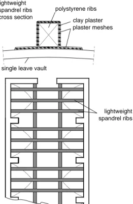
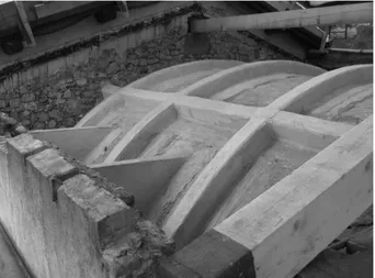
3.3 Light spandrel ribs
In San Pietro Church (Roè Volciano, Brescia), cov-ered by a single leaf masonry vault, the strengthen-ing of the structure against the differential deflection of the groin vault was necessary (Table 1).
lightweight spandrel ribs lightweight
spandrel ribs cross section
single leave vault
clay plaster plaster meshes polystyrene ribs
Figure 20. San Pietro Church (Roè Volciano, Brescia): distri-bution of the lightweight spandrel ribs along the extrados of the nave vault and detail of the spandrel rib cross section.
In masonry vaults, which are incapable to resist tensile stresses, equilibrium is guaranteed by the ideal arch developing within the vault thickness. The ideal arch corresponds to the anti-funicular of the set of applied loads. After cracking, the ideal arch must cross the solid part of each cracked sections, both at the vault key and at the springing. Single leaf vaults are usually very thin, thus the ideal resisting arch has little possibility to shift and modify within the vault thickness to adapt to different unsymmetrical load distributions. As a result, the structure is often quite vulnerable with respect to seismic load distributions, which require pronounced deviation of the ideal arch.
In order to enhance the structure resistance, spandrel masonry walls are traditionally proposed. The structure resistance is increased by increasing the thickness of the vaults, thus allowing the ideal resisting arch to adjust within the spandrel wall thickness.
In the case of single leaf thin vaults, such as in San Pietro church, attention was paid to avoid dead load increase, which in turn could result in addition-al seismic actions. Accordingly, lightweight spand-rel ribs were proposed as a new vault strengthening technique.
Spandrel ribs were designed to resist both com-pressive axial forces and bending moment. This way, the flexural stiffness of the structure was great-ly enhanced.
The lightweight spandrel ribs tubular cross tion is shown in Figure 20. The resisting cross sec-tion is made of clay mortar reinforced with plaster meshes. The inner lightweight core is made of polys-tyrene elements.
In San Pietro Church, spandrel ribs were placed along the vault extrados as shown in Figure 20. The construction phases are briefly illustrated in Figure 21.
The same technique was applied to strengthen the single leaf masonry dome covering the presbitery (Figure 22).
The efficiency of the proposed technique was al-so verified experimentally (Figure 23). The struc-ture was subjected to cyclic, unsymmetrical load conditions. Good results were obtained both in terms of stiffness and strength (Giuriani et al. 2007).
Figure 21. Light spandrel ribs construction phases: a) a layer of plaster mesh is placed overlaying the vault extrados; b) the mesh is covered with a layer of clay mortar; c) polystyrene ribs are placed along the vault ring and covered by plaster meshes; d) a thin finishing layer of clay mortar is spread over the struc-ture.
Figure 22. San Pietro Church (Roè Volciano, Brescia): light spandrel walls strengthening the single leaf masonry dome covering the presbitery.
Figure 23. Experimental test on light spandrel walls (Pisa La-boratory, University of Brescia, Italy).
4 CONCLUDING REMARKS
The analysis of the damages caused by the 2004 earthquake to some churches, as well as the struc-tural solutions proposed to reduce their structure vulnerability were discussed in the paper.
The most significant results of the study can be summarized as follows:
• In the case of full rocking, the decrease of the abutment buttress action and the increase in the ideal arch span can cause over-tension of the ex-isting ties. In the case of very weak ties, collapse of the tie can be expected. In this case, the adop-tion of a roof box structure, limiting the rocking of the transverse arches, together with the strengthening of the existing tie system might significantly reduce the structure vulnerability.
• Differential rocking of transverse arch pillars in-duces shear distortion within the vault ring, espe-cially in the first and last bay of the nave. De-pending on the magnitude of the differential rocking, large diagonal cracks may extend over the vault leading up to its collapse. In this sce-nario, the structure vulnerability can be reduced by adopting a roof box structure and by limiting the shear distortion near the supports.
• In the case of a seismic event, pronounced differ-ential deflection can be expected along the central part of thin vaults. Depending on the severity of the earthquake, differential deflection can cause the collapse of single leaf vaults. Against this failure mechanism, lightweight spandrel ribs were proposed. This solution allows to significantly enhance the stiffness and strength of the vaults.
ACKNOWLEDGEMENTS
The authors gratefully acknowledge Claudia Porteri and Lorenzo Giuriani for their fundamental contribution to the vulnerability assessment of the churches and to the design work.
This work was developed within the research pro-ject DPC-ReLUIS 2005-2008, Research line n. 1: “Vulnerability assessment and anti-seismic strength-ening of masonry buildings”. ReLuis and MURST financial contributions are gratefully acknowledged.
REFERENCES
Abruzzese, D., Lanni, G. (1999). Some developments on the lateral strength of historical reinforced vaulted buildings. In
Structural Studies, Repairs and Mainteinance of historical buildings, VI International Conference, STREMA, Brebbia
and Jager Ed., Dresda.
Bruhn E.F. (1973). Analysis and design of flight vehicle
struc-tures. Jacobs Publishing Inc.
Como, M., Lanni, G., Sacco, E. (1991). Sul calcolo delle catene di rinforzo negli edifici in muratura soggetti ad azione sismica. VII convegno nazionale L’ingegneria
sismica in Italia, ANIDIS, Palermo.
De Benedectis, R., De Felice, G., Giuffrè, A., (1993). Restauro antisismico di un edificio. In: Giuffrè A., Sicurezza e
conservazione dei centri storici: Il caso Ortigia, pag.
189-205. Editrice Laterza, Bari.
Curti, E., Lemme, A., Podestà, S., Risemini, S. (2006). Criteri di verifica per la progettazione di interventi di miglioramento sismico di edifici monumentali. Ingegneria
Sismica, Anno XXIII, n. 1 gennaio-aprile.
D’Ayala, D. and Speranza, E. (2002). An integrated procedure for the assessment of seismic vulnerability of historic build-ings. In Proceedings of the 12th European Conference on
Earthquake Engineering, London, Elsevier Science, paper
n. 561 (CD-ROM).
Doglioni, F., Moretti, A., Petrini, V. (1994). Le chiese e il
terremoto, Trieste, Edizioni Lint.
Gattesco N., Del Piccolo G. (1998). Shear transfer between concrete members and stone masonry wall through driver dowels. European Earthquake Engineering, Vol.1.
Giuffrè, A. (1993). Sicurezza e Conservazione dei centri
storici: il caso Ortigia, Bari, Ed. Laterza.
Giuriani, E., Gubana, A. (1993). Recupero e consolidamento di volte in muratura. In Atti dei Colloqui Internazionali
Castelli e Città fortificate, Storia Recupero, Valorizzazione.
Palmanova, 24-25 settembre.
Giuriani, E., Gubana, A., (1995). Extrados ties for structural restoration of Vault. In Proceedings of the Fourth
Interna-tional Conference on Structural Studies of Historical Build-ings Strema 95, Architectural Studies, Materials and
Analy-sis, Vol. 1, Ed. C. A. Brebbia, Wessex Institute of Technology, UK.
Giuriani E. (2004). L’organizzazione degli impalcati per gli edifici storici. L’Edilizia. Speciale Legno strutturale, N. 134. (In Italian).
Giuriani E., Marini A., Porteri C., Preti M. (2007) “Dondolio degli archi diaframma e vulnerabilità sismica delle chiese”.
Technical Report n.7, Università degli Studi di Brescia.
Giuriani E., Marini A., (2008). Wooden roof box structure for the anti-seismic strengthening of historic buildings. Accep-ted for publication in the International Journal of
Architec-tural Heritage.
Giuriani E., Marini A., Porteri C., Preti M. (2008) “Vulnerabi-lity of churches associated to transverse arch rocking”.
Submitted to the International Journal of Architectural Heritage for possible publication.
Griffith, M.C., Magenes, G., Melis, G., Picchi, L. (2003). Evaluation of out-of-plane stability of unreinforced maso-nry walls subjected to seismic excitation. Journal of
Earth-quake Engineering, Vol. 7, Special Issue 1, pp. 141-169.
Housner, G. W. (1963). The Behaviour Of inverted pendulum structures during earthquakes. Bulletin of the seismological
Society of America, 53 (2)
Magenes, G., Calvi, G.M. (1997). In-plane seismic response of brick masonry walls. Earthquake engineering and
Struc-tural Dynamics, Vol.26, pp.1091-1112.
Marini A. and Giuriani E. 2006. Transformation of wooden ro-of pitches into antiseismic shear resistance diaphragms. V
International Conference on Structural Analysis of Histori-cal Constructions, November 6-8. New Delhi. MacMillan
Ed. ISBN. 10: 1403-93156-9. Pp. 445-452.
Lagomarsino (1998). A new methodology for the post earth-quake investigation of ancient churches. In Proceedings of
11th European Conference on Earthquake Engineering,
Balkema, Rotterdam, ISBN 90 5410 982 3
Lagomarsino, S., Brun, S., Giovinazzi, S., Idri, C., Penna, A., Podestà, S., Resemini, S., Rossi, B. (1999). Modelli di cal-colo per il miglioramento sismico delle chiese. In
Proceed-ings of 8th Italian Conference on Earthquake Engineering.
Lagomarsino, S., Podestà, S., Risemini, S., Curti, E., Parodi, S. (2004). Mechanical models for the seismic vulnerability as-sessment of churches. In Structural analysis of historical
construction (C. Modena, P. B. Lourenço, P. Roca Eds.), Proc. of IV Int. Seminar SAHC, Padova, Italy, A.A.
Balkema, London (UK), Vol 2, pp. 1091-1101.
Tengattini C.G., Marini A., Giuriani E. (2006). Connessioni a taglio nelle murature. Tecnichal Report 3a.1-UR11-1
RE-LUIS - Progetto di ricerca N.1 - Vulnerability assessment