Alma Mater Studiorum
Università di Bologna
Scuola di Ingegneria e Architettura
Corso di Laurea in Ingegneria Informatica
Tesi di Laurea in Tecnologie Web T
State-of-the-Art Multihoming
Protocols and Support for
Android
Candidato: Relatore:
Luca Stornaiuolo Chiar.mo Prof. Ing. Paolo Bellavista
.
To my father, my compass and my helm, and to my mother, my anchor and my sail, because only with them I browse sharp and fearless in this treacherous and stormy world. A mio padre, mia bussola e mio timone, e a mia madre, mia ancora e mia vela, perché solo grazie a loro navigo agile e senza paura in questo infido e tempestoso mondo.
Sommario esteso
Il traguardo più importante per la connettività wireless del futuro sarà sfruttare appieno le potenzialità offerte da tutte le interfacce di rete dei dispositivi mobili. Per questo motivo con ogni probabilità il multihoming sarà un requisito obbliga-torio per quelle applicazioni che puntano a fornire la migliore esperienza utente nel loro utilizzo. Sinteticamente è possibile definire il multihoming come quel processo complesso per cui un end-host o un end-site ha molteplici punti di aggancio alla rete. Nella pratica, tuttavia, il multihoming si è rivelato difficile da implementare e ancor di più da ottimizzare. Ad oggi infatti, il multihoming è lontano dall’essere conside-rato una feature standard nel network deployment nonostante anni di ricerche e di sviluppo nel settore, poiché il relativo supporto da parte dei protocolli è quasi sempre del tutto in-adeguato. Ad esempio, gli attuali protocolli per il mobility management non sono in grado di gestire il multihoming in modo nativo e perciò devono essere combinati con altri proto-colli per fornire tale supporto. Altri protoproto-colli di rete invece, introducono dei nuovi layer nello stack IP classico per svol-gere specifiche funzioni e al contempo ridurre la complessità derivante dai meccanismi implementativi del multihoming. Naturalmente anche per Android in quanto piattaforma mo-bile più usata al mondo, è di fondamentale importanza sup-portare il multihoming per ampliare lo spettro delle funzion-alità offerte ai propri utenti. Dunque alla luce di ciò, in questa tesi espongo lo stato dell’arte del supporto al multihoming in Android mettendo a confronto diversi protocolli di rete e testando la soluzione che sembra essere in assoluto la più promettente: LISP.
Il Locator/Identifier Separation Protocol definisce un’infra-struttura per il disaccoppiamento dell’identità dell’host e del-la sua ubicazione nel namespace degli indirizzi. Tale sepa-razione si ottiene sostituendo gli indirizzi IP correntemente usati con due namespace separati: EID e RLOC. Separare l’identità dell’host (EID) dal suo localizzatore (RLOC) significa consentire la mobilità seamless dal momento che le appli-cazioni possono agganciarsi ad un indirizzo permanente, os-sia l’EIDdell’host. In tal modo l’ubicazione dell’host (e il suo punto d’accesso alla rete) può variare diverse volte durante la medesima connessione; ogni volta, il router LISP incapsula e instrada il traffico su un tunnell verso il nuovo RLOC, pre-servando la connessione dall’interruzione.
Esaminato lo stato dell’arte dei protocolli con supporto al multihoming e l’architettura software di LISPmob per An-droid, l’obiettivo operativo principale di questa ricerca è du-plice: a) testare il roaming seamless tra le varie interfacce di rete di un dispositivo Android, il che è appunto uno degli obiettivi del multihoming, attraversoLISPmob; e b) effettuare un ampio numero di test al fine di ottenere attraverso dati sperimentali alcuni importanti parametri relativi alle perfor-mance di LISP per capire quanto è realistica la possibilità da parte dell’utente finale di usarlo come efficace soluzione mul-tihoming. La versione di riferimento diLISPmob utilizzata in questa ricerca è quella per dispositivi non-rooted.
Pertanto, una prima parte più descrittiva sui protocolli che supportano il multihoming rappresenta il background teorico sul quale è costruita la seconda parte della tesi, più applica-tiva, su LISPmob nella sua implementazione Android.
Contents
Introduction 1
1 Multihoming and Mobility 5
1.1 Multihoming Base Concepts and Goals . . . 6
1.1.1 Design concepts . . . 6
1.1.2 Support strategies . . . 8
1.1.3 Other related concepts . . . 10
1.2 Consequences of Mobility . . . 11
1.2.1 Networks topology . . . 11
1.2.2 Security issues . . . 12
1.3 Multihoming solutions . . . 13
2 Network Protocols for Multihoming 15 2.1 Site Multihoming byIPv6 Intermediation . . . 16
2.1.1 Overview and Goals . . . 16
2.1.2 Protocol insights . . . 17
2.2 Host Identity Protocol . . . 19
2.2.1 HIP Architecture . . . 20
2.2.2 HIP Base Exchange . . . 21
2.2.3 End-host Mobility and Multihoming . . . 23
2.3 Identifier/Locator Network Protocol . . . 24
2.3.1 Architectural Overview . . . 24
2.3.2 Node Identifier . . . 28
2.4 Locator/Identifier Separation Protocol . . . 29
2.4.1 Overview . . . 29
2.4.2 LISP Mapping System . . . 30
2.4.3 LISP-MN . . . 31
2.4.4 LISP and legacy internetworking . . . 34
2.5 Stream Control Transport Protocol . . . 35
2.5.1 SCTP Overview . . . 35
2.5.2 Protocol insights . . . 36
2.5.3 Multihoming and Dynamic Address Reconfiguration . 38 2.6 Considerations about multihoming protocols . . . 39
3 Android and Networking 43 3.1 Android Market Share and Evolution . . . 43
3.2 Android Architecture . . . 46 3.2.1 Linux Kernel . . . 46 3.2.2 Libraries . . . 48 3.2.3 Android Runtime . . . 48 3.2.4 Application Framework . . . 49 3.2.5 Applications . . . 49 3.3 Support to Connectivity . . . 53
3.3.1 The ConnectivityManager class . . . 54
3.3.2 The Service class . . . 55
3.3.3 The VpnService and VpnService.Builder classes . . 59
3.4 State-of-the-Art Multihoming Support . . . 61
3.4.1 HIP for Linux . . . 64
3.4.2 LISPmob . . . 65
4 State-of-the-Art Android LISPmob and Research Project 67 4.1 LISPmob Versions and Functionalities . . . 67
4.1.1 Reference Version . . . 68
4.2 High-Level Software Architecture . . . 69
4.2.1 Package Organization . . . 69
Contents v
4.2.3 Services . . . 74
4.2.4 Utility Libraries . . . 75
4.2.5 Java Native Interface . . . 76
4.3 Implementation Guidelines . . . 77
4.3.1 The Beta Network . . . 77
4.3.2 LISP-MN and NATtraversal . . . 78
4.3.3 LISPmob build and install from source code . . . 78
4.4 Research Project . . . 80
4.4.1 Project Definition and Phases . . . 80
4.4.2 Project Testbed . . . 82
5 Implementation Insights on LISPmob and Experimental Re-sults 83 5.1 Development phase . . . 83
5.1.1 Configuration and first run . . . 83
5.1.2 Error fixing . . . 84
5.1.3 Building and second run . . . 85
5.1.4 Fork, code analisys and solution implementation . . . 86
5.2 Test phase . . . 88 5.2.1 Seamless roaming . . . 88 5.2.2 LISP performance . . . 90 5.3 Analysis phase . . . 91 5.3.1 Delay . . . 91 5.3.2 Speed . . . 95 5.3.3 Precision . . . 95
Conclusions and future work 97
A Android Connectivity Features Evolution 99
B The android.net package UML 111
C LISPmob Configuration File (lispd.conf) 113
Bibliography 123
List of Figures
1.1 Multihomed Host . . . 6
1.2 Multihomed Network . . . 7
1.3 Active BGP entries (FIB) . . . 10
2.1 SHIM6 Protocol Stack . . . 17
2.2 SHIM6 Mapping with Changed Locators . . . 19
2.3 HIP Architecture . . . 21
2.4 HIP four-way handshaking . . . 22
2.5 ILNP Architecture . . . 25
2.6 LISP Architecture . . . 30
2.7 Registering an EID-to-RLOCbinding . . . 32
2.8 Internetworking with non-LISP sites . . . 35
2.9 SCTP four-way handshaking . . . 37
3.1 History of Mobile OSMarket Share (% on all devices) . . . 44
3.2 History of Mobile OSMarket Share (Millions of units) . . . . 45
3.3 Android Architecture . . . 47
3.4 The Activity life-cycle . . . 50
3.5 Android Connectivity Packages . . . 54
3.6 The ConnectivityManager class . . . 55
3.7 The Service class . . . 56
3.8 The VpnService and VpnService.Builder classes . . . 60
4.1 The LISPmob Activity . . . 70
4.3 The logActivity Activity . . . 71
4.4 The updateConfActivity Activity . . . 72
4.5 The LISPmobVPNService Service . . . 73
4.6 The IPC class . . . 74
4.7 The ConfigTools class . . . 75
4.8 The MultiSelectionSpinner class . . . 76
4.9 The Notifications class . . . 76
4.10 The LISPmob_JNI class . . . 77
5.1 Seamless roaming . . . 89
5.2 Plot of ¯x and ¯y . . . . 92
5.3 Frequency Distribution of ¯x and ¯y . . . . 93
5.4 Composition of ping packets . . . 94 B.1 The android.net package and relationships between its classes112
Introduction
Future’s wireless connectivity shall take advantage from all network inter-faces on-board mobile devices. For this reason, multihoming will be compul-sory in order to have the best user experience for all the modern Internet applications. As a concise definition, multihoming is the property of an end-host or an end-site of having multiple first-hop connections to the network. In practice, however, multihoming has proved difficult to implement and optimize.
Multiaccess and multihoming are yet to become prevalent in network de-ployments despite years of research and development in the area. Indeed, the corresponding support is often missing from state-of-the-art protocols. For example, modern mobility management protocols are not capable of handling multihoming natively and must be combined with other protocols to enable enhanced multihoming support. Furthermore, in some proposals new layers are introduced to perform specific functionalities and aim at reducing the ensuing complexity due to multihoming mechanisms in the original protocol stack [50].
Thus, since Android is the world most used mobile platform, multihoming support is of crucial importance in order to broaden the spectrum of features available to its users. Hence, in this thesis I highlight the state-of-the-art multihoming support on Android comparing different networking protocols and testing the solution that seems to be the most promising one: LISP.
The Locator/Identifier Separation Protocol specifies an architecture for decoupling host identity from its location information in the current address scheme. This separation is achieved by replacing the addresses currently used
in the Internet with two separate name spaces: EID, and RLOC. Separating the host identity (EID) from its locator (RLOC) enables seamless endpoint mobility by allowing the applications to bind to a permanent address, the host’sEID. The location of the host can change many times during an ongoing connection. Each time, the LISP tunnel routers will encapsulate the packets to the newRLOC, preserving the connection session from breaking [47].
Once examined the state-of-the-art multihoming protocols and theLISP -mob’s Android software architecture, the main operative goal of this research is dual: a) to test the seamless roaming from an Android device’s network interface to another which may be considered as a multihoming’s goal, using indeed theLISPmob implementation; and b) to make a wide number of tests in order to estimate from experimental results some valuableLISP performance parameters, and then to draw forth how real is the chance of using it as an effective multihoming solution for the final user. The LISPmob reference version for this research is the one for non-rooted devices.
So, the initial more descriptional part on multihoming protocols repre-sents the theoretical background on which is built the last, more applicational part of the thesis, about LISPmob Android implementation. This is the the-sis’ outline:
Chapter 1 In this chapter the concept of multihoming is introduced and ex-plained. Support strategies, other related concepts and issues relative to mobility like dynamic network topology and security, are synthetically covered as well.
Chapter 2 The latest proposed protocols with support for multihoming are here presented with references to theirRFCdocuments and their possible realistic future usage. A systematic comparison points out pros and cons of all of them.
Chapter 3 In this chapter the Android platform is presented from the mo-tivation underlying its choice to its networking module throughout by its architecture. Here the real state-of-the-art of multihoming support is disclosed as well as two of the most important multihoming protocol Android implementations: HIP for Linux and LISPmob.
Introduction 3 Chapter 4 Firstly the LISPmob implementation is analyzed in detail from a high-level software engineering point of view, and then the thesis’ research project is fully defined.
Chapter 5 Here the experimental results are presented. All the collected data about LISP IPv4-in-IPv4 and IPv4 are compared and put under the magnifying glass of the statistical analysis.
Chapter 1
Multihoming and Mobility
The current Internet architecture was not designed to easily accommodate mobility because Internet Protocol (IP) addresses are used both to identify and locate the hosts. Separating identity from routing location is an impor-tant design principle of inter-domain networks that was known even before the Internet was created, but unfortunately the current architecture does not implement it. Such separation would seamlessly provide mobility and multihoming, among other desirable features, to the Internet. As a result, this is still an important research topic, and many solutions centered around this idea have been proposed [47].
Multihoming and multiaccess in IPnetworks have been lately fostered by the exponential growth in availability of devices with multiple built-in com-munication technologies. Paradigms where hosts have access to various net-works are not new, of course. Multihoming has long been adopted to increase resilience, dependability, and performance in high-end servers. At the other end of the network node spectrum, mobile phone manufacturers have been integrating different cellular radio access technologies into “multi-band” cell phones to realize global reachability and ease migration. Nonetheless, mul-tiaccess network selection is currently rudimentary and automation is not implemented yet. Today, efficient multihoming and multiaccess support in heterogeneous networks is still inhibited by mechanisms that rely mainly on presets and static policies, and require user input as well.
Nodes with multiple network interfaces have the potential of connecting to different networks and capitalizing on heterogeneous network resources and, in the process, enable their users to enjoy high-performing ubiquitous communication. On the other hand, multiaccess and multihoming lead to more complex application and protocol configurations in order to meet the challenging goals of reliability, ubiquity, load sharing, and flow distribution. These communication system properties are tightly coupled with the multi-homing concept [50].
1.1 Multihoming Base Concepts and Goals
1.1.1 Design concepts
End-host multihoming is defined when a host has multiple addresses con-figured on the links it connects to, thus having the possibility to explore several paths to reach a peer, as each address is normally advertised by dif-ferent access routers.
Address 1 Address 2 Multihomed Host Address 3 Interface 1 Interface 2 Interface n ...
...
Address nFigure 1.1: Multihomed Host
1.1 Multihoming Base Concepts and Goals 7 exist, is depicted in Figure 1.1. In addition, each interface can have different network addresses configured. For instance, Interface 1 has been assigned two addresses, namely Address 1 and Address 2. Moreover, the host can have multiple physical interfaces which have been associated with a single address, as is the case of Interface 2 and Interface n with Address 3 and
Address n, respectively.
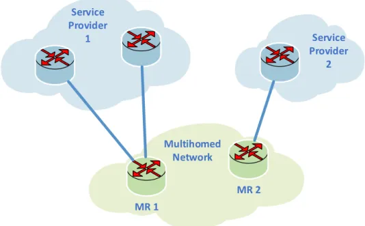
End-site multihoming, instead, where a site uses multiple connections to the Internet to meet objectives such as increasing network reliability or improving performance, is a common network configuration.
MR 1 MR 2 Service Provider 1 Service Provider 2 Multihomed Network
Figure 1.2: Multihomed Network
Figure 1.2 illustrates a multihomed site, which has connections to two service providers. A multihomed network can have multiple Mobile Router (MR), such as, for example, MR 1 connecting to Internet Service Provider 1
andMR2 connecting to Internet Service Provider 2. Moreover, a single router
can have several external interfaces that connect to the same or different service providers, as the example of MR 1.
Multihoming has gained attention over the last few years, mainly due to the potential benefits. In particular, multihoming solutions aim to achieve the following goals: resilience, ubiquity, load balancing/sharing and flow dis-tribution.
The diversity of multiple interfaces/paths can improve resilience since in case of failure of one interface/path, another can be employed to provide connectivity. For instance, a “primary-backup” model is adopted by Stream Control Transport Protocol (SCTP): if the primary path fails, the backup path can be used seamlessly without causing any application-layer service interruption. So, multiple network interfaces, in particular when used in a mobile and wireless network environment, enable ubiquitous access to the Internet over different media.
Load sharing goes one step further than the primary-backup model, as multiple interfaces/paths can be used simultaneously to improve throughput. For example, Iyengar et al. describe how one can perform concurrent multiple transfers using base SCTP [26].
Flow distribution, or flow stripping, offers an even finer granularity than load sharing. For many, flow distribution is the ultimate goal to achieve, as it implicitly means that all previous goals are also attained. Flows are stripped, perhaps even dynamically, according to policies and preferences aiming to reduce cost, optimize bandwidth use, and minimize the effect of bottlenecks to delay-sensitive applications, among others. Such policies can be defined by users or service providers.
1.1.2 Support strategies
Multihoming support could potentially be added at any layer of the protocol stack. The designer’s choice, of course, comes with certain advantages and disadvantages, and one needs to consider thoroughly the tradeoffs as well as the complexity of each solution. Deployment considerations need also to be addressed early on. In general, there are two possible approaches for introducing multihoming. On the one hand, a multihoming proposal may be completely transparent to upper layers, in such a way that there
1.1 Multihoming Base Concepts and Goals 9 isno disruption to ongoing sessions. On the other hand, the solution may not be transparent, but allows upper layers to participate in multihoming management and operation.
The first guideline that should be considered relates to the locator/iden-tifier split. Recently, the impossibility of the current Internet’s architecture to scale with the routing table size (see Figure 1.3) was deemed in an Internet Architecture Board (IAB) workshop as one of its most important problems [34], and after a detailed analysis, the overloading of IP address semantics with both location and identity, has been determined as the main source of this limitation [16]. Conventional IParchitectures assume that the transport layer endpoints are the same entities as those used by the network layer. Thus, multihoming support based on a locator/identifier split requires the transport layer identity to be decoupled from the network layer locator in order to allow multiple forwarding paths to be used by a single transport ses-sion. Different approaches can be considered, either by modifying an existing protocol layer or by introducing a new layer. With the new layer approach, upper layer protocols (e.g. applications) use endpoint identifiers to uniquely identify a session while the lower layer protocols (e.g. network) employ loca-tors. If this approach is used, a mapping between an identifier and a locator is necessary. In a multihoming context, the identifier/locator mapping must be assured by a dynamic process so that a session can include different fea-tures, such as constant endpoint identifiers throughout the session lifetime, and modification of locators to maintain end-to-end reachability [50].
Another recommendation for end-site multihoming includes the modi-fication of a site exit-router. In fact, end-site multihoming can be also assured by a network element like, for instance, an exit-router which performs packet rewriting for a given locator of a correspondent node. Nevertheless, this type of approach raises security concerns, which might be difficult to overcome. Redirection attacks are such an example, which may compromise routing, since packets for a destination can be redirected to any location. Thus, the host should always be able to perform the endpoint-to-locator mapping on its own [50].
0 25000 50000 75000 100000 125000 150000 175000 200000 225000 250000 275000 300000 325000 350000 375000 400000 425000 450000 475000 500000 525000 550000 575000 600000 625000 650000 1988 1989 1990 1991 1992 1993 1994 1995 1996 1997 1998 1999 2000 2001 2002 2003 2004 2005 2006 2007 2008 2009 2010 2011 2012 2013 2014 2015 2016
Figure 1.3: Active BGPentries (FIB)
1.1.3 Other related concepts
Multihoming is lately associated with other concepts, including multiaddress-ing, overlapping networks, multiple interfaces, overlay routmultiaddress-ing, scalability, security and policy.
Multiaddressing corresponds to a configuration where multiple addresses are assigned to a given host based on prefixes advertised in different connections.
Overlapping networks correspond to networks that are configured in a way that there is a common area of coverage. Typically, mobile and wireless end-nodes connecting to these (overlapping) networks must have multiple interfaces, each one specific to the technology sustain-ing the respective network.
Overlay routing is associated with inter-domain routing techniques that improve fault-tolerance and is only applied in an end-site context. Scalability is of essence in any network architecture and multihoming is
not an exception: multihoming architectures should be scalable and need to strive to minimize the impact on routers and end hosts. Basic connectivity must be always provided and if any modification is required
1.2 Consequences of Mobility 11 it should be in the form of logically separating added functions from existing ones.
Security is also paramount for future architectures. Multihoming propos-als should not introduce new security threats. For instance, multihom-ing solutions should be resilient to redirection attacks that compromise routing, new packet injection attacks (malicious senders can inject bo-gus packets into the packet stream between two communicating peers) and flooding attacks, which are normally associated with DoS attacks [50].
Policy is the set of rules which define in some circumstances how it is pos-sible to route traffic of a particular type (e.g. protocol) via particular transit providers. This can be done if the devices in the site—which source or sink that traffic—can be isolated to a set of addresses to which a special export policy can be applied [3].
1.2 Consequences of Mobility
1.2.1 Networks topology
As said, driven by the growing ubiquity of the Internet and a plethora of mo-bile devices with communication capabilities, distributed systems and com-plex applications are now the normality. The networks in which these appli-cations must operate are inherently dynamic; typically large and completely decentralized, so that each node can have an accurate view of only its local vicinity. Such networks change over time, as nodes join, leave, and move around, and as communication links appear and disappear.
In some networks (e.g. peer-to-peer), nodes participate only for a short period of time and the topology can change at a high rate. In wireless ad hoc networks, nodes are mobile and move around unpredictably [30]. Much work has gone into developing algorithms to work in networks that eventually stabilize and stop changing, but there is not a suitable ground for reasoning about truly dynamic networks yet.
1.2.2 Security issues
The general lesson on network protocol security is that plaintext secrets (verification tags, secret sequence numbers, nonces, etc.) that can be used in more than one message are more vulnerable with multihomed or mobile endpoints than in a static setting. They may still be acceptable as security mechanisms if the rate of change is slow and connection lifetimes limited, but actually this is not always so.
An assumption made in the standard transport-layer protocol (e.g. in SCTP) is that the transport addresses belong to the association endpoints until the end of the association lifetime. The danger of this assumption is that if the endpoint loses control of an address and the address is subsequently allocated to another node, the peer will continue to send packets to the lost address. The new owner of the address will receive the packets and learn all plaintext secrets in them. If the new owner of the address is malicious, it may use this information for spoofing attacks, but the risk of attacks caused by this vulnerability is small. Multihomed endpoints usually do their best to ensure that they retain all their addresses throughout the association lifetime, for example, by using only statically configured IPaddresses.
Nevertheless, in the mobility-protocol design it should be considered what happens to the old addresses of the mobile node, and the possibility that an attacker gains control of one.
In a general-purpose multihoming protocol, furthermore, there is also the possibility that the endpoints sometimes make mistakes about their address sets and even purposely misrepresent them. Also it is implicit that it is not possible to expect there to be any application-level verification or recovery mechanism that would mitigate the consequences of such false information. Thus, protocol engineers need to worry about attacks where the endpoints lie about their addresses, or more in general, in any multihoming or mobility protocol, must be considered the possibility of an endpoint making false claims about its addresses.
But not only. An address conflict in a telephony signaling protocol is probably an operator error and it is best to report the error and let the
1.3 Multihoming solutions 13 operator resolve it. The situation changes when a general-purpose multi-homing protocol is considered. There may not be any operator that could help, and thus it is essential to either avoid the conflicts or to resolve them automatically at the layer in which the conflict happens [7].
1.3 Multihoming solutions
An ideal multihoming solution which provides seamless mobility should meet the following requirements:
End-user transparency: the roaming should be completed as quickly as possible; the user should not notice any communication or service inter-ruption, or if that is not possible, the interruptions should be reduced in duration as well as in frequency.
Network transparency: applications should use only FQDNs for commu-nications; protocols should handle multihoming without affecting the upper layers.
Legacy compatibility: the solution should be fully compatible with the legacy infrastructure in terms of entities and protocols.
Quality of Service (QoS): node mobility should be managed in accord with the definedQoS.
Full mobility: nodes should not be aware of their mobility.
NAT-friendly: the solution should be compatible with possible Network Address Translation (NAT) policies.
As a consequence of its implementation complexity, multihoming is not supported by any widespread user application yet, nor by standard network devices. However, some working multihoming protocol implementations al-ready are in use on enterprise network routers.
An example is Cisco IOS1 [14] sinceSCTPis supported in order to
specifi-cally enhance reliability through support of multihoming at either end or both ends of the network association. It is not explicitly configured on routers by default, but it underlies several Cisco applications. Also LISP is supported
by Cisco IOS with outstanding performances [13] but the implementation is not opensource.
Praveen et al. have developed a Linux-based multihoming solution that consists of an outgoing load balancer and an incoming load balancer, par-ticularly suitable for small and medium enterprises [44]. The outgoing load balancer does policy-based routing to choose the best link for each type of traffic. It calculates the characteristics of the paths via each of the ISPs to the most frequently accessed destinations. The best link is chosen based on the path characteristic that is relevant to the application protocol of the packet, as determined by the user-defined policy. For infrequently visited destinations, a global policy that considers the first hop connectivity to the ISPs is used. The incoming load balancer distributes the load on the servers within the network among the links to theISPs in the ratio of available band-widths on these links by modifying the DNS entries appropriately. Finally, both the incoming and outgoing load balancers do dead gateway detection to minimize downtime.
Other solutions have been developed and analyzed but with controversial outcomes. For example, Borsari presented a work about VoIP multihoming support on Symbian [10] where the reusability-oriented code modifications were in unavoidable conflict with the performance and the energy efficiency aspects, which are gravely predominant on mobile devices.
Chapter 2
Network Protocols for
Multihoming
When a mobile Internet host changes its location and its point of access to the Internet changes, its IP address typically changes. The aim of mobility protocols is to solve the following two problems: to enable continuous com-munication over address changes, and to provide a reachability mechanism whenever the mobile is connected to the Internet. Mobility solutions exist for all major protocol layers. Link-layer mobility protocols avoid IP address changes. Network-layer protocols (e.g. Mobile IP (MIP)) hide them from the layers above. Transport-layer mobility protocols maintain a continuous connection between two endpoints over address changes. Higher, session and application-layer solutions re-establish transport-layer connections after an address change.
A multihomed Internet host usually has multiple IP addresses. While the goal of mobility protocols is to enable communication for moving hosts, the aim of multihoming is typically to increase reliability in a static setting: when one address fails, communication is switched to another one. However, despite their different goals, mobility and multihoming can be seen as two flavors of the same phenomenon, dynamic multi-addressing, that is the prop-erty of a multihomed or mobile endpoint of having a set of IPaddresses that changes dynamically [7].
In the following sections, the most important multihoming protocols are synthetically introduced.
2.1 Site Multihoming by
IPv6
Intermediation
2.1.1 Overview and Goals
The Site Multihoming by IPv6 Intermediation (SHIM6) protocol is a site-multihoming solution in the sense that it allows existing communication to continue when a site that has multiple connections to the Internet experiences an outage on a subset of these connections or further upstream. However, SHIM6 processing is performed in individual hosts rather than through site-wide mechanisms.
The goals of SHIM6 are:
• to preserve established communications in the presence of certain classes of failures, for example, Transmission Control Protocol (TCP) connec-tions and User Datagram Protocol (UDP) streams;
• to have minimal impact on upper-layer protocols in general and on transport protocols and applications in particular;
• to address the security threats in IP version 6 (IPv6) through a com-bination of the Hash-Based Address (HBA)/Cryptographic Generated Address (CGA) approach;
• to not require an extra roundtrip up front to set up shim-specific state. Instead, allow the upper-layer traffic (e.g. TCP) to flow as normal and defer the set up of the shim state until some number of packets have been exchanged;
• to take advantage of multiple locators/addresses for load spreading so that different sets of communication to a host (e.g. different connec-tions) might use different locators of the host.1
The problem to solve is the end-site multihoming, with the ability to have the set of site addresses change over time due to site renumbering.
1Notice that this might cause load to be spread unevenly; thus, the term “load
2.1 Site Multihoming by IPv6Intermediation 17 Further, it is assumed that such changes to the set of locator addresses can be relatively slow and managed: slow enough to allow updates to the Domain Name System (DNS) to propagate.
The SHIM6 proposal does not fully separate the identifier and locator functions that have traditionally been overloaded in theIPaddress. However, the term “identifier” or, more specifically, Upper-Layer IDentifier (ULID), refers to the identifying function of an IPv6address. “Locator” refers to the network-layer routing and forwarding properties of an IPv6address.
2.1.2 Protocol insights
Transport Protocol
SHIM6 shim layer
Frag/reass
Dest opts
IP
IP endpoint sub-layer
IP routing sub-layer
Figure 2.1: SHIM6 Protocol Stack
The proposal uses a multihoming shim layer within theIPlayer, as shown in Figure 2.1, in order to provide Upper-Layer Protocol (ULP) independence. The multihoming shim layer behaves as if it is associated with an extension header, which would be placed after any routing-related headers in the packet (such as any hop-by-hop ptions). However, when the locator pair is theULID pair, there is no data that needs to be carried in an extension header; thus, none is needed in that case.
Layering the fragmentation header above the multihoming shim makes reassembly robust in the case that there is broken multi-path routing that results in using different paths, hence potentially different source locators, for different fragments. Thus, the multihoming shim layer is placed between
the IPendpoint sub-layer, which handles fragmentation and reassembly, and the IP routing sub-layer, which selects the next hop and interface to use for sending out packets.
Applications and upper-layer protocols use ULIDs that the SHIM6 layer maps to/from different locators. The SHIM6 layer maintains state, called “ULID-pair context”, per ULID pair in order to perform this mapping. The mapping is performed consistently at the sender and the receiver so that ULPs see packets that appear to be sent using ULIDs from end to end. This property is maintained even though the packets travel through the network containing locators in the IP address fields, and even though those locators may be changed by the transmitting SHIM6 layer.
The context state is maintained per remote ULID (approximately per peer host) and not at any finer granularity. In particular, the context state is independent of the ULPs and any ULP connections. However, the forking capability enablesSHIM6-aware ULPs to use more than one locator pair at a time for a single ULID pair.
The result of this consistent mapping is that there is no impact on the ULPs, and in particular, there is no impact on pseudo-header checksums and connection identification.
Conceptually, one could view this approach as if bothULIDs and locators are present in every packet, and as if a header-compression mechanism is ap-plied that removes the need for theULIDs to be carried in the packets once the compression state has been established. In order for the receiver to re-create a packet with the correct ULIDs, there is a need to include some “compres-sion tag” in the data packets. This serves to indicate the correct context to use for decompression when the locator pair in the packet is insufficient to uniquely identify the context.
There are different types of interactions between theSHIM6layer and other protocols. Those interactions are influenced by the usage of the addresses in these other protocols and the impact of the SHIM6mapping on these usages. A detailed analysis of the interactions of different protocols, includingSCTP, MIP, and Host Identity Protocol (HIP), can be found in [2]. Moreover, some applications may need to have a richer interaction with the SHIM6 sublayer.
2.2 Host Identity Protocol 19 Sender A src ULID(A)=L1(A) dst ULID(B)=L1(B) ULP src L2(A) dst L3(B) Multihoming shim IP Receiver B src ULID(A)=L1(A) dst ULID(B)=L1(B) ULP src L2(A) dst L3(B) Multihoming shim IP
Figure 2.2: SHIM6Mapping with Changed Locators
In order to enable that, an Application Programming Interface (API) has been defined to enable greater control and information exchange for those applications that need it [40].
2.2 Host Identity Protocol
The Host Identity Protocol (HIP) allows consenting hosts to securely estab-lish and maintain shared IP-layer state, allowing separation of the identifier and locator roles of IPaddresses, thereby enabling continuity of communica-tions across IP address changes. HIP is based on a Sigma-compliant
Diffie-Hellman key exchange, using public key identifiers from a new Host Identity namespace for mutual peer authentication. The protocol is designed to be resistant to Denial-of-Service (DoS) and Man-in-the-Middle (MitM) attacks. When used together with another suitable security protocol, such as the Encapsulated Security Payload (ESP), it provides integrity protection and optional encryption for upper-layer protocols, such as TCPand UDP [37].
2.2.1
HIPArchitecture
The Internet has two important global namespaces: IP addresses and DNS names. These two namespaces have a set of features and abstractions that have powered the Internet to what it is today. They also have a number of weaknesses. Moreover, semantic overloading and functionality extensions have greatly complicated these namespaces.
The Host Identity namespace fills an important gap between the IP and DNS namespaces: it consists of Host Identifiers. A Host Identifier (HI) is cryptographic in its nature—it is the public key of an asymmetric key-pair. Each host will have at least one Host Identity, but it will typically have more than one. Each Host Identity uniquely identifies a single host (e.g. two hosts cannot have the same Host Identity). The Host Identity, and the corresponding Host Identifier, can be either public (e.g. published in the DNS) or unpublished. Client systems will tend to have both public and unpublished Identities.
There is a subtle but important difference between Host Identities and Host Identifiers. An Identity refers to the abstract entity that is identified. An Identifier, on the other hand, refers to the concrete bit pattern that is used in the identification process.
When HIP is used, the actual payload traffic between two HIP hosts is typically, but not necessarily, protected with IP Security (IPSec). The Host Identities are used to create the needed IPSec Security Associations and to authenticate the hosts. WhenIPSecis used, the actual payloadIPpackets do not differ in any way from standardIPSec-protected IP packets [36].
2.2 Host Identity Protocol 21 FQDN or IP Address IP Address, Port IP Address Application Transport Network IP FQDN or Host ID Host ID, Port
Host ID IP Address
HIP
MAC Address
Physical MAC Address
Host Identity
Figure 2.3: HIP Architecture
the Host Identity Tag (HIT). As said, the HI is a public key and directly represents the Identity. Since there are different public key algorithms that can be used with different key lengths, theHIis not good for use as a packet identifier, or as an index into the various operational tables needed to sup-port HIP. Consequently, a hash of the HI, the HIT, becomes the operational representation. It is 128b long and is used in the HIPpayloads and to index the corresponding state in the end hosts. The HIThas an important security property in that it is self-certifying [37].
2.2.2
HIPBase Exchange
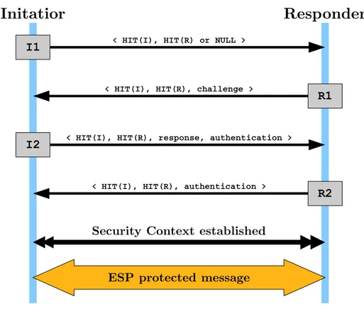
The HIP base exchange is a two-party cryptographic protocol used to estab-lish communications context between hosts. The base exchange is a Sigma-compliant four-packet exchange. The first party is called the Initiator and the second party the Responder. The four-packet design helps to make HIP DoS resilient. The protocol exchanges Diffie-Hellman keys in the 2nd and
3rd packets, and authenticates the parties in the 3rd and 4th packets.
the Initiator completing it in the 3rd packet before the Responder stores any
state from the exchange.
Initatior
Responder
I1 < HIT(I), HIT(R) or NULL >
R1
< HIT(I), HIT(R), challenge >
I2 < HIT(I), HIT(R), response, authentication >
< HIT(I), HIT(R), authentication >
R2 Security Context established
ESP protected message
Figure 2.4: HIPfour-way handshaking
The exchange can use the Diffie-Hellman output to encrypt the Host Identity of the Initiator in the 3rd packet or the Host Identity may instead be
sent unencrypted. The Responder’s Host Identity is not protected. It should be noted, however, that both the Initiator’s and the Responder’s HITs are transported as such (in cleartext) in the packets, allowing an eavesdropper with a priori knowledge about the parties to verify their identities. Data packets start to flow after the 4th packet. The 3rd and 4th HIP packets may
carry a data payload in the future. However, the details of this are to be defined later as more implementation experience is gained.
Finally,HIPis designed as an end-to-end authentication and key establish-ment protocol, to be used withESP and other end-to-end security protocols,
2.2 Host Identity Protocol 23 but the base protocol does not cover all the fine-grained policy control found in Internet Key Exchange (IKE) (that, for example, allows IKE to support complex gateway policies). Thus, HIPis not a replacement for IKE [37].
2.2.3 End-host Mobility and Multihoming
Architecturally, HIP provides for a different binding of transport-layer pro-tocols. That is, the transport-layer associations (e.g. TCP connections and UDPassociations) are no longer bound toIPaddresses but to Host Identities. It is possible that a single physical computer hosts several logical end-points. With HIP, each of these end-points would have a distinct Host tity. Furthermore, since the transport associations are bound to Host Iden-tities, HIP provides for process migration and clustered servers. That is, if a Host Identity is moved from one physical computer to another, it is also possible to simultaneously move all the transport associations without break-ing them. Similarly, if it is possible to distribute the processbreak-ing of a sbreak-ingle Host Identity over several physical computers,HIPprovides for cluster-based services without any changes at the client end-point.
As said, HIPdecouples the transport from the internetworking layer, and binds the transport associations to the Host Identities. Consequently, HIP can provide for a degree of internetworking mobility and multihoming at a low infrastructure cost. HIP mobility includes IP address changes (via any method) to either party. Thus, a system is considered mobile if itsIPaddress can change dynamically for any reason like Point-to-Point Protocol (PPP), Dynamic Host Configuration Protocol (DHCP),IPv6prefix reassignments, or a NAT device remapping its translation. Likewise, a system is considered multihomed if it has more than one globally routable IPaddress at the same time. HIPlinksIPaddresses together, when multipleIPaddresses correspond to the same Host Identity, and if one address becomes unusable, or a more preferred address becomes available, existing transport associations can easily be moved to another address.
When a node moves while communication is already ongoing, address changes are rather straightforward. The peer of the mobile node can just
accept a HIP or an integrity protected IPSec packet from any address and ignore the source address. However, a mobile node must send aHIPreaddress packet to inform the peer of the new address(es), and the peer must verify that the mobile node is reachable through these addresses [36].
More lately, Pierrel et al. introduced a policy system for simultaneous multiaccess based on HIPcalled HIPSImultaneous Multi-Access (SIMA) [43]. The proposal extends HIP by allowing flows to use different paths indepen-dently of each other, since HIP does not support load sharing. To enable flow distribution, flows are identified by source and destination ports and by the HIT. The RendezVous Server is also extended to be able to store flow policies. Whilst these policies define the usage rules of the available inter-faces, the proposal does not detail the policy specification (e.g. rules actions, interface priority, and cost) [50].
2.3 Identifier/Locator Network Protocol
Since Identifier/Locator Network Protocol (ILNP) has been recommended by Internet Engineering Task Force (IETF) in [31] for future routing architec-ture, the protocol is presented here. Basically, IETF has found ILNP to be a clean solution since it separates location from identity in a clear, straightfor-ward way that is consistent with the remainder of the Internet architecture: unlike the many map-and-encap proposals, there are no complications due to tunneling, indirection, or semantics that shift over the lifetime of a packet’s delivery.
2.3.1 Architectural Overview
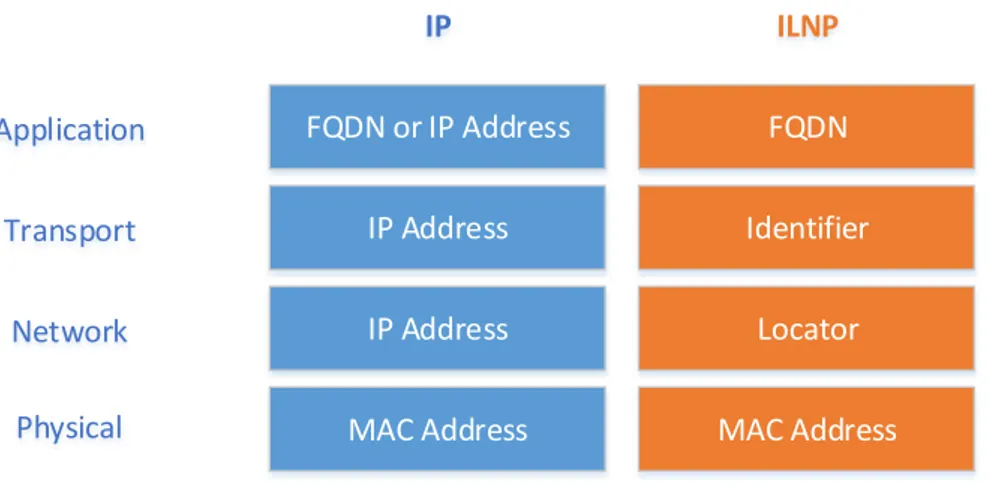
ILNP takes a different approach to naming of communication objects within the network stack. Two new data types are introduced which subsume the role of the IP Address at the network and transport layers in the current IP architecture. ILNP explicitly replaces the use of IP Addresses with two distinct name spaces, each having distinct and different semantics:
2.3 Identifier/Locator Network Protocol 25 Locator: a topologically bound name for anIP subnetwork.
FQDN or IP Address IP Address IP Address MAC Address Application Transport Network Physical IP FQDN Identifier Locator MAC Address ILNP
Figure 2.5: ILNPArchitecture
The use of these two new namespaces in comparison to IP is shown in Figure 2.5. If an application uses a Fully Qualified Domain Name (FQDN) at the application-layer, rather than an IP Address or other lower-layer identi-fier, then the application perceives no architectural difference betweenIPand ILNP. In fact,ILNPdoes not require applications to be rewritten to use a new NetworkingAPI. So existing “well-behaved” IP-based applications should be able to work over ILNP as is.
InILNP, transport-layer protocols use only an end-to-end, non-topological node Identifier in any transport-layer session state. It is important to note that the node Identifier names the node, not a specific interface of the node. In this way, it has different semantics and properties than either the IP Ad-dress or the IP interface identifier. Anyway, the use of the ILNP Identifier value within application-layer protocols is not recommended. Instead, the use of either a FQDN or some different topology-independent namespace is recommended.
At the network-layer, Locator values, which have topological significance, are used for routing and forwarding of ILNP packets, but Locators are not used in upper-layer protocols.
As well as the new namespaces, another significant difference in ILNP is that there is no binding of a routable name to an interface, or Sub-Network Point of Attachment (SNPA), as there is inIP. The existence of such a binding inIPeffectively binds transport protocol flows to a specific, single interface on a node. Also, applications that includeIPAddresses in their application-layer session state effectively bind to a specific, single interface on a node. Dynamic bindings exist between Identifier values and associated Locator values, as well as between {Identifier, Locator} pairs and (physical or logical) interfaces on the node.
This change enhances the Internet Architecture by adding crisp and clear semantics for the Identifier and for the Locator, removing the overloaded semantics of theIPAddress, by updating end-system protocols, but without requiring any router or backbone changes, exceptedDNS. InILNP, the closest approximation to anIPAddress is an Identifier-Locator Vector (I-LV),2 which
is a given binding between an Identifier and Locator pair. Where, today, IPpackets have:
• Source IPAddress, Destination IP Address Instead, ILNP packets have:
• Source I-LV, Destination I-LV
Hence, with these naming enhancements, the Internet Architecture is improved by adding explicit harmonised support for many functions, such as multihoming, mobility, andIPSec.
Network-layer
Today, network-layer IPsessions have 2 components: • Source IPAddress (A_S)
• Destination IPAddress (A_D)
Instead, network-layer ILNP sessions have 4 components: • Source Locator(s) (L_S)
• Source Identifier(s) (I_S) • Destination Locator(s) (L_D)
2However, it must be emphasised that the
2.3 Identifier/Locator Network Protocol 27 • Destination Identifier(s) (L_S)
Incidentally the phrase “ILNP session” refers to an ILNP-based network-layer session, having the 4 components in the definition above. For engi-neering efficiency, multiple transport-layer sessions between a pair of ILNP correspondents normally share a single ILNP session.
Transport-layer
Today, transport-layer sessions using IP include these 5 components: • Source IP Address (A_S)
• Destination IPAddress (A_D)
• Transport-layer protocol (e.g. UDP,TCP, SCTP) • Source transport-layer port number (P_S) • Destination transport-layer port number (P_D)
Instead, transport-layer sessions using ILNP include these 5 components: • Source Identifier (I_S)
• Destination Identifier (I_D)
• Transport-layer protocol (e.g. UDP,TCP, SCTP) • Source transport-layer port number (P_S) • Destination transport-layer port number (P_D)
IP Address and I-LV
Historically, anIPAddress has been considered to be an atomic datum, even though it is recognised that an IP Address has an internal structure: the network prefix plus either the host ID (IP version 4 (IPv4)) or the interface identifier (IPv6). However, this internal structure has not been used in end-system protocols; instead, all the bits of theIP Address are used.3
While it is possible to say that an I-LV is an approximation to an IP Address of today, it should be understood that an I-LV is not an atomic
3Additionally, in
IPv4, the IPv4 subnet mask uses bits from the host IDentity (ID),
a further confusion of the structure, even thought it is an extremely useful engineering mechanism.
datum, being a pairing of two data types, an Identifier and a Locator; and that it has different semantics and properties to anIP Address.
2.3.2 Node Identifier
Identifiers, also called Node IDentifier (NID), are non-topological values that identify an ILNP node. A node might be a physical node or a virtual node. For example, a single physical device might contain multiple independent virtual nodes. Alternately, a single virtual device might be composed from multiple physical devices.
A node may have multiple Identifier values associated with it, which may be used concurrently. In normal operation, when a node is responding to a received ILNP packet that creates a new network-layer session, the correct NIDvalue to use for that network-layer session with that correspondent node will be learned from the received ILNP packet. In normal operation, when a node is initiating communication with a correspondent node, the correct I value to use for that session with that correspondent node will be learned either through the application-layer naming, through DNS name resolution, or through some alternative name resolution system.
Once aNIDvalue has been used to establish a transport-layer session, that Node Identifier value forms part of the end-to-end (invariant) transport-layer session state and so must remain fixed for the duration of that session. And this means, for example, that throughout the duration of a givenTCPsession, the Source NIDand Destination NID values will not change.
In normal operation, a node will not change its set of valid Identifier values frequently. However, a node may change this set over time, for example, in an effort to provide identity obfuscation. When a node has more than one NIDvalue concurrently, the node might have multiple concurrentILNPsessions with some correspondent node, in which caseNID values may differ between the different concurrent ILNPsessions.
2.4 Locator/Identifier Separation Protocol 29
2.3.3 Multihoming and Multi-Path Transport
For multihoming, there are two main cases and one sub-case to consider: Host-Multihoming (H-MH): a single host is, individually, connected to
multiple upstream links, via separate routing paths, and those multiple paths are used by that host as it wishes. That is, use of multiple up-stream links is managed by the single host itself. For example, the host might have multiple valid Locator values on a single interface, with each Locator value being associated with a different upstream link (provider). Multi-Path Transport (MPT): multiple paths are used to transfer
data for an end-to-end session [33]. This can be considered a special case of H-MH.
Site-Multihoming (S-MH): a site network is connected to multiple up-stream links via separate routing paths, and hosts on the site are not necessarily aware of the multiple upstream paths. That is, the multiple upstream paths are managed, typically, through a site border router, or via the providers.
Essentially, for ILNP, multihoming is implemented by enabling multiple Locator values to be used simultaneously by a node, and dynamic, simulta-neous binding between one (or more) Identifier value(s) and multiple Locator values. Other details can be found in [6].
2.4 Locator/Identifier Separation Protocol
2.4.1 Overview
The Locator/Identifier Separation Protocol specifies an architecture for de-coupling host identity from its location information in the current address scheme. This separation is achieved by replacing the addresses currently used in the Internet with two separate name spaces: Endpoint IDentifier (EID), and Routing LOCator (RLOC). Host applications bind to host’s EID, which is used as the address for transport connections; while RLOCs are IPv4 or
IPv6 addresses used for routing through transit networks. In order to reach a host, identified by its EID, one must first find the current location of the host. Separating the host identity (EID) from its locator (RLOC) enables seamless endpoint mobility by allowing the applications to bind to a perma-nent address, the host’sEID. The location of the host can change many times during an ongoing connection. Each time, the Locator/Identifier Separation Protocol (LISP) tunnel routers will encapsulate the packets to the newRLOC, preserving the connection session from breaking [47].
2.4.2
LISPMapping System
RLOC Space EID-to-RLOC Mapping EID Space Non-LISP EID Space xTR PxTR xTR MS/MR xTR Prefix a.a.a.0/24 b.b.b.0/24 c.c.c.0/16 Next-hop e.f.g.h e.f.g.h i.j.k.l EID a.a.a.0/24 b.b.b.0/24 c.c.c.0/16 RLOC w.x.y.1 x.y.w.2 z.q.r.3 EID a.a.a.0/24 b.b.b.0/24 c.c.c.0/16 RLOC w.x.y.1 x.y.w.2 z.q.r.3 EID a.a.a.0/24 b.b.b.0/24 c.c.c.0/16 RLOC w.x.y.1 x.y.w.2 z.q.r.3
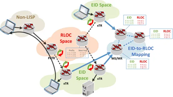
Figure 2.6: LISPArchitecture
As shown in Figure 2.6, the LISP Mapping System is a central aspect of the LISP architecture. It is a publicly accessible service that publishes location information associated with EIDs (EID-to-RLOC mappings). Main elements of LISPMapping System are Map Servers and Map Resolvers. EID -to-RLOCmappings are stored in Map Servers. Each Map Server is associated with a partition of the EID name space, and stores the location information
2.4 Locator/Identifier Separation Protocol 31 for those EIDprefixes. Therefore, each LISPmobile node is associated with a specific Map Server where it registers itsEID-to-RLOCmapping, and updates it according to its movement. In this context, Map Servers have assigned a set of EIDs and delegate them to either LISP tunnel routers or mobile nodes. Map Resolvers are used as an interface to the mapping system for look-ing up EID location information; they have a similar functionality as DNS resolvers have in today’s Internet: LISP mobile nodes send EID lookup re-quests (Map Request) to the mapping system through Map Resolvers [47].
2.4.3
LISP-MNThe lightweight tunnel router is the implementation of LISP Mobile Node (LISP-MN) on the endpoint or mobile node. Mobile node tunnel routers are used to encapsulate outgoing packets in a LISP header based on RLOCs be-fore leaving the mobile node, and to remove the LISP header from incoming packets before sending them to upper layers ultimately reaching the desti-nation application. The LISP-MN protocol is then best understood as the concatenation of three different phases [47]:
• Registering EIDand obtaining an RLOC;
• Signaling EID-to-RLOC bindings and transmitting data-packets; • Handover.
These phases are now explained in detail. Registering EID and obtaining an RLOC
Each LISP-MN is configured with at least one EID. As said before, an EID is either a standard (/32) IPv4 or (/128) IPv6 address, identifies the node uniquely and remains static independently of its location. If the node has also a DNS entry, this entry returns the EID which is typically assigned by the Map Server provider.4
In order to connect to the Internet, the LISP-MN also needs at least an RLOC. RLOCs are obtained by traditional mechanisms such as DHCPor
con-4In
figured manually and are location dependent. This means that as the mobile node roams across providers, it will obtain a different RLOC in each loca-tion. For each new RLOC obtained by the LISP-MN, the node has to inform about the new EID-to-RLOC binding to its Map Server. In order to do so LISP defines the Map Register signaling message that includes the EID and the RLOC. The node may include multipleRLOCs if the node is multihomed and LISP supports any combination of IPv4 and IPv6 for EIDs and RLOCs. The LISP-MN and the Map Server share a pre-configured key5 which is used
to sign the Map Register to ensure authentication. Once the Map Server receives a valid Map Register containing an EID-to-RLOC mapping it will it make it accessible throughout the Mapping System [47].
11.0.0.1 Mapping System LISP Site 2.0.0.0/24 S Provider B 11.0.0.0/8 S2 Provider Y 13.0.0.0/8 MR 65.1.1.1 S1 Provider X 12.0.0.0/8 MS 66.2.2.2 Provider A 10.0.0.0/8 10.0.0.1 LISP-MN 3.0.0.3/32 12.0.0.2 13.0.0.2 12.0.0.2 66.2.2.2 LISP Map-Register (UDP 4342)
SHA-1
3.0.0.3/32 12.0.0.2
3.0.0.3/32 13.0.0.2
Figure 2.7: Registering an EID-to-RLOCbinding
ALISP-MNis configured with theEID3.0.0.3/32 and twoRLOCs from two different providers X 12.0.0.2
and Y 13.0.0.2. TheMNregisters these two bindings 3.0.0.3/32→ 12.0.0.2 and 3.0.0.3/32 → 13.0.0.2 into its Map Server (identified with the address 66.2.2.2). TheMNand aMShave a pre-configured key and this Map Register message is signed and hence, authenticated.
5Again, in
2.4 Locator/Identifier Separation Protocol 33 Signaling EID-to-RLOC bindings and transmitting data-packets The static node first retrieves theEIDof the mobile node by querying theDNS and then transmits a packet addressed to thisEIDjust as in the plain Internet. The packet is routed until it reaches theLISPtunnel router. Upon reception, the tunnel router checks whether it knows the EID-to-RLOC binding or not. For this purpose each LISP node includes a data-structure called Map-cache which stores such information.
If the tunnel router’s Map-cache does not contain the binding for the destinationEID, it will trigger a Map-request message. This message is used to query the Mapping System for a particular binding: it is sent to the Map Resolver, which is typically co-located with the Map Server, and in turn, the Map Resolver forwards the Map-request message through the Mapping System that routes it, according to the destination EID, until it reaches the Map Server that provides mapping services to the Mobile Node (MN).
The Map Server then constructs a reply for the Map-request using an-other LISP defined message, the Map-reply. This message mainly contains the EID of the MN, the set of RLOCs that provide connectivity to the MN, and the priorities and weights of each locator which are used for ingress load-balancing. Finally the Map-reply also contains a Time-To-Live (TTL) that defines the amount of time for which this particular mapping is valid, and a nonce to avoid unsolicited replies. The Map-reply is sent directly to the tunnel router that will install this binding in its Map-cache and will use it to encapsulate packets towards the MN until the TTL expires. At this point it will request a fresh binding.
Typically, as in TCP, the node will reply with another data-packet ad-dressed to the EID of the static node. Since the Map-cache of the MN does not have the binding for suchEID, it will trigger a Map-request querying for the RLOCs of the LISP site. This Map-request, as in the previous case, will be routed through the Mapping System towards the Map Server servicing the site that in turn replies with a Map-reply. The mobile node, upon reception of this message, will install this binding in its Map-cache and will start to encapsulate data packets directly to the locators of the LISP site according
to whatever policies have been defined (weight and priorities). Such data-packets are decapsulated at the tunnel router and forwarded, as in the plain Internet, to the final destination [47].
Handover
When theMNchanges its point of attachment, it will regain connectivity in a new subnetwork, possibly serviced by a new provider. In this case it will first obtain a newRLOCand, as described before, will send the new EID-to-RLOC binding on its Map Server.
In order to resume existing connections, the MN has to update all the EID-to-RLOC bindings stored in the Map-cache of the routers with which it is communicating. To do so the MN will send a special signaling message called Solicit-Map-Request (SMR) to all these routers/mobile nodes. Upon reception of such message, the peering router/mobile node will trigger a Map-request addressed towards the EID of the soliciting MN. This message will be in turn forwarded by the Mapping System until it reaches the Map Server servicing the MN that will reply with a Map-reply containing the updatedRLOCs.
2.4.4
LISPand legacy internetworking
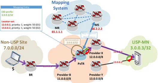
Communications between LISP nodes and legacy non-LISP enabled nodes are fasten by ad hoc LISP internetworking components called Proxy Tun-nel Router (PxTR). A PxTR attracts traffic by announcing, by means of Border Gateway Protocol (BGP), EID addresses. Then it queries the Map-ping System to obtain the correspondingRLOCbindings and encapsulate the data-packets towards them. Additionally, PxTRs also decapsulate packets sent by LISP-enabled sites and nodes towards the non-LISP Internet. This is done to avoid ingress filtering issues [47].
2.5 Stream Control Transport Protocol 35 11.0.0.1 Mapping System Non-LISP Site 7.0.0.0/24 S Provider B 11.0.0.0/8 BR Provider Y 13.0.0.0/8 MR 65.1.1.1 Provider X 12.0.0.0/8 MS 66.2.2.2 PxTR LISP-MN 3.0.0.3/32 12.0.0.2 13.0.0.2 EID-prefix: 3.0.0.3/32 Locator-set: 12.0.0.2, priority: 1, weight: 50 (D1) 13.0.0.2, priority: 1, weight: 50 (D2) Map-request Map-reply Mapping Entry BGP Announcement: 3.0.0.3/32
Figure 2.8: Internetworking with non-LISP sites
ThePxTR is announcing at the BGP DFZan aggregated EID prefix that covers the one configured at theMN. By means of thisBGP announcement, PxTRattracts traffic addressed to the EID of the MN
(3.0.0.3/32) and, upon reception of a data-packet, it queries the Mapping System to obtain the locator set (12.0.0.2 and 13.0.0.2) and proceeds to encapsulate packets. In turn, thePxTR is also used to decapsulate data-packets addressed to non-LISP sites.
2.5 Stream Control Transport Protocol
The Stream Control Transport Protocol (SCTP) is a reliable message-based transport protocol developed by the IETF that could replace TCP in some applications. SCTP allows endpoints to have multiple IP addresses for the purposes of fault tolerance and there is on-going work to extend the SCTP multihoming functions to support dynamic addressing and endpoint mobility [7].
2.5.1
SCTPOverview
The SCTP is a standard transport-layer protocol for the IPv4 and IPv6 In-ternet. SCTP was originally intended for the transport of Public Switched
Telephone Network (PSTN) telephony signaling messages over IP but it is now specified as a general-purpose alternative to TCP and UDP.
An SCTP association is a relationship between two SCTP endpoints. An endpoint is a set of transport addresses and a transport address consists of a network-layer address and a port number. In SCTP, all transport addresses of an endpoint must share the same port number. Thus, in practice, anSCTP endpoint is identified with a non-empty set of IPaddresses and a single port number. A pair of transport addresses is called path. Each transport address can belong to only one endpoint at a time, so, this means that no special endpoint identifiers are needed. The receiver of anSCTPpacket identifies the source and destination endpoints and the association to which the packet belongs based on the source and destination IP addresses and port numbers. An SCTP packet comprises a common header and zero or more chunks. The chunks may carry either SCTPsignaling information or user data (DATA chunk). Multiple chunks, such as user data and acknowledgements, may be bundled into one packet. Also, SCTP provides ordered and reliable multi-stream transport [7].
2.5.2 Protocol insights
SCTP Handshake
First, endpoints exchange random 32b nonces.6 The header of all but the
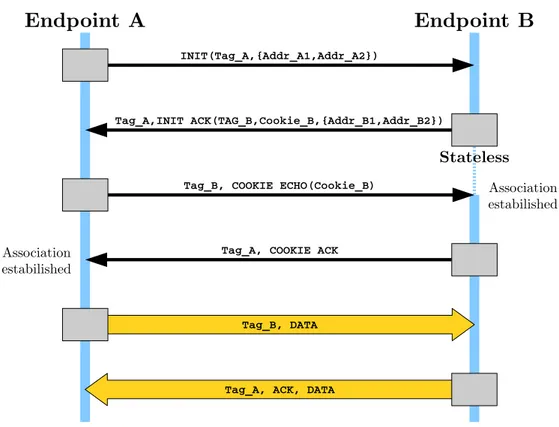
first packet from Endpoint A to B must include B’s nonce. Correspondingly, B must include A’s nonce in the header of all packet that it sends to A. The SCTPspecification calls the nonces “verification tags” (denoted by Tag_A and Tag_B in Figure 2.9). These verification tags serve the same security purpose as the randomly initialized sequence numbers in TCP, that is, they provide a level of security against packet spoofing.
During the SCTP handshake, each of the two endpoints may send to the other a list ofIPaddresses (in the INIT and INIT ACK chunks). Each endpoint
6Here and after I use the Internet Engineering Task Force (IEEE) 1541-2002 standard
2.5 Stream Control Transport Protocol 37
Endpoint A
Endpoint B
INIT(Tag_A,{Addr_A1,Addr_A2})
Tag_A,INIT ACK(TAG_B,Cookie_B,{Addr_B1,Addr_B2})
Tag_B, COOKIE ECHO(Cookie_B)
Tag_A, COOKIE ACK
Tag_B, DATA
Tag_A, ACK, DATA
Association estabilished Association
estabilished
Stateless
Figure 2.9: SCTPfour-way handshaking
selects one of the peer’s addresses as the primary destination address, and one of it owns addresses as the best source address for routing packets to the destination. If the choice is not mandated by the upper-layer protocol, the algorithm for choosing the destination address is implementation dependent. The typical choice is either the source address of the first received packet or the first address in the peer’s list.
An important feature of theSCTPhandshake is that the respondent (End-point B) remains stateless between sending the 2ndand receiving the 3rd
mes-sage. The respondent encodes the protocol state, including the contents of the INIT, into a state cookie, which it sends to the initiator (Endpoint A) in the INIT ACK. The initiator returns the cookie to the respondent in the COOKIE ECHO. This prevents state-exhaustion attacks similar to the TCP SYN flooding [7].