POLITECNICO DI MILANO
SCHOOL OF INDUSTRIAL AND INFORMATION
ENGINEERING
Master’s degree in Materials Engineering and Nanotechnology
BACTERIA ENTRAPMENT ENGINEERING
FOR FLOW MICROBIAL FUEL CELLS
Supervisor: Prof. Massimiliano Bestetti
Co-supervisor: Matteo Grattieri
Master thesis of:
Julia Anne Behring 882889
Acknowledgments
Before starting this thesis work, I wanted to thank all the people that believed in me and helped me realize this work.
First, I’m grateful to the institution of Politecnico di Milano and to prof. Massimiliano Bestetti: without his help and his availability, I wouldn’t have had the opportunity to write this work as well as having an amazing journey abroad learning both academic and life lessons. Secondly, I would like to thank Matteo Grattieri, my supervisor at University of Utah, for his knowledge, brilliance and originality that guided me throughout this work. Moreover, I need to thank Shelley Minteer and in general all Minteer’s group for giving me the opportunity to learn and have fun in a wonderful environment.
I want to thank my family for all their care, my mom for her determination, my dad for his rationality and all my siblings for their support and tenderness.
A special appreciation to my soon-to-be husband, for his affection and support. He is my guide and model; I’m grateful to have him by my side.
At last, all the ones that I couldn’t mention: friends, family and all the people who support me every day.
iii
Table of contents
BACTERIA ENTRAPMENT ENGINEERING FOR FLOW MICROBIAL FUEL CELLS ..I TABLE OF CONTENTS ... III INDEX OF FIGURES ... VI INDEX OF TABLES ... X LIST OF ABBREVIATIONS ... XI ABSTRACT ... XIII 1. INTRODUCTION ... 1 2. STATE OF ART ... 4
2.1MICROBIAL FUEL CELL’S FUNCTIONING... 4
2.2ELECTRON TRANSFER BETWEEN SUBSTRATE, ELECTRODE AND MICROORGANISMS ... 5
2.2.1 Direct electron transfer ... 6
2.2.2 Mediated electron transfer... 7
2.3 MICROBIAL FUEL CELL’S CONFIGURATIONS ... 8
2.3.1 Double-chamber microbial fuel cell ... 8
2.3.2 Single-chamber microbial fuel cell ... 10
2.4ELECTRODE MATERIAL... 11
2.4.1 Anode material ... 11
2.4.2 Surface improvements ... 14
2.4.3 Cathode materials ... 15
iv
2.6BACKGROUND OF PREVIOUS WORKS... 18
2.6.1 Bacteria isolation and characterization ... 18
2.6.2 Alginate encapsulation[9] ... 19
2.6.3 Transition from batch to flow ... 20
3. MATERIALS AND METHODS ... 21
3.1BACTERIAL GROWTH ... 21
3.2PREPARATION AND ENGINEERING OF ALGINATE CAPSULES ... 22
3.3PREPARATION OF THE ELECTRODES ... 23
3.3.1 Anode ... 23 3.3.2 Cathode ... 23 3.4 CELL SET-UP ... 24 3.4.1 Flow MFC ... 24 3.4.2 Batch cell ... 25 3.5ELECTROCHEMICAL SET UP ... 26
3.6CHEMICAL OXYGEN DEMAND MONITORING ... 28
3.7COULOMBIC EFFICIENCY ... 28
4. RESULTS AND DISCUSSION ... 29
PART 1:COMPARISON OF ENGINEERED CAPSULES MFCS IN FLOW CONDITION [8] ... 29
4.1ELECTROCHEMICAL MEASUREMENTS ... 29
4.1.1 MFCs with AC modified capsules ... 29
4.1.2 MFCs with p-BQ modified capsules ... 38
4.2.DEGRADATION PERFORMANCE ... 52
4.3.COULOMBIC EFFICIENCY ... 57
PART 2COMPARISON OF ENGINEERED CAPSULES IN BATCH CONDITIONS ... 58
1. CONCLUSIONS ... 66
v
vi
Index of figures
Figure 1: Schematic of the functioning of a MFC 4
Figure 2: Schematic of the electron transfer mechanisms from the microorganism to the anode 6 Figure 3 [31]: Schematic of a double chamber microbial fuel cell 9 Figure 4 [31]: Schematic of a single chamber microbial fuel cell 10 Figure 5 [32]: Examples of common materials for anodes 12 Figure 6: Unmodified alginate (left), with 0.15 gL-1 AC (center), and with 0.5 gL-1 of AC (right) 22
Figure 7: Schematic of the flow MFC 25
Figure 8: Schematic of the batch cell configuration 26
Figure 9: Power curves for batch (green), flow (blue), flow MFC with engineered alginate capsules with 0.15 gL-1 AC (red) and 0.5 gL-1 AC (magenta) and control (black) obtained during
the first degradation cycle 30
Figure 10: Anodic quasi-stationary polarization curves of batch (green), flow (blue), flow MFC with engineered alginate capsules with 0.15 gL-1 AC (red) and 0.5 gL-1 AC (magenta)
and control (black) obtained during the first degradation cycle 32 Figure 11A: Anodic quasi-stationary polarization curves of batch MFCs at 24 (blue), 96 (green),
and 120 h of operation (red) 33
Figure 11B: Anodic quasi-stationary polarization curves of flow MFCs with 0.15 gL-1 AC engineered
capsules at 24 (blue), 96 (green), and 144 h (red) 3634 Figure 11C: Anodic quasi-stationary polarization curves of flow MFCs with 0.5 gL-1 AC engineered
capsules at 24 (blue), 96 (green), and 144 h (red) 3635 Figure 12: Scanning electron microscopy images for an anode utilized in a flow MFC using
composite alginate capsules prepared with 0.5 (A) and 0.15 gL-1 AC (B) 36
Figure 13: Cathodic quasi-stationary polarization curves of batch (green), flow (blue) and flow MFC with engineered alginate capsules with 0.15 gL-1 AC (red) and 0.5 gL-1 AC
(magenta) obtained during the first degradation cycle 37 Figure 14: Schematic of possible rearrangements of bacteria inside the capsules in the presence of
vii Figure 15: Scanning electron microscopy images for alginate capsules prepared without p-BQ
(left) and with 500 μM p-BQ (right) 39
Figure 16A: Power density curves for batch (green), flow (blue), flow MFC with engineered alginate capsules with 0.15 gL-1 AC (red), 0.5 gL-1 AC (magenta), 0.15 gL-1 AC with
500 μM p-BQ (best performance) (purple) and control (black) obtained during the
first degradation cycle 40
Figure 16B: Power density curves for batch (green), flow (blue), flow MFC with engineered alginate capsules with 0.15 gL-1 AC (red), 0.5 gL-1 AC (magenta), 0.15 gL-1 AC with
500 μM p-BQ (intermediate performance) (purple) and control (black) obtained
during the first degradation cycle 4041
Figure 17: Anodic quasi-stationary polarization curves of batch (green), flow (blue), flow MFC with engineered alginate capsules with 0.15 gL-1 AC (red), 0.5 gL-1 AC (magenta),
0.15 gL-1 AC with 500 μM p-BQ (intermediate performance) (cyan) and control (black)
obtained during the first degradation cycle 43
Figure 18A: Anodic quasi-stationary polarization curves of flow MFCs with 0.15 gL-1 AC with
500 μM p-BQ at 24 (blue), 96 (green), and 144 h (red) (run 1) 44 Figure 18B: Anodic quasi-stationary polarization curves of flow MFCs with 0.15 gL-1 AC with
500 μM p-BQ at 24 (blue) and 96 h (green) (run 2) 44 45 Figure 18C: Anodic quasi-stationary polarization curves of flow MFCs with 0.15 gL-1 AC with
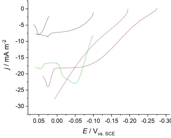
500 μM p-BQ at 24 (blue), 96 (green), and 144 h (red) (run 3) 4446 Figure 19: Cathodic quasi-stationary polarization curves of batch (green), flow (blue) and flow MFC with engineered alginate capsules with 0.15 gL-1 AC (red), 0.5 gL-1 AC (purple)
and 0.15 gL-1 AC with 500 μM p-BQ (cyan) obtained during the first degradation cycle
47 Figure 20: Cathodic quasi-stationary polarization curves for flow MFC with engineered alginate capsules with 0.15 gL-1 AC and 500 μM p-BQ, run 1 (red), run 2 (green) and run 3
(magenta) obtained during the first degradation cycle 48 Figure 21: Cyclic voltammetry of media with no p-BQ (blue), with 500 μM p-BQ (green) and media of the flow-MFC with 0.15 gL-1 AC and 500 μM p-BQ extracted after the third
degradation cycle 49
Figure 22:Cyclic voltammetry of media with no p-BQ (blue) and media of the flow-MFC with 0.15 gL-1 AC and 500 μM p-BQ after the second degradation cycle (black) and after the
third degradation cycle (red) 50
Figure 23: Anodic and cathodic potentials of MFCs in: batch conditions with unmodified capsules (blue), flow conditions with unmodified capsules (orange), flow with 0.15 gL-1 AC
modified capsules (grey), flow with 0.5 gL-1 AC modified capsules (yellow) and flow
viii
Figure 24A: COD (red) and COD removal % (blue) for batch MFCs. COD values refer to the left axis, COD removal % refer to the right axis. Green, yellow, and orange areas indicate the first, second and third degradation cycles, respectively. Three independent replicate experiments were performed, and error bars indicate standard deviation
53 Figure 24B: COD (red ) and COD removal % (blue) for flow MFCs. COD values refer to the left
axis, COD removal % refer to the right axis. Green, yellow, and orange areas indicate the first, second and third degradation cycles, respectively. Three independent replicate experiments were performed, and error bars indicate standard deviation
5354 Figure 24C: COD (red) and COD removal % (blue) for flow MFCs with 0.15 gL-1 AC modified
capsules. COD values refer to the left axis, COD removal % refer to the right axis. Green, yellow, and orange areas indicate the first, second and third degradation cycles, respectively. Three independent replicate experiments were performed, and
error bars indicate standard deviation 5355
Figure 24D: COD (red ) and COD removal % (blue) for flow MFCs with 0.5 gL-1 AC modified
capsules. COD values refer to the left axis, COD removal % refer to the right axis. Green, yellow, and orange areas indicate the first, second and third degradation cycles, respectively. Three independent replicate experiments were performed, and
error bars indicate standard deviation 5356
Figure 24E: COD (red) and COD removal % (blue) for flow MFCs with 0.15 gL-1 AC and 500 μM
p-BQ modified capsules. COD values refer to the left axis, COD removal % refer to the right axis. Green, yellow, and orange areas indicate the first, second and third degradation cycles, respectively. Three independent replicate experiments were performed, and error bars indicate standard deviation 5357 Figure 25A: Cyclic voltammetry of EAGSL-alginate capsule: unmodified (magenta), with 0.5 gL-1
AC (blue); with 500 μM BQ (green) and with both 500 μM BQ and 0.5 gL-1 AC (red)
59 Figure 25B: Cyclic voltammetry of control-alginate capsule: unmodified (magenta), with 0.5 gL-1
AC (blue); with 500 μM BQ (green) and with both 500 μM BQ and 0.5 gL-1 AC (red)
60 Figure 26A: Chronoamperometry of EAGSL-alginate capsule: unmodified (magenta), with
0.5 gL-1 AC (blue); with 500 μM BQ (green) and with both 500 μM BQ and 0.5 gL-1 AC
(red) 61
Figure 26B: Chronoamperometry of control-alginate capsule: unmodified (magenta), with 0.5 gL-1 AC (blue); with 500 μM BQ (green) and with both 500 μM BQ and 0.5 gL-1 AC
(red) 6162
Figure 27A: Cyclic voltammetry of media with 500 μM p-BQ in solution (black) and media of the third run in batch configuration with 0.5 gL-1 AC and 500 μM p-BQ after three days
ix Figure 27B: Cyclic voltammetry of media with no p-BQ in solution (blue), media of the first (black) and third (red) run of batch configuration with 0.5 gL-1 AC and 500 μM p-BQ after
three days 6364
Figure 28: Cyclic voltammetry of media with no p-BQ in solution (black), media of batch configuration with only 500 μM p-BQ modified capsules after three days (red) 65
x
Index of tables
Table 1: Evolution of power densities during three degradation cycles for batch, flow, and flow MFCs with composite capsules (0.15 and 0.5 gL-1 activated carbon) 31 Table 2: Power densities values during three degradation cycles for the triplicates of flow MFCs
xi
List of abbreviations
EAGSL: Electro Active Great Salt Lake EET: Extracellular Electron Transfer MFC: Microbial Fuel Cell
CE: Coulombic Efficiency GSL: Great Salt Lake AC: Activated Carbon P-BQ: Para-Benzoquinone DET: Direct Electron Transfer MET: Mediated Electron Transfer CEM: Cation Exchange Membrane PEM: Proton Exchange Membrane
DCMFC: Double Chamber Microbial Fuel Cell SCMFC: Single Chamber Microbial Fuel Cell RVC: Reticulated Vitreous Carbon
CNTs: Carbon Nanotubes
GAC: Granular Activated Carbon ORR: Oxygen Reduction Reaction DL: Diffusion Layer
PGM: Platinum-Group Metal
PGM-free: Platinum-Group Metal- free PTFE: Poly(tetrafluoroethylene)
xii
WE: Working Electrode CE: Counter Electrode
SCE: Saturated Calomel Electrode SHE: Standard Hydrogen Electrode RE: Reference Electrode
CV: Cyclic Voltammetry CA: Chronoamperometry
xiii
Abstract
Saline and hypersaline wastewater account for a significant amount of the total wastewater generated worldwide. However, due to the inhibiting effect that high salinity plays on the activity of bacterial cells, a cost-effective treatment approach has yet to be developed. Application of halotolerant Salinivibrio sp., named Salinivibrio EAGSL (Electro Active Great Salt Lake), in a flow-microbial fuel cell (MFC) system for saline wastewater treatment and monitoring, is herein investigated in lab-scale devices. Flow resembles the on-field application of the technology, but it introduces several parameters that can potentially reduce bio-electrochemical and degradation performance. Engineering of alginate capsules, modified with activated carbon, in order to enhance their conductivity, and further modified with para-benzoquinone, to enhance electron transfer, was investigated as a possible solution to restore MFC performance. A higher maximum power density, as well as improved organic removal, was achieved with modification of alginate capsules. However, the high variability of values found in this study suggests that further investigations must be done before on field application of this technology becomes feasible.
Keywords: flow microbial fuel cell; alginate capsules engineering; EAGSL; hypersaline
solution; wastewater treatment; chemical oxygen demand monitoring.
Le acque reflue saline e iper-saline rappresentano una quantità significativa di quelle mondiali. Tuttavia, a causa dell'effetto di inibizione che l'elevata salinità svolge sull'attività delle cellule batteriche, non è ancora stato sviluppato un approccio di decontaminazione efficace e a basso costo. L'applicazione del batterio Salinivibrio EAGSL in un sistema a celle a combustibile microbiche (MFC) per il trattamento e il monitoraggio delle acque reflue saline, è qui esaminata in dispositivi di laboratorio. L’introduzione di un flusso è necessaria per trasportare questa tecnologia su scala industriale, ma introduce diversi parametri che possono potenzialmente ridurre le prestazioni bio-elettrochimiche e di degradazione. La modifica delle capsule di alginato con carbone attivo, al fine di migliorare la loro conduttività e con para-benzochinone, per migliorare il trasferimento di elettroni, è stata studiata come possibile soluzione per ripristinare le prestazioni delle celle (MFC). Una maggiore densità di potenza massima, nonché una migliore rimozione organica, è stata ottenuta con la modifica delle capsule di alginato. Tuttavia, l'elevata variabilità dei valori rilevati in questo studio ci suggerisce che devono essere condotte ulteriori indagini prima che l'applicazione sul campo di questa tecnologia diventi possibile ed efficace.
1
1. Introduction
The scarcity of fresh water characterizes approximately 80% of the human population[1]. As a consequence, in a few cities such as Hong Kong, toilets are flushed with seawater, generating saline sewage. With increasing water scarcity, expected in the course of the century, such practice will become more common, resulting in the release of even more saline wastewater[2]. Moreover, expansion of food processing, textile, leather and petroleum industries has led to an increase in hypersaline wastewater generation[3], with dissolved inorganic salt content greater than 3.5% w/v, which already accounts for approximately 5% of effluents worldwide[4] (approximately 100 trillion liters yearly). Additionally, climate change repercussions, such as sea level rise, extreme weather events, coastal erosion, changing precipitation patterns, warmer temperatures, and the potential for increased freshwater demand, could all rise the risks of saltwater intrusion especially in coastal areas. Saltwater intrusion refers to the process by which sea water moves far enough inland that it “intrudes” into aquifers and affects fresh coastal groundwater systems such as wells and bioremediation plants, thus mixing with the local freshwater supply[5]. Therefore, increasing generation of saline and hypersaline wastewater has intensified interest in developing new water treatment techniques capable of operating under high salinity conditions[6].
Generally, biological processes are applied to mineralize the organic contaminants in wastewater to less harmful and non-hazardous substances. However, classical aerobic biological treatments are not suitable for the treatment of hypersaline solutions due to inhibition of bacterial cell activity, resulting in the inactivation of the biological processes[7]. Thus, expensive and energy intensive pre-treatments, like thermal evaporation and dilution, or other extremely energy requiring physico-chemical treatments, such as membrane filtration and ion exchange techniques, are utilized to treat saline wastewaters[8]. Moreover, solutions characterized by high salinity are responsible for severe fouling in pipes and industrial plants. These issues make the treatment of hypersaline wastewater a highly complex task, especially in developing countries where the risk of contaminant release into the environment is high due to limited economical capabilities[9].
The possibility to use microorganisms to degrade organic wastes in hypersaline environments is then of rising interest, since this would prevent expensive decontamination approaches or contamination tout court of the environment. The combination of microbial metabolism with an electrochemical system has been investigated for the self-sustained treatment of wastewater. Specifically, bacteria capable
2
to exchange electrons with an electrode surface, a process defined as extracellular electron transfer (EET), can be applied in a microbial fuel cell to enhance the removal of organic contaminants[8]. Microbial fuel cells offer the possibility of harvesting electricity from organic wastes and renewable biomasses. MFCs are attractive sources of energy because they are ‘carbon-neutral’, that is the oxidation of the organic matter only releases recently fixed carbon back into the atmosphere. Another advantage is that microbial fuel cells can be operated at room temperature and could potentially be designed to function at any temperature at which microbial life is possible[10]. Therefore, microbial fuel cells might be particularly attractive power sources in remote locations and regions of developing countries, especially when seeded with halotolerant bacteria to treat hypersaline solutions[11].
Application of halotolerant bacteria, capable of tolerating moderate to high salinity, to the treatment of saline wastewater has been explored, with promising results for bioremediation of oil spills in salt marshes[2–12–13]. Inspired by the successful application of halotolerant bacteria for saline wastewater treatment, research efforts have been focused to unveil their bio-electrocatalytic properties for application in MFCs, [6– 8] which were successfully operated with these organisms for solution with salinities higher than 100 gL-1. The interest in MFCs is also due to the high theoretical efficiency of
energy generation (+80%) that has been reported[14]. However, the overall energy efficiency of the devices is less than the theoretical one because the majority of organisms cannot use complex substrates, thus relying on low-molecular-weight organic acids that are provided by fermenting bacteria[14]. Power densities and coulombic efficiencies (CE) are even lower for hypersaline solutions, mostly due to the additional energy required by bacterial cells to balance the osmotic pressure in saline solutions[15]. Moreover, detailed information on EET processes remains limited, particularly for halotolerant microorganisms. Their better understanding could strongly enhance bio-electrocatalytic performance, making the application of MFCs for saline solution treatment more competitive[8]. Although MFCs are characterized by a limited power output, particularly in hypersaline conditions, one of their important features is that they perform a self-powered organic removal process and could be used as a biosensing tool to monitor the processes on-line, tracking changes in the characteristic electrochemical parameters of the MFCs[16].
The Great Salt Lake (GSL) in Utah (USA) is a hypersaline lake where NaCl constitute 86% of the total salt and represents one of the world's most extreme environments for biological entities. The salinity of the lake can range between 50 and 280 gL-1 depending
on the seasons and the location[7]. A strain of halotolerant Salinivibrio sp. was isolated from the GSL, named Salinivibrio EAGSL, and its potential application in batch MFC for organic removal was showed[17]. Furthermore, encapsulation of bacterial cells into alginate capsules allowed stable performance of the device over long-term operation (> 5 months), and the possible correlation between current production and concentration of organic substrates was reported[13], opening for the development of self-powered hypersaline biosensors. Several aspects require further elucidation in order to scale up the technology for in field application, where most of the biological treatment plants operate in continuous mode. Specifically, cost-effective and robust electrode materials
3
will be required, and the device will have to withstand high load of solutions to be treated daily. Accordingly, operation of the bio-electrochemical systems in continuous flow, rather than batch mode, is essential. Flow operation limits the contact of organic compounds in solution with bacterial cells, potentially decreasing bio-electrochemical performance. With this issue in mind, the aim is to investigate the effect of flowing conditions on bio-electrocatalysis and organic removal performance. Herein, a flow microbial fuel cells operated at a total salt content higher than 100 gL-1 with bacterial cells
entrapped in alginate capsules for enhanced stability, and to avoid loss of bacteria due to the applied flow, was investigated. Moreover, alginate capsules modification with activated carbon (AC) and para-benzoquinone (p-BQ) was taken in consideration. The introduction of the flow strongly affected bio-electrocatalytic performance; however, the negative effects of flow operation were overcome by careful engineering of bacteria cell entrapment.
4
2. State of art
2.1 Microbial fuel cell’s functioning
MFCs are electrochemical fuel cells in which the organic matter found in the wastewater (substrate) is oxidized by microorganisms[18]. These devices mainly consist of an anode, which accepts electrons from the microbial culture, and a cathode, which transfers electrons to a final electron acceptor[10]. MFCs can directly convert chemical energy from an organic substrate to electrical energy through a cascade of redox reactions[19], in which the oxidation and the reduction processes are separated, and the microorganisms are forced to use the electrodes as intermediate[16]. More precisely, the bacteria act as catalysts to oxidize organic and inorganic matter generating electrical current. At the anode, bacteria oxidize substrates and generate electrons and protons, producing carbon dioxide as an oxidation product. However, no net carbon emission is achieved as the renewable organic substrate is originated from photosynthesis process in atmosphere[20]. At the cathode, electrons, protons and oxygen combine to form water (fig.1).
5
2.2 Electron transfer between substrate, electrode and
microorganisms
Organic compounds must be oxidized to carbon dioxide in order to efficiently extract the available electrons and convert them into current[21]. More precisely, the energy needed to sustain their life, gained by the oxidation, is the Gibbs free energy of their oxidation (𝛥𝐺𝑜𝑥). The more positive the redox potential of a terminal electron acceptor the higher
the energy gain for an organism [14].
Two major metabolic pathways can be distinguished: respiration and fermentation. During respiratory substrate oxidation, the liberated electrons are transferred via a redox cascade, here called the respiratory chain, and are finally transferred to an externally available terminal electron acceptor. Aerobic respiration is the path with the highest energy gain, but it is limited to environments in which oxygen is available. An example is glucose oxidation:
C6H12O6+ 6O2 → 6H2O + 6CO2 ΔGox= −2895 kJ mol⁄ (eq. 1)
Under anoxic conditions, specialized facultative or obligate anaerobes utilize other, inorganic or organic, exogenous compounds as terminal acceptors for an anaerobic respiration like nitrate, sulfate, carbon dioxide and metal ions (Fe3+). Due to the less
positive redox potentials of these oxidants, the energy gain for the organisms are usually considerably lower compared to aerobic respiration[14].
In the absence of exogenous oxidants, many microorganisms perform fermentation, a biological form of disproportionation, in which part of the organic substrate acts as electron acceptor and become reduced, while another part is oxidized (eq.2.1 and eq.2.2). A large variety of fermentative and photo-heterotrophic processes result in the production of energy-rich reduced metabolites such as hydrogen, ethanol or formate [14].
C6H12O6 → C3H7COOH + 2CO2+ 2H2 ΔGox= −225 kJ mol⁄ (eq. 2.1)
C6H12O6 + 2H2O → 2CH3COOH + 2CO2+ 4H2 ΔGox= −206 kJ mol⁄ (eq.2.2)
However, fermentation alone cannot be a strategy for efficiently converting organic matter to electricity because most of the electrons available in the organics remain in fermentation products that do not readily react with electrodes[10].
After the decomposition of carbon sources catalyzed by bacteria[19], the generated intracellular electrons must be transferred to the anode. Since electrodes are solid entities that cannot penetrate the bacterial cells, a major requirement is that electrons are to be transferred from the inside of the microbial cell membrane to its outside either via the physical transfer of reduced compounds, or via electron hopping across the membrane,
6
using membrane bound redox enzymes[14]. Two major mechanisms can be defined: direct electron transfer (DET), and mediated electron transfer (MET).
Figure 2: Schematic of the electron transfer mechanisms from the microorganism to the anode
2.2.1 Direct electron transfer
DET takes place through membrane bound cell organelles or conductive nanowires with no diffusional redox species being involved in the electron transfer from the cell[19]. The DET requires that the microorganisms possess membrane bound electron transport protein relays, that transfer electrons outside of the cell, terminating in an outer membrane redox protein that allows the electron transfer to an external and solid electron acceptor (MFC anode)[14].
It was proposed that electrons might be directly transferred from the cell to the electrode through outer-membrane c-type cytochromes[10]. Studies have showed that a few electrochemically active bacteria possess efficient DET mechanism (e.g., Geobacter,
Rhodoferax and Shewanella)[10]. The major limitation of this process is that the bacteria
must adhere to the anode, by forming a biofilm, for the electron transfer, and only bacterial populations in the first layer of biofilm are involved in the DET[19].
Another possible form of DET is through conductive pili (nanowire) formed on the bacterial cell surface connected to the cytochrome which can transfer/conduct electrons from internal layers of biofilm to the anode[22]. Organisms like Geobacter and
Shewanella are capable of producing electrically conductive nanowires[23]. This may
allow the formation of thick electroactive biofilms leading to increased anode performance[19].
7
Attachment of microorganisms, that are not effective in current production, may be especially problematic when the conversion efficiency of organics into electricity is low[24]. Under such circumstances many, if not most, of the microorganisms attached to the anode may use the anode as a convenient surface for attachment and biofilm formation, carrying out forms of metabolism other than electron transfer to the anode. Furthermore, in the presence of complex organic substrates, it is necessary that part of the microbial community has microorganisms that transform such compounds into more simple substrates[21].
2.2.2 Mediated electron transfer
Mediated electron transfer is based on redox species that can be present, dissolved in solution or immobilized in a polymer backbone. It takes place through the redox shuttles that mediate the electron flow from the bacterial metabolism towards the electrode. The outer layers of most microbial species are composed of non-conductive lipid membrane, such as peptidoglycans and lipopolysaccharides, which hinder the direct electron transfer to the anode. Mediators in oxidized state can reduce in presence of electrons within the membrane. The mediators then move across the membrane and release the electrons to anode, becoming oxidized again[19]. MET occurs either by the addition of artificial mediators or by secretion of soluble mediators such as primary and secondary metabolites from bacterial metabolism[25].
Artificial mediators offer the possibility for microorganisms to generate reduced products that are more electrochemically active than most fermentation products. These electron shuttles are typically capable of crossing cell membranes, accepting electrons from one or more electron carriers within the cell, exiting the cell in the reduced form and then transferring electrons onto the electrode surface[26]. Common electron shuttles include phenazines, phenothiazines, phenoxazines and quinones. A major objection to the use of artificial electron shuttles, in the development of practical microbial fuel cells, is that most applications will probably require continuous or semi-continuous input of the substances in open systems[10]. This will require continual addition of the electron shuttle, which would increase operational cost, besides being environmentally questionable[14].
In some instances, microorganisms might produce their own mediators to promote EET[10]. Usually, the release of low molecular weight electron shuttling compounds is through secondary metabolic pathways. The redox shuttles released by one organism can be utilized by other bacterial population[19]; therefore, one molecule can thus serve for thousands of redox cycles.. However, the creation of these molecules is probably energetically expensive, leading to additional biological losses[14]. In general, microorganisms that produce electron shuttles in open environments have the disadvantage of rapidly losing the mediator from the site of release. Another significant factor limiting the effectiveness of electricity production, is due the incomplete oxidation of the organic substances by these microorganisms[10].
8
In contrast to the secondary metabolites, the production of reduced primary metabolites is closely associated with the oxidative substrate degradation. Usually, these mediators are produced with anaerobic respiration or fermentation[14].
As an additional mediation approach, the immobilization of redox mediators on the backbone of polymers has been investigated for the development of redox polymers. The advantage of this mediating system is that the mediators are no longer freely diffusing in solution. However, their capability to reach the active redox sites in the bacterial cells might be compromised, due to the confinement on the polymer structure. Examples of this mediating approach have been recently reported[27], and careful engineering of the polymer immobilization was required to establish successful EET[28].
2.3 Microbial fuel cell’s configurations
MFCs have mainly two different configurations: double-chamber MFC (DCMFC), and single-chamber MFC (SCMFC).
2.3.1 Double-chamber microbial fuel cell
A DCMFC (fig.3) consists of two compartments, anodic and cathodic chambers, normally separated by a cation exchange membrane (CEM), such as Nafion and Ultrex, or a plain salt bridge, to allow protons to move across to the cathode compartment while blocking the diffusion of oxygen into the anode compartment[20].
In general, this configuration exhibits a high electricity generation and wastewater treatment efficiency. This is attributed to lower cathode overpotential and higher coulombic efficiency. In fact, the proton exchange membrane (PEM) reduces oxygen crossover to the anode and leads to higher CEs[29]. However, the pH imbalance between the anode and cathode chamber, which is caused by the limited proton transfer across the PEM, results in the anode chamber acidification, which leads to the inhibition of microbial activity and, thus, a deteriorated performance[30]. In a double chamber microbial fuel cell, the anode chamber acidification can be alleviated by adding bases or buffers. However, these approaches increase the operational energetic and material demands[29].
9 Figure 3 [31]: Schematic of a double chamber microbial fuel cell
2.3.1.1 Proton exchange membrane
The ion-exchange-membrane is in principle not an essential requirement, provided that the anode and cathode are either dissimilar, which is the equivalent to electrochemical separation, or they are at a certain distance, so that short-circuit can be avoided[32]. Proton-exchange membrane allows proton migration from the anode to the cathode. PEMs exhibit several advantages over liquid or solid inorganic electrolytes, such as high proton conductivity, good chemical, thermal and mechanical properties[33].
The main features and purposes of membranes in MFCs are to[10–34]: 1) separate the anodic chamber from the cathodic one (Fig. 3);
2) restrict oxygen diffusion from the cathode chamber to the anode chamber, while allowing protons that are released from organic matter metabolism, or oxidation of reduced metabolic products, to move from the anode to the cathode;
3) increase the coulombic efficiency by ensuring optimal operational conditions in each chamber;
4) ensure an efficient and sustainable operation over time.
The most commonly used PEM is Nafion due to its highly selective permeability of protons. Despite Nafion being expensive (membranes can cost up to $2000 m-2 [35])it is
10
membranes has been carried out in recent years: ultrafiltration and microfiltration membranes, sulphonated polyether ether ketone membrane, anion and cation exchange membranes, bipolar membranes, and forward osmosis membranes[20]. In order to reduce the impact of membrane costs, other options have been explored, such as membrane-less MFCs and new alternative materials. In principle, any type of porous material, with sufficient strength, chemical inertness and durability could be employed as a PEM. Membrane materials reported in literature range from microporous filtration membranes tophotocopy paper, ceramics or even shopping bags[32].
2.3.2 Single-chamber microbial fuel cell
A SCMFC consists of a single compartment in which cathode and anode are placed with no separating membrane. The cathode is a so called “air-breathing cathode”, in which one side is directly in contact with the solution and the other side is exposed to atmospheric oxygen. This configuration is an easier and more cost effective design due to the absence of a PEM and the use of oxygen in air as electron acceptor[29]. In addition to lower cost, the single-chamber MFC benefits from reduced internal resistance, enabling improved performance[36].
The main disadvantages are the decreased CE that results from oxygen diffusing from cathode to anode[37]and a low power density caused by the thermodynamic and kinetic constraints of oxygen reduction reaction (ORR) at the cathode[29].
11
2.4 Electrode material
Over the past decade, a variety of electrodes have been extensively explored for MFCs. With different electrode materials the impact on microbial attachment, electron transfer, electrode resistance and the rate of electrode surface reaction varies[38]. Therefore, the material directly influences the performance as well as the cost for MFC development. Criteria for selecting materials and configurations for anode and cathode are different. The anode needs to provide a suitable environment for microorganisms to attach and collect electrons, while the cathode has to facilitate the occurrence of electron accepting reactions (catalytic ability)[39].
Although the criteria are different, in general both should possess the following properties[38]:
1) Good electrical conductivity. Electrons released from microorganisms must travel along an external circuit after passing through the anode.
2) Low interfacial impedance to facilitate the electron transfer[18].
3) Chemical stability and durability. The reducing and oxidizing environment in an MFC may lead to the swelling and decomposition of the materials. Therefore, the material for electrodes should be durable as well as stable in acidic and basic environments[18]. 4) Large surface area. Enlarging the surface area of the electrode increases the total
reaction rate, hence increases the amount of collected current[39].
5) Porosity. Porosity will decrease the electrical conductivity of the material but will enhance the surface area and offer more sites for the bacteria to grow in, improving biofilm formation and electron donation to the electrode surface[18].
6) Low Cost. The cost of the electrode material influences the capital cost of the MFC to a large extent[18].
2.4.1 Anode material
Easy and effective colonization of the biocatalyst over the electrode surfaces and increased electron transfer are the two major criteria for the anode selection[19]. Common materials include a large variety of carbon materials and several metal materials.
12
Figure 5[32]: Examples of common materials for anodes
2.4.1.1 Carbon based anodes
Carbon materials are the most widely used materials for MFC anodes because of their good biocompatibility, good chemical stability, high conductivity, and relatively low cost[40].
Due to its excellent electrical conductivity and chemical stability, the graphite rod has become one of the most commonly used electrodes. However, the application of the graphite rod is limited because of its low surface area for microorganism adsorption[38]. Carbon paper is very thin and relatively stiff but slightly brittle. Graphite plates or sheets have higher strength than carbon paper and a relatively uniform surface, both of which facilitate the quantitative measurement of biomass per unit of surface area. Carbon cloth is more flexible and much more porous, it has high surface area and relatively high porosity allowing more surface area for bacterial growth[40]. It also has high electrical conductivity, as well as good mechanical strength, in forming more complex 3D
13
structures. The negative aspect is related to the cost that is generally quite high[32] (ca. $ 1000 m-2)[41].
An inexpensive carbon mesh material ($ 10–40 m-2) could be used as a substantially less
expensive alternative to carbon paper and carbon cloth. In fact, treated carbon mesh anodes showed improved power densities comparable to those of much more expensive carbon cloth[42]. The main problem is related with the low mechanical strength that could lead to low durability under high flow conditions. Carbon mesh can be also folded to obtain a 3-Delectrode, but its porosity is low.
Carbon veil is as well a very cost-effective material with relatively high electrical conductivity and high porosity. A single layer is quite fragile but since the material is versatile, it can be folded to form a robust and porous 3-D electrode[32].
Similar to carbon veil, carbon felt shows high porosity and high electrical conductivity; the cost is relatively low and the mechanical strength is high depending on the thickness of the material[32].
Compared with the carbon materials described above, reticulated vitreous carbon (RVC) is less frequently used in MFCs studies due to its large resistance[38]. However, it possesses unique characteristics being very conductive and having great porosity allowing the biofilm to penetrate through the entire structure and colonize the entire electrode. Unfortunately, the material is quite fragile and very expensive[43].
Three-dimensional electrode materials increase the electrode surface area, and this is an effective way to improve the performance of MFCs. However, in a conventional two-dimensional electrode system, the increase in the electrode size is accompanied by an increase in the reactor volume and the infrastructure costs[38].
Graphite brushes are made of fibers wounded around one or more conductive corrosion-resistant metal wires (titanium). This anode is an ideal electrode that achieves high surface area, with an optimal area to volume ratio, high porosities[44] and high electrical conductivity guaranteed by the central titanium metal that at the same time increases the material cost[32]. It has also to be said that the use of materials, such as carbon cloth or graphite granules, presents substantial difficulties for scale up, like clogging and low structural strength (that with scaling up needs to be high to support bigger biofilms). The brush architecture should be capable of being scaled up and used in larger-size reactors[43].
Carbon nanotubes (CNTs) have become one of the electrode materials with the most potential because of their unique electrical conductivity, chemical stability, biocompatibility, high specific area[18], high mechanical strength and ductility[38], and also catalytic properties, resulting in strong cell adhesion and growth[45], as well as in excellent charge transfer characteristics due to p–p stacking between the carbon atoms of graphite and the pili (a cellular outgrowth) of microorganisms[18]. However, the high cost of CNTs , which was reported to be $80–100 m-2, is one of the major factors that limits
this application[38]. For more cost effective anodes based on CNTs, a thin layer deposition of the latter on recyclable polymeric support has been recently reported, decreasing the fabrication cost while maintaining biocompatibility[46].
Granular activated carbon (GAC) is also used as anode electrode due to its biocompatibility and low cost[47]. The material is very porous and consequently the electrical conductivity remains quite low. Due to these characteristics, GAC is used mainly
14
as a packing material rather than stand-alone anode. To increase conductivity, GAC has to be packed and this might lead to possible clogging in a flow-through MFC configuration. The overall surface area is quite high but the surface area available for bacteria interaction is rather low due to its nanometric scale.
Carbonized cardboard is also a very interesting 3-D material composed by a single wall corrugated cardboard from recycled paper. The material is very low-cost, has high electrical conductivity and high porosity[48].
2.4.1.2 Metal and metal oxide anodes
Metal materials are much more conductive than carbon materials, but their application is complicated due to the non-corrosive requirement and the smooth surface that does not facilitate the adhesion of bacteria[40]. So far, only stainless steel and titanium qualified as relative common base materials for anodes[49]. Nickel can be used as a replacement of graphite, especially in large scale MFC operations[50]. Gold anodes have also been used in several studies[51]. In general, all metal anodes where investigated in lab-scale and remain not widely used. Copper, aluminum and brass were reported as non-suitable materials for anodes due to their solubility, easy oxidizing properties and their toxicity (mostly for copper) towards the biocatalyst[50].
2.4.1.3 Composite electrodes
The performance of metal–graphite composite anodes has been tested in several studies. Recently, it was reported that CNTs incorporated with a conductive polymer can lead to a synergistic effect[52]. Also, CNTs deposition over carbon paper increases the power density[18]. However, further investigations are required before the widespread application of composite electrodes[40].
2.4.2 Surface improvements
To improve bacterial adhesion and electron transfer, electrode surface modification has become a new topic of interest. The composition, roughness and charge of a surface, as well as its hydrophobic or hydrophilic and lipophobic or lipophilic nature, can each influence biofilm formation. Furthermore, the structure of surface functional groups can strongly influence electron transfer rates at biofilm/electrode interfaces and can interfere with the natural EET processes[53]. These modifications include surface treatments with chemical and/or physical methods, addition of highly conductive or electroactive coatings[40] and other methods:
15
a) surface charge, with positive charges usually preferred[54], by:
i) Acidic treatment. When the electrode surface is treated with concentrated inorganic acids, it results in the protonation of functional groups over the electrode surface, increasing the number of positive charges over the surface of the electrode. Furthermore, acidic treatment leads to creation of cracks (roughness) in the material which also enhance the performance[18].
ii) Heat treatment. Heat treated anode surfaces may produce less contaminants that interfere with charge transfer from bacteria to anode surface[40]. The heating method could modify the electrochemical activity by increasing the electrochemically active surface area and decreasing the O/C ratio[38].
b) Hydrophilicity/hydrophobicity. With hydrophilic surface preferred during bacteria attachment[55].
c) Oxygen or nitrogen functional groups that facilitate bacteria/surface interaction[56] by:
i) Ammonia treatment. It increases the adhesion between bacteria and electrode surface[57]. This method is suitable for many carbon electrode materials including carbon cloth and carbon paper, and it has been regarded as one of the most effective ways to improve electrode performance[42–57]. This occurs mainly because the treated carbon cloth can improve the amount of surface charge and thus is more conductive to microbial electron transport[38].
ii) Electrochemical oxidation treatment. It creates new functional groups over the surface. The bacteria form peptide bonds with electrodes and therefore create a pathway for the effective transfer of electrons[18].
2) Controlling the surface morphology at the nano/micro-scale[56]. The tendency is to move from a flat 2-D surface towards a 3-D. This transition implies also the possibility of facing limitations due to diffusion transport phenomena of both products and reactants, and relative pH gradients[32].
3) Using coatings: aside from surface treatments, other approaches have been taken to increase anode performance via the addition of a surface coating. The surface coating materials currently reported include carbon nanotubes (CNTs), conductive polymers, metals, and composites of these materials[40].
In certain cases, several modified methods are used concurrently to achieve a better treatment effect, for example, by combining the heat and acid treatments the power production could improve [38].
2.4.3 Cathode materials
Similar to the anode, the cathode also has significant impact on power generation efficiency and it should have high redox potential and easily capture protons[38].In fact, at the cathode, electrons, protons and oxygen (due to its omnipresence and its high oxidation potential, oxygen is the preferred oxidant in microbial fuel cells[58]) combine to form water or hydroxide depending on the oxygen reduction reaction pathway[18]. The acidic pathway implies the pH and it has the intermediate production of H2O2 (involving
16
2𝑒−) with the final product being H
2O (involving additional 2𝑒− (i.e. a total of 4𝑒−
involved)[32].
In the presence of an alkaline aqueous electrolyte, the reaction mechanism reduces oxygen to hydroxyl ions following a pathway which involves a number of electrons between 2 and 4 depending on the catalyst used[59]:
O2 + 2H2O2 + 4e− → 4OH− 0.401 V vs. SHE (eq. 3.1)
O2 +H2O + 2e− → HO2− + OH− -0.065 V vs. SHE (eq. 3.2)
HO2− + H2O + 2e− → 3OH− 0.867 V vs. SHE (eq.3.3)
2HO2− → 2OH− +O
2 (eq.3.4)
A catalyst of choice would reduce the oxygen following a 4e−pathway either through a
one-step reaction (eq. 3.1) or a two-step reaction (eq. 3.2 and eq. 3.3). Other catalysts reduce oxygen to hydrogen peroxide (eq. 3.2), which then chemically decomposes (eq. 3.4) leading to a 2e− process[60]. Although it is known that Pt and Pt-alloys can catalyze
the direct ORR (4e−), they also increase the total cost of the MFCs and suffer from fast
poisoning from sulfides in wastewater[61]. As a consequence, the investigation on alternative Pt-free catalysts has been thorough[60].
Most of the materials used as an anode can be used as a cathode, however in addition a robust MFC cathode should have: high mechanical strength, catalytic properties and high electronic and ionic conductivity[18].
A typical MFC cathode has three layers: i) gas diffusion layer (DL), ii) conducting support material, and iii) catalyst. Oxygen reduction reaction kinetics are very slow, especially under MFC operating conditions (i.e. ambient temperature, atmospheric pressure and neutral pH), and thus ORR catalysts with high performance in terms of catalytic efficiency and durability are needed for air-breathing cathode preparations[62].
Catalysts used in MFCs can be grouped in three main categories according to the function of the presence/absence of platinum and other metals. These categories are[32]:
1) Platinum-based (PGM-based) with a 4e− transfer mechanism: these are supposed to
reduce the cathodic reaction activation energy and increase the reaction rate[38]; however some limitations with Pt include pH sensitivity, sulfide poisoning and non-sustainability[18]. Pt is an expensive metal, and this limits its practical application. 2) Carbon-based (metal-free) with a 2e− transfer mechanism: chemically modified
carbon-based materials including carbon nanotubes, graphene and graphite foam can be used as catalyst for ORR. ORR can proceed to four electron pathway using a nitrogen incorporated catalysts[63]. Nitrogen doped graphene nanosheets have shown high catalytic activity, stability and onset potential[18].
3) Platinum-group metal-free (PGM-free) with a more complex electron transfer mechanism (2e− or 2 x 2e− or 4e−): phthalocyanine can be used as a catalyst, taking
17
the advantage of the p–p interaction between the metal and carbon of the aromatic ring, leading to rapid electron transfer[64].
4) Other: manganese dioxide (MnO2) has been used as a shuttling mechanism for oxygen
reduction showing catalytic properties quite close to platinum catalyst. Palladium, a Pt-like transition metal, is being tested for use as a cathode due to its excellent catalytic properties. Lead oxide is also used as an alternative catalyst for MFC cathodes with a cost 8 times lower than Pt–carbon electrode[65].
There are mainly three different kinds of cathodes:
1) Aqueous air–cathodes: made of conductive supporting materials, such as carbon paper, carbon cloth, and platinum mesh, coated with a catalyst/binder layer[66]. The performance of aqueous air–cathodes is limited by low amount of dissolved oxygen in solution[40].
2) Air–cathodes: consist of a diffusion layer (exposed to air), a conductive supporting material, and a catalyst/binder layer (exposed to water). Materials are also like anode’s materials (carbon paper and carbon cloth) with stainless steels as the supporting material. Binders such as perfluoro sulfonic acid (Nafion) and poly(tetrafluoroethylene) (PTFE) are commonly used. To avoid high oxygen fluxes from the outside to the inside of the reactor, as well as water losses through the air–cathode, a hydrophobic coating layer (usually called diffusion layer) is needed on the air facing side of the cathode in a single chamber configuration[40]. There are several drawbacks with current catalysts for air-cathode preparation, including high cost and poor durability, which are still bottle-necks for large-scale application of MFCs in practical wastewater treatment[62].
3) Biocathodes: cathodes that use the microorganisms as catalyst. The biofilm formed over the cathode catalyzes the reduction reaction[67]. They have the important advantage of relatively low cost, good stability and multiple functions for wastewater treatment and biosynthesis. The same materials are often used for the biocathode and anode in MFCs. The surface characteristics and surface area available for bacteria are two main factors that affect the biomass on bio-cathodes and their performance[40]. Biocathodes can be categorized as aerobic or anaerobic. In aerobic biocathodes, oxygen is a terminal electron acceptor and hydrogen peroxide is an intermediate. Transition metals such as iron and manganese act as electron mediators between the electrode and oxygen. In anaerobic biocathodes, nitrates and sulfates can be terminal electron acceptors. In addition, an anaerobic biocathode has the advantage of preventing the loss of electrons through oxygen, which may diffuse to the anode and microorganisms at the cathode, and can be used to produce chemicals such as methane, ethanol and formic acid[18].
For wastewater treatments, single-chamber MFCs assembled with bio-anodes and air-cathodes are believed to be one of the most practical configurations because they can be developed as long-term and continuously operated treating systems by passively using air in air-breathing cathodes[68].
18
2.5. Sulfate reducing bacteria[69]
Halotolerant acetate-oxidizing sulfate-reducing bacteria (SRB) can be isolated from sediments of the Great Salt Lake, Utah. This type of bacteria grows in the presence of 0.5 to 13% NaCl in defined medium supplemented with acetate, sulfate and vitamins (yeast extract was found to considerably enhance the cell yield). Optimum growth occurs at 1 to 2 % NaCl. The highest growth rates between pH 6.2 and 7.4 and an optimum temperature at 33°C, with no growth below pH 6.2 or 7.0 °C or above pH 8.1 or 38 °C[70]. SRB usually have an electroactive nature with the ability to perform extracellular electron transfer[71]. SRB enriched MFCs can be cost-effective due to moderate operational condition, low sludge production, and high electric efficiency[21]. SRB also can remove heavy metals due to the formation of highly insoluble precipitates with biogenic sulfide: first, SRB oxidized the lactate and generated hydrogen sulfide and bicarbonate ion under anaerobic conditions. Second, biologically produced hydrogen sulfide reacts with dissolved heavy metals such as Cu to form insoluble metal sulfide precipitates[72]: CH3CHOHCOOH + SO42− → 2CH3COOH + H2S + 2HCO3 (eq. 4.1)
CH3COOH + SO42− → H2S + 2HCO3 (eq. 4.2)
CH3CHOHCOOH + 3SO42− → 3H2S + 6HCO3 (eq. 4.3)
M2++ H2S → MS(s)+ 2H+ (eq. 4.4)
where M2+= metal, such as Cu2+ in this case.
It is important to mention here that valuable metals and elemental sulfur from biologically precipitated metal sulfide can be recovered and recycled in downstream processes[73].
2.6 Background of previous works
2.6.1 Bacteria isolation and characterization
Due to the low conductivity of solutions with no or limited salt content, having higher salinity could be in principal beneficial to the performance of MFC. Miyahara et al. showed that an increase in performance was obtained when the salinity is increased up to 0.1 M NaCl (5.8 gL-1). However, the performance decreased for concentrations higher
19
than 0.3 M (17.5 gL-1)[74]. Therefore, the application of MFCs under hypersaline
conditions is of primary interest, as wastewaters with a high salinity content cannot be treated in normal biodegradation plants. This is due to the imbalance of salt concentration inside the cellular membrane of a bacterial cells and the external solution, that causes an osmotic pressure. Thus, when bacterial cells are in solution characterized by high salinity concentrations, they can suffer dehydration, where water that exits the cellular membrane leads to cell death[74]. Supplying saline wastewater in a biological treatment plant based on activated sludge has been reported to provoke inhibition of up to 84% of the decontamination process[75]. Recently, it has been demonstrated that halotolerant bacteria can be applied in MFCs to perform the remediation of contaminated water[46]. Halotolerant bacteria can tolerate high salinities following two main strategies to adapt to high salt content: the “salt in” strategy, and the “compatible solutes accumulation”. In the “salt in strategy” bacterial cells are able to accumulate ions (mainly potassium) to increase the intracellular ion concentration, allowing for the balancing of the osmotic pressure[76]. In the “compatible solutes accumulation” strategy, bacterial cells can adapt to increased osmotic stress by accumulating compatible solutes. These compounds are defined as small, soluble, organic molecules that can be inside the cellular membrane in high concentrations without affecting the normal cellular metabolism[76]. For this research a new wild-type strain of Salinivibrio sp. allowed the self-sustained treatment of hypersaline solutions. A mixed consortium of halotolerant bacteria isolated from the Great Salt Lake was used, and a bacterial strain was isolated from water samples of the GSL and designated as Salinivibrio sp. strain EAGSL. The bacterial sample was grown aerobically on SRB agar, and colonies were observed under light microscopy. Colonies of the EAGSL strain appeared white or cream colored, raised, and circular in shape with entire edges. The bacterial cell was identified as a Gram-negative, curved rod, motile, facultative anaerobic, and halotolerant bacterium for which significant growth was observed in the presence of 100 gL-1 of NaCl. Sequence analysis indicated that isolated
EAGSL belonged to Salinivibrio sp.. The strain was found to be electrogenic, or electrochemically active, by establishing a successful extracellular electron transfer with carbon anodes both in the absence and presence of exogenous redox mediators [9].
2.6.2 Alginate encapsulation[9]
Alginate is an extremely abundant biopolymer, derived from seaweed[77]. The interest in investigating the possible application of alginate for bacterial cells entrapment was motivated by scanning electrode microscopy (SEM) performed on the electrodes of MFCs operated with unmodified anodes. Such analysis provided evidence that the colonization of anode and cathode surfaces was limited and not uniform. Immobilization of bacterial cells in alginate capsules enables high cell density and increases the stability of bacterial communities[77] by limiting changes in the surrounding environment (i.e., drastic change in substrate concentration, solution composition, etc.). Therefore, the entrapment of bacterial cells allows an increased number of bacteria within the proximity of the
20
electrode surface. Moreover, due to the use of suspended capsules, the biofilm development under DET conditions was not required, resulting in an improved current density at startup of the MFCs.
The results showed that, by applying Salinivibrio sp. EAGSL in a single-chamber Pt-free MFC, the self-sustained treatment of hypersaline wastewater could be easily performed, reaching 87 ± 11 % COD removal after five days of operation, the highest value achieved for hypersaline MFC, and a remarkable increase in power output, reaching values approximately eight times higher.
Interestingly, a redox peak was obtained at a potential of approximately -0.26 V vs. saturated calomel electrode and, as no modification was performed on the alginate matrix, the detection of the redox peak suggested that EAGSL cells were able to secrete different endogenous redox mediators able to diffuse through the alginate capsule, facilitating the EET. Additionally, entrapment of bacterial cells enabled constant improvement of bio-electrocatalytic properties to obtain a system capable of long-term operation. The MFCs showed stable electrochemical performance during several months of experimentation (> five months), with no need for maintenance. The controlled environment achieved by EAGSL capsules allowed more reproducible COD removal, and the decrease in COD removal performance over experiments lasting more than five months was limited to 5–10 %, thus maintaining up to 45% removal of the initial COD.
2.6.3 Transition from batch to flow
Scaling-up of MFCs is necessary in order to apply this technology at an industrial scale. Scaling-up of the air-breathing cathode MFC is the most likely configuration for wastewater treatment due to its high-power output, simple structure, and relatively low cost. But additional work needs to be done in understanding the effects for scaling from laboratory MFCs to industrial size ones[37]. When MFCs sizes have been tested at the scale of several liters or more, volumetric power densities generally were less than 35 Wm-3 [78]. This suggests that the main reason for low power densities is a high internal
resistance which can be due to anode and cathode overpotentials, substrate concentration, membrane resistance, and solution resistance[79]. Power densities can be improved by changing the solution composition as well as designing the MFC with high specific surface area while controlling oxygen crossover so that MFCs can be used in practical applications[37].
Another important factor in scaling up is the modification from batch to flow configuration, as the introduction of a flow would alter several important parameters as substrate diffusion, concentration of redox mediators, bacterial cells attachment on the electrode surface, etc.. Accordingly, this study focuses on unveiling the effects of flow operation on the performance of hypersaline microbial fuel cells.
21
3. Materials and methods
From S. J. Robertson, M. Grattieri, J. Behring, M. Bestetti, & S. D. Minteer, Transitioning from batch to flow hypersaline microbial fuel cells. Electrochimica Acta, 317 (2019) 494– 501.
3.1 Bacterial growth
Salinivibrio sp. EAGSL was previously isolated from a mixture of bacterial samples
collected from the Great Salt Lake[9]. Based on the sulfate-reducing metabolism of EAGSL, a sulfate-reducing medium was utilized for cells grow, as previously reported[7– 46]. The final composition, per liter of de-ionized water, is:
- 0.5 g KH2PO4, - 1 g NH4Cl, - 1 g Na2SO4, - 1 g CaCl2, - 1.83 g MgCl2·6H2O, - 1 g yeast extract, - 0.1 g L-ascorbic acid, - 0.013 g sodium thioglycolate, - 6.38 g sodium citrate, - 0.5 g FeSO4·7H2O, - 1.75 g sodium lactate,
- 2 g sodium acetate trihydrate and - 10 % NaCl (100 g)
The salt content was selected based on the typical value commonly found in brines and shale gas production wastewaters[80]. Chemicals were obtained from Sigma-Aldrich, except KH2PO4 and NH4Cl (Macron Chemicals), Na2SO4 and sodium acetate trihydrate
(Fisher Chemicals), and NaCl (VWR Analytical). The pH of the solution was adjusted between 7.5 and 8 by using 10 M NaOH and 6 M HCl. Before bacteria inoculation, the growth medium was sterilized at 121°C for 25 min (Getinge Group Steam Sterilizer).
22
Calcium chloride and iron sulfate were added after sterilization, by filtration through a 0.20 μm filter. Growth of EAGSL was started transferring cells from 0.5 mL glycerol stocks, stored at -80˚C to 7 mL of sterile SRB medium, and incubated at 30°C and 180 rpm for 24 hours. The growth was then transferred in a 250 mL sterile flask, with a ratio of 1:10 v/v of bacterial growth and fresh SRB medium respectively, for a final volume of 70 mL and incubated under the same conditions for 24 hours.
3.2 Preparation and engineering of alginate capsules
The entrapment of EAGSL cells into alginate capsules was performed following a procedure previously reported[9]. Specifically, a 1:1 volume ratio of alginate and bacterial growth was obtained using a solution of 30 gL-1 alginic acid previously sterilized by
boiling. The resulting mixture was dropped into a 30 gL-1calcium chloride solution to
obtain the alginate capsules with approximately 2 ± 1 mm in diameter. The capsules were then washed with deionized water to remove any residuals of calcium chloride.
Modification of the alginate capsules with activated carbon was performed by adding 0.15 gL-1 and 0.5 gL-1 of AC to the alginic acid solution prior the sterilization step
performed at boiling temperature (fig 6). The AC was added to promote a better electron transfer between bacteria and electrode surface by enhancing the conductivity of the alginate.
Figure 6: Unmodified alginate (left), with 0.15 gL-1 AC (center), and with
23
Finally, modification of alginate capsules with both AC and p-BQ was performed by adding: 0.15 gL-1 of AC to the alginic acid solution prior the sterilization step performed
at boiling temperature and 500 μM of p-BQ after the sterilization step. P-BQ is utilized as an exogenous redox mediator, as it is capable to diffuse through the bacterial cellular membrane to reach the active redox side in the bacterial electron transport chain. At the active site the electrons obtained from substrate oxidation reduce p-BQ. Following the reduction step, the mediator transfers the electrons to a final electron acceptor, being re-oxidized, thus restarting the mediating cycle.
3.3 Preparation of the electrodes
3.3.1 Anode
The anode electrode was made by unmodified carbon cloth (non-wet-proofed, E-TEK), with a surface area of 4.5 cm2, connected to a copper wire through conductive silver epoxy
paste (Electron Microscopy Sciences, Hatfield, USA) cured by heating for 10 min at ~ 65˚C with a heat gun. The electrical connection was then insulated by at least five layers of nonconductive epoxy resin (ITW Devcon, Danvers, USA).
3.3.2 Cathode
The air-breathing cathode was made by mixing 70% of commercial activated carbon (Norit SX Ultra, Sigma-Aldrich), with 10% carbon black (Alfa Aesar) and 20% of poly(tetrafluoroethylene) (Sigma–Aldrich). The mixture was pressed onto a stainless-steel mesh disk (McMaster-Carr, Robbinsville, BJ, USA)) at 5000 PSI and at 140°C, following a procedure previously consolidated[59–81]. The cathode is then covered with a layer of PTFE to prevent ‘‘leaking’’ of electrolyte from the cathode, while maintaining oxygen diffusion through the electrode structure[55]. PTFE is a common binding material used in the design of gas diffusion oxygen reducing electrodes. Due to its hydrophobic properties and porosity, it facilitates the air/oxygen permeability and diffusion[81]. The addition of carbon black also helps creating a microporous hydrophobic layer that can improve oxygen transport to the catalyst[82]. Carbon black may help to increase the