Universit`a di Roma Tre
SCUOLA DOTTORALE IN SCIENZE MATEMATICHE E FISICHE DOTTORATO IN FISICA
XXVII ciclo
A novel on-line dose monitoring technique tailored
for Particle Therapy
Dottorando: Ilaria Mattei Docente: Filippo Ceradini
Coordinatore: Roberto Raimondi
Particle Therapy (PT) is a technique that exploits accelerated charged ions for the treatment of solid cancers. The irradiation accuracy and the conformity achievable with charged particles beams help to minimize damage to the surrounding healthy tissues and Organs At Risk (OAR) in tumor proximity. To fully take advantage of the im-proved therapy spatial selectiveness a novel monitoring technique is required in order to provide on-line a high precision feedback on the position of the maximum dose release, the Bragg Peak (BP), during the treatment.
In the present PhD thesis a novel on-line dose monitoring technique to be applied in particle therapy treatments is described.
The first part of the work concerned the study of the secondary radiation produced in the interactions of hadron beams of therapeutical energies with PMMA phantoms. Several experiments have been performed at the INFN Laboratori Nazionali del Sud (LNS-INFN, Catania, Italy) with a 80 MeV/u 12C beam and at the GSI laboratory (Darmstadt, Germany) with a 220 MeV/u12C beam in order to measure the production yields and energy spectra of secondary particles such as prompt photons and secondary charged fragments. Secondary charged particles have been measured for the first time at large angles (90 and 60 ) with respect to the beam direction and a technique based on the reconstruction of the secondary charged fragments emission profile has been de-veloped in order to relate such profile to the Bragg peak position. A clear correlation between the charged particles emission profile falling edge and the BP position inside the target has been observed and two parameters characterizing the charged profile have been proposed to monitor the maximum dose release. Moreover, the correlation between the rising edge of the charged fragments emission distribution and the beam entrance position inside the target has been proved.
A novel on-line dose monitoring technique tailored for Particle Therapy 2 Dedicated simulations with the FLUKA Monte Carlo code have been also performed and mainly used to drive the secondary charged particles identification. Preliminary results are also shown for the experiment performed at the HIT center (Heidelberg, Germany) with Helium ion beams (102 MeV/u, 125 MeV/u, 145 MeV/u) and Oxygen ion beams (210 MeV/u, 300 MeV/u).
All the performed measurements suggest that the rate of produced protons and prompt photons is large enough to supply the particle sample needed for a fast on-line monitor operating during a treatment, with the capability to provide the requiredO(mm) spatial resolution.
In the second part of this contribution a novel on-line dose monitoring technique based on the simultaneous detection of secondary neutral and charged particles is presented. A dual-mode device, named Dose Profiler (DP), is under construction at SBAI department laboratory (Sapienza University, Rome, Italy). Working as a Compton camera and a secondary charged particles tracker, the Dose Profiler principal aim is to provide a prompt feedback on the quality of the treatment during the patient irradiation time. The main DP constituents are the tracker, composed of six planes of orthogonal tracking layers of scintillating fibers, an electron absorber, made of plastic scintillator, and a LYSO calorimeter. Such devices have been designed to track both photons and charged particles during a PT treatment, measuring the secondary particles emission distribution and correlating it to the dose release inside the patient. A preliminary evaluation of the detector performances has been done using a dedicated full FLUKA Monte Carlo simulation.
The Dose Profiler device has been developed as part of the INSIDE project (P.R.I.N. of italian Ministry of University and Research) aiming to build a prototype of a com-bined multi-mode on-line dose release monitor, compact and manageable, that will be integrated in a treatment room at the CNAO center in Pavia (Italy) starting in 2016.
!
!
!
!
SCUOLA DOTTORALE IN SCIENZE MATEMATICHE E FISICHE
DOTTORATO IN FISICA
!
!
!
!
!
XXVII CICLO
!
!
!
A novel on-line dose monitoring technique
tailored for Particle Therapy
!
!
!
!
!
!
!
Dottorando: Ilaria Mattei
!
!
!
Docente: Prof. Filippo Ceradini
!
!
!
Coordinatore: Prof. Roberto Raimondi
!
!
A mio fratello Che tu sia sempre tra i Felici Pochi la cui infelicità è allegra, mentre la felicità degli Infelici Molti
Contents
Introduction 3
1 Radiation interaction with matter 7
1.1 Heavy charged particles . . . 7
1.1.1 The Bethe-Bloch formula . . . 8
1.1.2 Range . . . 12
1.1.3 Nuclear fragmentation . . . 12
1.2 Electrons and positrons . . . 14
1.2.1 Collisional and radiative energy loss . . . 15
1.2.2 Multiple Coulomb scattering . . . 16
1.2.3 Backscattering of low energy electrons . . . 17
1.3 Photons . . . 18 1.3.1 Photoelectric absorption . . . 18 1.3.2 Compton scattering . . . 19 1.3.3 Pair production . . . 21 1.3.4 Attenuation coefficient . . . 22 2 Particle Therapy 25 2.1 Physical aspects . . . 27 2.1.1 Absorbed Dose . . . 27
2.1.2 Linear Energy Transfer . . . 28
2.1.3 Energy deposition . . . 29
2.1.4 Lateral beam spread . . . 30
2.2 Biological aspects . . . 32
2.2.1 Ionization density . . . 33
2.2.2 Relative Biological Effectiveness . . . 35
2.3 Beam Delivery Techniques . . . 38
2.3.1 Spread Out Bragg Peak . . . 38
2.3.2 Gantries . . . 40
2.3.3 Moving Targets . . . 41
2.4 Particle Therapy: status and prospects . . . 43
2.4.1 Protons and12C ions . . . 45
3 Dose Monitoring in Particle Therapy 51 3.1 Secondary products . . . 51
3.1.1 PET Gammas . . . 51
3.1.2 Prompt Gammas . . . 56 i
3.1.3 Secondary Charged Particles . . . 59
4 Measurement of secondary particles production 63 4.1 Experimental Setup . . . 64 4.1.1 Start Counter . . . 66 4.1.2 LYSO . . . 66 4.1.3 Drift Chamber . . . 69 4.1.4 Data Acquisition . . . 73 4.2 FLUKA Simulation . . . 74
4.3 Prompt Photons Measurements . . . 76
4.3.1 Energy spectrum . . . 77
4.3.2 Production Rate . . . 80
4.3.3 Preliminary data from 220 MeV/u12C ion beam . . . 82
4.3.4 Preliminary data from4Heand 16O ion beams . . . 87
4.4 Secondary Charged Particles Measurements . . . 91
4.4.1 Particle Identification . . . 91
4.4.2 Velocity distribution . . . 95
4.4.3 Production Rates . . . 98
4.4.4 Bragg peak position monitoring . . . 100
4.4.5 Preliminary data from4Heand 16O ion beams . . . 109
5 The Dose Profiler project 113 5.1 Detector overview . . . 115
5.1.1 The tracker . . . 116
5.1.2 The electron absorber . . . 117
5.1.3 The calorimeter . . . 117
5.2 Simulation . . . 118
5.3 Event reconstruction and analysis . . . 119
5.3.1 Event selection . . . 119
5.3.2 Track reconstruction . . . 120
5.3.3 Prompt photon reconstruction . . . 121
5.3.4 Proton Reconstruction . . . 122
5.4 Performances . . . 123
5.4.1 Performances on Compton events . . . 123
5.4.2 Performances on proton events . . . 125
Conclusions 129
Bibliography 133
Introduction
According to the World Health Organization (WHO), cancer is one of the major death causes in the high-income countries. Treatment options depend on the type of cancer, its stage, the cancer spread over the patient body and on the patient general health. The main solid tumors treatments are surgery, that attempts for a direct removal of the tumor, and radiation therapy (RT), using X-rays for killing cancer cells. Chemotherapy is another technique that employs chemical vectors to kill cancer cells, that can be used in a systemic or regional way, depending on whether the drugs travel through the bloodstream to reach cells throughout the body or they are directed to a specific area, respectively. Radiation therapy can be applied in combined modalities: for example, chemo-radiotherapy can be used in order to shrink a tumor volume and then treat it, while, after surgery, radiotherapy is used as an adjuvant treatment.
Since the goal of a treatment is to kill as many cancerous cells while minimizing the damage to normal cells nearby, in order to minimize also side effects and compli-cations, sometimes surgery, as well as radiation therapy, is not permitted due to the tumor localization close to organs at risk.
The Intensity Modulated Radiation Therapy (IMRT) is, at present, the pioneering technology in traditional RT (photons or electrons). IMRT uses six up to nine non coplanar X-ray fields combined with multi-leaves collimator and CT imaging. Modulating and controlling the intensity of the radiation beam in multiple small volumes involving different X-ray fields, the IMRT technique enables the possibility to achieve a custom tailored radiation dose very conformal to the tumor region, while helping to spare the healthy tissues and organs at risk in tumor proximity.
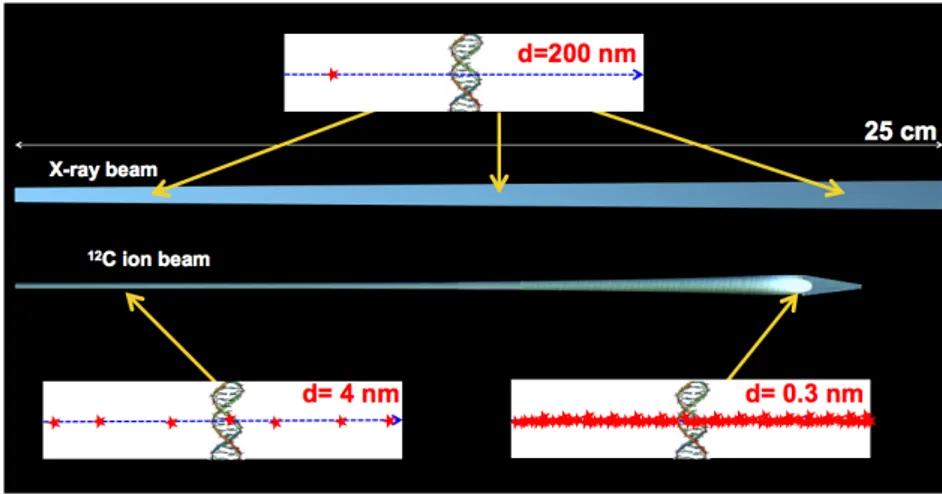
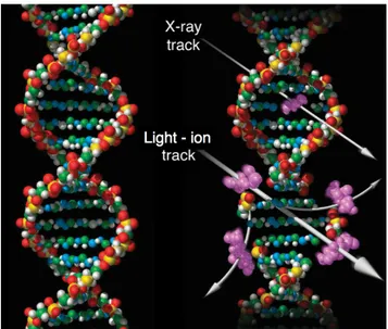
In recent years, the rapid advance in technology has led to the evolution of radiation oncology techniques. About sixty years ago, an alternative to the traditional radiotherapy involving X-rays has been proposed: the hadrontherapy. Hadrontherapy, or Particle Therapy (PT), employs hadrons (from the greek adrós, strong), which are composite particles made of quarks held together by the strong force. The advantage of using these particles in cancer treatment with respect to X-rays is due to their peculiar mechanism of energy loss in matter. The hadrons released energy per unit mass (dose), that is related to the cells killing power, is very low at the beginning of the tissues penetration and it’s maximum at the end of the particle range, in a narrow region called the Bragg peak. Instead, the X-rays dose release follows an exponential decrease distribution as a function of the depth into the absorbing medium, with a non negligible dose released to healthy tissues surrounding the tumor. Another advantage in using hadrons is their high biological damage with respect to X-rays, especially for light ions (–,12C ...). X-rays passing through matter
have a low ionization density, producing free-radicals and then inducing the cells damage mostly in an indirect way. Instead, light ions are characterized by a high ionization density which is maximum at the Bragg peak, producing direct breaks of the DNA helix (strand breaks or double strand breaks) causing the cells death. Hence, since free-radicals are produced in well oxygenated tumor areas, hypoxic tumors, for example, turn out to be radioresistant to traditional RT, that becomes less effective in such cases with respect to particle therapy.
The use of hadrons in radiotherapy allows for a very selective dose release, capable of destroying cancerous cells with high efficiency and preserving the surrounding healthy tissues. Therefore, hadrontherapy is a particularly suitable technique to treat deep and radioresistant tumors close to organs at risk. On the other hand, due to the high localization of the Bragg peak, the dose release monitoring over the tumor volume in particle therapy is highly requested in order to assess the beam range inside tissues and verify the PT treatment effectiveness.
Nowadays, there are many centers all over the world using particle therapy for tumor treatment, involving mainly protons and, as a recent development, also carbon ion beams. In order to allow for a widespread clinical use of the particle therapy, a huge effort should be devoted to improve the dose monitoring devices and techniques. As of today, the only dose monitoring technique that has been attempted even on an experimental basis is the off-line PET, the Positron Emission Tomography used after the PT treatment, based on the detection of back to back photons (PET photons) produced in the positrons annihilation following a radioactive isotope beta decay. Such isotopes are created by the interactions of the hadron beam with the target. The PET based monitoring technique suffers, mainly, for the reduced statistics available that limits the imaging resolution achievable.
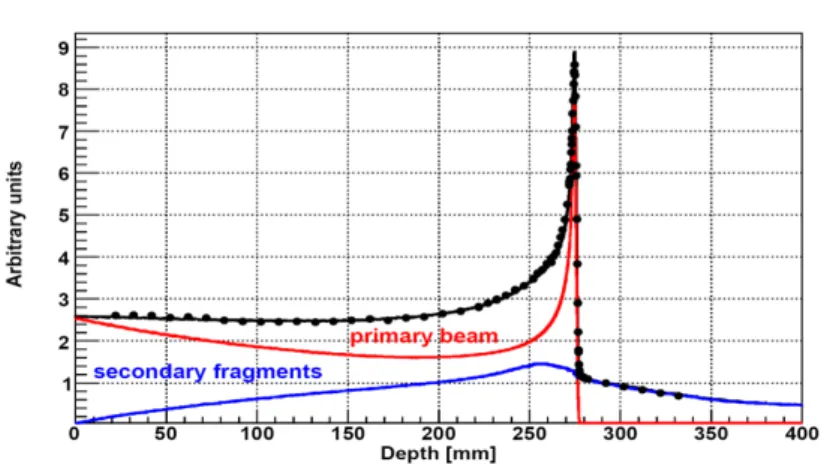
New methods, based on the detection of secondary fragments produced in the nuclear interactions of the hadron beam projectiles with the target nuclei, aiming for an on-line dose release monitoring capable of being operated during the radiation treatment, are under study. The secondary particles available for such studies, emitted within few nanoseconds from the time of interaction, can be either prompt photons or charged particles.
The work presented in this thesis describes a novel approach for an on-line dose release monitoring in PT treatments. In Chapter 1 I will first review the basics of the interaction of radiation with matter for the particles of interest of this work. In Chapter 2 I will introduce the particle therapy and its physical and biological specific variables, while in Chapter 3 I will describe in detail the characteristics of the secondary fragments produced in PT treatments, as well as their detection techniques. Chapter 4 is dedicated to the experiments performed to characterize the secondary particles production from carbon ion beams impinging on a ‘human like’ target. The energy spectrum and the flux of secondary radiation, such as prompt photons and secondary charged particles, have been measured and a clear correlation between the secondary charged particles emission profile and the Bragg peak position has been observed. The obtained results fully support the feasibility of a novel on-line dose monitoring technique based on the simultaneous detection of secondary neutral and charged radiation.
In Chapter 5 I will outline the Dose Profiler project. The Dose Profiler (DP) is a 4
dual-mode device designed to track both neutral and charged particles during the hadrontherapy treatment, in order to measure the emission distribution of secondary fragments and relate it to the beam dose release inside the patient.
The DP is under construction and it has been developed as part of the INSIDE project aiming for a combined multi-mode on-line dose release monitor, compact and manageable, that will be integrated in a treatment room at the CNAO center in Pavia (Italy) in 2016.
Chapter 1
Radiation interaction with
matter
The interaction of radiation with matter is a topic of outmost importance. In the last decades, it has driven the effort of both experimentalists and theoreticians in order to improve the knowledge of interaction mechanisms and allow a widespread of techniques and applications that are related to such phenomena. The design and characterization of novel radiation detection techniques, the optimization of radiation shielding materials and the implementation of radiation techniques for tumor treatments are all examples of such applications.
Depending on the radiation type, energy and target material, radiation interaction with matter is driven by quantum mechanics, that rules the propagation of radiation through matter and its detection characteristics, as well as its effects on a biological organism. Some typical processes undergone by neutral or charged radiation when passing through matter are the electromagnetic interactions and inelastic collisions with the atomic electrons. In particular, charged radiation has to be distinguished in light and heavy charged radiation, such as electrons and positrons with respect to protons, alpha particles and other ions.
Since this thesis mainly concerns medical physics application, in this chapter it will be discussed the interactions of radiation with matter that are of interest in this field.
1.1 Heavy charged particles
In this section the passage of heavy charged particles through matter is discussed, with special emphasis on the exchange of energy between the projectile particles and the target and on the deflections from the incident direction.
A charged particle impinging on a material makes collisions with the target atomic electrons and nuclei. For particles heavier than electrons, the mentioned collisions have different consequences. When entering any absorber the charged particle simultaneously interacts with many electrons, and each electron is affected by the impulse due to the Coulomb force as the heavy charged particle passes nearby. Therefore, the electron can take up an appreciable amount of energy from the incident particle, rising up to a higher-lying shell within the atom, or the atom
8 CHAPTER 1. RADIATION INTERACTION WITH MATTER can undergo ionization, when the electron is completely removed from the atom, depending on the closeness of the interaction. No significantly deflections of the primary particle trajectory will be observed, as the electron mass is much smaller than the heavy charged particle mass. Whereas, when the collisions are with the target nuclei, those absorb a very little amount of energy, since the mass of the target nuclei is usually much bigger compared to the mass of the incident particle. Because of their greater charge, massive nuclei scatter the incident particle, causing particle deflections on the trajectory that are anyhow confined to small angles. Thus, the energy loss by the heavy charged particle occurs almost entirely in collisions with electrons. Other processes responsible for the particle energy loss are the emission of Cherenkov radiation, nuclear reactions, and bremsstrahlung that are extremely rare with respect to the atomic collisions processes, so they will not be discussed in this chapter (except for the nuclear fragmentation).
When the heavy charged particle loses its energy, there is a consequent decrease of its velocity. The maximum energy that can be transferred to an electron of mass me in a single collision from a charged particle of mass M with a kinetic energy T
is actually small and equal to 4T me/M. On the other hand, many collisions occur
per unit path length, so a substantial energy loss is observed even for thin layers of material, producing a continuous decrease of particle’s velocity until the particle is even stopped. As already mentioned, the number of collisions per unit path length is usually large, causing the collisions to be statistical. Since the fluctuations in the total energy loss are small, it is possible to work with the average energy loss per unit path length, the so called stopping power dE/dx. This quantity was first calculated by Bohr using classical mechanics while Jackson has evaluated a simplified version (Jackson [1]), followed by the quantum mechanics approach of Bethe and Ashkin [2].
1.1.1 The Bethe-Bloch formula
When a heavy charged particle of charge ze and mass M collides with an atomic electron, if the particle velocity is greater than the electron orbital velocity, during the collision the bounded atomic electron can be treated as free and initially at rest. The momentum transfer can be assumed to be sufficiently small, so the particle trajectory is essentially not deflected and the recoiling electron does not move during the interaction. Another approximation is that the particle’s magnetic interaction is negligible, since the relative velocity is small. The geometry of the collision is shown in Figure 1.1, where a particle of mass M, charge ze and velocity v passes near an electron of mass m (m π M) and charge e at an impact parameter b.
1.1. HEAVY CHARGED PARTICLES 9 The approximated formula for the energy loss as evaluated by Jackson [1] express all the features of the classical result due to Bohr (1915):
≠dE dx = 4fiz2e4 mc2—2nln mc2—2“2 ~ ÈÊÍ (1.1)
where E is the particle energy, x the particle’s travelled distance in the medium, — = v/c with v the particle’s velocity and c the speed of light, z is the particle’s charge, e the electron charge (e2 = 1.44 MeV fm, it contains 4fi‘0) and m the electron rest mass; n = NAflZ
A is the electron density with NAthe Avogadro constant
(6.022045 ◊ 1023 mol≠1), Z and A respectively the atomic and mass number and fl the density of the absorber material; “ = (1 ≠ —2)≠1 is the Lorentz factor, ~ is the reduced Planck constant and ÈÊÍ is the average electron revolution frequency. It has to be underlined that for light charged particles as protons, the classical formula of the stopping power does not work properly, even if it contains all the description of the electronic collision loss. Thus, quantum effects have been taken into account and a complete quantum mechanical calculation of the energy loss has been performed by Bethe, Bloch and others:
≠dEdx = 2fiNAAZmc 2flz2r2 e —2 · C ln A 2m“2v2Wmax I2 B ≠ 2—2≠ ”(—“) ≠ 2CZ D (1.2) where re = e 2
mc2 is the classical electron radius, I is the mean ionizing potential of
the target, Wmax is the maximum energy transfer in a single collision, ”(—“) is the density correction and C is the shell correction.
The mean ionizing potential I is one of the most important terms of the Bethe-Bloch formula, and it is usually computed experimentally for each determined medium. It can be defined as:
I = ~ ÈÊÍ (1.3)
with ~ and ÈÊÍ as defined from Bohr’s formula in equation 1.1. The maximum energy transfer is produced by a head-on collision and, for an incident particle of mass M colliding with an electron of mass m, the kinematics gives:
Wmax= 2mc
2÷2
1 + 2s1 + ÷2+ s2 (1.4)
where ÷ = —“ and s = m/M. If M ∫ m then
Wmaxƒ 2mc2÷2 . (1.5)
The corrections ” and C intervene at high and low energy respectively. Consid-ering the density correction, the incident particle has an electric field that tends to polarize the atoms along its path inside the target. The effect is an intense
10 CHAPTER 1. RADIATION INTERACTION WITH MATTER full electric field that shields the electrons far from the particle trajectory. All the collisions with the outer electrons will contribute less to the total energy loss than as predicted by the equation 1.2. The shell correction, instead, arises when the velocity of the particle is comparable or even smaller than the orbital velocity of the atomic electrons. In these scenario, the hypothesis that the electron is stationary with respect to the incident particle no longer exists and the equation 1.2 is not valid anymore. Figure 1.2 shows a comparison of the total energy loss with and without the density correction and the loss from transfers of less than 10 keV for a typical medium. As can be observed, for large values of the Lorentz factor “, the density correction limits the logarithmic growth of the energy loss.
Figure 1.2. Total energy loss and loss from individual energy transfers of less than 10 keV,
including the density effect (solid lines). The total energy loss without density correction is also shown (dotted line) (Jackson [1]).
Stopping power energy dependence
The dependence of the stopping power as a function of the kinetic energy for different particles is shown in Figure 1.3.
For a non relativistic particle, dE/dx is dominated by the overall factor 1/—2 and decreases with increasing velocity until a minimum is reached at v ≥ 0.96c. At this point, particles are usually referred to as Minimum Ionizing Particles (MIP). As the energy increases beyond the MIP point, the term 1/—2 becomes almost constant and dE/dx rises again due to the logarithmic contribution in equation 1.2. Anyway, the relativistic rise is compensated by the density correction, as previously shown in Figure 1.2. When different charged projectiles with the same velocity are com-pared, z is the only factor that change outside the logarithmic term in equation 1.2. Therefore, particles with greater charge will have a larger specific energy loss. The study of dE/dx for different materials as absorbers has also shown the energy loss dependence on the electron density of the medium: the higher density materials, the higher energy loss.
1.1. HEAVY CHARGED PARTICLES 11
10 CHAPTER 1. INTERACTION OF RADIATION WITH MATTER
Figure 1.2:The stopping power, dE/dx, as function of energy for different particles. From Leo [3].
Figure 1.3:A typical Bragg curve showing the variation of dE/dx as a function of penetra-tion depth of 5.49 MeV particles in air (from241Am radioactive decay). It is clear how the particles are more ionizing towards the end of their path.
kinetic energy changes. This effect is shown in Figure 1.3, which shows the amount of energy deposited by a heavy particle as a function of its penetration depth inside the absorbing medium. This is known as a Bragg curve, and, as can be noted, most of the energy is deposited near the end of the path. At the very end, however, the particle begins to pick up electrons for part of the time, this lowers the effective charge of the projectile and thus the dE/dx drops.
Figure 1.3. The stopping power as a function of the kinetic energy for different particles
(Leo [3]).
Taking into account all the aforementioned considerations, a heavy charged particle deposits more energy per unit path length at the end of its path inside the target, rather than at its beginning, as shown in Figure 1.4. The amount of ionization created by a heavy charged particle as a function of its penetration depth inside the target is known as the Bragg curve. This behaviour can be explained observing that since the particle spends a longer time in the proximity of any given electron when its velocity is low, the impulse felt by the electron, and so the energy transferred, is larger. At the very end of the Bragg curve, the incoming particle begins to pick up electrons, lowering the effective charge of the projectile and thus the dE/dx drops.
Figure 1.4. A typical Bragg curve shows the stopping power of air for 5.49 MeV – particles
12 CHAPTER 1. RADIATION INTERACTION WITH MATTER 1.1.2 Range
The range of a particle is its penetration depth through a traversed medium until the particle loses all its energy. The range of a particle depends on the type of the particle, on its initial energy and on the material traversed. From an experimental point of view, the range can be measured using a collimated beam of fixed energy particles impinging on a material of different thickness (t) and measuring the ratio of transmitted to incident particles (I and I0 respectively). Figure 1.5 shows a typical plot of the ratio I/I0 in function of the absorber thickness t. As it can be observed for
1.1. HEAVY CHARGED PARTICLES 11
Range
The penetration depth of a particle traversing a medium before it loses all of its energy is called range. Since the energy loss of charged particles can be safely as-sumed to be continuous, this distance must be a well defined quantity, the same for identical particles with the same energy traveling in the same material. Experimen-tally, the range can be determined by passing a collimated source of particles at a fixed energy through the medium under test varying its thickness and measuring the ratio of transmitted to incident particles. A typical plot of this curve versus absorber thickness is shown in Figure 1.4. As it can be seen, for small thicknesses, almost all the particles survive. As the thickness approaches the range value, surprisingly, this ratio does not drop immediately to zero, as expected of a well defined variable. The curve slopes down, instead, over a certain range of thicknesses. This fact can be
Figure 1.4:Range (R) vs absorber thickness (t) plot for an alpha particle collimated source.
I0is the incident intensity, I is the transmitted intensity.
only explained assuming the energy loss mechanism not continuous, but statistical in nature. Thus, in general, two identical particles with the same initial energy traveling in the same material, will not undergo the same number of collisions and hence the same energy loss. This phenomenon is known as range straggling. In a first ap-proximation, the distribution of ranges for a set of identical particles has a gaussian shape. Its mean value ( ¯R) is called the mean range and corresponds to the midpoint on the descending slope of Figure 1.4. This is the thickness at which roughly half of the particles pass through the material. In the practice, another quantity of interest is the thickness at which all the particles are absorbed, this point is usually evaluated by taking the tangent to the curve at the midpoint and extrapolating to the x axis intercept (R0). This parameter is usually referred to as the extrapolated range.
Figure 1.5. A typical range number-distance curve for an alpha particle collimated source. small thicknesses almost all the particles survive (I = I0). As the material thickness approaches the range value, the I/I0 ratio does not drop immediately to zero, but it slopes down with a non zero spread of thicknesses. This behaviour is named range straggling and can be justified by the statistical nature of the energy loss mechanism. Therefore, two identical particles with the same initial energy traveling in the same material will not undergo the same number of collisions and hence the same energy loss. In a first approximation, the range straggling measured for a set of identical particles has a gaussian shape, where the gaussian mean value is called the mean range ¯R, corresponding to the point in the middle of the descending slope, as can be seen in Figure 1.5. Thence, for a thickness t = ¯R almost half of the incident particles are absorbed, but the interesting thickness value, where all the particles are absorbed, can be extrapolated by taking the tangent to the range number-distance curve at the ¯R point and its t axis intercept (R0). This parameter is usually known as the extrapolated range.
1.1.3 Nuclear fragmentation
The nuclear fragmentation is a nuclear physics process that occurs after the nuclei interactions. It has to be taken into account when heavy charged particles accelerated to energies up to hundreds of MeV are involved.
The nuclear collisions of the particle projectile with the target nuclei can be dis-tinguished in central (or near central) and peripheral collisions depending on the size of the impact parameter with respect to the size of the interacting particles. Central collisions occur for small values of the impact parameter, with the subse-quent complete fusion of the projectile and target nucleus. On the other hand, the peripheral collisions occur with increasing size of the impact parameter, where the overlapping region between the projectile and the target nucleus is small inducing their incomplete fusion (see Fig. 1.6).
1.1. HEAVY CHARGED PARTICLES 13
Figure 1.6. Semi-classical representation of the nuclear reaction mechanisms.
The Complete Fusion (CF) and Incomplete Fusion (IF) cross sections change as a function of the projectile energy. At high energies the CF probability is very low while the IF probability is very high. Instead at low energies, in the Bragg peak region, the CF probability reaches values of ≥ 40 ≠ 50% or even more, depending also on the projectile mass.
According to Serber [4], inelastic nuclear reactions at relativistic energies occur in two different steps, defining two different time scales. The first interaction transfers a certain amount of excitation energy to a target nucleus, in a characteristic time of 10≠23 s, and the composition of the reaction partners can be modified. This step is called as the abrasion process. In the second step, called ablation, the nucleus de-excitation takes place by evaporation of neutrons, protons and light nuclei, fission and gamma rays emission. The characteristic time for particles emission varies in a range between 10≠21 s to 10≠16 s for an excitation energy of 200 MeV and 10 MeV, respectively.
1.2. ELECTRONS AND POSITRONS
13
Figure 1.5:
A simplified sketch of the abrasion-ablation model of the nuclear fragmentation due to peripheral collisions of projectile and target nucleus as described by Serber [4].and clusters from target-like fragments are emitted isotropically and with much lower
velocities. The particles ablated from the fireball cover the range between the
projec-tile and target emission.
1.2 Electrons and positrons
Collisional and radiative energy loss
Like heavy charged particles, electrons and positrons also suffer a collisional
en-ergy loss when passing through matter. But, while the basic mechanism of collision
loss outlined for heavy charged particles is also valid for electrons and positrons,
the Bethe-Bloch formula must be slightly modified for two reasons. Firstly for their
small mass: the assumption that the incident particle remains undeflected during the
collision is, in fact, invalid. Large deviations in the electron path are now possible,
because its mass is equal to that of the orbital electrons with which it is interacting.
Secondly, since the collisions are between identical particles, a much larger fraction
of energy can be lost in a single encounter. A number of terms must be then changed
in the equation (1.2), in particular, the maximum allowable energy transfer becomes
W
max= T
e/2, where T
eis the kinetic energy of the incident electron (or positron).
Furthermore, because of their small mass an additional loss mechanism comes
into play: the emission of electromagnetic radiation arising from scattering in the
electric field of a nucleus (bremsstrahlung). From classical theory, any charge must
radiate energy when accelerated, and the deflection of the electron (or the positron)
in its interactions with the absorber’s nuclei corresponds to such acceleration. The
linear specific energy loss through this radiative process is given by:
dE
dx
rad=
N T
eZ (Z + 1) e
4137 (m
ec
2)
24 ln
2E
m
ec
24
3
(1.4)
Figure 1.7. Scheme of the abrasion and ablation nuclear processes occurring in the
peripheral collision between a particle projectile (light grey) and a target nucleus (dark grey), producing secondary neutral and charged fragments.
Bowman, Swiatecki and Tsang [5] introduced the abrasion-ablation model, schematically shown in Figure 1.7. In the overlapping zone between the parti-cle projectile and target nuparti-cleus, nuparti-cleons are abraded and the hot reaction zone (fireball) is created, while the outer nucleons (spectators) are only slightly affected by the collision. The fireball is a composite nucleus and the energy initially
concen-14 CHAPTER 1. RADIATION INTERACTION WITH MATTER trated on a few nucleons spreads through the composite nucleus in order to reach the equipartition of the excitation energy, i.e. the state of statistical equilibrium. In this phase called thermalization particles can be emitted into the continuum with energies higher than if they would be emitted by a fully-equilibrated nucleus. Such continuous emission is called the pre-equilibrium emission.
When the statistical equilibrium is achieved, the fragments emission stops and if the composite nucleus is not in the fundamental state, as well as the particle and target fragments, the ablation process occur: the fireball and the fragments undergo by de-excitation by evaporating nucleons, light clusters and gammas (prompt gamma emission). The secondary products emitted by the projectile fragments are forward peaked in the laboratory frame, due to the high velocity of the projectile, having almost the same velocity of the primary particle. On the other hand, neutrons and clusters produced by the target fragments are emitted isotropically and with much lower velocities. The particles ablated from the fireball cover the range between the projectile and target emission.
Figure 1.8. FLUKA simulation of kinetic energy (left) and angular (right) distributions of
the yield (Nprod/NC) of secondary fragments produced in the interaction of a 400 MeV/u 12C ion beam impinging on a carbon target 5 mm thick. The angular distribution is
reported for fragments with kinetic energy T > 30.0 MeV/u (Pleskac et al. [6]).
Figure 1.8 shows a simulation with the Monte Carlo FLUKA code (Ferrari et al. [7]) of the kinetic energy (left) and angular (right) distributions of the yield of secondary fragments (Nprod) produced in the interaction between 400 MeV/u 12C ions (NC) impinging on a carbon target 5 mm thick (Pleskac et al. [6]). The fragments kinetic energy per nucleon is peaked at the primary carbon energy and the angular distribution shows that Z Ø 2 fragments are emitted within 12¶, while neutrons and hydrogen ions cover a wider angular range.
1.2 Electrons and positrons
Like heavy charged particles, electrons and positrons also suffer a collisional energy loss when passing through matter, but their small mass change some assumptions on the interaction’s behaviour between the incident particle and the material. A large deflection from the primary electron (or positron) direction has to be taken into account and an additional energy loss mechanism comes into play, the bremsstrahlung. In this section, the main processes occurring in the electron and positron interactions with matter will be described.
1.2. ELECTRONS AND POSITRONS 15 1.2.1 Collisional and radiative energy loss
With respect to heavy charged particles, electrons and positrons Bethe-Bloch formula must be slightly modified. Electrons and positrons mass is equal to that of the orbital electrons with which they interact, causing large deviations in the electron path, while for incident heavy charged particle the assumption that it remains undeflected during the collision was made.
Since for electrons the collisions are between identical particles, a much larger fraction of energy can be lost in a single impact. Equation 1.2 has to be modified, starting from the maximum energy transfer that is Wmax = Te/2, where Te is the kinetic energy of the incident electron (or positron). Furthermore, because of their small mass, an additional energy loss mechanism occurs: the emission of electromagnetic radiation arising from scattering in the electric field of a nucleus (bremsstrahlung). From classical theory, any charge must radiate energy when accelerated, causing both energy loss and angular deflection of the interacting electron (positron). The total energy loss of positrons and electrons can be expressed by the sum of two terms: ≠ 3dE dx 4 tot= ≠ 3dE dx 4 rad≠ 3dE dx 4 coll . (1.6)
The linear specific energy loss through the radiative process is given by: ≠ 3dE dx 4 rad = 4–NA Z(Z + 1) A r 2 eEln 287 Z1/2 (1.7) where – = e2
~c is the fine structure constant and the other quantities are defined as in equation 1.1. This radiation component exists also for heavy charged particles, but it is generally negligible for the energies of interest of this thesis.
Radiative losses depend strongly on the absorbing material and they increase sig-nificantly in materials with high atomic number. It is possible to define for each material a critical energy Ec at which the radiation loss is equal to the collision loss:
3dE dx 4 rad = 3dE dx 4 coll for E = Ec . (1.8)
Above the critical energy, the radiation component will dominate over the collision component and vice-versa. Bethe and Heitler evaluated an approximated formula to estimate Ec:
Ec ƒ 1600mc
2
Z . (1.9)
Table 1.9 shows a short list of critical energies for several materials commonly used in experimental physics applications. As the energy is increased, the probability of bremsstrahlung rapidly rises, so that at a few tens of MeV radiation loss is comparable to or even greater than the collision loss.
16 CHAPTER 1. RADIATION INTERACTION WITH MATTER
Figure 1.9. Critical energy values of some materials.
1.2.2 Multiple Coulomb scattering
When charged particles cross matter, together with inelastic collisions with atomic electrons, also repeated elastic Coulomb scatterings from target nuclei occur. In a first approximation, the cross section of these collisions can be described by the Rutherford formula: d‡ dcos ◊ = Z 2r2 e (mc/—p)2 4 sin4(◊/2) (1.10)
where ◊ is the deflection angle from the particle trajectory. Assuming that the target nuclei mass is much greater than the incident particle mass, so that the energy transfer to the nucleus is negligible, the majority of such elastic scattering result in a small angular deflection, due to the (sin4(◊/2))≠1 cross section dependence. There are three different types of Coulomb scattering that can take place:
• Single Scattering: when the absorber is very thin such that the probability of more than only one Coulomb scattering is very small. The angular distribution is then given by the Rutherford equation 1.10.
• Plural Scattering: when the average scattering number is N < 20. This is the most difficult case to treat since neither the Rutherford formula nor statistical methods can be applied.
• Multiple Scattering: when the average number of collisions is N > 20 and the energy loss is small or negligible. The problem can be treated statistically to obtain the probability distribution for the net deflection angle as a function of the material traversed thickness.
The multiple scattering (MS) is the most frequently case found in common appli-cations. Rigorous calculations of multiple scattering are extremely complicated but the mainly used ones are the small angle approximations by Molière and by
1.2. ELECTRONS AND POSITRONS 17 Snyder and Scott. Their formulations have been demonstrated to be generally valid for almost all particles up to angles of ◊ ƒ 30¶. Ignoring the small probability of large-angle single scattering, the effect of multiple scattering in a given material can be obtained by considering the distribution resulting from the small angle (◊ < 10¶) single scattering only. Then the probability distribution is approximately Gaussian and can be written as follows:
P(◊)d ƒ 2◊ È◊2Íexp A ≠◊2 È◊2Í B d◊ . (1.11)
The parameter +◊2, represents the variance of the scattering angle distribution, obtained by the integral:
⁄
◊2P(◊) d . (1.12)
The square rootÈ◊2Í is known as the RMS scattering angle. However, a better estimation is obtained by using an empirical formula proposed by Highland [8] which is valid to within 5% for target atomic number Z > 20 and for target thickness 10≠3L
rad < x <10Lrad. An empirical estimation of the Gaussian sigma is:
‡◊[rad] = 14.1[MeV] p—c Z Ú x Lrad 3 1 +19log10 x Lrad 4 (1.13) with Lrad the material’s radiation length, x the material’s thickness and p the
particle’s momentum. Therefore, the multiple scattering effect is enhanced for high Z targets and it increases as the particle energy decreases, due to the (1/p—c) term. On the other hand, thin absorbers (low x values) reduce the angular spread of the trajectory of the incident particle.
1.2.3 Backscattering of low energy electrons
Because of the small mass, electrons suffer from large deflection angles by scattering from target nuclei. An electron entering an absorber surface can undergo to such great deflection that it is backscattered out of the absorber, as illustrated in Figure 1.10.
18 CHAPTER 1. RADIATION INTERACTION WITH MATTER
1.2. ELECTRONS AND POSITRONS 17
Figure 1.6: Fraction of normally incident electrons that are back scattered from thick slabs of various materials, as a function of incident energy E. From Tabata et al [7].
Electron energy (MeV)
Scintillator 0.25 0.50 0.75 1.0 1.25 Plastic 0.08 ± 0.02 0.053 ± 0.010 0.040 ± 0.007 0.032 ± 0.003 0.030 ± 0.005 Anthracene 0.09 ± 0.02 0.051 ± 0.010 0.038 ± 0.004 0.029 ± 0.003 0.026 ± 0.004 NaI (Ti) 0.450 ± 0.045 0.410 ± 0.010 0.391 ± 0.014 0.375 ± 0.008 0.364 ± 0.007 CsI (Ti) 0.49 ± 0.06 0.455 ± 0.023 0.430 ± 0.013 0.419 ± 0.018 0.404 ± 0.016
Table 1.3: Fraction of normally incident electrons backscattered from various detector sur-faces. From Titus [8].
Positron interactions
The Coulomb forces that constitute the major mechanism of energy loss for both electrons and heavy charged particles are present for either positive or nega-tive charge on the particle. Whether the interaction involves a repulsive or attracnega-tive force between the incident particle and orbital electron, the impulse and energy trans-fer for particles of equal mass are about the same. Therefore, the tracks of positrons in an absorber are similar to those of electrons, and their specific energy loss and range are about the same for equal initial energies. Positrons differ significantly in the annihilation radiation (of two collinear 0.511 MeV photons) that is generated at the end of positron track. Because these 0.511 MeV photons are very penetrating compared with the range of the positron, they can lead to the deposition of energy far from the original positron track. This unique feature of positrons must be seriously taken into account in the project and the design of a gamma-ray detector, especially Figure 1.11. Fraction ÷ of normally incident electrons that are backscattered from a thin
slab of various materials, as a function of the incident energy E (Tabata et al. [9]).
The probability of this phenomenon is higher for electrons with energy less than 10 MeV and absorbers with high atomic number.
The backscattering process has a significant effect on the response of detectors designed to measure the low energy of incident electrons, since backscattered electrons do not deposit all their energy in the absorbing medium. As an example, for non-collimated electrons impinging on a high Z material such as NaI, as much as 80% may be scattered back. The measured ratio (÷) of backscattered electrons to incident electrons as a function of the electrons incident energy E is shown in Figure 1.11. The primary electrons are mono energetic and perpendicularly incident on the surface of various materials.
1.3 Photons
At the energy of interest of this work (100 keV ≠ 10 MeV) photons interact with matter via three principal mechanisms: photoelectric absorption, Compton scattering and pair production. All these processes lead to the partial or complete photon energy transfer to atomic electrons. In this section such processes will be described. 1.3.1 Photoelectric absorption
In the photoelectric effect a photon is absorbed and gives all of its energy to an atomic electron. In the interaction the atom can be ionized ejecting the electron, usually referred to as photoelectron, from one of the atom’s bound shells. This interaction cannot take place with free electrons, since a free electron cannot absorb a photon and also conserve momentum. For bounded electrons the nucleus absorbs the recoil momentum instead. Thus, the photoelectron energy is:
E = h‹ ≠ B.E. (1.14)
with B.E. the electron binding energy. The photoelectric effect is therefore observed only for photon energies greater than the binding energy of the atomic electrons. The applications of this process include virtually all dental and medical diagnostic
1.3. PHOTONS 19 X-rays, airport baggage inspection X-rays, and X-rays emitted during relaxation of the atomic electrons following radioactive nuclear decay.
1.3. PHOTONS
19
Figure 1.7:
Gamma-ray total cross section for carbon, where: p.e., Rayleigh, Compton, nuc, e are the photoelectric effect, coherent scattering, incoherent scattering, pair produc-tion in nuclear field and pair producproduc-tion in electron field components respectively.Z
materials are the most favored for photoelectric absorption and, as will be
dis-cussed in later chapters, are an important resource when choosing the best material
for gamma-ray detectors.
Compton scattering
The interaction process of Compton scattering arises when an incoming photon
is scattered on electrons. In matter, of course, the electrons are bound but, if the
photon energy is high, with respect to the binding energy, this latter component can
be neglected and the electrons can be considered as basically free. Hence, the
pho-ton is deflected through an angle with respect to its original direction (shown in
Figure 1.8). The photon transfers a portion of its energy to the electron (considered
initially at rest) which is then referred to as recoil electron. Since all angles are
possible, the energy transfer can vary from zero to a large fraction of the primary
energy. The expression of the scattered photon energy as a function of the scattering
angle, shown in equation (1.12), and the expression of the photon scattering angle,
as a function of the incoming photon energy, shown in equation (1.13), can simply
Figure 1.12. Photons total cross section ‡tot as a function of the photon energy in carbon,
with the contribution of: ‡p.e. = photoelectric effect, ‡Rayleigh = Rayleigh (coherent)
scattering, ‡Compton = incoherent scattering, Ÿnuc = pair production in nuclear field, Ÿe= pair production in electron field.
Figure 1.12 shows the photon total cross section ‡tot and all the contributions of different processes as a function of the photon energy for a carbon target. The K-shell electrons are the most tightly bounded, and are the most important contribution to the atomic photoelectric cross section. However, if the photon energy drops below the binding energy of a given shell, an electron from that shell cannot be ejected. For photon energies greater that the highest atomic binding energy, the photon cross section dependence on the medium atomic number Z is given by:
‡p.e.= constant · Zn/(h‹)3 (1.15) where n is a number which varies between 4 and 5.
In high Z materials the photoelectric effect is enhanced and, therefore, high Z materials are often used to build photon detectors, as it will be discussed in next chapters.
1.3.2 Compton scattering
In Figure 1.13 (Klein and Nishina [10]) is shown the Compton scattering process: a photon collides with an electron, called recoil electron, loses some of its energy and then it is deflected from its original direction.
20 CHAPTER 1. RADIATION INTERACTION WITH MATTER
Figure 1.13. Scheme of the Compton scattering of an incoming photon with energy h‹0
with a free electron at rest in the origin of the reference coordinate system. h‹ is the energy of the scattered photon while E is the energy of the scattered electron.
If the photon energy is much higher with respect to the electron binding energy, the electron can be considered as basically free. The relation between the photon deflection angle ◊ and the energy loss in the Compton scattering arises from the momentum and energy conservation laws in the interaction between the photon and the recoiling electron. The kinematics of the photon and of the scattered electron can be described by the following equations:
h‹= h‹0 1 +1 h‹0 mec2 2 (1 ≠ cos ◊), (1.16) E= h‹0≠ h‹ = mec2 2(h‹0) 2cos2„ (h‹0+ mec2)2≠ (h‹0)2cos2„ , (1.17) tan „ = 1 1 +1 h‹0 mec2 2cot◊2 (1.18)
where h‹0 and h‹ are the initial and final energy of the photon and ◊ is the photon scattering angle. E is the recoil energy of the electron, scattered with an angle „, me is the rest mass of the electron and c is the speed of light.
The probability of the occurrence of Compton scattering per atom of the absorber depends on the number of electrons available and therefore increases linearly with the atomic number Z of the target material. The contribution of the Compton scattering cross section ‡Compton to the total photon cross section as a function of the photon energy is shown in Figure 1.12 for a carbon target.
‡Compton decreases with increasing photon energy. The Compton scattering cross section is known as the Klein-Nishina formula and is given by:
d‡C d = 1 2 r02(1 + cos2◊) [1 + Á(1 ≠ cos ◊)]2· I 1 +(1 + cosÁ22(1 ≠ cos ◊)2 ◊)[1 + Á(1 ≠ cos ◊)] J (1.19)
1.3. PHOTONS 21 with r0 = mee2c2 the classical electron radius and Á = mh‹e0c2. Figure 1.14 shows the
scattered photon angular distribution. An enhancement of the forward scattering at high photon energy values is clearly shown.
0 10 20 30 40 50 60 70 80 0 30 60 90 120 210 240 270 300 330 0.01MeV 0.016MeV 0.2MeV 0.5MeV 1.2MeV 3.0MeV d σσσσ C /d ΩΩΩΩ , 10 -27 cm 2 str. -1 electron -1 θ θ θ θ deg.
Figure 1.14. Polar plot of the differential cross section of Compton scattering for different
initial photon energy values.
1.3.3 Pair production
The most frequent photon interaction at energies larger than twice the electron mass is the pair production, where the incident photon disappears and an electron-positron pair is created. From the energy and momentum conservation laws, the pair production occurring in the field of a nucleus of mass M (M ∫ me) has an
energy threshold of Tthr= 2mec2 = 1.022 MeV.
All the photon energy exceeding the pair production energy threshold goes into kinetic energy shared by the electron and the positron. The positron will subsequently slow down in the absorber and annihilate with another electron of the medium, producing two annihilation photons.
The pair production cross section rises with energy, as shown in Figure 1.12. The main contributions to the pair production cross section are due to the photon interactions with nuclei (Ÿnuc) and electrons (Ÿe) and it varies with the absorber
atomic number as:
Ÿnuc≥ Z2 , Ÿe≥ Z . (1.20)
Ÿe is of minor importance, except for low-Z materials.
22 CHAPTER 1. RADIATION INTERACTION WITH MATTER direction of the produced electron (or positron) is:
׳ mec 2
h‹ . (1.21)
1.3.4 Attenuation coefficient
The total interaction probability for a photon can be expressed as the sum over contributions of the principal cross sections aforementioned. Following the notation introduced in Figure 1.12, the total cross section ‡tot is:
‡tot = ‡p.e.+ ‡Compton+ Ÿnucl+ Ÿe . (1.22)
The total absorption coefficient (µ) is given by the probability per unit length for an interaction to occur and it can be obtained multiplying ‡tot by the atom density N:
µ= N‡tot= ‡tot(NAfl/A) (1.23)
where NA is the Avogadro’s number, fl is the material density and A is the relative
atomic mass of the material. The total absorption coefficient is also the inverse of the mean free path of a photon in the target. For a narrow beam of mono energetic photons with an incident intensity I0 that penetrates a thickness x of material with a density fl, the fraction of photons emerging with an intensity I can be expressed as:
I/I0 = exp[≠(µ/fl)x] . (1.24)
In the next chapter will be introduced the particle therapy and its main physical and biological aspects. PT exploits the characteristics of the interactions of radiation with matter described in this chapter in order to treat patients affected by cancer.
Chapter 2
Particle Therapy
Radiation therapy is one of the essential instruments for cancer treatment, and nowadays it is used to treat localized malignant tumors, alone or combined with chemotherapy or surgery.
Ionizing radiations are a powerful tool for human cells killing, since a high dose of radiations can control the tumor growth and efficiently destroy the tumor. Nev-ertheless, the presence of healthy cells surrounding the tumor volume limits the effective dose that can be delivered to the target: during a radiation treatment the dose release in tissues before and around the tumor area must be taken into account. Therefore, the dose delivered to the cancer cells is limited to the dose absorbed by healthy tissues.
Conventional RT uses X-rays (high energy photons or electrons) with an energy up to 25 MeV. The X-rays dose release in tissues is peaked at the beginning of their path in the patient, and it decreases with the penetration depth in tissues. An example of 21 MeV photons dose release in water is shown in Figure 2.1.
X-ray beams are produced by electron linear accelerators (linacs). Today there are almost 10, 000 linacs installed and operational in hospitals all over the world and radiation therapy is used every year more than about two-third of all cancer patients. In the last decade the interest on another type of radiation therapy for tumor treatment has rapidly grown. The so called Particle Therapy (PT), or hadrontherapy1, is based on protons or light ions as carbon ions. The use of such beams for medical applications was first proposed in the late 1946 by Robert R. Wilson.
At the Berkley laboratory, Wilson observed that the released dose profiles of charged particles as a function of their penetration in water were characterized by a small dose release at the beginning of ions path and by a maximum at the end of their range called the Bragg peak (see Figure 2.1). Wilson, in his paper, wrote: “The intense specific ionization of alpha particles [...] will probably make them the most desirable therapeutically when such large alpha particle energies are attained” [12]. Thus, charged particles have started to be used to treat deep sited tumors due to the high localization of their dose released that allows for a high efficiency in killing cancer cells, sparing healthy tissues and organs at risk. Following the Wilson’s idea,
1Hadrontherapy is a common word that indicates all kind of particle therapies that use “light”
particle beams such as protons, neutrons, pions and helium ions (alpha particles), carbon, oxygen ions and so forth (Amaldi [11]).
26 CHAPTER 2. PARTICLE THERAPY
Figure 2.1. Relative dose in function of the depth in water for 21 MeV photons (blue line),
270 MeV/u12C ions (red line) and 148 MeV/u protons (green line).
the first patient was treated in 1954 with an hydrogen beam and helium and neon beams have been employed in 1957 and 1975, respectively. In those years about 1, 000 of patients affected by tumors experienced the radiation therapy with protons. In Europe, at the Uppsala cyclotron in 1957, B. Larsson treated the first cancer case with protons, while in 1970s, at the LBL, the hadrontherapy with ions heavier than protons began to be tested, from Cornelius A. Tobias’ suggestions (Tobias et al. [13]). Concerning the present situation, in October 2014 the Particle Therapy Co-Operative Group (PTCOG), an international institution that monitors the hadrontherapy facilities all around the world, published that 95, 429 patients have been treated with protons and more than 10, 000 with carbon ions, as shown in Table 2.1.
In Europe, the development of proton therapy in cancer treatment first occurred in Villigen (Switzerland), at the Paul Scherrer Institute (PSI) (Pedroni et al. [14]), while carbon ion therapy first took place in Darmstadt (Germany), at the GSI Helmholtz Centre for Heavy Ion Research (Haberer et al. [15]). Then in Heidelberg (Germany) the Heidelberg Ion Therapy center (HIT) (Haberer et al. [16]) was built. CATANA [17] has been the first hadrontherapy center in Italy, at Laboratori Nazion-ali del Sud of the National Institute of Nuclear Physics (LNS - INFN) in Catania, and it deals with choroidal and iris melanomas. CATANA treated its first patient in 2002 and since then, other 349 patients have been irradiated with protons [18]. The other operational center in Italy is the Centro Nazionale di Adroterapia On-cologica (CNAO) in Pavia [19], that treated its first patient with protons in 2011 and the year after it started to use also carbon ion beams. Together with the HIT center in Heidelberg, CNAO is the only facility in Europe that allows both for proton and carbon ion therapy. In 2014 the proton facility ATreP in Trento (Italy) also became operational and the first patient has been treated in October 2014.
2.1. PHYSICAL ASPECTS 27 In this chapter the physical and biological aspects of particle therapy will be described. The main techniques of beam delivery will be introduced and a short review of the status and prospects of particle therapy will be presented.
Table 2.1. Geographical distribution of particle therapy facilities until October 2014. Data
from Particle Therapy Co-Operative Group 2014 survey [18].
2.1 Physical aspects
In this section, the fundamental physic quantities that characterize the particle therapy are outlined.
2.1.1 Absorbed Dose
Radiobiological and clinical effects in radiation therapy are correlated to the absorbed dose, a physical quantity defined in equation 2.1 as the mean energy deposited by ionizing radiation (E) per unit mass (m) (ICRU report [20]):
D= dE
dm . (2.1)
In the international system of unit (SI) the dose unit of measurement is the gray and 1 Gy corresponds to 1 J of absorbed radiation by 1 kg of mass (1 Gy = 1 J/kg). The released dose in a thin slice of absorber material with mass density fl for a parallel particle beam with fluence F (dN particles traversing a surface dS) can be calculated as: D[Gy] = 1.6 ◊ 10≠9◊dE dx 5keV µm 6 ◊ F [cm≠2] ◊ 1 fl C cm3 g D (2.2)
28 CHAPTER 2. PARTICLE THERAPY where dE/dx is the stopping power, defined in the previous chapter (see Sec-tion 1.1.1).
2.1.2 Linear Energy Transfer
The Linear Energy Transfer (LET) refers to the transferred energy from a ionizing radiation to a medium. It describes how much energy a ionizing particle transfers to the traversed matter per unit distance and it is equal to the breaking force acting on a charged ionizing particle traveling inside a material. The LET is then related only to the energy loss of the charged particle due to electronic collisions. The unit of measurement for the LET is the keV/µm. The LET is directly coupled to the DNA damages, but it limits the radiation range in matter. Therefore, the linear energy transfer is closely related to the stopping power.
Figure 2.2. Comparison between proton and carbon tracks at different energies. Protons
energy loss is small and single following events occur distant from each other, implying the DNA lesions repair. For carbon ions the ionization density increases with decreasing energy, i.e. at the end of the particle path in tissues, producing multiple localized damages to the DNA molecule (Fokas et al. [21]).
When a charged particle crosses a medium, secondary electrons are produced by ionization processes. If their energy is large enough to allow further medium ionizations, secondary electrons are called delta rays. It can be of interest to focus on the energy transferred in the proximity of the primary particle track, excluding the interactions that produce delta rays with energies larger than a determined value . In this approach secondary electrons that carry energy far from the primary particle track are not taken into account, since larger energy implies larger range (see
2.1. PHYSICAL ASPECTS 29 Section 1.1.2). The directional distribution of secondary radiation and the non-linear path of delta rays are then neglected. The result of this approach is the restricted linear energy transfer:
L = dE
dx (2.3)
where dE is the energy loss of the charged particle due to the electronic collisions when traversing a distance dx, without taking into account all secondary electrons with kinetic energies larger than .
In the æ Œ limit the linear energy transfer becomes the unrestricted LET which is equal to the linear electronic stopping power (see equation 1.2).
Photons and protons have a sparse ionization density and so are called low-LET radiation, while carbon ions are high-LET particles due to their larger ionization density as shown in Figure 2.2. On the other hand, it has to be considered that protons can reach high LET values at the end of their range in tissues (in proximity of the BP). Details on the DNA damages due to ionization processes are given in Section 2.2 concerning particle therapy biological effects.
2.1.3 Energy deposition
While photons energy released decreases exponentially with the penetration depth (see Figure 2.1), showing a maximum between 1÷3 cm for photon energies of interest in radiotherapy, charged particles lose their energy per unit length following the Bethe-Bloch formula defined in Section 1.1.1. Equation 1.2 shows that in the entry channel of the particle in the target, i.e. for high velocity, the energy loss is small, while it maximizes at the end of the particle range, when the particle is about to stop in the target. The particle range inside the target, described in Section 1.1.2, strongly depends on the beam initial energy, so the BP position can be shifted changing the beam energy, as shown in Figure 2.3.
2.1. PHYSICAL ASPECTS OF RADIATION THERAPY 29
lows the Bethe-Bloch equation (1.2). This is characterized by a small amount of energy lost when the particle velocity is high (entry channel), while most of it is re-leased in a very narrow portion of the path, close to the end of particle range (the so called Bragg peak). Moreover, being the range a function of the energy, the depth of the Bragg peak inside the patient can be varied and adjusted by changing the energy of the beam (as shown in Figure 2.3). Thus, in a radiotherapeutic context, this sharp
Figure 2.3:Measured depth-dose curves in water for carbon ions with different beam
ener-gies. From Schardt et al. [21].
and very precise deposition could lead to a better conformation to the target volume and it could be extremely useful for treatment of deep seated tumors (where photon irradiation becomes very uneffective), or tumors near OAR. Furthermore, given the relatively low energy lost along the entry channel, the overall dose delivered to the healthy tissues surrounding the tumor is lower, as shown in Figure 2.4 and Figure 2.5, being constant the dose deposited on the tumor.
Lateral beam spread
As described in the previous chapter, the passage of a particle or, in our case of interest, a particle beam through matter will lead to a generalized diffusion of the beam itself with respect to its original direction. The beam spread is mainly caused by elastic Coulomb interactions with the target nuclei (multiple scattering), while scattering due to electronic interactions can be neglected. For small angles the
Figure 2.3. Carbon ions measured depth-dose distributions in water for different beam
![Figure 1.2: The stopping power, dE/dx, as function of energy for different particles. From Leo [3].](https://thumb-eu.123doks.com/thumbv2/123dokorg/2835450.4750/19.892.255.601.128.390/figure-stopping-power-function-energy-different-particles-leo.webp)