UNIVERSITA'DEGLI STUDI DI MESSINA
DIPARTIMENTO DI SCIENZE MATEMATICHE E
INFORMATICHE, SCIENZE FISICHE E DELLA TERRA
DOCTORAL PROGRAMME IN PHYSICS (CYCLE XXXIII)
New frontiers in cultural heritage for polychrome wooden diagnostics:
CT, MRI and micro-Raman imaging investigations.
Doctoral Dissertation
of:
Sveva Longo
S.S.D .FIS/01-FIS/07
SUPERVISOR:
Prof. Enza Fazio
CO-SUPERVISOR:
Dr. Silvia Capuani
COORDINATOR:
Prof. Vincenza Crupi
Contents
Introduction 1
1. Cultural Heritage wooden objects investigations: state of the art 3
1.1 Wood structure………. 5
1.2 Softwood and Hardwood……… 8
1.3 Wood identification………. 9
1.4 Water and wood……….. 15
1.5 Analytical methods for assessing archeological wood……… 18
2. X-ray Computed Tomography 26 2.1 Production of X-rays………. 27
2.2 Interaction of X-rays with matter………. 30
2.3 Principles of Computed Tomography……….. 33
2.4 CT instruments……….. 34
2.5 Multislice Compute Tomography (MSCT)………..… 37
2.6 CT image processing and Hounsfield Units……….. 39
2.7 X-ray Computed Tomography applied to Cultural Heritage………… 41
3. Nuclear Magnetic Resonance 44 3.1 NMR principles……….. 46
3.2 Magnetization and its relaxation………. 53
3.2.1 Magnetization………. 53
3.2.2 Longitudinal relaxation time T1……… 57
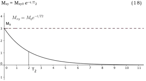
3.2.3 Transverse relaxation time T2……….. 59
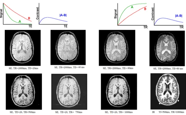
3.2.4 Inversion Recovery and Spin-Echo pulse sequences………… 60
3.3 Magnetic Resonance Imaging (MRI)……… 63
3.4 Chemical shift……… 67
3.5 MRI scanners………. 68
3.6 MRI applied to Cultural Heritage……… 69
4. Raman Spectroscopy and Surface Enhanced Raman Scattering (SERS) 73 4.1 Raman Spectroscopy………. 75
4.1.2 Surface Enhanced Raman Scattering (SERS)………. 76
4.2 Surface plasmons in metallic nanoparticles……….. 81
4.3 Raman imaging: principle and statistical data analysis……… 94
4.4 Raman imaging and SERS applications………. 100
5. Novel diagnostic approaches for wood characterization 104 5.1 Multislice Computed Tomography (MSCT) results on contemporary samples and wooden painted tablets……….. 105
5.2 Nuclear Magnetic Resonance (MRI and µMRI)………. 124
5.2.1 MRI clinical scanner results on contemporary samples……124
5.2.2 MRI clinical scanner results on archaeological waterlogged samples………. 142
5.2.4 µMRI results on archaeological waterlogged samples……… 151
5.3 FTIR, Raman/SERS and SEM-EDX……… 155
5.3.1 FTIR and Raman/SERS results on contemporary samples.. 155
5.3.2 SEM-EDX, FTIR and Raman results on archaeological waterlogged samples………163
5.4 UV-vis optical absorption, FTIR and Raman/SERS results on painted wooden tablets………..168
6. MSCT characterization of an Egyptian Coffin 175 6.1 Egyptian coffin………. 175
6.2 MSCT and post-processing techniques……… 176
6.3 MPR and VRT results………. 179
6.3.1 Multi-planar Reconstruction (MPR)……….. 179
6.3.2 Volume Rendering Technique (VRT)………. 185
6.4 Discussion and conclusions……… 192
7. MSCT characterization of a seventeen-century Dutch wooden painting 196 7.1 Dutch wooden painting………. 196
7.2 MSCT results and discussion………. 198
208 210 228 Conclusions References Appendix Acknowledgments 233
Introduction
To understand what has happened to a historic object, it is
important to know the structure of the original wood. All this must
be done through non-destructive techniques without compromising
the integrity of the observed object.
In recent years, it emerged the importance of defining the
relationship between the morphological characteristics and the
micro- and ultrastructure of wood tissues, as expressed by the
thickness of tracheid walls, lignin content and crystallinity of
cellulose as well as by its hydrophobic capacity. On the overall, it is
essential a profound knowledge of the compositional-structural and
morphological properties of wood and, particularly, a knowledge of
their interdependencies. With this information, it will be possible to
understand the degradation that has occurred over time and, in
turn, to define a potential method of conservation and preservation
of the artworks.
Technological progress has allowed the development of many
non-destructive diagnostic methods, such as X-rays Computed
Tomography (CT), ultrasounds (Zisi 2017), Nuclear Magnetic
Resonance (NMR) (Proietti 2014) technique together new working
configurations of the conventional FTIR and Raman spectroscopies
(Macchioni 2012, Gierlinger 2007). CT and NMR techniques are very
widespread in the field of medicine, allowing to observe internal
parts of the human body without any harm to the patient. Although
they are non-destructive diagnostic tool traditionally applied in
clinical medicine, its application to materials science is a field in
continuous evolution.
The research activities carried out during the PhD course in
Physics whose results are reported in this thesis regard the
development of a protocol suitable for the study of ancient wood by
clinical CT and NMR. First, contemporary wood samples were
analysed to define and optimize CT and NMR procedures. Then, the
same techniques were used to characterize archaeological
waterlogged wood samples and ancient wooden objects. Then, CT
and NMR results were combined to those obtained by micro-imaging
NMR, micro-Raman and FTIR spectroscopies. The synergic use of
these techniques, probing the system energies on different scales, is
proposed as an innovative approach, which have allowed to carry
out wood and wooden works analyses in a systematic and complete
manner. Furthermore, for the first time, the interesting potentiality
of the comparative analysis of all the collected data have allowed to
characterize materials on an Egyptian Coffin and its implementation
methods, making possible to recognize reuse wood planks. On
waterlogged wood samples coming from Naples and Denmark
information about water imbibition were collected. Identification of
the species were performed for the first time with NMR-microimaging
analysis.
CT analyses were carried out at Neuroradiology Unit-Department of
Policlinico University Hospital of Messina, Italy.
NMR measurements were carried out in the NMR Laboratory of
Institute of Complex System of the National Italian Council of
Research (CNR-ISC) at Sapienza University of Rome and at IRCCS
Santa Lucia of Rome, Italy.
Ultimately, FTIR and Raman analyses were carried out in MNS
laboratories in the MIFT Department of the University of Messina.
Chapter 1
Cultural Heritage wooden objects
investigations: state of the art
The evaluation of the conservation state of archaeological wood and, more generally, of degraded historical and architectural wood, is a very important question, because since ancient times wood has been widespread used for many purposes. The conservation of wooden artifacts is again today an actual challenge: big archaeological finds, such as ships, require not only to determine their chemical composition but also their structural-morphological properties in view to define their degradation state to choose a conscious and durable consolidation method.
Wood undergoes several degradation processes depending mainly on the conservation environment. Recently, waterlogged wood is the most studied.
A lot of conservative treatments have been tested mainly with a chemical approach using alum, colophony, poly (ethylene glycol) (PEG), and in situ polymerization. The aim to replace water in the cavities with a penetrating material having a rather low vapor pressure. However, during ageing, most of the methods show problems such as change of pH, lack of penetration, presence of metal ions and so on.
Thus, it is necessary to found more appropriate methods for the removal of old applied products, also investigating the effect of the application of new materials.
Nowadays, the instrumental techniques used for these purposes are: • transmission and scanning electron microscopy (TEM and SEM-EDX) for a characterization of wood at microscopic level to obtain information on morphology, wood species, degradation state and effects of consolidation treatments.
•analytical pyrolysis coupled with gas chromatography/mass spectrometry (Py-GC/MS), which has the advantages to require minimal sample pre-treatment and very low amount of sample, to distinguish different kinds of wood, analyse separately wooden components (lignin and cellulose), evaluate the degradation state at semi-quantitative level.
• infrared spectroscopy (FT-IR) to investigate the changes in the linkages between wood polymers and nuclear magnetic resonance (NMR) to obtain information on the degradation state and the differences between wood species.
• X-ray diffraction (XRD) to understand the structure of wood at cellular level. Recently, X-ray microtomography (µ-CT) was proposed to highlight the presence of heteroatoms and map wood sections with a micrometric resolution.
However, todays, a well-organized protocol is not disponible since an optimization of CT parameters must be made and not all its potential has been exploited (see the possibility of obtaining information on the density of wood and the additional materials it contains). Therefore, the research on archaeological wood involves several aspects: optimization of analytical methods, study of reference (i. e. modern wood) and archaeological woods, investigation of new materials for conservation and consolidation, representing an interesting challenge.
These topics are presented and discussed in this thesis, in order to answer some still debated questions on archaeological wood and especially on wet wood, proposing the combination of results from recently used diagnostic techniques such as CT and NMR with those obtained with conventional techniques such as FTIR and Raman, whose setups have been upgraded to create compositional-structural maps and statistical analysis on a large portion of the same sample. Finally, since the analytical techniques employed for the research activities discussed in this thesis allow to collect large data set relating to a high number of samples and analytes, multivariate statistical techniques will be applied to interpret the results (i. e. principal component analysis). This will allow to compare samples in a quantitative way, to integrate the information from the same sample studied by more than one analytical technique.
1.1 Wood structure
In cultural heritage, the keen interest in determining the woody species of an artefact also implies a more in-depth knowledge of all those cultural aspects. By wood identification, it is possible to obtain information about raw materials offered by territory or about peculiar processing techniques and possible exchanges involving different communities.
To better understand the study of wood-based materials, some general information on wood and its properties is provided below.
Wood is an anisotropic material. As it is well known, wood material comes from Gymnosperm, most commonly call coniferous, or from Angiosperm plant also known as deciduous. Conifer wood has a homogeneous structure, and, for these reasons, it is also called softwood wood, while Deciduous wood presents inhomogeneous anatomy and it is called hardwood wood (Fig. 1).
Moreover, from the macroscopic anatomical details (within a growth ring or annual ring), it is possible to distinguish between springwood (early) and latewood. In Conifers, springwood is made up of cells with a large lumen and a thin wall, while latewood has cells with a much smaller lumen and
thicker wall. This difference in the thickness of the cell wall leads to the difference in colour and hardness. In Conifers, wood spring is lighter and more tender, latewood darker and more compact. In the Deciduous trees, moreover, it is possible to distinguish three main groups: porous-zoned wood species, semi-porous-zoned wood, and porous-diffused wood.
Figure 1 - Morphological details of different structures between hardwood and softwood. (Andersson et al. 2006, Optic Express Open Access).
Wood is a well-known structure. Starting from the bottom, a tree consists of 1) roots that have the function of both anchoring the tree on the ground, and the physiological function of absorption of water and substances in the soil; 2) stem covered with a protective layer called bark; 3) hair which includes the end of the stem, the branches, and the leaves.
The stem is the part that is most used and is divided into several zones. Starting from the end inwards we meet: 1) bark is formed by a more outer part, consisting of dead cells, called rhytidome with a function of protecting the stem from the attack of insects and by drying, and by a more internal
layer called phloem which is meant to transport to all parts of the trunk the sap processed by the leaves during the process of photosynthesis; 2) cambium is a very thin state of cells that varies during the vegetative season of the tree, ; 3) wood or xylem outs-of-body, the sapwood, which in addition to playing a supporting role in the plant, carries the raw sap from the roots to the leaves, while the innermost part is made up of heartwood, with the only function of supporting the plant; 4) Pith, made up of parenchymatic fabric, represents the primary nucleus around which are later developed the growth of the plant.
The tree consists mostly of lignified cells, rigid cell wall quarries (Brunetti 2009), the latter determines the characteristics and behaviour of the wood. Constituents cell walls are similar for all species: cellulose from 40% to 50%, lignin 18-25% in hardwoods, 25-30% for conifers, and hemicellulose from 13% to 27%. More details are reported in the Appendix.
Particularly, the cell wall (Fig. 2) is distinguished in several layers: 1. Primary wall, it is the first to form immediately after the birth of the cell. 2. Secondary wall, the thickest, formed once the cell lengthening is finished.
In addition to the cell walls, which make up the natural woody material, other substances such as water, extractives, and some cellular species are included. Extractives are the product of plant metabolism and can be contained within or deposited on or inside the cell wall, affecting some of the wood characteristics (colour, durability, and impregnability, etc.). The compounds that most found in extractives are terpenes, phenols, tannins, and nitrogen compounds. The cellular species included are usually granules of silica, oxalate or phosphate minerals mainly found in tropical timbers.
We now provide further details on softwood and hardwood structure, being two major classifications of primary importance in the study of archaeological woods
Figure 2 - Wood cell structure (High et al. 2020, Heritage Science Open Access)
1.2 Softwood and Hardwood
Coniferous wood is called softwood because it is made up of homogeneous elements, such as tracheid. These are long spindle-shaped cells which perform the function of lymph conduction and support. Some species, such as Douglas, have characteristic helical thickenings within the walls of tracheid. Parenchymatic cells are arranged in radial section and form uniseriate rays, that is formed by a single row of cells.
The main feature of coniferous wood is the presence of resin channels except for silver fir, cypress, yew, and cedars. In these species, however, resin channels are not excluded as consequences of injuries or trauma. Softwood has well-marked growth rings due to the thicker walls of the tracheid’s formed at the end of the vegetal period (late-wood) compared to those that have formed previously (early-wood). The accretion rings are
also called annual rings. This term, however, can be misled, as it may be suitable for plants that grow in temperate climates where climatic conditions are conducive to the development of the plant. Sometimes, however, due to accidental causes such as a mainly dry vegetative month or an insect attack, there may be an interruption in the development of the plant. Generally, it involves the formation of two rings in the same year; the innermost is called a false ring. The false ring stands out because it has the most faded exterior (Jacquiot 1955, Giordano 1981).
The wood of the angiosperms is much more complicated than that of conifers. There is a greater variety of cells due to the increased specialisation of them. There are cells for the conduction of liquids (vessels), cells that have mechanical resistance functions (fibers) and parenchymatic and secretric cells like softwoods.
The vessels are of different sizes and can be distributed in various ways within each accretion ring. In some species, if the vessels formed at the beginning or end of vegetative recovery, dimensional differences are visible. These differences give rise to porous circles visible to the naked eye. Fibres, on the other hand, are the main protagonists that determine the physical and mechanical characteristics of wood. Parenchymatic cells are more numerous in hardwoods than conifers and are arranged both radially and axially. They can form both uniseriate and multi-striates rays (formed by one or many cell rows) (Jacquiot 1973, Giordano 1981).
1.3 Wood identification
The identification of woody species in the field of cultural heritage and beyond, is a subject not of simple interpretation. Some timbers have macroscopic characteristics so obvious that recognition is certain even with the naked eye. Instead, others need microscopic observation that does not always lead to safe identification of the species.
This difficulty is further exacerbated by the fact that, even within the same species, wood can have different characteristics. There are variations in
the structure of wood due to external and internal factors such as the climate, the soil, and the age of the tree. For example, tree-ring analysis and the relationship between early-wood and late-wood can only be indicative features because they depend on the place where the plant grew more than the intrinsic characteristics of the woody species.
Besides, over time, we witness the phenomenon of the hardening of the innermost part of the trunk. The vessels vary in size, and this also applies to the length of tracheid and fibers as well as the length of the rays can also vary. Therefore, to facilitate the identification of the woody species, samples from the stem of adult plants, taken not near the center of the trunk, nor close to the insertion of branches, should be analyses. Healing fabrics, rubber or resin pockets should also be considered. In short, it should have a sample of wood that is structurally normal.
These conditions are sporadic in the field of cultural heritage, as often the samples to be analyses cannot be chosen with such accuracy. Only rarely is a given character so typical that it can immediately identify the species. Therefore, very often, it is possible to identify only the genus. Hence, to recognize some wood, the various characteristics are analyzed and proceed by exclusion.
First, wood elements are variously oriented and present different properties; as a result, it is essential to define reference direction concerning its anatomical structure. Ideally, assimilating the stem of the tree to a cylinder whose axis coincides with the pith and the accretion constitutes a succession of coaxial cylinders, three different anatomical sections can be defined (Fig. 3) (Nardi Berti 2006):
1) the transverse section or cross-section, perpendicular to the axis of the stem where the rings of accretion are visible.
2) the radial section, parallel to the medullary axis and passing by the center of the stem, where rings will appear as parallel lines.
3) the tangential section obtained from planes parallel to the medullary axis but not passing by the center of the stem.
Figure 3 - Anatomical section of wood (Bajpai 2018, Elsevier with permissions).
Regarding the identification of softwood and hardwoods, the main characteristics that need to be observed are shown below.
For softwood identification, it is necessary to remember that everyone has a very similar structure with few differences, so microscope observation is preferable to macroscopic one (Giordano 1981).
For the macroscopic observation, initially, if the sample consists of a stem wheel, it should be observed whether the heartwood differs from the sapwood or not. The amplitude of the accretion rings and the width of the late-wood compared to the early-wood are then analysed, paying attention to whether the transition between the two is abrupt or gradual.
Finally, the presence or not of resin channels should be evaluated.
For the microscopic identification, the anisotropy of the material must be considered and then the information should be obtained following the anatomical section according to which the sample has been cut (Phillips 1941). For example, if a cross-section is observed, tracheid appear as sub polygonal cells with thicker or less thick cell walls and lumen. Further, resin channels appear as large circular holes and parenchymatic cells as cell cords. Conversely, if you look at a radial section, the tracheid will appear as rectangular tubes with large areolate punctuations inside them.
It is possible to find very large punctuations occupying a crossroads alone (rectangles formed by the walls of a radial parenchymatic cell and an axial tracheid), or other tiny ones located in various ways in the crossing fields (see Fig. 4). Therefore, the punctuations can be: 1) cupressoid; 2) piceid; 3) pinakoid; 4) fenes striform; 5) toxoided (Messeri 1967). Finally, another essential diagnostic character is the presence or not of helical thickenings within the walls of the tracheid.
Figure 4 – Radial section of softwood Picea abies (InsideWood 2004, Open Access database, http://insidewood.lib.ncsu.edu/search)
In the tangential section, however, it is possible to observe the height of the rays and the number of rows of cells that compose them. Then it is possible to infer whether they are striates or biseriates, whether their shape is exhausted and the presence or not of horizontal resin channels (see Fig. 5). Finally, it is essential to check the thickness of the walls of the epithelial cells and their number. Also, in this section, you can observe the presence of helical thickenings.
Figure 5 - Tangential section of softwood Picea abies (InsideWood 2004,
Open Access database, http://insidewood.lib.ncsu.edu/search)
In the case of hardwoods, the macroscopic examination is fundamental (Hart 1971, Giordano 1981). In this case, the first step is to observe the presence or not of the porous ring. First, it is observed if the rays are visible to the naked eye and if the heartwood and the sapwood are differentiated. The changes in colour and in weaving are other essential features to classify the wood.
Furthermore, looking at the sample under a microscope, the shape and size of the vessels can be observed in cross-section. It is crucial to observe if there is a big difference between spring and autumn pots, their number, and their distribution within the accretion rings. By looking at the rays, it is possible to define whether they are striated, multi-striates or aggregated. Finally, it is essential to detect the presence of axial parenchyma for diagnostic purpose.
The analysis in the radial section, it is possible to observe the type of vassal perforation of the vessels and the type and distribution of the intervascular and radius-vase punctuations as well as helical thickenings. Some of these evidences could be confirmed by the analysis in the tangential section (i.e. the type of rays, vassal drilling and helical thickening).
All these features are difficult to remember; so, experts use dichotomic keys of identification to help identify woody species (Wheeler and Baas 1998). IAWA keys are the most used by experts (IAWA 1989). A scheme of softwood identification using dichotomic keys is reported in fig. 6. There are dichotomic keys with indications for macroscopic and microscopic recognition. Generally, it is essential first to identify the type of wood. Once it is established that the wood is softwood or hardwood, the anatomical characteristics must be considered, to narrow the field until the identification of the species.
Figure 6 - Scheme of wood identification key. (Tri Bahtiar et al. 2016, Elsevier Open Access)
1.4 Water and wood
One of the peculiarities that distinguish the wood from all other materials is its hygroscopicity. It is so strong its affinity with water that we can speak of a “wood-water system”. In the trees, the woody fabric is very rich in water, in the form of saline solutions contained in the cell lumen. Once the wood is at room temperature, a progressive loss of water from cellular cavities occurs; replaced by air at ambient pressure. Subsequently, even if the cellular lights are entirely emptied, in the wood it will continue moisture is present which can only be eliminated by drying the wood in oven at 103° C until it reaches the anhydrous state (Bonamini 1996). Generally, researchers distinguish:
- Free or imbibition water is the liquid water that fills the cellular lumens and can flow freely from cell to cell in fresh wood conditions. This type of water it only marginally influences the characteristics of the wood.
- Water connected to cell walls, known as saturation water: is the one that by the formation of hydrogen bonds is combined with free oxydrilic radicals, available walls and mainly related to the molecular structure of microfibrils of cellulose; this is the type of water that greatly influences the properties of wood (Bonamini 1996).
- The water of the constitution (or chemistry): water molecules that have become part of the chemical composition of the main molecules that make up the wood, so its release would lead to the destruction of the wall itself (Nardi Berti 2006).
- Water vapor in the air partially fills the cellular cavities and is in balance with saturation water and imbibing water.
As humidity has a significant impact on the size and characteristics of mechanical and stickiness by insects and fungi, it is crucial to establish the water content inside the wood.
Some physical parameters were analyzed. Among them, the absolute and relative humidity of wood. The absolute humidity is the amount of water vapour that can be contained within a given volume of air. More precisely,
the absolute humidity is the ratio of the mass of water vapour to the mass of dry air:
𝐻𝐻 =𝑀𝑀𝑣𝑣𝑣𝑣𝑣𝑣
𝑉𝑉𝑣𝑣𝑎𝑎𝑎𝑎 (1) where Mvap is the mass of steam contained inside the wood vessel and V
air is the volume of air.
Imagine having a cylindrical vessel sealed tightly by a piston and partially filled with distilled water and the rest with air (at least initially) dehydrated. At a certain temperature and pressure condition, some water molecules will leave the surface of the liquid turning into steam that will be mixed with the air. The steam addition in the container determines an increase in pressure inside the container. If you consider the pattern of evaporation as a function of time, you will be able to obtain the ratio of steam mass contained in the cylindrical vessel and the volume that occupies the air. This ratio is called absolute humidity of the air.
Really, the evaporation process continues until the maximum value of steam has been reached, within a given unit of volume, defined as humidity air saturation. If you enter additional water vapour into an already saturated mass of air, the excess amounts will tend to condense (visible in the form of droplets suspended in the air or directly on the walls of the container that contains them). This effect can also be achieved, decreasing the temperature of a saturated air mass (keeping the pressure constant). The point dew is the temperature at which condensation of the vapour contained in a certain mass begins. At the level of the hygroscopic properties of wood, it is essential to know the relative humidity percentage ratio of actual absolute humidity (Heff) humidity of saturation (Hsat)
reachable from the air, at constant temperature and pressure.
𝐻𝐻𝑟𝑟𝑟𝑟𝑟𝑟 = 𝐻𝐻𝐻𝐻𝑒𝑒𝑒𝑒𝑒𝑒𝑠𝑠𝑣𝑣𝑠𝑠 (2)
National and international standards describe wood moisture as the ratio between the weight of the water contained in the wood (p − p0) and one of the woods in the anhydrous state (p0), expressed in percentage:
𝑀𝑀 =𝑝𝑝−𝑝𝑝0
𝑝𝑝𝑜𝑜 %100 (3) The range of possible humidity values that wood can assume is called the hygroscopic range. It is between 0%, which is obtained when the wood is kept in a long-time dry air, and about 30% reached by placing the wood in an environment saturated with vapor.
Outside the hygroscopic range, wood can still absorb water but only for imbibition, i.e. by direct contact with liquid water which fills the cellular cavities in the form of free water. The imbibition water does not cause significant variations in physical and mechanical characteristics, excluding an increase in density. Generally, wood with 12% of moisture content at 20° C and 65% of relative humidity, it is considered in hygrometric equilibrium.
The moisture value of the wood when free water has been eliminated, and bound water is still present, is called the saturation point. This variable is significant because it indicates when significant variations in physical-mechanical properties of wood (volumetric shrinkage, stiffness, etc.) are occurring. It depends on several factors such as the wood species, the presence of extractives, the volumetric mass, the percentage of earlywood and latewood, temperature, and presence of reaction wood. Conventionally, the wood humidity corresponding to the saturation point varies from 28 ÷ 40% dry weight. In the case of wood in hygroscopic equilibrium, with the moisture content of 12%, absence of free water and partial presence of bond water will occur.
The variation of the water content in the wood involves dimensional variations, which are expressed with swelling, in the case of moisture absorption and with shrinkage, caused by loss of moisture. This phenomenon occurs only in a well-determined range, which goes from anhydrous state to the point of total saturation of the cell walls. Only when the binding water is involved, physical modifications that lead to significant dimensional changes will happen. Particularly, the anisotropy of the withdrawals is a characteristic parameter. For example, going from fresh to dry wood, in the axial section a dimensional change of less than 1% will occur; in the radial direction changes from 3% to 7,5% will happen and from 5,5% to 15% in the tangential section. All these modifications are related to the "biological nature" of wood.
1.5 Analytical methods for assessing
archeological wood
The non-destructive assessment of the physical properties of wood originates in the need to solve practical problems without destroying the integrity of the object under inspection. The first non-destructive assessment of wood was a visual inspection, primarily used for the selection of timber used as supporting members for specific applications. Even today, this method is widely used for the classification of wood products for timber, poles, plywood, etc. and to assess the state of conservation.
At the beginning of the 20th century, with the development of the theory of elasticity and instrumentation for measuring the properties of wood, new scientific methodologies of the non-destructive evaluation were developed.
Initially, the focus was on determining the elasticity modulus using static methods (Horig 1935; Kollmann 1951). Subsequently, acoustic vibrations were used to determine the elastic constants of wood (Barducci and Pasqualini 1948; Hearmon 1948; Kollmann and Krech 1960; Jayne 1955; James 1959).
In the 1960s, the development of X-ray techniques for the evaluation of the internal structure of wood led to the development of densitometry (Polge 1978), and X-ray dispersion also came to light. It was developed in Japan precisely for the study of crystalline wood cellulose (Fukada 1965 and 1956).
In the same years, dynamic tests with vibrational methods for structural timber assessment were also used by Hoyle (1961), Senft et al. (1962) and Pellerin (1965).
In the late 1970s, a congress organized in the United States at Washington State University by Pellerin and colleagues in collaboration with the Forest Products Laboratory encouraged and paved the way for the development of non-destructive methodologies for wood science.
From that moment on, scientific production on the subject grew considerably. (Jayne 1972, Bodig and Jayne 1982, Torgovnikov 1993, Bucur 1995).
Ten years later, the first encyclopedia of wood science was published (Schniewind 1990).
The last 20 years of the 20th century have been characterized by an extraordinary development of techniques for the non-destructive evaluation of wood products. Particular attention should be given to imaging, a methodology par excellence non-destructive.
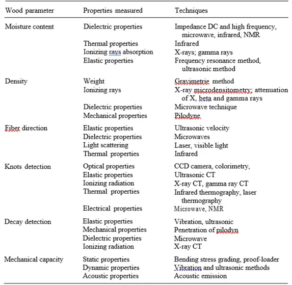
To date, non-destructive techniques are widely used for measuring physical, mechanical, chemical, aesthetic, etc. properties. For example, wood defects, porosity or density variations can be detected by techniques such as microwaves, thermals, X-rays or classic static methods. These methods can help to understand the behavior of matters under different environmental conditions. Other approaches, involving the use of non-destructive survey methodologies, may be the industrial field for the assessment of the quality of materials and the market for wood-based composites that are now booming (Youngquist and Hamilton 1999). Therefore, the need to characterize wood-based composites has stimulated the development of many non-destructive methodologies. This field also requires the synergy of many scientific disciplines, making the matter multidisciplinary. In this regard, Sobue (1993) proposed the classification of non-destructive methods (Table. 1) for the assessment of the physical properties of wood such as moisture, density, stress assessment, node detection, etc. These same methodologies are largely used for studying ancient wood (Bucur 2003).
Among the wood-based objects, submerged archaeological wood can present difficult challenges due to its vulnerability. Quantifying the conservative state and understanding the mechanisms of degradation is therefore crucial. An appropriate analysis manages to establish a solid baseline against which any further deterioration can be traced. For example, when a site is monitored (Brunning 2000) or when experimental data on decay mechanisms is collected (Lucejko 2018).
Another aspect essential in artworks preservation is the monitoring of the state of conservation.
Table 1 – Classification of non-destructive physical methods for solid wood analysis (Bucur 2003, Springer with permissions).
In this way, it is possible to identify when conditions are not conducive to the continued survival of an object (Lucejko 2020, Braovac 2016).Besides, scientific investigations during or after conservation allow assessing whether a protective or consolidating treatment worked or not (Christensen 1970).
As has been widely explained in Appendix 1, fresh wood consists of three main biopolymers, lignin, cellulose and hemicellulose. Archaeological wood is subjected to such a variety of chemical and biological degradation processes that it results in chemical composition and a very different structure than fresh wood (Fengel 1991). In the anoxic conditions provided underwater, decay processes are significantly slowed down and mainly driven by anaerobic biological agents (Blanchette 2000).
These agents mainly attack the hemicellulose, which, due to enzyme degradation, becomes vulnerable (I 1990). The chemical deterioration of cellulose occurs under extreme conditions such as low pH (High 2016). Lignin, thanks to its highly stable structure, is much more resistant to degradation (see Aappendix 1 for more detail). This explains why submerged archaeological wood is characterized by high lignin content (Martinez 2005). Instead, the structure of the wood is maintained because the cell walls are filled by water, but this aligned skeleton is a very fragile material (Bjӧrdal 2003). The decay of lignin is mainly due to the attack anaerobic fungi that digest lignin through enzymatic oxidation (Pedersen 2013). This results in a higher concentration of guaiacyl-type than the syringil one (Hedges 1990).
Another important aspect is the exchange with the surrounding environment. The chemical composition of the submerged wood can change because of this. Also, the highly porous structure of wood can incorporate inorganic minerals, such as iron sulphites, phosphates and calcium, into cell walls (Panter 1997). Identification of these inorganic components can be predicting the success of conservation treatments and possible long-term effects. However, the submerged wood study is quite complicated because of its heterogeneity. Generally, the degradation expands first on the surface and then proceeds inwards. For this reason, the heartwood is always better preserved than the sapwood, which is more external (Christensen 1970).
The methods for analyzing these processes traditionally consist of easily accessible and inexpensive techniques (Blanchette 2000, Jagels 1981). However, in recent decades, thanks to the interdisciplinary nature of diagnostics for cultural heritage, more complex methods have been adopted. An example is advanced microscopic methods that reveal structural alterations or spectroscopic techniques that give information at the molecular level (Daniel 2016). The principal diagnostic methodologies used to study submerged woods will be discussed below (Tab. 2, Tab. 3 and Tab. 4).
One of the techniques widely used to acquire information about the loss of woody substance, a fundamental parameter for determining the structural integrity of an artefact, is the calculation of mass or volume. It
is a very accessible and cost-effective methodology (Jensen 2006). The density and maximum water content (MWC) are also the commonly applied parameters (Macchioni 2012). Another method to assess the loss of woody substance, is the calculation of porosity by filling pores with an inert gas (helium) (Babinski 2014, Donato 2012).
Unfortunately, however, the main problem with these measurements is the difficulty in developing a standard. Once the sample has been removed from the oven, the high porosity of the wood results in very rapid reabsorption of air moisture (Panter 1997), also, to obtain reliable information, it would be necessary to have samples with a minimum size of 2x2 cm. It is not possible to detect small variations in the composition of the wood in a short monitoring period. Hence, one downside of the analysis of wood substance loss is that the methods are often destructive as they require irreversible drying of the sample. Therefore, the use of non-invasive instrumental methods is preferable. One of the most used methods is the X-ray imaging. Thanks to this method, it is possible, for example, to locate limestone deposits caused by marine organisms (Knight 2019). You can also identify elements inside, such as iron nails or joints (Karsten 2010). One drawback of X-ray analysis is that the object is represented as a 2D object.
However, this drawback is outdated by computed micro-CT microtomography (micro-CT) which is a version that can produce 3D images, thus providing a better spatial assessment than normal X-ray (Sodini 2012). Micro-CT can examine objects ranging from millimeter size. The micro-CT can be significantly improved using synchrotron sources (Mizuno 2010). Synchrotron radiation provides better contrast and organic conservation agents (i.e. polyethene glycol (PEG) could be highlighted (Bugani 2009)).
Another widely used method is ultrasound tests and have the advantage that the effect of water can be quickly recorded. However, the interpretation of the data can be complicated as the reflected signal is influenced not only by water content but also by factors such as the orientation of timber and natural variables within wood (Arnott 2005). Another experimental approach that involves the use of rays is the X-ray diffraction (XRD). It has been used to examine cellulose loss in
archaeological wood (Giachi 2003, Li 2014), but the exact location of the deterioration cannot be determined.
Concerning the study of the presence of inorganic salts or structural collapse of cell walls, microscopic methods (optical, SEM, UV, TEM) are the most suitable (Blanchette 2000). Unfortunately, however, the region of the sample analyzed under the microscope may not be representative of the entire object. Besides, preparing samples on degraded samples for a less experienced analyst can be difficult. A more established method for determining chemical composition is to determine the "insoluble lignin" or "Klason lignin" (Babinski 2014). However, the method requires chemical extraction of wood extractants, a high content of sample (> 1 g (Nilson 2012), long analysis times (several days) and the need to manage potentially harmful chemicals. Further, the certainty of the results may depend on the degree of decay that exists in the sample (Pizzo 2010). Moreover, the potentiality of the thermogravimetric (TG) technique applied to the submerged wood has been demonstrated by Romagnoli (2018). However, despite its advantages, TG analysis tends to be applied to more for the evaluation of conservation methods linked to wood (Donate 2010). Other methods widely used to establish relative amounts of cellulose and lignin are the spectroscopic techniques (FTIR and Raman), gas chromatography and nuclear magnetic resonance imaging (NMR) (see Tab. 3 and Tab. 4).
Concerning FTIR analysis, although it is a simple method in a practical sense, the complexity of the material leads to considerable difficulty in interpreting the data, as the water signal often tends to obscure signals from polymeric materials. In addition, only a small part of the sample is measured, as the penetration radius of an FTIR spectrometer is about 0.5-3 µm. The sample is usually analyzed dry, and for submerged wood, FTIR analysis is not suitable.
For this reason, recently Raman analysis in addition to the fact that no sample preparation is required, can be used in a non-destructive way. This method has been less widely applied to archaeological wood analysis than the FTIR since the Raman peaks on dry wood samples are often weak and difficult to compare.
Pyrolysis, on the other hand, is paired with gas chromatography (py-GC) and is a technique in which a sample is exposed to high temperature (> 500 degrees centigrade) in the absence of oxygen. The py-GC provides a more sensitive analysis than FTIR and subtler changes to their poly mechanical structure can be detected. The main factors that limit the routine use of this technique lie in the limited availability of the required instrumentation and the increased expenditure. Also, the analysis times are longer (between 40 mins and 2 h per sample) (Lucejko 2015).
Figure 7 - Schematic summarising some of the key factors that may need to be considered in determining the level of preservation assessment that is necessary (High et al. 2020, Heritage Science Open Access)
Finally, the NMR spectroscopy (1H, 13C, 31P) provides information on the structural and spatial arrangement of organic molecules. This makes it ideal for the analysis of complex polymers such as those found in wood (Bardet 2009). In literature, it has been shown how 13C NMR proved to be a valuable technique for examining cellulose and lignin in solid-state archaeological samples (Zoia 2017, Bardet 2002). The limitations of NMR techniques mainly relate to the lack of availability of appropriate tools, their expense both initially and in terms of maintenance, and the high level of expertise required to perform them.
In conclusion, no single technique can be considered the best option, so it is preferable to take a multi-analytical approach (Fig. 7). In addition, emerging technologies and techniques are continually evolving, always enabling new challenges. It is precisely a multi-analytical approach that has been adopted for the study of the materials covered by this thesis. The correlation of CT, NMR, FTIR and Raman data made it possible to study the chemical-physical characteristics of archaeological woods representative of significant historical periods and coming from different geographic regions (Italy and Denmark). Furthermore, the crossing of these data gave the possibility to validate the multi-analytical approach adopted also on submerged woods. The protocols developed could be adopted to extend the study to other historical finds than those analyzed during the PhD course.
Chapter 2
X-ray Computed Tomography
Today, the use of X-rays in the arts sector is quite widespread. The ability to see through the paint film of canvases and panels, revealing the underlying paint, the author repentance, restoration work and hidden signatures, structural abnormalities, deficiencies etc…, justify the great fortune of radiographic techniques in the investigation on ancient and artistic objects.
Conventional radiographic image, even in its completeness, presents difficulties of reading: the refund on a two dimensional surface of the painting complex stratigraphy does not make more accessible the spatial localisation of the individual elements, sometimes making the decryption of the data rather complicated. Thus, the conventional radiographic technique is not considered the best type of cognitive scientific act to investigate the structural situation and a work of art material. On the contrary, X-ray Computed Tomography (CT) is a more valuable methodology for cultural heritage investigations. In this thesis, conventional clinical CT scanners were applied to wooden artefacts investigations. The choice was based on the principle that wood material has similar attenuation to human tissue. The reasons will be explained in detail below, together with a presentation of its operating principle
2.1 Production of X-rays
The equipment for the production of X-rays, the so-called X-ray tube, is shown in Fig.1. An X-ray tube consists of a glass ampoule containing two electrodes acting as an anode and cathode, respectively.
Figure 1 - X-ray tube schema (Courtesy of Prof. Francesca Granata).
The bulb, where the vacuum is created, is surrounded by a metal casing lined with lead. The emission of X-rays takes place through a small not-shielded area, known as 'window'. A current is passed through the tungsten filament and heats it. As it is heated up, the increased energy enables electrons to be released from the filament, usually tungsten, through thermionic emission. The electrons are attracted towards the positively charged anode and hit the tungsten target with maximum energy determined by the tube potential (voltage) (Erriu 2005).
As I will describe better soon when the electrons bombard the target they interact via Bremsstrahlung and characteristic interactions which result in the conversion of energy into heat (99%) and ray photons (1%). The x-ray photons are released in a beam with a range of energies (x-x-ray spectrum) out of the window of the tube and form the basis for x-ray image formation.
The loss of energy is proportional to Z; this is the reason why heavy materials are used for the anode so that higher production of X rays can be obtained. The radiation emitted in this process is known as "continuous Bremsstrahlung radiation" or "radiation of Bremsstrahlung", characterised by a continuous spectrum (energy distribution of the X photons).
Figure 2 - Bremsstrahlung radiation (Courtesy of Prof. Francesca Granata).
A second X-ray production process takes place when the electron projectile has energy sufficient to cause the ejection of an electron belonging to an internal orbital of the atom. The gap which is thus created will tend to be occupied by an electron from an outer orbital. This process determines the emission of a photon of energy equal to the difference between the binding energies of the two levels. Since the binding energy for the electrons is different from element to element, the x-ray spectrum shows a distribution of energy according to a line spectrum, which is characteristic of the material constituting the target (characteristic X-rays). Hence, the resulting spectrum (Fig. 3) is given by the superposition of a continuous component (bremsstrahlung radiation) and a discrete component (characteristic radiation).
Figure 3 - Typical spectrum of x-ray photon energies released (Courtesy of Prof. Francesca Granata).
As already said, the anode must be comprised of a high atomic number material and a high melting point. In fact, in the process above described, only 1% of the kinetic energy of the electron's "bullet" gives rise to the production of X-rays; the remainder is converted into heat. For these reasons, the tungsten (with Z = 74 and T (melting) = 3370 °C) is the materials mainly used as the anode.
Further, "projectile" electrons often fail to transfer sufficient energy to extract electrons from the target atom, so they switch to a higher energy level; when they return to the initial state, the electrons emit infrared radiation which causes the continuous heating of the anode, resulting in its deterioration and possible merger. To obviate, rotating anodes are today used since, in such way, the electron beam is incident in different points of the anode itself, favouring the dissipation of the thermal energy. Finally, the target plate is inclined at an angle of about 20°, so the electrons act within the focal area, of rectangular shape, while the photons are emitted
from an area approximately square, much smaller, called the "focal spot" or "actual focal spot" (see Fig. 4).
Figure 4 – Schematic representation of actual focal spot and effective focal spot (Courtesy of Prof. Francesca Granata).
2.2 Interaction of X-rays with matter
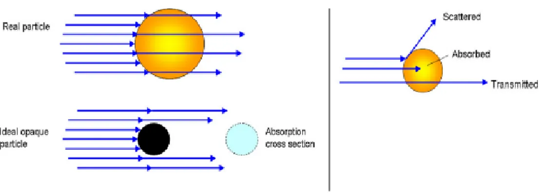
The radiographic techniques, as well as to all imaging systems that rely on the use of X-rays, exploit the fact that the constituents of the X-ray photons have a certain probability of interacting with atoms constituting the material that passes through, resulting in loss of energy and possible release of secondary charged particles.
The so-called cross-section is a measure of the probability that photons interact with matter by a particular process. There are several modes of interaction which depends on the atomic number Z of the target atoms and the energy of the photons. The higher the atomic number, the higher is the interaction probability with an electron in the atom of this element.
The amount of energy absorbed by a body and then the consequent attenuation of the beam changes as a function of the materials linear
absorption coefficient μ, and it is proportional to the thickness x of the material crossed, according to the following law:
I (x) = I0 ex×µ (1)
Where I (x) is the intensity of the beam collected after the interaction, x the thickness of the crossed materials and I0 the intensity of the source. Principally, three kinds of interaction with matter occurs:
a) Transmission: the radiation passes the material without altering energy or direction.
b) Absorption: the radiation is absorbed transferring its energy to the absorbing material.
c) Scattering: the direction of the radiation changes; the energy can also be diminished.
The primary process involved in the interaction of x-rays with matter is the so-called "photoelectric effect", which is one of the principal forms of interaction of x-ray with matter (Fig. 5).
A low energy photon interacts with an electron in the atom and removes it from its shell. The electron that is removed is then called a photoelectron, and the incident photon is wholly absorbed in the process. Hence, the photoelectric effect contributes to the attenuation of the x-ray beam as it passes through matter.
Briefly, a low energy photon interacts with an electron in the atom and removes it from its shell (e.g. K-or L-shell), which is subsequently ejected as a photoelectron, and the atom is ionised (Martin 2006). The vacancy in the shell is filled up with an electron from an outer shell—displacement to the less energetic shell results in the emission of element-characteristic X-ray radiation with lower energy.
On the other hand, the scattering phenomenon of X-ray photons is known as Compton scattering (Compton 1923). The X-ray photon hits an electron in the shell of an atom and is deviated by this collision. It loses energy to the electron, which is ejected from the shell causing ionisation of the atom. Ultimately, the pair production occurred for X-ray photons with energies higher than 1.02 MeV: the photon collides with the nucleus producing an
electron and a positron, respectively. Pair production is not generally used by medical imaging.
Figure 5 - Illustration of the photoelectric effect. For a photoelectric effect to occur, the incident photon energy must be equal to or greater than the binding energy of the ejected electron. For example, photons whose energies exceed the K-shell binding energies will most likely result in photoelectric interactions with the K-shell electrons. As a result of a photoelectric interaction, atoms are ionised with a vacancy of an inner shell electron. An electron from a more outer shell, with lower binding energy, will fill this vacancy. It will, in turn, create another vacancy, which is filled from an even lower binding energy shell, creating an electron cascade from outer to inner shells. The difference in binding energy is released as either characteristic X-rays or Auger electrons. As the atomic number of the absorber decreases, the probability of characteristic X-ray emission decreases. See Ref. (Fassbinder 2012, Wolters Kluwer with permissions).
All these are the basis of the functioning of the tomography instrumentation. Generated photons irradiate an object. Then, they traverse the material of the object, and it depends on their intensity and the nature of the material. In the end, some of the energy is lost (or attenuated), and less energy emerges from the other side. Traditionally, this energy was used to ionise a photographic plate for the creation of an image. Today, specific software is used to digitally encode density and spatial information about portions of the object, as will be described in the following paragraphs.
2.3 Principles of Computed Tomography
X-ray imaging was the first diagnostic imaging technology, invented immediately after the discovery of x-rays by Roentgen in 1895. As described in the previous paragraph, X-rays are a form of electromagnetic energy that propagates through space and are absorbed or scattered by interactions with atoms. The attenuation of beam energy on passage through physical objects provides a non-invasive means to gather information about the amount and type of material present inside the object.
By acquiring multiple x-ray views of an object and performing mathematical operations on digital data, a full 2D section of the object can be reconstructed. It is the mechanism of the Computed Tomography (CT), based on the theoretical work of Radon (Radon 1917; Brooks and Di Chiro 1975). The practical implementation of the principle is based on the work of Cormack (1963) and Hounsfield (1973; 1980) who designed the first functioning X-ray CT scanner.
Transmission images represent shadow images of the examined object. These projections thus contain information on the object's inner structure. This information consists of the integrated attenuation that the beam experiences on its way through the object, yielding information for every point in a two-dimensional plane. A projection of the object made from a right angle from the first viewing angle yields again two-dimensional information. With just these two projections, it is possible to make a rough estimate of the position of an object's structural features in three dimensions. It is nevertheless still scarcely possible to make assumptions about the actual three-dimensional shape of these features. Using projections from different angles can, therefore, help to ascertain the exact form. To reconstruct the actual shape of an object, a computational step called "computed tomography" is required.
Thus, computed tomography is a method using projections from different viewing angles to gather three-dimensional information on an object's inner constitution by reconstructing a three-dimensional virtual model of the object. So, the projections are transformed to tomography slices,
images, which are perpendicular to the projection-plane as well as to the rotation axis of the object (or of the source and detector, as is the case in most medical scanners). These tomography slices represent two-dimensional matrices of the attenuation coefficient values within the reconstructed plane. For every line within the detector, a tomogram is reconstructed. The stack of tomograms represents a three-dimensional array of the attenuation coefficient µ (x, y, z) within the reconstructed volume. By stacking the tomograms, a three-dimensional manipulation, visualisation, and evaluation are possible.
2.4 CT instruments
CT is widely used in clinical diagnostics since it allows to discriminate tissue density and to display specific organs body images (Dal Pozzo 2016). Correctly, industrial computed tomography, portable computed tomography, and micro-CT (µCT) are currently used obtaining detailed images with a resolution down to 1 micron (Kaick and Delorme 2005). These types of instruments consist of a fixed X-ray tube and a rotating platform of 360°, where the object or the sample is placed. However, industrial CT and micro-CT are not suitable for objects with large dimensions (30-40 cm) while portable devices regulations, especially in Italy, are quite restrictive due to the ionisation radiation. Furthermore, scanning times are quite long. Then, high-resolution 3D images reconstructions are possible only with micro-CT, giving only information on small samples (75.8 x 140 mm max.).
A good compromise between detailed images, short scanning time and high-resolution 3D reconstruction is given by the Multi-slice Computed Tomography (MSCT). It is nowadays the most used X-ray CT in medical images analysis. Over time, there have been some generations of CT scanners capable of better performances in terms of scanning speed (gradually reduced from several minutes to seconds to fractions of a second) and resolving power of the image.
The first-generation tomography was based on the emission of a linear beam of X-rays, emitted from an X-ray tube in translational and rotational
movement, and detected by a detector (Xenon or solid-state) entirely in movement. The running acquisition time was of few minutes (Fig. 6) (Kalender 2000).
Figure 6 - Schematic representation of a first-generation CT scanner (Courtesy of Prof. Francesca Granata).
Technological improvements were designed to reduce data collection time drastically. In fact, in the second-generation tomography, the X-ray beam has a fan geometry of 20-30º connected with a group of 20-30 detectors: so, the execution time was reduced to tens of seconds (Fig. 7).
Figure 7 - Schematic representation of a CT scanner of the second generation (Courtesy of Prof. Francesca Granata).
In the third generation, the number of generators was increased, and the range of X-ray embraces the whole object to be examined. In this way, it is no longer necessary to provide translation for each direction.
The source-detector system rotates, continuously, on a 360 ° arc. Consequently, the time for an examination decreased up to 5-10 seconds, allowing the examination of bodies in motion (Fig. 8).
Figure 8 - Schematic representation of a CT scanner of the third generation (Courtesy of Prof. Francesca Granata).
The fourth-generation scanners showed fixed sensors, and soon it has been abandoned. Modern scanners derived from the third-generation scanner have a fundamental characteristic: a spiral configuration for the images acquisition. In a unidirectional continuous rotation tomography, the X-ray tube and detectors are mounted on a rotating ring that is fed to "wiping contacts", with no longer the problem of cables twisting themselves (Technology Slip Ring 6- 1987). This method allows the acquisition of images in a continuous way: while the table which leads the patient to moves on a sliding surface, the scanning planes describe a helix around the patient, obtaining a "spiral" scan.
The problem with this technology, working with oil, was the cooling of the X-ray tube, whose temperature reached 900 degrees during scans. The materials with which the tubes were initially constructed had a minimal heat capacity that did not allow to perform very high duration of scans due to significant overheating effects.
The devices of the spiral CT have evolved, from 1998 until today, characterised by the addition of multiple files (banks) of detectors, hence
the name of multilayer spiral CT: to each rotation, instead of a single layer, multiple numbers were acquired. At the beginning there were 4 layers, then 8, 16, 32, 64, 128, 256 etc. Other significant developments have occurred in the calculation systems and software for image reconstruction, in the sliding contacts and, finally, the X-ray tubes have been constructed to dissipate heat and therefore to allow continuous scans.
2.5 Multislice Computed Tomography
(MSCT)
Multislice Computed Tomography (MSCT) is the instrumentation that allows performing scans in a short time. For example, it can acquire information about human organs in 1 second, about the heart in 5 seconds and the whole body in less than 10 seconds (Goldman 2008).
The units composing a tomograph are mostly three:
1. Scanning unit (gantry): high voltage generator, X-ray tube, collimation system, detectors, and the data acquisition system.
2. Software: handles the scanning and reconstruction of the data.
3. Control console: Display systems, storage, and playback of images (see scheme in Fig. 9).
Figure 9 - Mulsitslice Computed Tomography system (Longo et al. 2018, PhD Report, University of Messina)
The working geometry has been optimised to obtain a correct reconstruction when the plane under examination is irradiated. The most simple tools reconstruct the planes of the cross-sections of the patient's body by directing on them collimated beams of X-rays while an X-ray detector is situated on the opposite side of the patient, relative to the source and the collimator. The source, collimators and the detector rotate by scanning along different directions of a specific plane of the patient's body said tomographic plane. The analysis of the collected data allows reconstructing the changes in the current material density to the plan. Further evolution of MSCT technology consists of the Dual-Energy (DE). By using different hardware and software devices, this method can represent CT scans of data obtained from two different energy spectra, usually 80 and 140 kVp, to differentiate the composition of the fabrics or materials.
During a single spiral scan, data acquisition in DE can be obtained using two radiating sources operating simultaneously in a different energy range, as in CT Dual -Source, or using a single radiating element. In the latter case, the different energy spectra are obtained with systems capable of alternating hundreds of times per second, the voltage values of the tube during the rotation of the gantry, namely a single tube with rapid "switching" of the kVp.
Today, however, CT Dual - Energy is one of the most exciting technological innovations in computed tomography (CT), as evidenced by the growing number of jobs in the literature in various fields of clinical application (Primak 2009)
Hence, CT Dual - Source, thanks to the combined and simultaneous two-pipe systems - detector mounted orthogonally within the gantry- offers the possibility to take advantage of low energy without any loss of image quality. Finally, the combination of two different weighing data set is the goal of image fusion. Furthermore, CT Dual - Source technique offers two options for scanning approach. It is possible to separately assess the contribution of the two pipes, in order to take advantage from the increased conspicuity of the contrast medium (ICM)38 at low energy, or it is possible to melt together the two information to obtain images with quality
characteristics and noise fully superimposable to those of standard images to single energy with tube 120 kVp.
The fusion of the images, as well as with linear technique, is obtained applying a sigmoid technique. The latter allows reconstructing the voxels with high attenuation, such as those of iodine, mainly by the low-energy tube in order to exploit the increased conspicuity, and allows to reconstruct, in contrast, the low voxel attenuation (fat, tissues soft), mainly by the high energy tube, in order to reduce noise. So, it is possible to have a high-quality image comparable to those of the tube to 120 kVp; instead, the perception of enhancement is like that one obtainable at low kVp. Finally, thanks to the vast difference in the attenuation of iodine at different scans voltage, some specific software, based on decomposition systems at three materials (fat, iodine and soft tissue), allows to remove the iodine or superimpose it as a colour map on images in grayscale.
2.6 CT image processing and Hounsfield
units
As already mentioned, the image of the object is created by measuring the attenuation of an X-rays beam. It varies depending on the electron density of the tissues crossed the spatial distribution of the electrons in the layer under examination. Since the resulting images are in a digital format, the object examined is divided into a discrete set of volume elements called voxels, which corresponds to pixel (area) for height (slice thickness) and follow the grayscale.
The voxel is three-dimensional while the pixel is two-dimensional. Size of the voxels depends on the type of collimation and the number and size of the detectors (Kalender 2000).
The smaller area is represented by a single pixel, more significant of the spatial resolution. The attenuation is directly proportional to the electron density of the tissues present in the voxel: its value is called "densitometry". A gradation of lighter grey represents a voxel with high density. The measurement of the electron density is made by using the HU
(Hounsfield units), which includes 2001 different shades of grey, from black to white.
The HU scale is a linear transformation of the original linear attenuation coefficient measurement into one in which the radio-density of distilled water, at standard pressure and temperature, is defined as zero Hounsfield units (HU). In contrast, the radiodensity of air at STP (Standard temperature and pression) is defined as -1000 HU. For any material with linear attenuation coefficient μX, the corresponding HU value is therefore given by:
HU= 1000 • µ - µwater/µwater - µair (2) The Hounsfield units is a relative parameter, where water is taken as a reference substance (Fig. 10).
Figure 10 - Attenuation values in HU of specific organs and tissues. The water-mail is 0, the expression of its measurement system. At the two extremes, the bone, +1000HU, and the air, -1000HU (Longo et al. 2018, PhD Report, University of Messina).
The Hounsfield numbers, assigned to each voxel, are subsequently attributed to an image matrix which usually has a size of 512x512x512 pixels. Finally, thanks to mathematical algorithms, powerful software can reconstruct the image. After the acquisition of the data, many post-processing operations are possible (e.g., the planar and 3D reconstructions). Moreover, there are several modes of visualisation of CT images that can be changed to enhance the information of particular interest or suppress others, if considered irrelevant, by changing the range of greys said Window Width. Changing these values, above and below the considered window, they will have respectively the colours black and white.
2.7 X-ray Computed Tomography
applied to Cultural Heritage
In scientific literature, there are many studies which focus on structural investigations by X-ray CT. This technique has proved to be an excellent aid for materials research. Correctly, industrial and medical CT scanners are used in the timber industry to investigate the internal structure and integrity of wood (Lindgren 1991; Voichita 2003; Steppe 2004) and in archaeology and anthropology to study mummies (Hardwood- Nash 1979; Taconis 2005; Piombino-Mascali 2014) and dental, skeletal remains using microCT and synchrotron radiation (Zanolli 2014). X-ray CT technologies have been widely used for investigations of works of art (Rossi 1999; Sirr and Waddle 1999; Seracini 2005; Morigi 2007 and 2010; Casali 2008; Stoel and Borman 2008; Brancaccio 2011; Re 2012; Tuniz 2012; Parisi 2016). Other fields of X-ray CT application are in geology (Pralle, Bahner, and Benkler 2001) and airport safety (Kaufman 2003; Kaick and Delorme 2005). However, the great variety of size and composition that characterises archaeological findings and art objects requires the development of tomographic systems designed explicitly for Cultural Heritage analysis.